EP3726678B1 - Handling of lost time synchronization in a substation network - Google Patents
Handling of lost time synchronization in a substation network Download PDFInfo
- Publication number
- EP3726678B1 EP3726678B1 EP19169478.5A EP19169478A EP3726678B1 EP 3726678 B1 EP3726678 B1 EP 3726678B1 EP 19169478 A EP19169478 A EP 19169478A EP 3726678 B1 EP3726678 B1 EP 3726678B1
- Authority
- EP
- European Patent Office
- Prior art keywords
- time
- data
- ied
- data sources
- substation network
- Prior art date
- Legal status (The legal status is an assumption and is not a legal conclusion. Google has not performed a legal analysis and makes no representation as to the accuracy of the status listed.)
- Active
Links
Images


Classifications
-
- H—ELECTRICITY
- H02—GENERATION; CONVERSION OR DISTRIBUTION OF ELECTRIC POWER
- H02J—ELECTRIC POWER NETWORKS; CIRCUIT ARRANGEMENTS OR SYSTEMS FOR SUPPLYING OR DISTRIBUTING ELECTRIC POWER; SYSTEMS FOR STORING ELECTRIC ENERGY
- H02J3/00—Circuit arrangements for AC mains or AC distribution networks
- H02J3/04—Arrangements for connecting networks of the same frequency but supplied from different sources
- H02J3/08—Synchronisation of networks
-
- H—ELECTRICITY
- H02—GENERATION; CONVERSION OR DISTRIBUTION OF ELECTRIC POWER
- H02H—EMERGENCY PROTECTIVE CIRCUIT ARRANGEMENTS
- H02H1/00—Details of emergency protective circuit arrangements
- H02H1/0061—Details of emergency protective circuit arrangements concerning transmission of signals
-
- G—PHYSICS
- G01—MEASURING; TESTING
- G01R—MEASURING ELECTRIC VARIABLES; MEASURING MAGNETIC VARIABLES
- G01R31/00—Arrangements for testing electric properties; Arrangements for locating electric faults; Arrangements for electrical testing characterised by what is being tested not provided for elsewhere
- G01R31/001—Measuring interference from external sources to, or emission from, the device under test, e.g. EMC, EMI, EMP or ESD testing
- G01R31/002—Measuring interference from external sources to, or emission from, the device under test, e.g. EMC, EMI, EMP or ESD testing where the device under test is an electronic circuit
-
- H—ELECTRICITY
- H02—GENERATION; CONVERSION OR DISTRIBUTION OF ELECTRIC POWER
- H02J—ELECTRIC POWER NETWORKS; CIRCUIT ARRANGEMENTS OR SYSTEMS FOR SUPPLYING OR DISTRIBUTING ELECTRIC POWER; SYSTEMS FOR STORING ELECTRIC ENERGY
- H02J3/00—Circuit arrangements for AC mains or AC distribution networks
- H02J3/004—Generation forecast, e.g. methods or systems for forecasting future energy generation
-
- H—ELECTRICITY
- H02—GENERATION; CONVERSION OR DISTRIBUTION OF ELECTRIC POWER
- H02J—ELECTRIC POWER NETWORKS; CIRCUIT ARRANGEMENTS OR SYSTEMS FOR SUPPLYING OR DISTRIBUTING ELECTRIC POWER; SYSTEMS FOR STORING ELECTRIC ENERGY
- H02J3/00—Circuit arrangements for AC mains or AC distribution networks
- H02J3/17—Demand-responsive operation of AC power transmission or distribution networks
-
- H—ELECTRICITY
- H02—GENERATION; CONVERSION OR DISTRIBUTION OF ELECTRIC POWER
- H02H—EMERGENCY PROTECTIVE CIRCUIT ARRANGEMENTS
- H02H7/00—Emergency protective circuit arrangements specially adapted for specific types of electric machines or apparatus or for sectionalised protection of cable or line systems, and effecting automatic switching in the event of an undesired change from normal working conditions
- H02H7/26—Sectionalised protection of cable or line systems, e.g. for disconnecting a section on which a short-circuit, earth fault, or arc discharge has occured
-
- H—ELECTRICITY
- H02—GENERATION; CONVERSION OR DISTRIBUTION OF ELECTRIC POWER
- H02H—EMERGENCY PROTECTIVE CIRCUIT ARRANGEMENTS
- H02H7/00—Emergency protective circuit arrangements specially adapted for specific types of electric machines or apparatus or for sectionalised protection of cable or line systems, and effecting automatic switching in the event of an undesired change from normal working conditions
- H02H7/26—Sectionalised protection of cable or line systems, e.g. for disconnecting a section on which a short-circuit, earth fault, or arc discharge has occured
- H02H7/261—Sectionalised protection of cable or line systems, e.g. for disconnecting a section on which a short-circuit, earth fault, or arc discharge has occured involving signal transmission between at least two stations
-
- Y—GENERAL TAGGING OF NEW TECHNOLOGICAL DEVELOPMENTS; GENERAL TAGGING OF CROSS-SECTIONAL TECHNOLOGIES SPANNING OVER SEVERAL SECTIONS OF THE IPC; TECHNICAL SUBJECTS COVERED BY FORMER USPC CROSS-REFERENCE ART COLLECTIONS [XRACs] AND DIGESTS
- Y02—TECHNOLOGIES OR APPLICATIONS FOR MITIGATION OR ADAPTATION AGAINST CLIMATE CHANGE
- Y02B—CLIMATE CHANGE MITIGATION TECHNOLOGIES RELATED TO BUILDINGS, e.g. HOUSING, HOUSE APPLIANCES OR RELATED END-USER APPLICATIONS
- Y02B70/00—Technologies for an efficient end-user side electric power management and consumption
- Y02B70/30—Systems integrating technologies related to power network operation and communication or information technologies for improving the carbon footprint of the management of residential or tertiary loads, i.e. smart grids as climate change mitigation technology in the buildings sector, including also the last stages of power distribution and the control, monitoring or operating management systems at local level
- Y02B70/3225—Demand response systems, e.g. load shedding, peak shaving
-
- Y—GENERAL TAGGING OF NEW TECHNOLOGICAL DEVELOPMENTS; GENERAL TAGGING OF CROSS-SECTIONAL TECHNOLOGIES SPANNING OVER SEVERAL SECTIONS OF THE IPC; TECHNICAL SUBJECTS COVERED BY FORMER USPC CROSS-REFERENCE ART COLLECTIONS [XRACs] AND DIGESTS
- Y04—INFORMATION OR COMMUNICATION TECHNOLOGIES HAVING AN IMPACT ON OTHER TECHNOLOGY AREAS
- Y04S—SYSTEMS INTEGRATING TECHNOLOGIES RELATED TO POWER NETWORK OPERATION, COMMUNICATION OR INFORMATION TECHNOLOGIES FOR IMPROVING THE ELECTRICAL POWER GENERATION, TRANSMISSION, DISTRIBUTION, MANAGEMENT OR USAGE, i.e. SMART GRIDS
- Y04S20/00—Management or operation of end-user stationary applications or the last stages of power distribution; Controlling, monitoring or operating thereof
- Y04S20/20—End-user application control systems
- Y04S20/222—Demand response systems, e.g. load shedding, peak shaving
Definitions
- Embodiments presented herein relate to a method, an intelligent electronic device (IED), a computer program, and a computer program product for handling time shifted data streams caused by lost time synchronization in a substation network.
- IED intelligent electronic device
- substations are part of an electrical generation, transmission, and distribution system. Substations act as connection points between different transmission lines of the electrical system and might additionally transform voltage from high to low, or the reverse, or perform any of several other functions. Between the generating station and consumer, electric power may flow through several substations at different voltage levels.
- a substation may include transformers to change voltage levels between high transmission voltages and lower distribution voltages, or at the interconnection of two different transmission voltages.
- substations are often unattended, relying on remote supervision and control.
- data streams from different data sources within a substation may be fed to a protection function configured to, based on the data streams, make a trip decision and thus to determine whether or not to trip a circuit breaker.
- the data streams need to be time correlated.
- a precise and unified time synchronization of the data sources is thus required for the protection function to work properly.
- a time shift in the time source may imply a substantial propagation delay of the time shift throughout the system within the substation. In turn, this might lead to transient time differences between the data sources that can lead to miss-operations of the protection function. If the data streams received by the protection function cannot be guaranteed to be time correlated the protection function should therefore be blocked such that false trips are avoided.
- US 2011/0063766 A1 discloses a line current differential protection system that uses an external time reference and that continues providing protection to a power apparatus upon the loss of the external time reference.
- US 2011/0063766 A1 discloses that an external time reference synchronization mode and a channel based synchronization mode may be selectively applied on a per channel basis such that only those channels in the system that are not guaranteed to stay symmetrical use external time reference synchronization.
- US 2011/0063766 A1 further discloses that when the external time reference is lost, fallback strategies may be used such as disabling or de-sensitizing the line current differential protection function, switching from the external time reference synchronization mode to a channel based synchronization mode with appropriately selected protection settings, and/or marking the channel as unavailable to isolate the system from the consequences of synchronization errors over this channel and instead using a master-slave mode with other available channels to continue providing line protection with the current differential system.
- fallback strategies may be used such as disabling or de-sensitizing the line current differential protection function, switching from the external time reference synchronization mode to a channel based synchronization mode with appropriately selected protection settings, and/or marking the channel as unavailable to isolate the system from the consequences of synchronization errors over this channel and instead using a master-slave mode with other available channels to continue providing line protection with the current differential system.
- An object of embodiments herein is to provide efficient mechanisms for handling time shifted data streams in a substation network that can be used to improve the performance of the protection function.
- a method for handling time shifted data streams in a substation network is performed by an IED.
- the method comprises receiving a respective data stream from at least two time synchronized data sources in the substation network.
- the method comprises blocking, upon detecting a time shift between the data streams resulting from one of the data sources losing its time synchronization and until a configured time amount has expired, a protection function in the substation network from acting on the data streams.
- the configured time amount is dependent on a clock domain hierarchy of the data sources in the substation network.
- an IED for handling time shifted data streams in a substation network.
- the IED comprises processing circuitry.
- the processing circuitry is configured to cause the IED to receive a respective data stream from at least two time synchronized data sources in the substation network.
- the processing circuitry is configured to cause the IED to block, upon detecting a time shift between the data streams resulting from one of the data sources losing its time synchronization and until a configured time amount has expired, a protection function in the substation network from acting on the data streams.
- the configured time amount is dependent on a clock domain hierarchy of the data sources in the substation network.
- a computer program for handling time shifted data streams in a substation network comprising computer program code which, when run on an IED, causes the IED to perform a method according to the first aspect.
- a computer program product comprising a computer program according to the third aspect and a computer readable storage medium on which the computer program is stored.
- the computer readable storage medium could be a non-transitory computer readable storage medium.
- this provides efficient blocking of the protection function when the data sources are without time synchronization.
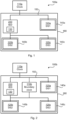
- Fig. 1 is a schematic diagram illustrating a substation network 100a where embodiments presented herein can be applied.
- the substation network 100a comprises data sources 120a, 120b, 120c (denoted DS1, DS2, DS3).
- the data sources 120a, 120b, 120c are configured to generate data streams and provide the data streams to a protection function 130.
- Each data source 120a, 120b, 120c might belong to a respective merging unit 140a, 140b, 140c (denoted MU1, MU2, MU3 in Figs. 4 and 5 ) of a substation 160 in the substation network 100a.
- the protection function 130 is part of, integrated with, or collocated with, an IED 200. There could be different examples of protection functions. In some examples the protection function 130 is a relay protection function or a control function, such as a synchronization check function.
- the data sources 120a, 120b, 120c belong to the MUs 140a, 140b, 140c that provide data streams in the form of analog samples to the protection function 130 via a process bus 150. Each data stream might thus comprise analog samples, for example representing voltage or current measurements of MUs 140a, 140b, 140c in the substation network 100a, 100b.
- the data sources 120a, 120b, 120c are time synchronized by means of a time source 110a, which might act as a grand master clock for the substation network 100a.
- Fig. 2 is a schematic diagram illustrating a substation network 100b where embodiments presented herein can be applied.
- the substation network 100b comprises the same components as the substation network 100a.
- a further time source 110b is provided in the form of a boundary clock.
- the boundary clock is physically separated from the IED 200; the substation network 100a might also comprises a boundary clock that might be integrated with, or collocated with, the IED 200.
- data streams from data sources 120a, 120b, 120c of the MUs 140a, 140b, 140c may be fed to the protection function 130 for making a trip decision.
- all data sources 120a, 120b, 120c might not change time at the same time. This can e.g. be the case when a new time source 110a, 110b is connected to a substation network 100a, 100b that was previously without time synchronization or when different substation networks, each having its own time source, are connected together.
- the new time will ripple from the clock through the substation network 100a, 100b to each data source 120a, 120b, 120c. This means that during a transition, e.g. when a clock regains time synchronization after freely drifting for some time, there will be different times in different parts of the substation network 100a, 100b.
- the time source 110a experiences a failure causing it to lose time synchronization for some time and then regains reliable time synchronization from, for example, a satellite system (not shown).
- the correct time will thus reach MU1 and the IED 200 (including the protection function 130) first.
- the correct time will propagate to MU2 and MU3 through the boundary clock 110b (either provided inside the IED 200 as in Fig. 1 or as a separate entity as in Fig. 2 ).
- MU2 and MU3 will both appear to be time synchronized, but they will in practice have different time compared to MU1 and the IED 200 (including the protection function 130). Therefore, if the protection function 130 is not blocked during this situation, a false trip might be triggered by the protection function 130.
- the blocking of the protection function 130 can be stopped when all devices (IED and MUs) are time synchronized from the same time source.
- the data streams from the different data sources 120a, 120b, 120c might thus be out of time synchronization with respect to each other, which in turn might lead to that e.g. a differential current is registered at the protection function 130 which causes a trip to be triggered, even if there is no fault in any of the MUs 140a, 140b, 140c, or parts thereof.
- this issue can be mitigated by blocking the protection function 130 during these situations.
- One way is to block the protection function 130 when the protection function 130 itself detects a time shift in the data streams. However, this does not help if one or more of the data sources 120a, 120b, 120c shifts time before this time shift in the data streams is detected by the protection function 130.
- Another way is to include information to what master time source each data source 120a, 120b, 120c is connected. However, this only works if all data sources 120a, 120b, 120c (and the protection function 130) support such functionality. This will also block the protections function 130 even if not necessary when the time is the same for all data sources 120a, 120b, 120c but where the data sources 120a, 120b, 120c are using different time sources, e.g. when a main time source is lost for some of the and other time sources take over.
- mechanisms that prevent the miss operations (e.g. by blocking the protection function 130) during the propagation of the time shift. Also, mechanisms are provided to limit the blocking of the protection function 130 as much as possible, but still prevent false trips (i.e., trips without any reason in the substation network 100a, 100b).
- the embodiments disclosed herein in particular relate to mechanisms for handling time shifted data streams in a substation network 100a, 100b.
- an IED 200 a method performed by the IED 200, a computer program product comprising code, for example in the form of a computer program, that when run on an IED 200, causes the IED 200 to perform the method.
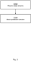
- Fig. 3 is a flowchart illustrating embodiments of a method for handling time shifted data streams in a substation network 100a, 100b.
- the method is performed by the IED 200.
- the methods are advantageously provided as computer programs 720.
- the IED 200 receives a respective data stream from at least two time synchronized data sources 120a, 120b, 120c in the substation network 100a, 100b.
- the blocking of the protection function 130 starts when the IED 200 detects that at least one data stream contains time shifted data.
- the protection function 130 is directly blocked when such a time shift is detected
- the IED 200 blocks, upon detecting a time shift between the data streams resulting from one of the data sources 120a, 120b, 120c losing its time synchronization and until a configured time amount has expired, the protection function 130 in the substation network 100a, 100b from acting on the data streams.
- the configured time amount is dependent on a clock domain hierarchy of the data sources 120a, 120b, 120c in the substation network 100a, 100b. Examples of this will be disclosed below.
- Embodiments relating to further details of handling time shifted data streams in a substation network 100a, 100b as performed by the IED 200 will now be disclosed.
- the blocking By detecting when any data source 120a, 120b, 120c shifts time, the blocking can cover lost data from any data source 120a, 120b, 120c.
- the blocking is set to last so long after the time shift has been detected such that that all other data sources has at least started their time shift and therefore their time shift can be detected by the protection function 130.
- the blocking can be removed when all data sources 120a, 120b, 120c are time synchronized from the same time source 110a, 110b.
- a data source 120a, 120b, 120c shifts time there is either a jump in time of the samples or the data stream comprises an indication that it is without time synchronization.
- the time shift might thus be detected either by that the data streams become unsynchronized or there is a jump in sample count in the data streams. That is, in some aspects the time shift is detected by that the data streams become timewise mutually unsynchronized or there is a jump in sample count in the data stream from at least one, but not all, of the data sources 120a, 120b, 120c. With this information the IED 200 is enabled detect that there is a time shift between the data streams.
- the clock domain hierarchy defines an order according to which the data sources 120a, 120b, 120c are time synchronized by at least one time source 110a, 110b in the substation network 100a, 100b. Further aspects of this will be disclosed next.
- At least two of the data sources 120a, 120b, 120c are time synchronized from respective different time sources 110a, 110b.
- the protection function 130 is blocked as long as it might take to start the time resynchronization of all other data sources.
- Fig. 4 illustrating the duration of the blocking of the protection function 130 according to a first example.
- MU1 is first time synchronized, then MU2, and then finally MU3.
- time it takes to time synchronize MU1 corresponds to 410a
- time it takes to time synchronize MU2 corresponds to 410b
- time it takes to time synchronize MU3 corresponds to 410c
- 410c is equivalent to x3 amounts of time units (that could be given in units of seconds or minutes).
- an extra block time 420a, 420b is appended for MU1 and MU2 (and optionally an extra block time 420c for MU3).
- x2 that could be given in units of seconds or minutes
- x1 that could be given in units of seconds or minutes
- the protection function 130 is blocked an extra time 420a, 420b.
- This extra time 420a, 420b is long enough so that the time synchronization has time to propagate from one data source to another.
- the extra blocking time 420a, 420b might be the same for all data streams and depend on the propagation time for the time synchronization in the substation network 100a, 100b.
- the clock domain hierarchy it takes at most x3 amounts of time units for each data source 120a, 120b, 120c to regain time synchronization, it takes x2 amounts of time units for the time synchronization to propagate to all data sources 120a, 120b, 120c, and the configured time amount expires x2 amounts of time units after time synchronization is regained for the data sources 120a, 120b, 120c.
- Fig. 4 One example of the maximum value for each data source 120a, 120b, 120c to regain time synchronization is given in IEC 61850-9-3.
- all data sources 120a, 120b, 120c are, from one and the same global time source 110a, time synchronized within x3 amounts of time units. This is illustrated in Fig. 5 .
- Fig. 5 illustrating the duration of the blocking of the protection function 130 according to a second example.
- MU1, MU2, and MU3 are time synchronized in parallel.
- the extra blocking time 420a, 420b, 420c might therefore be removed.
- the time it takes to time synchronize MU1 corresponds to 410a
- the time it takes to time synchronize MU2 corresponds to 410b
- the time it takes to time synchronize MU3 corresponds to 410c, being equivalent to x3 amounts of time units.
- all data sources 120a, 120b, 120c are locally time synchronized within the x3 amounts of time units and have the same global time source 110a, the time synchronization of all data source 120a, 120b, 120c starts simultaneously, and the configured time amount expires when x3 amounts of time units have elapsed. This is illustrated in Fig. 5 .
- the extra blocking time 420a, 420b can thus be shortened, or even removed (as in the example of Fig. 5 ), if all time sources 110a, 110b are globally time synchronized, or all time sources 110a, 110b are locally time synchronized and have the same grand master clock.
- each data stream comprises information about the time source used by the data source 120a, 120b, 120c from which the data stream originates
- the blocking of the protection function 130 might be removed as soon as all data sources 120a, 120b, 120c have the same time source. That is, in some aspects, according to the clock domain hierarchy, when each data stream comprises information identifying the time source 110a, 110b of its data source 120a, 120b, 120c, the configured time amount expires when the information of all data streams identifies one and the same time source 110a, 110b.
- the time source can be either a common time source or that all time sources 110a, 110b are time synchronized to a global time.
- time source 110a is used to provide time synchronization of all the data sources 120a, 120b, 120c to global time. It is then assumed that the time source 110a experiences a failure, potentially causing one or more of the data sources 120a, 120b, 120c to lose its time synchronization to the global time.
- the IED 200 by means of its time source 110b, then performs time synchronization of all the data sources 120a, 120b, 120c to local time. However, after some time, the time source 110b might drift away from the global time.
- the time source 110a is then repaired and starts to send time synchronization messages to the data sources 120a, 120b, 120c (as well as to the IED 200).
- data source 120a (as representing MU1) and the IED 200 (including the protection function 130) start to time synchronize to the new global time.
- data sources 120a, 120b (representing MU2 and MU3) are still on the local time.
- MU1 shifts time and starts to send a data stream towards the protection function 130 with the new time
- MU2 and MU3 still send data streams towards the protection function 130 with the old time. Without any blocking of the protection function 130, this situation is likely to cause the protection function 130 to trigger the circuit breaker to trip.
- the protection function 130 is blocked an extra time after the IED 200 has detected a time shift in one of the data streams. During this time the new time can propagate to MU2 and MU3, so they can report to the IED 200 that they are out of time synchronization and start to be time synchronized again.
- the protection function 130 is by the IED 200 blocked during the time shift for MU2 and MU3 (and, optionally, for an extra blocking time). The extra blocking time might be reduced when all MUs report global synchronized data or if all MUs are locally synchronized and identifies one the same time source.
- Fig. 6 schematically illustrates, in terms of a number of functional units, the components of an IED 200 according to an embodiment.
- Processing circuitry 210 is provided using any combination of one or more of a suitable central processing unit (CPU), multiprocessor, microcontroller, digital signal processor (DSP), etc., capable of executing software instructions stored in a computer program product 310 (as in Fig. 7 ), e.g. in the form of a storage medium 230.
- the processing circuitry 210 may further be provided as at least one application specific integrated circuit (ASIC), or field programmable gate array (FPGA).
- ASIC application specific integrated circuit
- FPGA field programmable gate array
- the processing circuitry 210 is configured to cause the IED 200 to perform a set of operations, or actions, as disclosed above.
- the storage medium 230 may store the set of operations
- the processing circuitry 210 may be configured to retrieve the set of operations from the storage medium 230 to cause the IED 200 to perform the set of operations.
- the set of operations may be provided as a set of executable instructions.
- the processing circuitry 210 is thereby arranged to execute methods as herein disclosed.
- the storage medium 230 may also comprise persistent storage, which, for example, can be any single one or combination of magnetic memory, optical memory, solid state memory or even remotely mounted memory.
- the IED 200 may further comprise a communications interface 220 at least configured for communications with other entities, functions, nodes, and devices of the substation network 100a, 100b.
- the communications interface 220 may comprise one or more transmitters and receivers, comprising analogue and digital components.
- the processing circuitry 210 controls the general operation of the IED 200 e.g. by sending data and control signals to the communications interface 220 and the storage medium 230, by receiving data and reports from the communications interface 220, and by retrieving data and instructions from the storage medium 230.
- a protection function 130 is part of, integrated with, or collocated with, the IED 200. Hence, in some aspects the IED further comprises the protection function 130.
- IED 200 Other components, as well as the related functionality, of the IED 200 are omitted in order not to obscure the concepts presented herein.
- Fig. 7 shows one example of a computer program product 310 comprising computer readable storage medium 330.
- a computer program 320 can be stored, which computer program 320 can cause the processing circuitry 210 and thereto operatively coupled entities and devices, such as the communications interface 220 and the storage medium 230, to execute methods according to embodiments described herein.
- the computer program 320 and/or computer program product 310 may thus provide means for performing any action as herein disclosed.
- the computer program product 310 is illustrated as an optical disc, such as a CD (compact disc) or a DVD (digital versatile disc) or a Blu-Ray disc.
- the computer program product 310 could also be embodied as a memory, such as a random access memory (RAM), a read-only memory (ROM), an erasable programmable read-only memory (EPROM), or an electrically erasable programmable read-only memory (EEPROM) and more particularly as a non-volatile storage medium of a device in an external memory such as a USB (Universal Serial Bus) memory or a Flash memory, such as a compact Flash memory.
- the computer program 320 is here schematically shown as a track on the depicted optical disk, the computer program 320 can be stored in any way which is suitable for the computer program product 310.
Landscapes
- Engineering & Computer Science (AREA)
- Power Engineering (AREA)
- Physics & Mathematics (AREA)
- Electromagnetism (AREA)
- General Physics & Mathematics (AREA)
- Emergency Protection Circuit Devices (AREA)
- Synchronisation In Digital Transmission Systems (AREA)
- Remote Monitoring And Control Of Power-Distribution Networks (AREA)
- Electric Clocks (AREA)
Description
- Embodiments presented herein relate to a method, an intelligent electronic device (IED), a computer program, and a computer program product for handling time shifted data streams caused by lost time synchronization in a substation network.
- In general terms, substations are part of an electrical generation, transmission, and distribution system. Substations act as connection points between different transmission lines of the electrical system and might additionally transform voltage from high to low, or the reverse, or perform any of several other functions. Between the generating station and consumer, electric power may flow through several substations at different voltage levels. A substation may include transformers to change voltage levels between high transmission voltages and lower distribution voltages, or at the interconnection of two different transmission voltages.
- In general terms, substations are often unattended, relying on remote supervision and control. In this respect, data streams from different data sources within a substation may be fed to a protection function configured to, based on the data streams, make a trip decision and thus to determine whether or not to trip a circuit breaker.
- In general terms, for protections functions whose trip decision depends on data streams from several data sources, the data streams need to be time correlated. A precise and unified time synchronization of the data sources is thus required for the protection function to work properly. In systems where the time synchronization is propagated in a hierarchical manner (e.g. a system with multiple subnetworks interconnected with boundary clocks and using the precision time protocol, PTP, or its profile subset IEC 61850-9-3) a time shift in the time source (or a switch of time source) may imply a substantial propagation delay of the time shift throughout the system within the substation. In turn, this might lead to transient time differences between the data sources that can lead to miss-operations of the protection function. If the data streams received by the protection function cannot be guaranteed to be time correlated the protection function should therefore be blocked such that false trips are avoided.
- However, there is still a need for an improving the performance of the protection function in substation networks.
-
US 2011/0063766 A1 discloses a line current differential protection system that uses an external time reference and that continues providing protection to a power apparatus upon the loss of the external time reference.US 2011/0063766 A1 discloses that an external time reference synchronization mode and a channel based synchronization mode may be selectively applied on a per channel basis such that only those channels in the system that are not guaranteed to stay symmetrical use external time reference synchronization.US 2011/0063766 A1 further discloses that when the external time reference is lost, fallback strategies may be used such as disabling or de-sensitizing the line current differential protection function, switching from the external time reference synchronization mode to a channel based synchronization mode with appropriately selected protection settings, and/or marking the channel as unavailable to isolate the system from the consequences of synchronization errors over this channel and instead using a master-slave mode with other available channels to continue providing line protection with the current differential system. - An object of embodiments herein is to provide efficient mechanisms for handling time shifted data streams in a substation network that can be used to improve the performance of the protection function.
- According to a first aspect there is presented a method for handling time shifted data streams in a substation network. The method is performed by an IED. The method comprises receiving a respective data stream from at least two time synchronized data sources in the substation network. The method comprises blocking, upon detecting a time shift between the data streams resulting from one of the data sources losing its time synchronization and until a configured time amount has expired, a protection function in the substation network from acting on the data streams. The configured time amount is dependent on a clock domain hierarchy of the data sources in the substation network.
- According to a second aspect there is presented an IED for handling time shifted data streams in a substation network. The IED comprises processing circuitry. The processing circuitry is configured to cause the IED to receive a respective data stream from at least two time synchronized data sources in the substation network. The processing circuitry is configured to cause the IED to block, upon detecting a time shift between the data streams resulting from one of the data sources losing its time synchronization and until a configured time amount has expired, a protection function in the substation network from acting on the data streams. The configured time amount is dependent on a clock domain hierarchy of the data sources in the substation network.
- According to a third aspect there is presented a computer program for handling time shifted data streams in a substation network, the computer program comprising computer program code which, when run on an IED, causes the IED to perform a method according to the first aspect.
- According to a fourth aspect there is presented a computer program product comprising a computer program according to the third aspect and a computer readable storage medium on which the computer program is stored. The computer readable storage medium could be a non-transitory computer readable storage medium.
- Advantageously this provides efficient blocking of the protection function when the data sources are without time synchronization.
- Advantageously this provides efficient blocking of the protection function as long as necessary.
- Advantageously this enables better utilization of the protection function, but still avoids any false trips.
- Other objectives, features and advantages of the enclosed embodiments will be apparent from the following detailed disclosure, from the attached dependent claims as well as from the drawings.
- Generally, all terms used in the claims are to be interpreted according to their ordinary meaning in the technical field, unless explicitly defined otherwise herein. All references to "a/an/the element, apparatus, component, means, module, action, etc." are to be interpreted openly as referring to at least one instance of the element, apparatus, component, means, module, action, etc., unless explicitly stated otherwise. The actions of any method disclosed herein do not have to be performed in the exact order disclosed, unless explicitly stated.
- The inventive concept is now described, by way of example, with reference to the accompanying drawings, in which:
-
Figs. 1 and 2 are schematic diagrams illustrating substation networks according to embodiments; -
Fig. 3 is a flowchart of a method according to an embodiment; -
Figs. 4 and 5 schematically illustrate duration of blocking of a protection function according to according to embodiments; -
Fig. 6 is a schematic diagram showing functional units of an IED according to an embodiment; and -
Fig. 7 shows one example of a computer program product comprising computer readable storage medium according to an embodiment. - The inventive concept will now be described more fully hereinafter with reference to the accompanying drawings, in which certain embodiments of the inventive concept are shown. This inventive concept may, however, be embodied in many different forms and should not be construed as limited to the embodiments set forth herein; rather, these embodiments are provided by way of example so that this disclosure will be thorough and complete, and will fully convey the scope of the inventive concept to those skilled in the art. Like numbers refer to like elements throughout the description. Any action or feature illustrated by dashed lines should be regarded as optional.
-
Fig. 1 is a schematic diagram illustrating asubstation network 100a where embodiments presented herein can be applied. Thesubstation network 100a comprisesdata sources data sources protection function 130. Eachdata source respective merging unit Figs. 4 and 5 ) of asubstation 160 in thesubstation network 100a. - The
protection function 130 is part of, integrated with, or collocated with, an IED 200. There could be different examples of protection functions. In some examples theprotection function 130 is a relay protection function or a control function, such as a synchronization check function. Thedata sources MUs protection function 130 via aprocess bus 150. Each data stream might thus comprise analog samples, for example representing voltage or current measurements ofMUs substation network - The
data sources time source 110a, which might act as a grand master clock for thesubstation network 100a. -
Fig. 2 is a schematic diagram illustrating asubstation network 100b where embodiments presented herein can be applied. Thesubstation network 100b comprises the same components as thesubstation network 100a. In addition thereto, afurther time source 110b is provided in the form of a boundary clock. InFig. 2 the boundary clock is physically separated from theIED 200; thesubstation network 100a might also comprises a boundary clock that might be integrated with, or collocated with, theIED 200. - As disclosed above, data streams from
data sources protection function 130 for making a trip decision. As further disclosed above, there is a need for improving the performance of theprotection function 130. - In more detail, when there is a time shift (such as a change of reference time) in the
substation network data sources new time source substation network - When the data sources of the substation is time synchronized via PTP (or IEC 61850-9-3), the new time will ripple from the clock through the
substation network data source substation network - As a non-limiting illustrative example, assume with reference to
Fig. 1 or Fig, 2 , that thetime source 110a experiences a failure causing it to lose time synchronization for some time and then regains reliable time synchronization from, for example, a satellite system (not shown). The correct time will thus reach MU1 and the IED 200 (including the protection function 130) first. Then, the correct time will propagate to MU2 and MU3 through theboundary clock 110b (either provided inside theIED 200 as inFig. 1 or as a separate entity as inFig. 2 ). This means that for a short duration, MU2 and MU3 will both appear to be time synchronized, but they will in practice have different time compared to MU1 and the IED 200 (including the protection function 130). Therefore, if theprotection function 130 is not blocked during this situation, a false trip might be triggered by theprotection function 130. The blocking of theprotection function 130 can be stopped when all devices (IED and MUs) are time synchronized from the same time source. - As this illustrative example shows, when the time shift occurs the data streams from the
different data sources protection function 130 which causes a trip to be triggered, even if there is no fault in any of the MUs 140a, 140b, 140c, or parts thereof. As noted above, this issue can be mitigated by blocking theprotection function 130 during these situations. However, it might be cumbersome to determine when to start blocking of theprotection function 130 and for how long the duration of the blocking should last. Otherwise there is a potential risk that the time duration for which theprotection function 130 is blocked is either too short (leading to potential false trips), or too long (leading to potentially missing registering a true differential current at theprotection function 130, which causes a true trip to be missed). - One way is to block the
protection function 130 when theprotection function 130 itself detects a time shift in the data streams. However, this does not help if one or more of thedata sources protection function 130. - Another way is to include information to what master time source each
data source data sources data sources data sources - Further, if a system loses the clock and another time source in the system takes the roles as grand master clock, the changeover will not take place at the same time for all
data sources - According to the herein disclosed embodiments there is provided mechanisms that prevent the miss operations (e.g. by blocking the protection function 130) during the propagation of the time shift. Also, mechanisms are provided to limit the blocking of the
protection function 130 as much as possible, but still prevent false trips (i.e., trips without any reason in thesubstation network - This is achieved by blocking the
protection function 130 when needed but limit the time as much as possible as well as avoid blocking theprotection function 130 when not needed. - The embodiments disclosed herein in particular relate to mechanisms for handling time shifted data streams in a
substation network IED 200, a method performed by theIED 200, a computer program product comprising code, for example in the form of a computer program, that when run on anIED 200, causes theIED 200 to perform the method. -
Fig. 3 is a flowchart illustrating embodiments of a method for handling time shifted data streams in asubstation network IED 200. The methods are advantageously provided ascomputer programs 720. - S102: The
IED 200 receives a respective data stream from at least two time synchronizeddata sources substation network - The blocking of the
protection function 130 starts when theIED 200 detects that at least one data stream contains time shifted data. Theprotection function 130 is directly blocked when such a time shift is detected - S104: The
IED 200 blocks, upon detecting a time shift between the data streams resulting from one of thedata sources protection function 130 in thesubstation network - The configured time amount is dependent on a clock domain hierarchy of the
data sources substation network - Embodiments relating to further details of handling time shifted data streams in a
substation network IED 200 will now be disclosed. - By detecting when any
data source data source protection function 130. To optimize the duration of the blocking, the blocking can be removed when alldata sources same time source - In general terms, when a
data source data sources IED 200 is enabled detect that there is a time shift between the data streams. - In some aspects the clock domain hierarchy defines an order according to which the
data sources time source substation network - In some aspects, according to the clock domain hierarchy, at least two of the
data sources different time sources - Since the time adjustment of all
time sources protection function 130 is blocked as long as it might take to start the time resynchronization of all other data sources. - Reference is now made to
Fig. 4 illustrating the duration of the blocking of theprotection function 130 according to a first example. Here it is assumed that MU1 is first time synchronized, then MU2, and then finally MU3. It is further assumed that the time it takes to time synchronize MU1 corresponds to 410a, the time it takes to time synchronize MU2 corresponds to 410b, and the time it takes to time synchronize MU3 corresponds to 410c, where 410c is equivalent to x3 amounts of time units (that could be given in units of seconds or minutes). It is further assumed that anextra block time extra block time 420c for MU3). It is further assumed that it takes x2 amounts of time units (that could be given in units of seconds or minutes) for the time synchronization to start for MU3 after the time synchronization has started at MU1. The total amount of time units that MU1 causes theprotection function 130 to be blocked is denoted x1 (that could be given in units of seconds or minutes) and is thus equal to the combination of the time it takes to time synchronize MU1 (corresponding to 410a) and theextra block time 420a. - That is, when the data stream starts to deliver time synchronized data again, the
protection function 130 is blocked anextra time extra time extra blocking time substation network protection function 130 will continue. - In some aspects, according to the clock domain hierarchy, it takes at most x3 amounts of time units for each
data source data sources data sources Fig. 4 . One example of the maximum value for eachdata source - In other aspects, according to the clock domain hierarchy, all
data sources global time source 110a, time synchronized within x3 amounts of time units. This is illustrated inFig. 5 . - Reference is now made to
Fig. 5 illustrating the duration of the blocking of theprotection function 130 according to a second example. - Here it is assumed that MU1, MU2, and MU3 are time synchronized in parallel. The
extra blocking time - In some aspects, according to the clock domain hierarchy, all
data sources global time source 110a, the time synchronization of alldata source Fig. 5 . - The
extra blocking time Fig. 5 ), if alltime sources time sources - If each data stream comprises information about the time source used by the
data source protection function 130 might be removed as soon as alldata sources time source data source same time source time sources - One particular embodiment for handling time shifted data streams in a
substation network substation networks - It is assumed that under normal operation, the
time source 110a is used to provide time synchronization of all thedata sources time source 110a experiences a failure, potentially causing one or more of thedata sources - The
IED 200, by means of itstime source 110b, then performs time synchronization of all thedata sources time source 110b might drift away from the global time. - The
time source 110a is then repaired and starts to send time synchronization messages to thedata sources data source 120a (as representing MU1) and the IED 200 (including the protection function 130) start to time synchronize to the new global time. However,data sources protection function 130 with the new time, MU2 and MU3 still send data streams towards theprotection function 130 with the old time. Without any blocking of theprotection function 130, this situation is likely to cause theprotection function 130 to trigger the circuit breaker to trip. - To avoid this erroneous trip to occur, the
protection function 130 is blocked an extra time after theIED 200 has detected a time shift in one of the data streams. During this time the new time can propagate to MU2 and MU3, so they can report to theIED 200 that they are out of time synchronization and start to be time synchronized again. Theprotection function 130 is by theIED 200 blocked during the time shift for MU2 and MU3 (and, optionally, for an extra blocking time). The extra blocking time might be reduced when all MUs report global synchronized data or if all MUs are locally synchronized and identifies one the same time source. -
Fig. 6 schematically illustrates, in terms of a number of functional units, the components of anIED 200 according to an embodiment.Processing circuitry 210 is provided using any combination of one or more of a suitable central processing unit (CPU), multiprocessor, microcontroller, digital signal processor (DSP), etc., capable of executing software instructions stored in a computer program product 310 (as inFig. 7 ), e.g. in the form of astorage medium 230. Theprocessing circuitry 210 may further be provided as at least one application specific integrated circuit (ASIC), or field programmable gate array (FPGA). - Particularly, the
processing circuitry 210 is configured to cause theIED 200 to perform a set of operations, or actions, as disclosed above. For example, thestorage medium 230 may store the set of operations, and theprocessing circuitry 210 may be configured to retrieve the set of operations from thestorage medium 230 to cause theIED 200 to perform the set of operations. The set of operations may be provided as a set of executable instructions. - Thus the
processing circuitry 210 is thereby arranged to execute methods as herein disclosed. Thestorage medium 230 may also comprise persistent storage, which, for example, can be any single one or combination of magnetic memory, optical memory, solid state memory or even remotely mounted memory. TheIED 200 may further comprise acommunications interface 220 at least configured for communications with other entities, functions, nodes, and devices of thesubstation network communications interface 220 may comprise one or more transmitters and receivers, comprising analogue and digital components. Theprocessing circuitry 210 controls the general operation of theIED 200 e.g. by sending data and control signals to thecommunications interface 220 and thestorage medium 230, by receiving data and reports from thecommunications interface 220, and by retrieving data and instructions from thestorage medium 230. - As disclosed above, a
protection function 130 is part of, integrated with, or collocated with, theIED 200. Hence, in some aspects the IED further comprises theprotection function 130. - Other components, as well as the related functionality, of the
IED 200 are omitted in order not to obscure the concepts presented herein. -
Fig. 7 shows one example of a computer program product 310 comprising computer readable storage medium 330. On this computer readable storage medium 330, a computer program 320 can be stored, which computer program 320 can cause theprocessing circuitry 210 and thereto operatively coupled entities and devices, such as thecommunications interface 220 and thestorage medium 230, to execute methods according to embodiments described herein. The computer program 320 and/or computer program product 310 may thus provide means for performing any action as herein disclosed. - In the example of
Fig. 7 , the computer program product 310 is illustrated as an optical disc, such as a CD (compact disc) or a DVD (digital versatile disc) or a Blu-Ray disc. The computer program product 310 could also be embodied as a memory, such as a random access memory (RAM), a read-only memory (ROM), an erasable programmable read-only memory (EPROM), or an electrically erasable programmable read-only memory (EEPROM) and more particularly as a non-volatile storage medium of a device in an external memory such as a USB (Universal Serial Bus) memory or a Flash memory, such as a compact Flash memory. Thus, while the computer program 320 is here schematically shown as a track on the depicted optical disk, the computer program 320 can be stored in any way which is suitable for the computer program product 310. - The inventive concept has mainly been described above with reference to a few embodiments. However, as is readily appreciated by a person skilled in the art, other embodiments than the ones disclosed above are equally possible within the scope of the inventive concept, as defined by the appended patent claims.
Claims (15)
- A method for handling time shifted data streams in a substation network (100a, 100b), the method being performed by an intelligent electronic device, IED (200), the method comprising:receiving (S102) a respective data stream from at least two time synchronized data sources (120a, 120b, 120c) in the substation network (100a, 100b);the method being characterized by:blocking (S104), upon detecting a time shift between the data streams resulting from one of the data sources (120a, 120b, 120c) losing its time synchronization and until a configured time amount has expired, a protection function (130) in the substation network (100a, 100b) from acting on the data streams,wherein the configured time amount is dependent on a clock domain hierarchy of the data sources (120a, 120b, 120c) in the substation network (100a, 100b).
- The method according to claim 1, wherein the clock domain hierarchy defines an order according to which the data sources (120a, 120b, 120c) are time synchronized by at least one time source (110a, 110b) in the substation network (100a, 100b).
- The method according to claim 1, wherein according to the clock domain hierarchy at least two of the data sources (120a, 120b, 120c) are time synchronized from respective different time sources (110a, 110b).
- The method according to claim 3, wherein according to the clock domain hierarchy it takes at most x3 amounts of time units for each data source (120a, 120b, 120c) to regain time synchronization, wherein it takes x2 amounts of time units for the time synchronization to propagate to all data sources (120a, 120b, 120c), and wherein the configured time amount expires x2 amounts of time units after time synchronization is regained for the data sources (120a, 120b, 120c).
- The method according to claim 1, wherein according to the clock domain hierarchy all data sources (120a, 120b, 120c) are, from one and the same global time source (110a), time synchronized within x3 amounts of time units.
- The method according to claim 5, wherein according to the clock domain hierarchy all data sources (120a, 120b, 120c) are locally time synchronized within the x3 amounts of time units and have the same global time source (110a), wherein the time synchronization of all data source (120a, 120b, 120c) starts simultaneously, and wherein the configured time amount expires when x3 amounts of time units have elapsed.
- The method according to claim 1, wherein, according to the clock domain hierarchy, when each data stream comprises information identifying the time source (110a, 110b) of its data source (120a, 120b, 120c), the configured time amount expires when the information of all data streams identifies one and the same time source (110a, 110b).
- The method according to claim 1, wherein the time shift is detected by that the data streams become timewise mutually unsynchronized or there is a jump in sample count in the data stream from at least one, but not all, of the data sources (120a, 120b, 120c).
- The method according to any of the preceding claims, wherein all data source (120a, 120b, 120c) belongs to a respective merging units (140a, 140b, 140c) of a substation (160) in the substation network (100a, 100b).
- The method according to any of the preceding claims, wherein each data stream comprises analog samples, for example representing voltage or current measurements of merging units (140a, 140b, 140c) of a substation (160) in the substation network (100a, 100b).
- The method according to any of the preceding claims, wherein the protection function (130) is a relay protection function.
- An intelligent electronic device, IED (200) for handling time shifted data streams in a substation network (100a, 100b), the IED (200) comprising processing circuitry (210), the processing circuitry being configured to cause the IED (200) to:receive a respective data stream from at least two time synchronized data sources (120a, 120b, 120c) in the substation network (100a, 100b);the IED being characterized in that the processing circuitry is configured to cause the IED to:block, upon detecting a time shift between the data streams resulting from one of the data sources (120a, 120b, 120c) losing its time synchronization and until a configured time amount has expired, a protection function (130) in the substation network (100a, 100b) from acting on the data streams,wherein the configured time amount is dependent on a clock domain hierarchy of the data sources (120a, 120b, 120c) in the substation network (100a, 100b).
- The IED (200) according to claim 12, further being configured to perform the method according to any of claims 2 to 11.
- A computer program (320) for handling time shifted data streams in a substation network (100a, 100b), the computer program comprising computer code which, when run on processing circuitry (210) of an intelligent electronic device, IED (200), causes the IED (200) to:receive (S102) a respective data stream from at least two time synchronized data sources (120a, 120b, 120c) in the substation network (100a, 100b);the computer program being characterized in that the computer code, when run on the processing circuitry of the IED, causes the IED to:block (S104), upon detecting a time shift between the data streams resulting from one of the data sources (120a, 120b, 120c) losing its time synchronization and until a configured time amount has expired, a protection function (130) in the substation network (100a, 100b) from acting on the data streams,wherein the configured time amount is dependent on a clock domain hierarchy of the data sources (120a, 120b, 120c) in the substation network (100a, 100b).
- A computer program product (310) comprising a computer program (320) according to claim 14, and a computer readable storage medium (330) on which the computer program is stored.
Priority Applications (6)
| Application Number | Priority Date | Filing Date | Title |
|---|---|---|---|
| EP19169478.5A EP3726678B1 (en) | 2019-04-16 | 2019-04-16 | Handling of lost time synchronization in a substation network |
| PL19169478.5T PL3726678T3 (en) | 2019-04-16 | 2019-04-16 | Handling of lost time synchronization in a substation network |
| US17/441,487 US12166350B2 (en) | 2019-04-16 | 2020-04-14 | Handling of lost time synchronization in a substation network |
| JP2021561840A JP7361793B2 (en) | 2019-04-16 | 2020-04-14 | Handling lost time synchronization in substation networks |
| CN202080028217.7A CN113692682B (en) | 2019-04-16 | 2020-04-14 | Dealing with lost time synchronization in substation networks |
| PCT/EP2020/060373 WO2020212300A1 (en) | 2019-04-16 | 2020-04-14 | Handling of lost time synchronization in a substation network |
Applications Claiming Priority (1)
| Application Number | Priority Date | Filing Date | Title |
|---|---|---|---|
| EP19169478.5A EP3726678B1 (en) | 2019-04-16 | 2019-04-16 | Handling of lost time synchronization in a substation network |
Publications (3)
| Publication Number | Publication Date |
|---|---|
| EP3726678A1 EP3726678A1 (en) | 2020-10-21 |
| EP3726678B1 true EP3726678B1 (en) | 2023-08-09 |
| EP3726678C0 EP3726678C0 (en) | 2023-08-09 |
Family
ID=66217758
Family Applications (1)
| Application Number | Title | Priority Date | Filing Date |
|---|---|---|---|
| EP19169478.5A Active EP3726678B1 (en) | 2019-04-16 | 2019-04-16 | Handling of lost time synchronization in a substation network |
Country Status (6)
| Country | Link |
|---|---|
| US (1) | US12166350B2 (en) |
| EP (1) | EP3726678B1 (en) |
| JP (1) | JP7361793B2 (en) |
| CN (1) | CN113692682B (en) |
| PL (1) | PL3726678T3 (en) |
| WO (1) | WO2020212300A1 (en) |
Family Cites Families (17)
| Publication number | Priority date | Publication date | Assignee | Title |
|---|---|---|---|---|
| US4225960A (en) * | 1979-03-01 | 1980-09-30 | Westinghouse Electric Corp. | Automatic synchronizing system for digital asynchronous communications |
| JPH1042448A (en) * | 1996-07-18 | 1998-02-13 | Hitachi Ltd | Digital protection controller |
| US7630863B2 (en) * | 2006-09-19 | 2009-12-08 | Schweitzer Engineering Laboratories, Inc. | Apparatus, method, and system for wide-area protection and control using power system data having a time component associated therewith |
| MX2010002163A (en) | 2007-09-28 | 2010-06-02 | Schweitzer Engineering Lab Inc | Amplitude and phase comparators for line protection. |
| US8401007B2 (en) | 2009-04-06 | 2013-03-19 | Avaya Inc. | Network synchronization over IP networks |
| BR112012002904A2 (en) | 2009-08-10 | 2016-04-05 | Scweitzer Engineering Lab Inc | system and method for controlling an electrical distribution system, and intelligent, electronic device |
| US8154836B2 (en) * | 2009-09-17 | 2012-04-10 | Schweitzer Engineering Laboratories, Inc. | Line current differential protection upon loss of an external time reference |
| JP5507025B1 (en) | 2012-06-26 | 2014-05-28 | 三菱電機株式会社 | Current differential relay |
| CN102801557B (en) * | 2012-07-27 | 2016-08-10 | 中国电力科学研究院 | A kind of system approach improving substation network sampling reliability |
| BR112015008592A2 (en) * | 2012-10-19 | 2017-07-04 | Schweitzer Engineering Lab Inc | method, time distribution device, and non-temporary computer readable storage media |
| JP6186978B2 (en) | 2013-07-23 | 2017-08-30 | 富士電機株式会社 | Protection monitoring control system |
| WO2015063815A1 (en) * | 2013-10-31 | 2015-05-07 | 三菱電機株式会社 | Signal processing device |
| EP3136528B1 (en) * | 2015-08-31 | 2020-04-22 | Siemens Aktiengesellschaft | Differential protection method, differential protection device and differential protection system |
| US10637802B2 (en) * | 2016-07-28 | 2020-04-28 | General Electric Technology Gmbh | Systems and methods for network failover in digital substations |
| US20180109369A1 (en) | 2016-10-14 | 2018-04-19 | General Electric Technology Gmbh | Systems and methods for synchronizing time sources within a protection zone of a digital power substation |
| SE1651596A1 (en) * | 2016-12-05 | 2016-12-30 | Abb Schweiz Ag | Time synchronization of intelligent electronic devices |
| JP2018117227A (en) | 2017-01-18 | 2018-07-26 | 株式会社明電舎 | Time synchronization method |
-
2019
- 2019-04-16 PL PL19169478.5T patent/PL3726678T3/en unknown
- 2019-04-16 EP EP19169478.5A patent/EP3726678B1/en active Active
-
2020
- 2020-04-14 JP JP2021561840A patent/JP7361793B2/en active Active
- 2020-04-14 US US17/441,487 patent/US12166350B2/en active Active
- 2020-04-14 CN CN202080028217.7A patent/CN113692682B/en active Active
- 2020-04-14 WO PCT/EP2020/060373 patent/WO2020212300A1/en not_active Ceased
Also Published As
| Publication number | Publication date |
|---|---|
| CN113692682A (en) | 2021-11-23 |
| JP7361793B2 (en) | 2023-10-16 |
| US20220181878A1 (en) | 2022-06-09 |
| PL3726678T3 (en) | 2024-01-29 |
| JP2022529049A (en) | 2022-06-16 |
| WO2020212300A1 (en) | 2020-10-22 |
| CN113692682B (en) | 2024-09-27 |
| EP3726678A1 (en) | 2020-10-21 |
| EP3726678C0 (en) | 2023-08-09 |
| US12166350B2 (en) | 2024-12-10 |
Similar Documents
| Publication | Publication Date | Title |
|---|---|---|
| US9042412B2 (en) | Method and apparatus for detecting communication channel delay asymmetry | |
| JP2018091828A (en) | System and method for synchronization of time source in protective zone of digital electric power substation | |
| CN103592842A (en) | Intelligent substation clock synchronization reliability method capable of improving network sampling | |
| US8392730B2 (en) | Current sharing method of DC power supply and device thereof | |
| CN106788838B (en) | A system and method for robust control of power time synchronization system | |
| CN110795289B (en) | Multi-clock automatic switching method | |
| EP3726678B1 (en) | Handling of lost time synchronization in a substation network | |
| Falahati et al. | Failure modes in IEC 61850-enabled substation automation systems | |
| US20130266053A1 (en) | Signal selecting circuit and signal selecting method | |
| US12003087B2 (en) | Time synchronization between IEDs of different substations | |
| CN110995336A (en) | OLP transmission link switching method and device, storage medium and OLP | |
| CN106647228A (en) | Convertor station master clock fault determination system | |
| JP5312372B2 (en) | Equipment monitoring device and equipment monitoring system | |
| CN113156268A (en) | Voltage time type or current type based fault positioning method, device and equipment | |
| JP5844022B1 (en) | Process bus application protection system | |
| CN120883542A (en) | Methods for synchronizing smart electronic devices in local restricted networks | |
| US7418036B2 (en) | Method and circuit for timing pulse generation | |
| Kasztenny et al. | Fallback algorithms for line current differential protection applied with asymmetrical channels upon the loss of time reference | |
| CN104052564A (en) | Method and device for detecting channel delay asymmetry | |
| JP2026513835A (en) | A method for synchronizing intelligent electronic units in a locally limited network. | |
| CN121809369A (en) | Clock path switching method and device based on PTP clock redundancy path | |
| KR20120017927A (en) | Receive data compensation method | |
| JPH01259644A (en) | Clock reception circuit |
Legal Events
| Date | Code | Title | Description |
|---|---|---|---|
| PUAI | Public reference made under article 153(3) epc to a published international application that has entered the european phase |
Free format text: ORIGINAL CODE: 0009012 |
|
| STAA | Information on the status of an ep patent application or granted ep patent |
Free format text: STATUS: THE APPLICATION HAS BEEN PUBLISHED |
|
| AK | Designated contracting states |
Kind code of ref document: A1 Designated state(s): AL AT BE BG CH CY CZ DE DK EE ES FI FR GB GR HR HU IE IS IT LI LT LU LV MC MK MT NL NO PL PT RO RS SE SI SK SM TR |
|
| AX | Request for extension of the european patent |
Extension state: BA ME |
|
| STAA | Information on the status of an ep patent application or granted ep patent |
Free format text: STATUS: REQUEST FOR EXAMINATION WAS MADE |
|
| 17P | Request for examination filed |
Effective date: 20210421 |
|
| RBV | Designated contracting states (corrected) |
Designated state(s): AL AT BE BG CH CY CZ DE DK EE ES FI FR GB GR HR HU IE IS IT LI LT LU LV MC MK MT NL NO PL PT RO RS SE SI SK SM TR |
|
| RAP3 | Party data changed (applicant data changed or rights of an application transferred) |
Owner name: HITACHI ENERGY SWITZERLAND AG |
|
| STAA | Information on the status of an ep patent application or granted ep patent |
Free format text: STATUS: EXAMINATION IS IN PROGRESS |
|
| 17Q | First examination report despatched |
Effective date: 20220518 |
|
| GRAP | Despatch of communication of intention to grant a patent |
Free format text: ORIGINAL CODE: EPIDOSNIGR1 |
|
| STAA | Information on the status of an ep patent application or granted ep patent |
Free format text: STATUS: GRANT OF PATENT IS INTENDED |
|
| INTG | Intention to grant announced |
Effective date: 20230302 |
|
| GRAS | Grant fee paid |
Free format text: ORIGINAL CODE: EPIDOSNIGR3 |
|
| GRAA | (expected) grant |
Free format text: ORIGINAL CODE: 0009210 |
|
| STAA | Information on the status of an ep patent application or granted ep patent |
Free format text: STATUS: THE PATENT HAS BEEN GRANTED |
|
| P01 | Opt-out of the competence of the unified patent court (upc) registered |
Effective date: 20230527 |
|
| AK | Designated contracting states |
Kind code of ref document: B1 Designated state(s): AL AT BE BG CH CY CZ DE DK EE ES FI FR GB GR HR HU IE IS IT LI LT LU LV MC MK MT NL NO PL PT RO RS SE SI SK SM TR |
|
| REG | Reference to a national code |
Ref country code: GB Ref legal event code: FG4D |
|
| REG | Reference to a national code |
Ref country code: CH Ref legal event code: EP |
|
| REG | Reference to a national code |
Ref country code: IE Ref legal event code: FG4D |
|
| REG | Reference to a national code |
Ref country code: DE Ref legal event code: R096 Ref document number: 602019034391 Country of ref document: DE |
|
| U01 | Request for unitary effect filed |
Effective date: 20230830 |
|
| P04 | Withdrawal of opt-out of the competence of the unified patent court (upc) registered |
Effective date: 20230901 |
|
| U07 | Unitary effect registered |
Designated state(s): AT BE BG DE DK EE FI FR IT LT LU LV MT NL PT SE SI Effective date: 20230906 |
|
| RAP2 | Party data changed (patent owner data changed or rights of a patent transferred) |
Owner name: HITACHI ENERGY LTD |
|
| U1K | Transfer of rights of the unitary patent after the registration of the unitary effect |
Owner name: HITACHI ENERGY LTD; CH |
|
| PG25 | Lapsed in a contracting state [announced via postgrant information from national office to epo] |
Ref country code: GR Free format text: LAPSE BECAUSE OF FAILURE TO SUBMIT A TRANSLATION OF THE DESCRIPTION OR TO PAY THE FEE WITHIN THE PRESCRIBED TIME-LIMIT Effective date: 20231110 |
|
| PG25 | Lapsed in a contracting state [announced via postgrant information from national office to epo] |
Ref country code: IS Free format text: LAPSE BECAUSE OF FAILURE TO SUBMIT A TRANSLATION OF THE DESCRIPTION OR TO PAY THE FEE WITHIN THE PRESCRIBED TIME-LIMIT Effective date: 20231209 |
|
| PG25 | Lapsed in a contracting state [announced via postgrant information from national office to epo] |
Ref country code: RS Free format text: LAPSE BECAUSE OF FAILURE TO SUBMIT A TRANSLATION OF THE DESCRIPTION OR TO PAY THE FEE WITHIN THE PRESCRIBED TIME-LIMIT Effective date: 20230809 Ref country code: NO Free format text: LAPSE BECAUSE OF FAILURE TO SUBMIT A TRANSLATION OF THE DESCRIPTION OR TO PAY THE FEE WITHIN THE PRESCRIBED TIME-LIMIT Effective date: 20231109 Ref country code: IS Free format text: LAPSE BECAUSE OF FAILURE TO SUBMIT A TRANSLATION OF THE DESCRIPTION OR TO PAY THE FEE WITHIN THE PRESCRIBED TIME-LIMIT Effective date: 20231209 Ref country code: HR Free format text: LAPSE BECAUSE OF FAILURE TO SUBMIT A TRANSLATION OF THE DESCRIPTION OR TO PAY THE FEE WITHIN THE PRESCRIBED TIME-LIMIT Effective date: 20230809 Ref country code: GR Free format text: LAPSE BECAUSE OF FAILURE TO SUBMIT A TRANSLATION OF THE DESCRIPTION OR TO PAY THE FEE WITHIN THE PRESCRIBED TIME-LIMIT Effective date: 20231110 |
|
| PG25 | Lapsed in a contracting state [announced via postgrant information from national office to epo] |
Ref country code: ES Free format text: LAPSE BECAUSE OF FAILURE TO SUBMIT A TRANSLATION OF THE DESCRIPTION OR TO PAY THE FEE WITHIN THE PRESCRIBED TIME-LIMIT Effective date: 20230809 |
|
| PG25 | Lapsed in a contracting state [announced via postgrant information from national office to epo] |
Ref country code: SM Free format text: LAPSE BECAUSE OF FAILURE TO SUBMIT A TRANSLATION OF THE DESCRIPTION OR TO PAY THE FEE WITHIN THE PRESCRIBED TIME-LIMIT Effective date: 20230809 Ref country code: RO Free format text: LAPSE BECAUSE OF FAILURE TO SUBMIT A TRANSLATION OF THE DESCRIPTION OR TO PAY THE FEE WITHIN THE PRESCRIBED TIME-LIMIT Effective date: 20230809 Ref country code: ES Free format text: LAPSE BECAUSE OF FAILURE TO SUBMIT A TRANSLATION OF THE DESCRIPTION OR TO PAY THE FEE WITHIN THE PRESCRIBED TIME-LIMIT Effective date: 20230809 Ref country code: CZ Free format text: LAPSE BECAUSE OF FAILURE TO SUBMIT A TRANSLATION OF THE DESCRIPTION OR TO PAY THE FEE WITHIN THE PRESCRIBED TIME-LIMIT Effective date: 20230809 Ref country code: SK Free format text: LAPSE BECAUSE OF FAILURE TO SUBMIT A TRANSLATION OF THE DESCRIPTION OR TO PAY THE FEE WITHIN THE PRESCRIBED TIME-LIMIT Effective date: 20230809 |
|
| REG | Reference to a national code |
Ref country code: DE Ref legal event code: R097 Ref document number: 602019034391 Country of ref document: DE |
|
| U20 | Renewal fee for the european patent with unitary effect paid |
Year of fee payment: 6 Effective date: 20240424 |
|
| PLBE | No opposition filed within time limit |
Free format text: ORIGINAL CODE: 0009261 |
|
| STAA | Information on the status of an ep patent application or granted ep patent |
Free format text: STATUS: NO OPPOSITION FILED WITHIN TIME LIMIT |
|
| 26N | No opposition filed |
Effective date: 20240513 |
|
| REG | Reference to a national code |
Ref country code: GB Ref legal event code: 732E Free format text: REGISTERED BETWEEN 20240718 AND 20240724 |
|
| PG25 | Lapsed in a contracting state [announced via postgrant information from national office to epo] |
Ref country code: MC Free format text: LAPSE BECAUSE OF FAILURE TO SUBMIT A TRANSLATION OF THE DESCRIPTION OR TO PAY THE FEE WITHIN THE PRESCRIBED TIME-LIMIT Effective date: 20230809 |
|
| PG25 | Lapsed in a contracting state [announced via postgrant information from national office to epo] |
Ref country code: MC Free format text: LAPSE BECAUSE OF FAILURE TO SUBMIT A TRANSLATION OF THE DESCRIPTION OR TO PAY THE FEE WITHIN THE PRESCRIBED TIME-LIMIT Effective date: 20230809 |
|
| P05 | Withdrawal of opt-out of the competence of the unified patent court (upc) changed |
Free format text: CASE NUMBER: APP_569397/2023 Effective date: 20230906 |
|
| PG25 | Lapsed in a contracting state [announced via postgrant information from national office to epo] |
Ref country code: IE Free format text: LAPSE BECAUSE OF NON-PAYMENT OF DUE FEES Effective date: 20240416 |
|
| U20 | Renewal fee for the european patent with unitary effect paid |
Year of fee payment: 7 Effective date: 20250425 |
|
| PGFP | Annual fee paid to national office [announced via postgrant information from national office to epo] |
Ref country code: PL Payment date: 20250403 Year of fee payment: 7 |
|
| PGFP | Annual fee paid to national office [announced via postgrant information from national office to epo] |
Ref country code: GB Payment date: 20250423 Year of fee payment: 7 |
|
| PGFP | Annual fee paid to national office [announced via postgrant information from national office to epo] |
Ref country code: CH Payment date: 20250501 Year of fee payment: 7 |
|
| PG25 | Lapsed in a contracting state [announced via postgrant information from national office to epo] |
Ref country code: CY Free format text: LAPSE BECAUSE OF FAILURE TO SUBMIT A TRANSLATION OF THE DESCRIPTION OR TO PAY THE FEE WITHIN THE PRESCRIBED TIME-LIMIT; INVALID AB INITIO Effective date: 20190416 |
|
| PG25 | Lapsed in a contracting state [announced via postgrant information from national office to epo] |
Ref country code: HU Free format text: LAPSE BECAUSE OF FAILURE TO SUBMIT A TRANSLATION OF THE DESCRIPTION OR TO PAY THE FEE WITHIN THE PRESCRIBED TIME-LIMIT; INVALID AB INITIO Effective date: 20190416 |