EP3726617B1 - Cylindrical lithium ion secondary battery - Google Patents
Cylindrical lithium ion secondary battery Download PDFInfo
- Publication number
- EP3726617B1 EP3726617B1 EP17934863.6A EP17934863A EP3726617B1 EP 3726617 B1 EP3726617 B1 EP 3726617B1 EP 17934863 A EP17934863 A EP 17934863A EP 3726617 B1 EP3726617 B1 EP 3726617B1
- Authority
- EP
- European Patent Office
- Prior art keywords
- plate
- top plate
- secondary battery
- cylindrical
- pressure
- Prior art date
- Legal status (The legal status is an assumption and is not a legal conclusion. Google has not performed a legal analysis and makes no representation as to the accuracy of the status listed.)
- Active
Links
Images


Classifications
-
- H—ELECTRICITY
- H01—ELECTRIC ELEMENTS
- H01M—PROCESSES OR MEANS, e.g. BATTERIES, FOR THE DIRECT CONVERSION OF CHEMICAL ENERGY INTO ELECTRICAL ENERGY
- H01M50/00—Constructional details or processes of manufacture of the non-active parts of electrochemical cells other than fuel cells, e.g. hybrid cells
- H01M50/10—Primary casings; Jackets or wrappings
- H01M50/147—Lids or covers
- H01M50/166—Lids or covers characterised by the methods of assembling casings with lids
- H01M50/167—Lids or covers characterised by the methods of assembling casings with lids by crimping
-
- H—ELECTRICITY
- H01—ELECTRIC ELEMENTS
- H01M—PROCESSES OR MEANS, e.g. BATTERIES, FOR THE DIRECT CONVERSION OF CHEMICAL ENERGY INTO ELECTRICAL ENERGY
- H01M10/00—Secondary cells; Manufacture thereof
- H01M10/04—Construction or manufacture in general
- H01M10/0422—Cells or battery with cylindrical casing
-
- H—ELECTRICITY
- H01—ELECTRIC ELEMENTS
- H01M—PROCESSES OR MEANS, e.g. BATTERIES, FOR THE DIRECT CONVERSION OF CHEMICAL ENERGY INTO ELECTRICAL ENERGY
- H01M10/00—Secondary cells; Manufacture thereof
- H01M10/05—Accumulators with non-aqueous electrolyte
- H01M10/052—Li-accumulators
- H01M10/0525—Rocking-chair batteries, i.e. batteries with lithium insertion or intercalation in both electrodes; Lithium-ion batteries
-
- H—ELECTRICITY
- H01—ELECTRIC ELEMENTS
- H01M—PROCESSES OR MEANS, e.g. BATTERIES, FOR THE DIRECT CONVERSION OF CHEMICAL ENERGY INTO ELECTRICAL ENERGY
- H01M50/00—Constructional details or processes of manufacture of the non-active parts of electrochemical cells other than fuel cells, e.g. hybrid cells
- H01M50/10—Primary casings; Jackets or wrappings
- H01M50/147—Lids or covers
-
- H—ELECTRICITY
- H01—ELECTRIC ELEMENTS
- H01M—PROCESSES OR MEANS, e.g. BATTERIES, FOR THE DIRECT CONVERSION OF CHEMICAL ENERGY INTO ELECTRICAL ENERGY
- H01M50/00—Constructional details or processes of manufacture of the non-active parts of electrochemical cells other than fuel cells, e.g. hybrid cells
- H01M50/10—Primary casings; Jackets or wrappings
- H01M50/147—Lids or covers
- H01M50/148—Lids or covers characterised by their shape
- H01M50/152—Lids or covers characterised by their shape for cells having curved cross-section, e.g. round or elliptic
-
- H—ELECTRICITY
- H01—ELECTRIC ELEMENTS
- H01M—PROCESSES OR MEANS, e.g. BATTERIES, FOR THE DIRECT CONVERSION OF CHEMICAL ENERGY INTO ELECTRICAL ENERGY
- H01M50/00—Constructional details or processes of manufacture of the non-active parts of electrochemical cells other than fuel cells, e.g. hybrid cells
- H01M50/30—Arrangements for facilitating escape of gases
- H01M50/342—Non-re-sealable arrangements
- H01M50/3425—Non-re-sealable arrangements in the form of rupturable membranes or weakened parts, e.g. pierced with the aid of a sharp member
-
- H—ELECTRICITY
- H01—ELECTRIC ELEMENTS
- H01M—PROCESSES OR MEANS, e.g. BATTERIES, FOR THE DIRECT CONVERSION OF CHEMICAL ENERGY INTO ELECTRICAL ENERGY
- H01M50/00—Constructional details or processes of manufacture of the non-active parts of electrochemical cells other than fuel cells, e.g. hybrid cells
- H01M50/50—Current conducting connections for cells or batteries
- H01M50/572—Means for preventing undesired use or discharge
- H01M50/574—Devices or arrangements for the interruption of current
-
- H—ELECTRICITY
- H01—ELECTRIC ELEMENTS
- H01M—PROCESSES OR MEANS, e.g. BATTERIES, FOR THE DIRECT CONVERSION OF CHEMICAL ENERGY INTO ELECTRICAL ENERGY
- H01M50/00—Constructional details or processes of manufacture of the non-active parts of electrochemical cells other than fuel cells, e.g. hybrid cells
- H01M50/50—Current conducting connections for cells or batteries
- H01M50/572—Means for preventing undesired use or discharge
- H01M50/574—Devices or arrangements for the interruption of current
- H01M50/578—Devices or arrangements for the interruption of current in response to pressure
-
- H—ELECTRICITY
- H01—ELECTRIC ELEMENTS
- H01M—PROCESSES OR MEANS, e.g. BATTERIES, FOR THE DIRECT CONVERSION OF CHEMICAL ENERGY INTO ELECTRICAL ENERGY
- H01M2200/00—Safety devices for primary or secondary batteries
- H01M2200/20—Pressure-sensitive devices
-
- H—ELECTRICITY
- H01—ELECTRIC ELEMENTS
- H01M—PROCESSES OR MEANS, e.g. BATTERIES, FOR THE DIRECT CONVERSION OF CHEMICAL ENERGY INTO ELECTRICAL ENERGY
- H01M50/00—Constructional details or processes of manufacture of the non-active parts of electrochemical cells other than fuel cells, e.g. hybrid cells
- H01M50/50—Current conducting connections for cells or batteries
- H01M50/572—Means for preventing undesired use or discharge
- H01M50/584—Means for preventing undesired use or discharge for preventing incorrect connections inside or outside the batteries
- H01M50/588—Means for preventing undesired use or discharge for preventing incorrect connections inside or outside the batteries outside the batteries, e.g. incorrect connections of terminals or busbars
-
- H—ELECTRICITY
- H01—ELECTRIC ELEMENTS
- H01M—PROCESSES OR MEANS, e.g. BATTERIES, FOR THE DIRECT CONVERSION OF CHEMICAL ENERGY INTO ELECTRICAL ENERGY
- H01M50/00—Constructional details or processes of manufacture of the non-active parts of electrochemical cells other than fuel cells, e.g. hybrid cells
- H01M50/50—Current conducting connections for cells or batteries
- H01M50/572—Means for preventing undesired use or discharge
- H01M50/584—Means for preventing undesired use or discharge for preventing incorrect connections inside or outside the batteries
- H01M50/59—Means for preventing undesired use or discharge for preventing incorrect connections inside or outside the batteries characterised by the protection means
-
- H—ELECTRICITY
- H01—ELECTRIC ELEMENTS
- H01M—PROCESSES OR MEANS, e.g. BATTERIES, FOR THE DIRECT CONVERSION OF CHEMICAL ENERGY INTO ELECTRICAL ENERGY
- H01M50/00—Constructional details or processes of manufacture of the non-active parts of electrochemical cells other than fuel cells, e.g. hybrid cells
- H01M50/50—Current conducting connections for cells or batteries
- H01M50/572—Means for preventing undesired use or discharge
- H01M50/584—Means for preventing undesired use or discharge for preventing incorrect connections inside or outside the batteries
- H01M50/59—Means for preventing undesired use or discharge for preventing incorrect connections inside or outside the batteries characterised by the protection means
- H01M50/593—Spacers; Insulating plates
-
- Y—GENERAL TAGGING OF NEW TECHNOLOGICAL DEVELOPMENTS; GENERAL TAGGING OF CROSS-SECTIONAL TECHNOLOGIES SPANNING OVER SEVERAL SECTIONS OF THE IPC; TECHNICAL SUBJECTS COVERED BY FORMER USPC CROSS-REFERENCE ART COLLECTIONS [XRACs] AND DIGESTS
- Y02—TECHNOLOGIES OR APPLICATIONS FOR MITIGATION OR ADAPTATION AGAINST CLIMATE CHANGE
- Y02E—REDUCTION OF GREENHOUSE GAS [GHG] EMISSIONS, RELATED TO ENERGY GENERATION, TRANSMISSION OR DISTRIBUTION
- Y02E60/00—Enabling technologies; Technologies with a potential or indirect contribution to GHG emissions mitigation
- Y02E60/10—Energy storage using batteries
-
- Y—GENERAL TAGGING OF NEW TECHNOLOGICAL DEVELOPMENTS; GENERAL TAGGING OF CROSS-SECTIONAL TECHNOLOGIES SPANNING OVER SEVERAL SECTIONS OF THE IPC; TECHNICAL SUBJECTS COVERED BY FORMER USPC CROSS-REFERENCE ART COLLECTIONS [XRACs] AND DIGESTS
- Y02—TECHNOLOGIES OR APPLICATIONS FOR MITIGATION OR ADAPTATION AGAINST CLIMATE CHANGE
- Y02P—CLIMATE CHANGE MITIGATION TECHNOLOGIES IN THE PRODUCTION OR PROCESSING OF GOODS
- Y02P70/00—Climate change mitigation technologies in the production process for final industrial or consumer products
- Y02P70/50—Manufacturing or production processes characterised by the final manufactured product
Definitions
- Various embodiments of the present invention relate to a cylindrical lithium ion secondary battery.
- US 2017/133645 A1 relates to a cylindrical sealed battery and a battery pack including such a battery.
- Various embodiments of the present invention provide a cylindrical lithium ion secondary battery which, when an internal gas pressure is larger than a predetermined first reference pressure (operating pressure) and is smaller than a predetermined second reference pressure (breaking pressure) during overcharging, can maintain an internal sealing while a current path is blocked by a cap assembly.
- a predetermined first reference pressure operating pressure
- a predetermined second reference pressure breaking pressure
- Various embodiments of the present invention provide a cylindrical lithium ion secondary battery which can arbitrarily determine the breaking pressure of the cap assembly according to the location of a welding region formed.
- a cylindrical lithium ion secondary battery comprising: a cylindrical can; an electrode assembly received in the cylindrical can; and a cap assembly for sealing the cylindrical can, wherein the cap assembly comprises a top plate having a flat surface on which a notch is formed, a middle plate coupled to the top plate and including a first through-hole formed through the center thereof, and a bottom plate electrically connected with the electrode assembly, attached to the middle plate with an insulating plate interposed therebetween, and connected to the top plate through the first through-hole of the middle plate.
- the top plate may include a flat upper region positioned on the middle plate, a side region downwardly bent from the upper region and positioned at a side portion of the middle plate, and a lower region bent from the side region and positioned at a bottom portion of the middle plate.
- the notch may be formed at an exterior side of a region corresponding to the first through-hole of the middle plate.
- the middle plate may further include a plurality of second through-holes formed around the first through-hole.
- the top plate When the internal gas pressure of the cylindrical can is larger than a predetermined first pressure and smaller than a predetermined second pressure, the top plate may be upwardly convexly deformed by the internal gas pressure, and the top plate may be electrically disconnected from the bottom plate.
- the notch When the internal gas pressure of the cylindrical can is larger than the predetermined second pressure, the notch may be broken, and the internal gas of the cylindrical can may then be released to the outside.
- one or more welding regions may further be formed between the top plate and the middle plate.
- the breaking pressure of the top plate may be relatively small.
- an internal gas pressure when an internal gas pressure is larger than a predetermined first reference pressure (operating pressure) and is smaller than a predetermined second reference pressure (breaking pressure), an internal sealing can be maintained while a current path is blocked by a cap assembly.
- the internal gas can be released to the outside without any obstructions by allowing the cap assembly to be broken or ruptured (opened) when the internal gas pressure, after a current path is blocked by the cap assembly, is larger than a predetermined second reference pressure (breaking pressure).
- the breaking pressure of the cap assembly can be arbitrarily determined according to the location of a welding region formed.
- a relatively large battery capacity can be achieved by making an upper end height of the cap assembly equal to or smaller than that of a cylindrical can.
- the cylindrical lithium ion secondary battery includes a cap assembly including relatively soft pure aluminum or an aluminum alloy, so that the cap assembly is easily broken (opened) when the internal gas pressure reaches a predetermined reference pressure, thereby improving the safety of battery.
- first, second, etc. may be used herein to describe various members, elements, regions, layers and/or sections, these members, elements, regions, layers and/or sections should not be limited by these terms. These terms are only used to distinguish one member, element, region, layer and/or section from another. Thus, for example, a first member, a first element, a first region, a first layer and/or a first section discussed below could be termed a second member, a second element, a second region, a second layer and/or a second section without departing from the teachings of the present invention.
- spatially relative terms such as “beneath,” “below,” “lower,” “above,” “upper,” and the like, may be used herein for ease of description to describe one element or feature's relationship to another element(s) or feature(s) as illustrated in the figures. It will be understood that the spatially relative terms are intended to encompass different orientations of the device in use or operation in addition to the orientation depicted in the figures. For example, if the element or feature in the figures is turned over, elements described as “below” or “beneath” other elements or features would then be oriented “on” or “above” the other elements or features. Thus, the exemplary term “below” can encompass both an orientation of above and below.
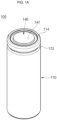
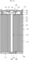
- FIGS. 1A and 1B are a perspective view and a cross-sectional view of a cylindrical lithium ion secondary battery 100 according to various embodiments of the present invention
- FIG. 1C is an exploded perspective view illustrating only a cap assembly 140.
- the cylindrical lithium ion secondary battery 100 may include a cylindrical can 110, an electrode assembly 120 and a cap assembly 140.
- the cylindrical lithium ion secondary battery 100 may further include a center pin 130.
- the cap assembly 140 performs a current blocking operation, and thus may be referred to as a current interrupt device in some cases.
- the cylindrical can 110 includes a circular bottom portion 111 and a side wall 112 upwardly extending a predetermined length from the periphery of the bottom portion 111. In the process of manufacturing the secondary battery, a top portion or top end of the cylindrical can 110 is left open. Therefore, in the process of assembling the secondary battery 100, the electrode assembly 120 and the center pin 130 may be inserted into the cylindrical can 110 together with an electrolyte.
- the cylindrical can 110 may be made of, for example, steel, a steel alloy, aluminum, an aluminum alloy, or an equivalent thereof, but embodiments of the present invention are not limited thereto.
- cylindrical can 110 may include an inwardly recessed beading part 113 formed below the cap assembly 140 so as to prevent the electrode assembly 120 from being separated from the cap assembly 140 and an inwardly bent crimping part 114 formed on or above the beading part 113.
- the electrode assembly 120 is received in the cylindrical can 110.
- the electrode assembly 120 includes a negative electrode plate 121 coated with a negative electrode active material (e.g., graphite or carbon), a positive electrode plate 122 coated with a positive electrode active material (e.g., a transition metal oxide, such as LiCoO 2 , LiNiO 2 , or LiMn 2 O 4 ), and a separator 123 interposed between the negative electrode plate 121 and the positive electrode plate 122 to prevent a short circuit between the negative electrode plate 121 and the positive electrode plate 122 while allowing only movement of lithium ions.
- the negative electrode plate 121, the positive electrode plate 122, and the separator 123 are wound in a substantially cylindrical shape or configuration.
- the negative electrode plate 121 may be formed of a copper (Cu) or nickel (Ni) foil
- the positive electrode plate 122 may be formed of an aluminum (Al) foil
- the separator 123 may be made of polyethylene (PE) or polypropylene (PP), but embodiments of the present invention are not limited thereto.
- a negative electrode tab 124 may be welded to the negative electrode plate 121 to downwardly protrude and extend a predetermined length therefrom, and a positive electrode tab 125 may be welded to the positive electrode plate 122 to upwardly protrude and extend a predetermined length therefrom, or vice versa.
- the negative electrode tab 124 may be made of copper or nickel, and the positive electrode tab 125 may be made of aluminum, but embodiments of the present invention are not limited thereto.
- the negative electrode tab 124 of the electrode assembly 120 may be welded to the bottom portion 111 of the cylindrical can 110. Therefore, the cylindrical can 110 may function as a negative electrode.
- the positive electrode tab 125 may be welded to the bottom portion 111 of the cylindrical can 110. In these embodiments, the cylindrical can 110 may function as a positive electrode.
- a first insulating plate 126 which is coupled to the cylindrical can 110 and has a first hole 126a formed at its center and a second hole 126b formed around the first hole 126a, may be interposed between the electrode assembly 120 and the bottom portion 111 of the cylindrical can 110.
- the first insulating plate 126 may prevent the electrode assembly 120 from electrically contacting the bottom portion 111 of the cylindrical can 110.
- the first insulating plate 126 prevents the positive electrode plate 122 of the electrode assembly 120 from electrically contacting the bottom portion 111.
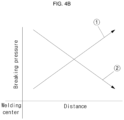
- FIGS. 4A and 4B are a cross-sectional view and a graph illustrating the relationship between rupture pressures/operating pressures and welding regions of the cap assembly 140 in the cylindrical lithium ion secondary battery 100 according to various embodiments of the present invention.
- the X-axis indicates the distance of a welding region from the center
- the Y-axis indicates the rupture pressure/operating pressure.
- the breaking pressure of a top plate is gradually increased away from the center of welding regions of the top plate toward the periphery of the top plate.
- the pressure required for operating or breaking the top plate is increased.
- the pressure required for operating or breaking the top plate is decreased.
- the breaking pressure of the top plate is gradually decreased away from the center of welding regions of the top plate toward the center of the top plate. In other words, as the welding region is formed to be closer to the center of the top plate, the pressure required for operating or breaking the top plate is decreased. In still other words, as the welding region is formed to be closer to the periphery of the top plate, the pressure required for operating or breaking the top plate is increased.
Landscapes
- Chemical & Material Sciences (AREA)
- Chemical Kinetics & Catalysis (AREA)
- Electrochemistry (AREA)
- General Chemical & Material Sciences (AREA)
- Engineering & Computer Science (AREA)
- Manufacturing & Machinery (AREA)
- Materials Engineering (AREA)
- Gas Exhaust Devices For Batteries (AREA)
- Sealing Battery Cases Or Jackets (AREA)
- Secondary Cells (AREA)
Description
- Various embodiments of the present invention relate to a cylindrical lithium ion secondary battery.
- Lithium ion secondary batteries are being widely used in portable electronic devices and power sources of hybrid automobiles or electric vehicles because of various advantages, including a high operation voltage, a high energy density per unit weight, and so forth.
- The lithium ion secondary battery can be largely classified as a cylinder type secondary battery, a prismatic type secondary battery, a pouch type secondary battery. Specifically, the cylindrical lithium ion secondary battery generally includes a cylindrical electrode assembly, a cylindrical can coupled to the electrode assembly, an electrolyte injected into the can to allow movement of lithium ions, and a cap assembly coupled to one side of the can to prevent leakage of the electrolyte and separation of the electrode assembly.
-
EP 2224511 A1 relates to a rechargeable battery. -
US 2016/087318 A1 relates to a rechargeable battery which has a heat-resistant insulating layer. -
US 2017/133645 A1 relates to a cylindrical sealed battery and a battery pack including such a battery. - Various embodiments of the present invention provide a cylindrical lithium ion secondary battery which, when an internal gas pressure is larger than a predetermined first reference pressure (operating pressure) and is smaller than a predetermined second reference pressure (breaking pressure) during overcharging, can maintain an internal sealing while a current path is blocked by a cap assembly.
- Various embodiments of the present invention provide a cylindrical lithium ion secondary battery which can rapidly release the internal gas without any obstructions by allowing the cap assembly to be broken or ruptured (opened) when an internal gas pressure is larger than a predetermined second reference pressure (breaking pressure).
- Various embodiments of the present invention provide a cylindrical lithium ion secondary battery which can arbitrarily determine the breaking pressure of the cap assembly according to the location of a welding region formed.
- According to various embodiments of the present invention, provided is a cylindrical lithium ion secondary battery comprising: a cylindrical can; an electrode assembly received in the cylindrical can; and a cap assembly for sealing the cylindrical can, wherein the cap assembly comprises a top plate having a flat surface on which a notch is formed, a middle plate coupled to the top plate and including a first through-hole formed through the center thereof, and a bottom plate electrically connected with the electrode assembly, attached to the middle plate with an insulating plate interposed therebetween, and connected to the top plate through the first through-hole of the middle plate.
- The top plate may include a flat top surface and a flat bottom surface opposite to the top surface, and the notch is formed on the bottom surface.
- The top plate may include a flat upper region positioned on the middle plate, a side region downwardly bent from the upper region and positioned at a side portion of the middle plate, and a lower region bent from the side region and positioned at a bottom portion of the middle plate.
- The notch may be formed at an exterior side of a region corresponding to the first through-hole of the middle plate.
- The middle plate may further include a plurality of second through-holes formed around the first through-hole.
- When the internal gas pressure of the cylindrical can is larger than a predetermined first pressure and smaller than a predetermined second pressure, the top plate may be upwardly convexly deformed by the internal gas pressure, and the top plate may be electrically disconnected from the bottom plate.
- When the internal gas pressure of the cylindrical can is larger than the predetermined second pressure, the notch may be broken, and the internal gas of the cylindrical can may then be released to the outside.
- To determine the breaking pressure of the top plate, one or more welding regions may further be formed between the top plate and the middle plate.
- As the welding regions formed are located far away from the edge of the top plate, the breaking pressure of the top plate may be relatively small.
- As described above, in the cylindrical lithium ion secondary battery according to various embodiments, when an internal gas pressure is larger than a predetermined first reference pressure (operating pressure) and is smaller than a predetermined second reference pressure (breaking pressure), an internal sealing can be maintained while a current path is blocked by a cap assembly.
- In the cylindrical lithium ion secondary battery according to various embodiments, the internal gas can be released to the outside without any obstructions by allowing the cap assembly to be broken or ruptured (opened) when the internal gas pressure, after a current path is blocked by the cap assembly, is larger than a predetermined second reference pressure (breaking pressure).
- In the cylindrical lithium ion secondary battery according to various embodiments, the breaking pressure of the cap assembly can be arbitrarily determined according to the location of a welding region formed.
- In the cylindrical lithium ion secondary battery according to various embodiments, a relatively large battery capacity can be achieved by making an upper end height of the cap assembly equal to or smaller than that of a cylindrical can.
- The cylindrical lithium ion secondary battery according to various embodiments includes a cap assembly including relatively soft pure aluminum or an aluminum alloy, so that the cap assembly is easily broken (opened) when the internal gas pressure reaches a predetermined reference pressure, thereby improving the safety of battery.
-
-
FIGS. 1A and1B are a perspective view and a cross-sectional view of a secondary battery according to various embodiments of the present invention, andFIG. 1C is an exploded perspective view illustrating only a cap assembly. -
FIGS. 2A and2B are cross-sectional views illustrating states in which the cap assembly operates and ruptures in the cylindrical secondary battery according to an embodiment of the present invention. -
FIGS. 3A and3B are cross-sectional views illustrating cap assemblies of the secondary battery according to various embodiments of the present invention. -
FIGS. 4A and4B are a cross-sectional view and a graph illustrating the relationship between breaking pressures/operating pressures and welding regions of the cap assembly in the cylindrical secondary battery according to various embodiments of the present invention. - Hereinafter, embodiments of the present invention will be described in detail.
- The embodiments of the present invention, however, may be modified in many different forms and should not be construed as being limited to the example (or exemplary) embodiments set forth herein. Rather, these example embodiments are provided so that this invention will be thorough and complete and will convey the aspects and features of the present invention to those skilled in the art.
- In addition, in the accompanying drawings, sizes or thicknesses of various components are exaggerated for brevity and clarity. Like numbers refer to like elements throughout. As used herein, the term "and/or" includes any and all combinations of one or more of the associated listed items. In addition, it will be understood that when an element A is referred to as being "connected to" an element B, the element A can be directly connected to the element B or an intervening element C may be present therebetween such that the element A and the element B are indirectly connected to each other.
- The terminology used herein is for the purpose of describing particular embodiments only and is not intended to be limiting of the invention. As used herein, the singular forms are intended to include the plural forms as well, unless the context clearly indicates otherwise. It will be further understood that the terms that the terms "comprise or include" and/or "comprising or including," when used in this specification, specify the presence of stated features, numbers, steps, operations, elements, and/or components, but do not preclude the presence or addition of one or more other features, numbers, steps, operations, elements, components, and/or groups thereof.
- It will be understood that, although the terms first, second, etc. may be used herein to describe various members, elements, regions, layers and/or sections, these members, elements, regions, layers and/or sections should not be limited by these terms. These terms are only used to distinguish one member, element, region, layer and/or section from another. Thus, for example, a first member, a first element, a first region, a first layer and/or a first section discussed below could be termed a second member, a second element, a second region, a second layer and/or a second section without departing from the teachings of the present invention.
- Spatially relative terms, such as "beneath," "below," "lower," "above," "upper," and the like, may be used herein for ease of description to describe one element or feature's relationship to another element(s) or feature(s) as illustrated in the figures. It will be understood that the spatially relative terms are intended to encompass different orientations of the device in use or operation in addition to the orientation depicted in the figures. For example, if the element or feature in the figures is turned over, elements described as "below" or "beneath" other elements or features would then be oriented "on" or "above" the other elements or features. Thus, the exemplary term "below" can encompass both an orientation of above and below.
-
FIGS. 1A and1B are a perspective view and a cross-sectional view of a cylindrical lithium ionsecondary battery 100 according to various embodiments of the present invention, andFIG. 1C is an exploded perspective view illustrating only acap assembly 140. - As illustrated in
FIGS. 1A ,1B and1C , the cylindrical lithium ionsecondary battery 100 according to various embodiments may include acylindrical can 110, anelectrode assembly 120 and acap assembly 140. In some cases, the cylindrical lithium ionsecondary battery 100 may further include acenter pin 130. In addition, in the cylindrical lithium ionsecondary battery 100 according to various embodiments, thecap assembly 140 performs a current blocking operation, and thus may be referred to as a current interrupt device in some cases. - The
cylindrical can 110 includes acircular bottom portion 111 and aside wall 112 upwardly extending a predetermined length from the periphery of thebottom portion 111. In the process of manufacturing the secondary battery, a top portion or top end of thecylindrical can 110 is left open. Therefore, in the process of assembling thesecondary battery 100, theelectrode assembly 120 and thecenter pin 130 may be inserted into the cylindrical can 110 together with an electrolyte. The cylindrical can 110 may be made of, for example, steel, a steel alloy, aluminum, an aluminum alloy, or an equivalent thereof, but embodiments of the present invention are not limited thereto. - In addition, the cylindrical can 110 may include an inwardly recessed
beading part 113 formed below thecap assembly 140 so as to prevent theelectrode assembly 120 from being separated from thecap assembly 140 and an inwardly bent crimpingpart 114 formed on or above thebeading part 113. - The
electrode assembly 120 is received in thecylindrical can 110. Theelectrode assembly 120 includes anegative electrode plate 121 coated with a negative electrode active material (e.g., graphite or carbon), apositive electrode plate 122 coated with a positive electrode active material (e.g., a transition metal oxide, such as LiCoO2, LiNiO2, or LiMn2O4), and aseparator 123 interposed between thenegative electrode plate 121 and thepositive electrode plate 122 to prevent a short circuit between thenegative electrode plate 121 and thepositive electrode plate 122 while allowing only movement of lithium ions. Thenegative electrode plate 121, thepositive electrode plate 122, and theseparator 123 are wound in a substantially cylindrical shape or configuration. Here, thenegative electrode plate 121 may be formed of a copper (Cu) or nickel (Ni) foil, thepositive electrode plate 122 may be formed of an aluminum (Al) foil, and theseparator 123 may be made of polyethylene (PE) or polypropylene (PP), but embodiments of the present invention are not limited thereto. - In addition, a
negative electrode tab 124 may be welded to thenegative electrode plate 121 to downwardly protrude and extend a predetermined length therefrom, and apositive electrode tab 125 may be welded to thepositive electrode plate 122 to upwardly protrude and extend a predetermined length therefrom, or vice versa. In addition, thenegative electrode tab 124 may be made of copper or nickel, and thepositive electrode tab 125 may be made of aluminum, but embodiments of the present invention are not limited thereto. - In addition, the
negative electrode tab 124 of theelectrode assembly 120 may be welded to thebottom portion 111 of thecylindrical can 110. Therefore, the cylindrical can 110 may function as a negative electrode. In other embodiments, thepositive electrode tab 125 may be welded to thebottom portion 111 of thecylindrical can 110. In these embodiments, the cylindrical can 110 may function as a positive electrode. - Additionally, a first insulating
plate 126, which is coupled to thecylindrical can 110 and has afirst hole 126a formed at its center and asecond hole 126b formed around thefirst hole 126a, may be interposed between theelectrode assembly 120 and thebottom portion 111 of thecylindrical can 110. The first insulatingplate 126 may prevent theelectrode assembly 120 from electrically contacting thebottom portion 111 of thecylindrical can 110. Specifically, the first insulatingplate 126 prevents thepositive electrode plate 122 of theelectrode assembly 120 from electrically contacting thebottom portion 111. Here, when a relatively large amount of gas is generated due to an abnormality in the secondary battery, thefirst hole 126a allows the gas to rapidly move upwardly through thecenter pin 130, and thesecond hole 126b allows thenegative electrode tab 124 to pass therethrough to be welded to thebottom portion 111. - In addition, a second insulating
plate 127, which is coupled to thecylindrical can 110 and has afirst hole 127a formed at its center and a plurality ofsecond holes 127b formed around thefirst hole 127a, may be interposed between theelectrode assembly 120 and thebottom portion 111 of thecylindrical can 110. The second insulatingplate 127 may prevent theelectrode assembly 120 from electrically contacting thebottom portion 111 of thecylindrical can 110. Specifically, the second insulatingplate 127 prevents thenegative electrode plate 121 of theelectrode assembly 120 from electrically contacting thecap assembly 140. Here, when a relatively large amount of gas is generated due to an abnormality in the secondary battery, thefirst hole 127a allows the gas to rapidly move to thecap assembly 140, and thesecond hole 127b allows thepositive electrode tab 125 to pass therethrough to be welded to thecap assembly 140. In addition, during injection of an electrolyte, the othersecond hole 127b allows the electrolyte to rapidly flow into theelectrode assembly 120. - In addition, since diameters of the
first holes plates center pin 130, it is possible to prevent thecenter pin 130 from electrically contacting thebottom portion 111 of the cylindrical can 110 or thecap assembly 140 due to an external shock. - The
center pin 130 is shaped of a hollow cylindrical pipe and is coupled to a substantially central portion of theelectrode assembly 120. Thecenter pin 130 may be made of steel, stainless steel, aluminum, an aluminum alloy, or polybutylene terephthalate, but embodiments of the present invention are not limited to the above materials. Thecenter pin 130 prevents theelectrode assembly 120 from being deformed during charging or discharging of the secondary battery, and may serve as a gas movement path. Of course, in some embodiments, thecenter pin 130 may not be provided. - The
cap assembly 140 may include atop plate 141, amiddle plate 142, an insulatingplate 143 and abottom plate 144. - The
top plate 141 includes a substantially flattop surface 141a and a substantially flatbottom surface 141b opposite to thetop surface 141 a. Particularly, thetop plate 141 may further at least onenotch 141c formed on thebottom surface 141b. Here, thenotch 141c may have a substantially inverted V ("Λ") shaped cross section. In addition, when viewed from below, thenotch 141c may have, for example, a substantially circular, elliptical or "C" shape, but embodiments of the present invention are not limited to the above shapes. Thenotch 141c is broken or ruptured when the internal gas pressure of the secondary battery is larger than a predetermined reference pressure, thereby rapidly releasing the internal gas of the battery to the outside and ultimately securing the safety of battery. - In addition, the
top plate 141 may include anupper region 141d, aside region 141e, and alower region 141f. Theupper region 141d may be positioned on themiddle plate 142 and may be substantially flat. Theupper region 141d may serve as a terminal of the secondary battery, and thus may be electrically connected to an external device (e.g., a load or a charger). Theside region 141e may be downwardly bent from theupper region 141d to substantially encompass a side portion of themiddle plate 142. Thelower region 141f is horizontally inwardly bent from theside region 141e to then be positioned at a bottom portion of themiddle plate 142. In such a manner, thetop plate 141 may be combined with themiddle plate 142 by theupper region 141d, theside region 141e, and thelower region 141f. - Additionally, a height of the
upper region 141d of thetop plate 141 may be made to be equal to or smaller than that of the crimpingpart 114 of thecylindrical can 110, which increases the internal volume of thecylindrical can 110, thereby increasing the capacity of the secondary battery. Here, the height means a height ranging from thebottom portion 111 of thecylindrical can 110. - The
top plate 141 may be made of, for example, aluminum, aluminum, an aluminum alloy or equivalents thereof, but embodiments of the present invention are not limited to the above materials. Accordingly, a bus bar, an external lead or an external device, made of aluminum, may be easily connected (or welded) to thetop plate 141. - Here, the
top plate 141 may be made of one selected from the group consisting of 1XXX series alloys, that is, pure aluminum of 99.0% or greater purity, 2XXX series alloys, that is, Al-Cu alloys, 3XXX series alloys, that is, Al-Mn alloys, 4XXX series alloys, that is, Al-Si alloys, 5XXX series alloys, that is, Al-Mg alloys, 6XXX series alloys, that is, Al-Mg-Si alloys, and 7XXX series alloys, that is, Al-Zn-(Mg, Cu) alloys. - Specifically, the
top plate 141 is preferably made of soft aluminum among the above-mentioned series alloys. For example, thetop plate 141 may be made of, but not limited to, a 5XXX series (e.g., 5052, 5056, 5083, or 5454) Al-Mg alloy having a high strength, excellent corrosion resistance and good weldability. Additionally, a 1XXX, 3XXX or 4XXX series alloy, which is a non-heat treatable alloy, may be used as a material of thetop plate 141. - In some cases, the
top plate 141 may further include abent region 141g formed on theupper region 141d. When viewed from below, thebent region 141g may be shaped of a substantially circular ring. As an example, theupper region 141d located inside thebent region 141g may be positioned higher than theupper region 141d located outside thebent region 141g. In addition, thenotch 141c may be formed on theupper region 141d located inside thebent region 141g. - The
middle plate 142 may be positioned under thetop plate 141 and may be substantially flat. In addition, themiddle plate 142 may include a first through-hole 142a formed at a roughly central portion. Moreover, themiddle plate 142 may include a plurality of second through-holes 142b formed around the first through-hole 142a. - Here, a
bottom plate 144, which will later be described, may pass through the first through-hole 142a to then be electrically connected to thetop plate 141, and may allow the internal gas pressure to be directly applied to thetop plate 141. In addition, the second through-holes 142b may also allow the internal gas pressure to be directly applied to thetop plate 141. - The
notch 141c formed on thebottom surface 141b of thetop plate 141 may be located to correspond to, for example, a region between the first through-hole 142a and each of the second through-holes 142b of themiddle plate 142. - Additionally, the
middle plate 142 may also include abent region 142c formed on a region corresponding to thebent region 141g of thetop plate 141. In addition, the second through-holes 142b may be formed in thebent region 142c. Therefore, themiddle plate 142 may be generally configured such that it makes a close contact with thebottom surface 141b of thetop plate 141. - The
middle plate 142 may be made of, for example, aluminum, aluminum, an aluminum alloy or equivalents thereof, but embodiments of the present invention are not limited thereto. - The insulating
plate 143 may be positioned under (attached to a bottom portion of) themiddle plate 142 and may include a through-hole 143a located to correspond to the first through-hole 142a. When viewed from below, the insulatingplate 143 may be shaped of a substantially circular ring having a predetermined width. As an example, the insulatingplate 143 may be located to correspond to a region between the first through-hole 142a and each of the second through-holes 142b of themiddle plate 142. In addition, the insulatingplate 143 serves to insulate themiddle plate 142 and thebottom plate 144 from each other. For example, the insulatingplate 143 may be positioned between themiddle plate 142 and thebottom plate 144 and may be subjected to ultrasonic welding, but embodiments of the present invention are not limited thereto. - The insulating
plate 143 may be made of, for example, polyethylene (PE), polypropylene (PP), ethylene propylene diene monomer (M-class) rubber (EPDM rubber), or equivalents thereof, but embodiments of the present invention are not limited to the above materials. These insulating materials do not react with an electrolyte, and thus the insulatingplate 143 may not be deformed even after the long-period use of thesecondary battery 100. - The
bottom plate 144 is electrically connected to thetop plate 141 through the through-hole 143a of the insulatingplate 143 and the first through-hole 142a of themiddle plate 142 to then be attached to the insulatingplate 143. That is to say, thebottom plate 144 may include afirst area 144a connected (welded) to theupper region 141d of thetop plate 141, asecond area 144b bent from thefirst area 144a and passing through the through-hole 142a of themiddle plate 142 and the through-hole 143a of the insulatingplate 143, and athird area 144c substantially outwardly bent from thesecond area 144b and attached to the insulatingplate 143. InFIG. 1C , undefined reference numeral 144e refers to a welding region in which thefirst area 144a of thebottom plate 144 is welded to thebottom surface 141b of theupper region 141d of thetop plate 141. - Here, the
positive electrode tab 125 may be electrically connected to thethird area 144c of thebottom plate 144. In addition, thethird area 144c is spaced apart from themiddle plate 143 and is also spaced apart from thethird region 141f of thetop plate 141. In addition, thefirst area 144a of thebottom plate 144 may further include one or more concavely recessedgrooves 144d. When the internal gas pressure of the battery is larger than a predetermined pressure, thetop plate 141 is upwardly convexly deformed. In this case, thegrooves 144d may serve to make thefirst area 144a of thebottom plate 144 easily separated from thesecond area 144b. Consequently, a current path between thetop plate 141 and thebottom plate 144 may be blocked. - The
bottom plate 144 may be made of, for example, aluminum, aluminum, an aluminum alloy or equivalents thereof, and thus thepositive electrode tab 125 made of aluminum may be easily welded thereto. - The
cap assembly 140 may further include an insulatinggasket 145 insulating thetop plate 141 and thesidewall 111 of the cylindrical can 110 from each other. Here, the insulatinggasket 145 is configured to be substantially compressed between thebeading part 113 and the crimpingpart 114 formed on thesidewall 111 of thecylindrical can 110. In addition, the insulatinggasket 145 may substantially encompass theside region 141e of thetop plate 141, and thetop region 141d and thelower region 141g located therearound, thereby sealing the interior of the battery. - Additionally, an electrolyte (not shown) is injected into the
cylindrical can 110, and lithium ions generated by an electrochemical reaction in thenegative electrode plate 121 and thepositive electrode plate 122 in the secondary battery during charging and discharging are allowed to move. The electrolyte may be a non-aqueous, organic electrolyte including a mixture of a lithium salt and a high-purity organic solvent. In addition, the electrolyte may be a polymer using a polymer electrolyte or a solid electrolyte. However, embodiments of the present invention are not limited to the above electrolytes. - With such features of the
cap assembly 140, the cylindrical lithium ionsecondary battery 100 according to the embodiment may have a relatively large capacity by making the upper end height of thecap assembly 140 equal to or smaller than that of thecylindrical can 110. In addition, the cylindrical lithium ionsecondary battery 100 includes thecap assembly 140 including relatively soft pure aluminum or an aluminum alloy, so that thecap assembly 140 is easily broken or ruptured (opened) when the internal gas pressure reaches a predetermined reference pressure, thereby improving the safety of battery. -
FIGS. 2A and2B are cross-sectional views illustrating states in which thecap assembly 140 operates and ruptures in the cylindrical lithium ionsecondary battery 100 according to an embodiment of the present invention. - As illustrated in
FIG. 2A , in the cylindrical lithium ionsecondary battery 100 according to various embodiments, when the internal gas pressure of thecylindrical can 110 is larger than a predetermined first reference pressure (operating pressure) and is smaller than a predetermined second reference pressure (breaking pressure), thetop plate 141 is upwardly convexly deformed (inverted), and thetop plate 141 may be electrically disconnected from thebottom plate 144. That is to say, thefirst area 144a of thebottom plate 144 is broken to then be separated from thesecond area 144b. In other words, thegrooves 144d of thefirst area 144a are ruptured, and some regions of thefirst area 144a upwardly move in a state in which they are still connected to thetop plate 141. Consequently, a current path between thetop plate 141 and thebottom plate 144 may be blocked. - However, when the internal gas pressure of the secondary battery is smaller than the predetermined second reference pressure (breaking pressure), a sealing of the secondary battery may be maintained, thereby preventing the internal gas from being released to the outside.
- When the battery is overcharged, when an internal short-circuit occurs to the cylindrical secondary battery due to penetration and/or collapse, or when an external short-circuit occurs to the battery, internal gas may be generated due to decomposition of an electrolyte and/or decomposition of an active material, resulting in an increase in the internal gas pressure of the secondary battery. Here, the secondary battery is designed such that the second reference pressure (breaking pressure) is larger than the first reference pressure (operating pressure). Such an increase in the internal gas pressure of the secondary battery may suggest that the secondary battery is at an abnormal state, and thus the current path is first blocked by the above-mentioned mechanical mechanism (charge current, discharge current, short-circuit current, or overcurrent), thereby improving the safety of the secondary battery.
- As illustrated in
FIG. 2B , in the cylindrical lithium ionsecondary battery 100 according to various embodiments, when the internal gas pressure of thecylindrical can 110 is larger than the predetermined second pressure (breaking pressure), thetop plate 141 is ruptured to thus rapidly release the internal gas without any obstructions. That is to say, as thenotch 141c formed on thebottom surface 141b of thetop plate 141 is ruptured, the gas existing within thesecondary battery 100 is rapidly released to the outside, thereby preventing explosion of thesecondary battery 100 and ultimately increasing the safety of thesecondary battery 100. From the viewpoint of safety, releasing the internal gas to the outside in advance is more advantageous than letting thesecondary battery 100 explode under a high pressure as described above. - In addition, the breaking pressure (or the second pressure) of the
top plate 141 may be adjusted by the depth of thenotch 141c formed. For example, the breaking pressure may be increased by forming thenotch 141c so as to have a relatively small depth, and the breaking pressure may be reduced by forming thenotch 141c so as to have a relatively large depth. - As described above, when the internal gas pressure is larger than the predetermined first reference pressure (operating pressure) and is smaller than the predetermined second reference pressure (breaking pressure), the cylindrical lithium ion
secondary battery 100 according to the embodiments may primarily block the current path by thecap assembly 140. Here, the internal sealing of the battery is still maintained. In addition, when the internal gas pressure, after the current path is blocked by thecap assembly 140, is larger than the predetermined second reference pressure (breaking pressure), thecap assembly 140 is broken or ruptured (opened), and thus the cylindrical lithium ionsecondary battery 100 according to the embodiments may secondly release the internal gas to the outside without any obstructions. - That is to say, the cylindrical lithium ion
secondary battery 100 according to the embodiments may perform a safety-related operation in two steps by primarily blocking the current path when the internal gas pressure is larger than the predetermined first reference pressure, and secondly releasing the internal gas to the outside when the internal gas pressure is larger than the predetermined second reference pressure. - Meanwhile, the breaking pressure of the
top plate 141 may be determined by a hinge point formed during operation (inversion) of thetop plate 141 as well as by the depth of thenotch 141c. That is to say, when thetop plate 141 is inverted, there may be a hinge point at which the inversion is initiated. For example, the hinge point may be a boundary region between the insulatinggasket 145 and thetop plate 141. That is to say, the hinge point may be a region of theupper region 141d of thetop plate 141, which corresponds to an end of the insulatinggasket 145. Therefore, the breaking pressure of thetop plate 141 may vary according to the location of the hinge point, which will be described below. -
FIGS. 3A and3B are cross-sectional views illustratingcap assemblies secondary battery 100 according to various embodiments of the present invention. - As illustrated in
FIGS. 3A and3B , in the cylindrical lithium ionsecondary battery 100 according to various embodiments, in order to determine (adjust) the breaking pressure of thetop plate 141, thecap assemblies more welding regions top plate 141 and themiddle plate 142, respectively. Thewelding regions welding regions welding regions top plate 141 and themiddle plate 142, for example, but embodiments of the present invention are not limited thereto. That is to say, thewelding regions top plate 141 and themiddle plate 142, which correspond to a location between each of the second through-holes 142b of themiddle plate 142 and the periphery of themiddle plate 142, but embodiments of the present invention are not limited thereto. - Here, the breaking pressure of the
top plate 141 may be gradually decreased as thewelding regions top plate 141. In other words, the breaking pressure of thetop plate 141 may be gradually increased as thewelding regions top plate 141. Here, the breaking pressure means a pressure at which thenotch 141c formed in thetop plate 141 is broken or ruptured. - As an example, as illustrated in
FIG. 3A , when thewelding region 146A is located relatively far from the edge of the top plate 141 (that is, when thewelding region 146A is located relatively close to the center of the top plate 141), the breaking pressure of thetop plate 141 may be relatively small. That is to say, thenotch 141c of thetop plate 141 may be broken or ruptured by a relatively small internal pressure of the battery. - As another example, as illustrated in
FIG. 3B , when thewelding region 146B is located relatively close to the edge of the top plate 141 (that is, when thewelding region 146B is located relatively far from the center of the top plate 141), the breaking pressure of thetop plate 141 may be relatively large. That is to say, thenotch 141c of thetop plate 141 may be broken or ruptured by a relatively large internal pressure of the battery. - Such a change in the breaking pressure is attributable to a volumetric change for breaking.
- In other words, the
welding regions upper region 141d of thetop plate 141 may be considered to be an inverted region. - As the
welding regions top plate 141 may be increased, and thus a relatively large internal pressure may be required for operating or breaking thetop plate 141. Accordingly, the breaking pressure/operating pressure may be increased. - However, as the
welding regions top plate 141 may be decreased, and thus a relatively small internal pressure may be required for operating or breaking thetop plate 141. Accordingly, the breaking pressure/operating pressure may be reduced. - That is, according to the present invention, the
welding regions gasket 145 and thetop plate 141, are arbitrarily determined as the hinge points of thetop plate 141, thereby allowing thesecondary battery 100 to arbitrarily adjust the operating pressure and/or the breaking pressure of thetop plate 141. - In addition, the operating pressure and/or the breaking pressure of the
top plate 141 in any type of secondary battery may be uniformly controlled by adjusting the operating pressure and/or the breaking pressure of thetop plate 141 using thewelding regions - Practically, the breaking pressure and the operating pressure may be increased or decreased together.
-
FIGS. 4A and4B are a cross-sectional view and a graph illustrating the relationship between rupture pressures/operating pressures and welding regions of thecap assembly 140 in the cylindrical lithium ionsecondary battery 100 according to various embodiments of the present invention. InFIG. 4B , the X-axis indicates the distance of a welding region from the center, and the Y-axis indicates the rupture pressure/operating pressure. - As illustrated in
FIGS. 4A and4B , the breaking pressure of a top plate is gradually increased away from the center of welding regions of the top plate toward the periphery of the top plate. In other words, as a welding region is formed to be closer to the periphery of the top plate, the pressure required for operating or breaking the top plate is increased. In still other words, as a welding region is formed to be closer to the center of the top plate, the pressure required for operating or breaking the top plate is decreased. - In addition, as illustrated in
FIGS. 4A and4B , the breaking pressure of the top plate is gradually decreased away from the center of welding regions of the top plate toward the center of the top plate. In other words, as the welding region is formed to be closer to the center of the top plate, the pressure required for operating or breaking the top plate is decreased. In still other words, as the welding region is formed to be closer to the periphery of the top plate, the pressure required for operating or breaking the top plate is increased. - Although the foregoing embodiments have been described to practice the cylindrical lithium ion secondary battery of the present invention, these embodiments are set forth for illustrative purposes and do not serve to limit the invention. Those skilled in the art will readily appreciate that many modifications and variations can be made, without departing from the scope of the invention as defined in the appended claims, and such modifications and variations are encompassed within the scope of the present invention.
Claims (8)
- A cylindrical lithium ion secondary battery (100) comprising:a cylindrical can (110); an electrode assembly (120) received in the cylindrical can (110); anda cap assembly (140) for sealing the cylindrical can (110),wherein the cap assembly (140) comprises a top plate (141) having a flat surface on which a notch (141c) is formed, a middle plate (142) coupled to the top plate (141) and including a first through-hole (142a) formed through the center thereof, and a bottom plate (144) electrically connected with the electrode assembly (120), attached to the middle plate (142) with an insulating plate (143) interposed therebetween, and connected to the top plate (141) through the first through-hole (142a) of the middle plate (142).
- The cylindrical lithium ion secondary battery (100) of claim 1, wherein the top plate (141) includes a flat top surface (141a) and a flat bottom surface (141b) opposite to the top surface (141a), and the notch (141c) is formed on the bottom surface (141b).
- The cylindrical lithium ion secondary battery (100) of claim 1, wherein the top plate (141) includes a flat upper region (141d) positioned on the middle plate (142), a side region (141e) downwardly bent from the upper region (141d) and positioned at a side portion of the middle plate (142), and a lower region (141f) bent from the side region (141e) and positioned at a bottom portion of the middle plate (142).
- The cylindrical lithium ion secondary battery (100) of claim 1, wherein the notch (141c) is formed at an exterior side of a region corresponding to the first through-hole (142a) of the middle plate (142).
- The cylindrical lithium ion secondary battery (100) of claim 1, wherein the middle plate (142) further includes a plurality of second through-holes (142b) formed around the first through-hole (142a).
- The cylindrical lithium ion secondary battery (100) of claim 1, wherein the bottom plate (144) includes a first area (144a) connected to an upper region (141d) of the top plate (141), a second area (144b) bent from the first area (144a) and passing through the first through-hole (142a) of the middle plate (142) and a third area (144c) outwardly bent from the second area (144b) and attached to the insulating plate (143), the first area (144a) of the bottom plate (144) includes one or more grooves (144d), the one or more grooves (144d) are configured such that the first area (144a) of the bottom plate (144) is separated from the second area (144b) when the internal gas pressure of the cylindrical can (110) is larger than a predetermined first pressure and smaller than a predetermined second pressure and the top plate (141) is upwardly convexly deformed by the internal gas pressure, and as a result the top plate (140) is electrically disconnected from the bottom plate (144).
- The cylindrical lithium ion secondary battery (100) of claim 6, wherein, the notch (141c) is configured to rupture when the internal gas pressure of the cylindrical can (110) is larger than the predetermined second pressure, and the internal gas of the cylindrical can (110) is then released to the outside.
- The cylindrical lithium ion secondary battery (100) of claim 1, wherein one or more welding regions (146A, 146B) are further formed between the top plate (140) and the middle plate (142).
Priority Applications (1)
| Application Number | Priority Date | Filing Date | Title |
|---|---|---|---|
| HUE17934863A HUE070610T2 (en) | 2017-12-13 | 2017-12-13 | Cylindrical lithium ion secondary battery |
Applications Claiming Priority (1)
| Application Number | Priority Date | Filing Date | Title |
|---|---|---|---|
| PCT/KR2017/014616 WO2019117343A1 (en) | 2017-12-13 | 2017-12-13 | Cylindrical lithium ion secondary battery |
Publications (3)
| Publication Number | Publication Date |
|---|---|
| EP3726617A1 EP3726617A1 (en) | 2020-10-21 |
| EP3726617A4 EP3726617A4 (en) | 2021-07-28 |
| EP3726617B1 true EP3726617B1 (en) | 2025-01-08 |
Family
ID=66819542
Family Applications (1)
| Application Number | Title | Priority Date | Filing Date |
|---|---|---|---|
| EP17934863.6A Active EP3726617B1 (en) | 2017-12-13 | 2017-12-13 | Cylindrical lithium ion secondary battery |
Country Status (7)
| Country | Link |
|---|---|
| US (1) | US20210184308A1 (en) |
| EP (1) | EP3726617B1 (en) |
| KR (1) | KR102461576B1 (en) |
| CN (1) | CN111566840B (en) |
| HU (1) | HUE070610T2 (en) |
| PL (1) | PL3726617T3 (en) |
| WO (1) | WO2019117343A1 (en) |
Families Citing this family (7)
| Publication number | Priority date | Publication date | Assignee | Title |
|---|---|---|---|---|
| KR102852652B1 (en) | 2020-09-16 | 2025-08-29 | 주식회사 엘지에너지솔루션 | Manufacturing method for secondary battery and secondary battery manufactured by the same |
| US20240234931A9 (en) * | 2021-02-19 | 2024-07-11 | Lg Energy Solution, Ltd. | Battery, and battery pack and vehicle including the same |
| DE102021119259A1 (en) | 2021-07-26 | 2023-01-26 | Bayerische Motoren Werke Aktiengesellschaft | Energy storage cell and method for producing an energy storage cell |
| CN115863869B (en) * | 2021-09-27 | 2024-01-09 | 宁德时代新能源科技股份有限公司 | End cover components, battery cells, batteries and electrical equipment |
| CN116529941B (en) * | 2021-09-30 | 2025-08-26 | 宁德时代新能源科技股份有限公司 | Battery cell, manufacturing method and system thereof, battery and electric device |
| KR20230057686A (en) * | 2021-10-22 | 2023-05-02 | 주식회사 엘지에너지솔루션 | Cap assembly and secondary battery comprising the same |
| DE102022105884A1 (en) | 2022-03-14 | 2023-09-14 | Bayerische Motoren Werke Aktiengesellschaft | Energy storage cell and method for producing an energy storage cell |
Citations (1)
| Publication number | Priority date | Publication date | Assignee | Title |
|---|---|---|---|---|
| US20170133645A1 (en) * | 2014-03-28 | 2017-05-11 | Sanyo Electric Co., Ltd. | Cylindrical sealed battery and battery pack |
Family Cites Families (22)
| Publication number | Priority date | Publication date | Assignee | Title |
|---|---|---|---|---|
| JPH08153510A (en) * | 1994-11-28 | 1996-06-11 | Matsushita Electric Ind Co Ltd | Explosion-proof sealing plate for thin batteries |
| JP3619634B2 (en) * | 1997-04-09 | 2005-02-09 | 三洋電機株式会社 | Sealed storage battery with safety valve |
| JPH11354091A (en) * | 1998-06-08 | 1999-12-24 | Matsushita Electric Ind Co Ltd | Battery and manufacturing method thereof |
| JP2000082457A (en) * | 1998-09-04 | 2000-03-21 | Toyo Kohan Co Ltd | Electric/electronic equipment and part safeguard, sealed battery safeguard using it and sealed battery using it |
| US6730430B2 (en) * | 2001-07-09 | 2004-05-04 | Nan Ya Plastics Corporation | Explosion-proof safety structure for column shape lithium battery |
| JP4259890B2 (en) * | 2003-03-07 | 2009-04-30 | 三洋電機株式会社 | Sealed storage battery |
| KR100591421B1 (en) * | 2004-09-07 | 2006-06-21 | 삼성에스디아이 주식회사 | Lithium Ion Secondary Battery with Shape Memory Safety Vent |
| KR100880321B1 (en) * | 2006-12-14 | 2009-01-28 | 삼성에스디아이 주식회사 | Secondary battery |
| JP2008192323A (en) * | 2007-01-31 | 2008-08-21 | Sanyo Electric Co Ltd | Sealed battery |
| KR100914115B1 (en) * | 2007-09-10 | 2009-08-27 | 삼성에스디아이 주식회사 | Secondary battery |
| KR100882912B1 (en) * | 2007-10-15 | 2009-02-10 | 삼성에스디아이 주식회사 | Cap assembly, a secondary battery having the same, a manufacturing method of the cap assembly and a manufacturing method of the secondary battery |
| KR100954587B1 (en) * | 2007-11-08 | 2010-04-26 | 삼성에스디아이 주식회사 | Cap assembly and secondary battery having the same |
| US20100215997A1 (en) * | 2009-02-25 | 2010-08-26 | Samsung Sdi Co., Ltd. | Rechargeable battery |
| KR101056956B1 (en) * | 2009-05-22 | 2011-08-17 | 주식회사 엘지화학 | Safety vent and lithium secondary battery comprising same |
| KR101093401B1 (en) * | 2009-11-18 | 2011-12-14 | 삼성에스디아이 주식회사 | Cap up plate and cylindrical secondary battery having same |
| KR101907215B1 (en) * | 2012-08-08 | 2018-10-11 | 삼성에스디아이 주식회사 | Cylindrical lithium ion secondary battery |
| US9692038B2 (en) * | 2013-11-25 | 2017-06-27 | Tesla, Inc. | Cap for electrochemical cell |
| KR101735153B1 (en) * | 2014-04-17 | 2017-05-12 | 주식회사 엘지화학 | Safety vent on can of lithium secondary battery |
| KR102232531B1 (en) * | 2014-09-22 | 2021-03-26 | 삼성에스디아이 주식회사 | Rechargeable battery having heat resistance insulation layer |
| KR20170012138A (en) * | 2015-07-23 | 2017-02-02 | 신흥에스이씨주식회사 | Cap assembly for a secondary battery and the battery |
| KR102586877B1 (en) * | 2016-04-11 | 2023-10-10 | 삼성에스디아이 주식회사 | Secondary Battery |
| US11316223B2 (en) * | 2017-07-31 | 2022-04-26 | Panasonic Intellectual Property Management Co., Ltd. | Cylindrical battery |
-
2017
- 2017-12-13 EP EP17934863.6A patent/EP3726617B1/en active Active
- 2017-12-13 WO PCT/KR2017/014616 patent/WO2019117343A1/en not_active Ceased
- 2017-12-13 CN CN201780098130.5A patent/CN111566840B/en active Active
- 2017-12-13 KR KR1020207015127A patent/KR102461576B1/en active Active
- 2017-12-13 PL PL17934863.6T patent/PL3726617T3/en unknown
- 2017-12-13 HU HUE17934863A patent/HUE070610T2/en unknown
- 2017-12-13 US US16/771,650 patent/US20210184308A1/en active Pending
Patent Citations (1)
| Publication number | Priority date | Publication date | Assignee | Title |
|---|---|---|---|---|
| US20170133645A1 (en) * | 2014-03-28 | 2017-05-11 | Sanyo Electric Co., Ltd. | Cylindrical sealed battery and battery pack |
Also Published As
| Publication number | Publication date |
|---|---|
| KR20200067897A (en) | 2020-06-12 |
| HUE070610T2 (en) | 2025-06-28 |
| KR102461576B1 (en) | 2022-11-01 |
| EP3726617A4 (en) | 2021-07-28 |
| CN111566840A (en) | 2020-08-21 |
| EP3726617A1 (en) | 2020-10-21 |
| PL3726617T3 (en) | 2025-04-22 |
| WO2019117343A1 (en) | 2019-06-20 |
| US20210184308A1 (en) | 2021-06-17 |
| CN111566840B (en) | 2023-03-28 |
Similar Documents
| Publication | Publication Date | Title |
|---|---|---|
| EP3726617B1 (en) | Cylindrical lithium ion secondary battery | |
| US11367923B2 (en) | Cylindrical secondary battery | |
| KR100882915B1 (en) | Secondary battery | |
| EP2696387B1 (en) | Lithium ion secondary battery | |
| US20240097291A1 (en) | Cylindrical lithium ion secondary battery | |
| EP3748728A1 (en) | Cylindrical lithium ion secondary battery | |
| EP3951915B1 (en) | Secondary battery | |
| US11063325B2 (en) | Pouch-shaped secondary battery including electrode lead using conductive polymer | |
| EP3018734B1 (en) | Rechargeable battery | |
| EP4164040B1 (en) | Battery module, battery pack, and vehicle including same | |
| US10522813B2 (en) | Secondary battery | |
| EP4262002A1 (en) | Cylindrical secondary battery | |
| US11664523B2 (en) | Secondary battery | |
| US20090148753A1 (en) | Cap assembly and secondary battery having the same | |
| KR102335696B1 (en) | The Current Interrupt Device And The Cap Assembly | |
| KR20110105953A (en) | Cap Assembly for Secondary Battery | |
| KR102794896B1 (en) | Secondary Battery And Fabricatng Method Thereof | |
| KR20080043533A (en) | Secondary battery | |
| KR20170058582A (en) | Cab assembly of cylindrical secondary battery, and cylindrical secondary battery comprising the same | |
| KR102457497B1 (en) | Secondary battery | |
| EP4207440B1 (en) | Secondary battery and a method of manufacturing a secondary battery |
Legal Events
| Date | Code | Title | Description |
|---|---|---|---|
| STAA | Information on the status of an ep patent application or granted ep patent |
Free format text: STATUS: THE INTERNATIONAL PUBLICATION HAS BEEN MADE |
|
| PUAI | Public reference made under article 153(3) epc to a published international application that has entered the european phase |
Free format text: ORIGINAL CODE: 0009012 |
|
| STAA | Information on the status of an ep patent application or granted ep patent |
Free format text: STATUS: REQUEST FOR EXAMINATION WAS MADE |
|
| 17P | Request for examination filed |
Effective date: 20200609 |
|
| AK | Designated contracting states |
Kind code of ref document: A1 Designated state(s): AL AT BE BG CH CY CZ DE DK EE ES FI FR GB GR HR HU IE IS IT LI LT LU LV MC MK MT NL NO PL PT RO RS SE SI SK SM TR |
|
| AX | Request for extension of the european patent |
Extension state: BA ME |
|
| DAV | Request for validation of the european patent (deleted) | ||
| DAX | Request for extension of the european patent (deleted) | ||
| A4 | Supplementary search report drawn up and despatched |
Effective date: 20210629 |
|
| RIC1 | Information provided on ipc code assigned before grant |
Ipc: H01M 50/152 20210101AFI20210623BHEP Ipc: H01M 50/167 20210101ALI20210623BHEP Ipc: H01M 50/342 20210101ALI20210623BHEP Ipc: H01M 10/0525 20100101ALN20210623BHEP |
|
| STAA | Information on the status of an ep patent application or granted ep patent |
Free format text: STATUS: EXAMINATION IS IN PROGRESS |
|
| 17Q | First examination report despatched |
Effective date: 20221201 |
|
| REG | Reference to a national code |
Ref country code: DE Ref legal event code: R079 Free format text: PREVIOUS MAIN CLASS: H01M0002120000 Ipc: H01M0050152000 Ref document number: 602017087303 Country of ref document: DE |
|
| GRAP | Despatch of communication of intention to grant a patent |
Free format text: ORIGINAL CODE: EPIDOSNIGR1 |
|
| STAA | Information on the status of an ep patent application or granted ep patent |
Free format text: STATUS: GRANT OF PATENT IS INTENDED |
|
| RIC1 | Information provided on ipc code assigned before grant |
Ipc: H01M 10/0525 20100101ALN20240719BHEP Ipc: H01M 50/578 20210101ALI20240719BHEP Ipc: H01M 50/342 20210101ALI20240719BHEP Ipc: H01M 50/167 20210101ALI20240719BHEP Ipc: H01M 50/152 20210101AFI20240719BHEP |
|
| INTG | Intention to grant announced |
Effective date: 20240802 |
|
| GRAS | Grant fee paid |
Free format text: ORIGINAL CODE: EPIDOSNIGR3 |
|
| GRAA | (expected) grant |
Free format text: ORIGINAL CODE: 0009210 |
|
| STAA | Information on the status of an ep patent application or granted ep patent |
Free format text: STATUS: THE PATENT HAS BEEN GRANTED |
|
| AK | Designated contracting states |
Kind code of ref document: B1 Designated state(s): AL AT BE BG CH CY CZ DE DK EE ES FI FR GB GR HR HU IE IS IT LI LT LU LV MC MK MT NL NO PL PT RO RS SE SI SK SM TR |
|
| REG | Reference to a national code |
Ref country code: GB Ref legal event code: FG4D |
|
| REG | Reference to a national code |
Ref country code: CH Ref legal event code: EP |
|
| REG | Reference to a national code |
Ref country code: DE Ref legal event code: R096 Ref document number: 602017087303 Country of ref document: DE |
|
| REG | Reference to a national code |
Ref country code: IE Ref legal event code: FG4D |
|
| REG | Reference to a national code |
Ref country code: SE Ref legal event code: TRGR |
|
| REG | Reference to a national code |
Ref country code: LT Ref legal event code: MG9D |
|
| REG | Reference to a national code |
Ref country code: NL Ref legal event code: MP Effective date: 20250108 |
|
| REG | Reference to a national code |
Ref country code: AT Ref legal event code: MK05 Ref document number: 1758944 Country of ref document: AT Kind code of ref document: T Effective date: 20250108 |
|
| PG25 | Lapsed in a contracting state [announced via postgrant information from national office to epo] |
Ref country code: NL Free format text: LAPSE BECAUSE OF FAILURE TO SUBMIT A TRANSLATION OF THE DESCRIPTION OR TO PAY THE FEE WITHIN THE PRESCRIBED TIME-LIMIT Effective date: 20250108 |
|
| REG | Reference to a national code |
Ref country code: HU Ref legal event code: AG4A Ref document number: E070610 Country of ref document: HU |
|
| PG25 | Lapsed in a contracting state [announced via postgrant information from national office to epo] |
Ref country code: RS Free format text: LAPSE BECAUSE OF FAILURE TO SUBMIT A TRANSLATION OF THE DESCRIPTION OR TO PAY THE FEE WITHIN THE PRESCRIBED TIME-LIMIT Effective date: 20250408 |
|
| PG25 | Lapsed in a contracting state [announced via postgrant information from national office to epo] |
Ref country code: FI Free format text: LAPSE BECAUSE OF FAILURE TO SUBMIT A TRANSLATION OF THE DESCRIPTION OR TO PAY THE FEE WITHIN THE PRESCRIBED TIME-LIMIT Effective date: 20250108 |
|
| PG25 | Lapsed in a contracting state [announced via postgrant information from national office to epo] |
Ref country code: ES Free format text: LAPSE BECAUSE OF FAILURE TO SUBMIT A TRANSLATION OF THE DESCRIPTION OR TO PAY THE FEE WITHIN THE PRESCRIBED TIME-LIMIT Effective date: 20250108 |
|
| PG25 | Lapsed in a contracting state [announced via postgrant information from national office to epo] |
Ref country code: IS Free format text: LAPSE BECAUSE OF FAILURE TO SUBMIT A TRANSLATION OF THE DESCRIPTION OR TO PAY THE FEE WITHIN THE PRESCRIBED TIME-LIMIT Effective date: 20250508 Ref country code: NO Free format text: LAPSE BECAUSE OF FAILURE TO SUBMIT A TRANSLATION OF THE DESCRIPTION OR TO PAY THE FEE WITHIN THE PRESCRIBED TIME-LIMIT Effective date: 20250408 |
|
| PG25 | Lapsed in a contracting state [announced via postgrant information from national office to epo] |
Ref country code: HR Free format text: LAPSE BECAUSE OF FAILURE TO SUBMIT A TRANSLATION OF THE DESCRIPTION OR TO PAY THE FEE WITHIN THE PRESCRIBED TIME-LIMIT Effective date: 20250108 |
|
| PG25 | Lapsed in a contracting state [announced via postgrant information from national office to epo] |
Ref country code: PT Free format text: LAPSE BECAUSE OF FAILURE TO SUBMIT A TRANSLATION OF THE DESCRIPTION OR TO PAY THE FEE WITHIN THE PRESCRIBED TIME-LIMIT Effective date: 20250508 Ref country code: LV Free format text: LAPSE BECAUSE OF FAILURE TO SUBMIT A TRANSLATION OF THE DESCRIPTION OR TO PAY THE FEE WITHIN THE PRESCRIBED TIME-LIMIT Effective date: 20250108 |
|
| PG25 | Lapsed in a contracting state [announced via postgrant information from national office to epo] |
Ref country code: BG Free format text: LAPSE BECAUSE OF FAILURE TO SUBMIT A TRANSLATION OF THE DESCRIPTION OR TO PAY THE FEE WITHIN THE PRESCRIBED TIME-LIMIT Effective date: 20250108 Ref country code: GR Free format text: LAPSE BECAUSE OF FAILURE TO SUBMIT A TRANSLATION OF THE DESCRIPTION OR TO PAY THE FEE WITHIN THE PRESCRIBED TIME-LIMIT Effective date: 20250409 |
|
| PG25 | Lapsed in a contracting state [announced via postgrant information from national office to epo] |
Ref country code: AT Free format text: LAPSE BECAUSE OF FAILURE TO SUBMIT A TRANSLATION OF THE DESCRIPTION OR TO PAY THE FEE WITHIN THE PRESCRIBED TIME-LIMIT Effective date: 20250108 |
|
| PG25 | Lapsed in a contracting state [announced via postgrant information from national office to epo] |
Ref country code: SM Free format text: LAPSE BECAUSE OF FAILURE TO SUBMIT A TRANSLATION OF THE DESCRIPTION OR TO PAY THE FEE WITHIN THE PRESCRIBED TIME-LIMIT Effective date: 20250108 |
|
| REG | Reference to a national code |
Ref country code: DE Ref legal event code: R097 Ref document number: 602017087303 Country of ref document: DE |
|
| PG25 | Lapsed in a contracting state [announced via postgrant information from national office to epo] |
Ref country code: DK Free format text: LAPSE BECAUSE OF FAILURE TO SUBMIT A TRANSLATION OF THE DESCRIPTION OR TO PAY THE FEE WITHIN THE PRESCRIBED TIME-LIMIT Effective date: 20250108 |
|
| PG25 | Lapsed in a contracting state [announced via postgrant information from national office to epo] |
Ref country code: EE Free format text: LAPSE BECAUSE OF FAILURE TO SUBMIT A TRANSLATION OF THE DESCRIPTION OR TO PAY THE FEE WITHIN THE PRESCRIBED TIME-LIMIT Effective date: 20250108 Ref country code: CZ Free format text: LAPSE BECAUSE OF FAILURE TO SUBMIT A TRANSLATION OF THE DESCRIPTION OR TO PAY THE FEE WITHIN THE PRESCRIBED TIME-LIMIT Effective date: 20250108 |
|
| PG25 | Lapsed in a contracting state [announced via postgrant information from national office to epo] |
Ref country code: RO Free format text: LAPSE BECAUSE OF FAILURE TO SUBMIT A TRANSLATION OF THE DESCRIPTION OR TO PAY THE FEE WITHIN THE PRESCRIBED TIME-LIMIT Effective date: 20250108 |
|
| PG25 | Lapsed in a contracting state [announced via postgrant information from national office to epo] |
Ref country code: SK Free format text: LAPSE BECAUSE OF FAILURE TO SUBMIT A TRANSLATION OF THE DESCRIPTION OR TO PAY THE FEE WITHIN THE PRESCRIBED TIME-LIMIT Effective date: 20250108 |
|
| PLBE | No opposition filed within time limit |
Free format text: ORIGINAL CODE: 0009261 |
|
| STAA | Information on the status of an ep patent application or granted ep patent |
Free format text: STATUS: NO OPPOSITION FILED WITHIN TIME LIMIT |
|
| 26N | No opposition filed |
Effective date: 20251009 |
|
| PGFP | Annual fee paid to national office [announced via postgrant information from national office to epo] |
Ref country code: DE Payment date: 20251126 Year of fee payment: 9 |
|
| PGFP | Annual fee paid to national office [announced via postgrant information from national office to epo] |
Ref country code: GB Payment date: 20251127 Year of fee payment: 9 |
|
| PGFP | Annual fee paid to national office [announced via postgrant information from national office to epo] |
Ref country code: HU Payment date: 20251212 Year of fee payment: 9 Ref country code: FR Payment date: 20251128 Year of fee payment: 9 |
|
| PGFP | Annual fee paid to national office [announced via postgrant information from national office to epo] |
Ref country code: SE Payment date: 20251126 Year of fee payment: 9 |
|
| PGFP | Annual fee paid to national office [announced via postgrant information from national office to epo] |
Ref country code: PL Payment date: 20251128 Year of fee payment: 9 |
|
| PG25 | Lapsed in a contracting state [announced via postgrant information from national office to epo] |
Ref country code: IT Free format text: LAPSE BECAUSE OF FAILURE TO SUBMIT A TRANSLATION OF THE DESCRIPTION OR TO PAY THE FEE WITHIN THE PRESCRIBED TIME-LIMIT Effective date: 20250108 |