EP3726087A1 - Multiple layer piston insulator for hydraulic brake actuator - Google Patents
Multiple layer piston insulator for hydraulic brake actuator Download PDFInfo
- Publication number
- EP3726087A1 EP3726087A1 EP19213946.7A EP19213946A EP3726087A1 EP 3726087 A1 EP3726087 A1 EP 3726087A1 EP 19213946 A EP19213946 A EP 19213946A EP 3726087 A1 EP3726087 A1 EP 3726087A1
- Authority
- EP
- European Patent Office
- Prior art keywords
- disk
- insulator
- piston insulator
- stack
- multilayer piston
- Prior art date
- Legal status (The legal status is an assumption and is not a legal conclusion. Google has not performed a legal analysis and makes no representation as to the accuracy of the status listed.)
- Granted
Links
Images



Classifications
-
- F—MECHANICAL ENGINEERING; LIGHTING; HEATING; WEAPONS; BLASTING
- F16—ENGINEERING ELEMENTS AND UNITS; GENERAL MEASURES FOR PRODUCING AND MAINTAINING EFFECTIVE FUNCTIONING OF MACHINES OR INSTALLATIONS; THERMAL INSULATION IN GENERAL
- F16D—COUPLINGS FOR TRANSMITTING ROTATION; CLUTCHES; BRAKES
- F16D55/00—Brakes with substantially-radial braking surfaces pressed together in axial direction, e.g. disc brakes
- F16D55/24—Brakes with substantially-radial braking surfaces pressed together in axial direction, e.g. disc brakes with a plurality of axially-movable discs, lamellae, or pads, pressed from one side towards an axially-located member
- F16D55/26—Brakes with substantially-radial braking surfaces pressed together in axial direction, e.g. disc brakes with a plurality of axially-movable discs, lamellae, or pads, pressed from one side towards an axially-located member without self-tightening action
- F16D55/36—Brakes with a plurality of rotating discs all lying side by side
- F16D55/40—Brakes with a plurality of rotating discs all lying side by side actuated by a fluid-pressure device arranged in or one the brake
-
- F—MECHANICAL ENGINEERING; LIGHTING; HEATING; WEAPONS; BLASTING
- F16—ENGINEERING ELEMENTS AND UNITS; GENERAL MEASURES FOR PRODUCING AND MAINTAINING EFFECTIVE FUNCTIONING OF MACHINES OR INSTALLATIONS; THERMAL INSULATION IN GENERAL
- F16D—COUPLINGS FOR TRANSMITTING ROTATION; CLUTCHES; BRAKES
- F16D65/00—Parts or details
- F16D65/14—Actuating mechanisms for brakes; Means for initiating operation at a predetermined position
- F16D65/16—Actuating mechanisms for brakes; Means for initiating operation at a predetermined position arranged in or on the brake
- F16D65/18—Actuating mechanisms for brakes; Means for initiating operation at a predetermined position arranged in or on the brake adapted for drawing members together, e.g. for disc brakes
-
- B—PERFORMING OPERATIONS; TRANSPORTING
- B32—LAYERED PRODUCTS
- B32B—LAYERED PRODUCTS, i.e. PRODUCTS BUILT-UP OF STRATA OF FLAT OR NON-FLAT, e.g. CELLULAR OR HONEYCOMB, FORM
- B32B9/00—Layered products comprising a layer of a particular substance not covered by groups B32B11/00 - B32B29/00
- B32B9/04—Layered products comprising a layer of a particular substance not covered by groups B32B11/00 - B32B29/00 comprising such particular substance as the main or only constituent of a layer, which is next to another layer of the same or of a different material
- B32B9/041—Layered products comprising a layer of a particular substance not covered by groups B32B11/00 - B32B29/00 comprising such particular substance as the main or only constituent of a layer, which is next to another layer of the same or of a different material of metal
-
- B—PERFORMING OPERATIONS; TRANSPORTING
- B60—VEHICLES IN GENERAL
- B60B—VEHICLE WHEELS; CASTORS; AXLES FOR WHEELS OR CASTORS; INCREASING WHEEL ADHESION
- B60B27/00—Hubs
- B60B27/0047—Hubs characterised by functional integration of other elements
- B60B27/0052—Hubs characterised by functional integration of other elements the element being a brake disc
-
- B—PERFORMING OPERATIONS; TRANSPORTING
- B64—AIRCRAFT; AVIATION; COSMONAUTICS
- B64C—AEROPLANES; HELICOPTERS
- B64C25/00—Alighting gear
- B64C25/32—Alighting gear characterised by elements which contact the ground or similar surface
- B64C25/34—Alighting gear characterised by elements which contact the ground or similar surface wheeled type, e.g. multi-wheeled bogies
-
- B—PERFORMING OPERATIONS; TRANSPORTING
- B64—AIRCRAFT; AVIATION; COSMONAUTICS
- B64C—AEROPLANES; HELICOPTERS
- B64C25/00—Alighting gear
- B64C25/32—Alighting gear characterised by elements which contact the ground or similar surface
- B64C25/42—Arrangement or adaptation of brakes
- B64C25/44—Actuating mechanisms
-
- F—MECHANICAL ENGINEERING; LIGHTING; HEATING; WEAPONS; BLASTING
- F16—ENGINEERING ELEMENTS AND UNITS; GENERAL MEASURES FOR PRODUCING AND MAINTAINING EFFECTIVE FUNCTIONING OF MACHINES OR INSTALLATIONS; THERMAL INSULATION IN GENERAL
- F16D—COUPLINGS FOR TRANSMITTING ROTATION; CLUTCHES; BRAKES
- F16D65/00—Parts or details
- F16D65/02—Braking members; Mounting thereof
- F16D65/04—Bands, shoes or pads; Pivots or supporting members therefor
- F16D65/092—Bands, shoes or pads; Pivots or supporting members therefor for axially-engaging brakes, e.g. disc brakes
- F16D65/095—Pivots or supporting members therefor
- F16D65/097—Resilient means interposed between pads and supporting members or other brake parts
- F16D65/0971—Resilient means interposed between pads and supporting members or other brake parts transmitting brake actuation force, e.g. elements interposed between brake piston and pad
-
- F—MECHANICAL ENGINEERING; LIGHTING; HEATING; WEAPONS; BLASTING
- F16—ENGINEERING ELEMENTS AND UNITS; GENERAL MEASURES FOR PRODUCING AND MAINTAINING EFFECTIVE FUNCTIONING OF MACHINES OR INSTALLATIONS; THERMAL INSULATION IN GENERAL
- F16J—PISTONS; CYLINDERS; SEALINGS
- F16J1/00—Pistons; Trunk pistons; Plungers
- F16J1/005—Pistons; Trunk pistons; Plungers obtained by assembling several pieces
- F16J1/006—Pistons; Trunk pistons; Plungers obtained by assembling several pieces of different materials
-
- F—MECHANICAL ENGINEERING; LIGHTING; HEATING; WEAPONS; BLASTING
- F16—ENGINEERING ELEMENTS AND UNITS; GENERAL MEASURES FOR PRODUCING AND MAINTAINING EFFECTIVE FUNCTIONING OF MACHINES OR INSTALLATIONS; THERMAL INSULATION IN GENERAL
- F16J—PISTONS; CYLINDERS; SEALINGS
- F16J1/00—Pistons; Trunk pistons; Plungers
- F16J1/01—Pistons; Trunk pistons; Plungers characterised by the use of particular materials
-
- B—PERFORMING OPERATIONS; TRANSPORTING
- B32—LAYERED PRODUCTS
- B32B—LAYERED PRODUCTS, i.e. PRODUCTS BUILT-UP OF STRATA OF FLAT OR NON-FLAT, e.g. CELLULAR OR HONEYCOMB, FORM
- B32B2605/00—Vehicles
- B32B2605/18—Aircraft
-
- F—MECHANICAL ENGINEERING; LIGHTING; HEATING; WEAPONS; BLASTING
- F16—ENGINEERING ELEMENTS AND UNITS; GENERAL MEASURES FOR PRODUCING AND MAINTAINING EFFECTIVE FUNCTIONING OF MACHINES OR INSTALLATIONS; THERMAL INSULATION IN GENERAL
- F16D—COUPLINGS FOR TRANSMITTING ROTATION; CLUTCHES; BRAKES
- F16D65/00—Parts or details
- F16D65/78—Features relating to cooling
- F16D2065/785—Heat insulation or reflection
-
- F—MECHANICAL ENGINEERING; LIGHTING; HEATING; WEAPONS; BLASTING
- F16—ENGINEERING ELEMENTS AND UNITS; GENERAL MEASURES FOR PRODUCING AND MAINTAINING EFFECTIVE FUNCTIONING OF MACHINES OR INSTALLATIONS; THERMAL INSULATION IN GENERAL
- F16D—COUPLINGS FOR TRANSMITTING ROTATION; CLUTCHES; BRAKES
- F16D2121/00—Type of actuator operation force
- F16D2121/02—Fluid pressure
- F16D2121/04—Fluid pressure acting on a piston-type actuator, e.g. for liquid pressure
-
- F—MECHANICAL ENGINEERING; LIGHTING; HEATING; WEAPONS; BLASTING
- F16—ENGINEERING ELEMENTS AND UNITS; GENERAL MEASURES FOR PRODUCING AND MAINTAINING EFFECTIVE FUNCTIONING OF MACHINES OR INSTALLATIONS; THERMAL INSULATION IN GENERAL
- F16D—COUPLINGS FOR TRANSMITTING ROTATION; CLUTCHES; BRAKES
- F16D2125/00—Components of actuators
- F16D2125/02—Fluid-pressure mechanisms
- F16D2125/06—Pistons
-
- F—MECHANICAL ENGINEERING; LIGHTING; HEATING; WEAPONS; BLASTING
- F16—ENGINEERING ELEMENTS AND UNITS; GENERAL MEASURES FOR PRODUCING AND MAINTAINING EFFECTIVE FUNCTIONING OF MACHINES OR INSTALLATIONS; THERMAL INSULATION IN GENERAL
- F16D—COUPLINGS FOR TRANSMITTING ROTATION; CLUTCHES; BRAKES
- F16D2250/00—Manufacturing; Assembly
- F16D2250/0084—Assembly or disassembly
-
- F—MECHANICAL ENGINEERING; LIGHTING; HEATING; WEAPONS; BLASTING
- F16—ENGINEERING ELEMENTS AND UNITS; GENERAL MEASURES FOR PRODUCING AND MAINTAINING EFFECTIVE FUNCTIONING OF MACHINES OR INSTALLATIONS; THERMAL INSULATION IN GENERAL
- F16D—COUPLINGS FOR TRANSMITTING ROTATION; CLUTCHES; BRAKES
- F16D65/00—Parts or details
- F16D65/78—Features relating to cooling
- F16D65/84—Features relating to cooling for disc brakes
- F16D65/847—Features relating to cooling for disc brakes with open cooling system, e.g. cooled by air
Definitions
- the disclosure relates generally to aircraft brake systems and aircraft brake actuation systems.
- Aircraft often include one or more landing gear that comprise one or more wheels.
- a braking system may typically be coupled to the wheel(s) in order to decelerate or park the aircraft. Aircraft braking may induce heating in hydraulic system components which tend to elevate hydraulic fluid temperatures. Elevated hydraulic fluid temperatures tend to promote hydraulic fluid seal degradation and fluid leakage, thereby decreasing system reliability and performance.
- the present disclosure provides a multilayer piston insulator comprising a plurality of axially aligned disks of a disk stack including at least, a first disk, a second disk, and a third disk, wherein the second disk is coupled relatively between the first disk and the third disk and configured to inhibit conductive heat transfer between the first disk and the third disk, and wherein the disk stack is configured to couple to a hydraulic piston.
- the first disk comprises a carbon material.
- at least one of the second disk or the third disk comprises one of a steel, a stainless steel, a tungsten carbide, a titanium, a titanium alloy, a nickel, nickel alloy, a nickel steel, a silicate, or a ceramic.
- the second disk comprises a first annulus and the third disk comprises a second annulus.
- the first annulus has a diameter relatively lesser than that of the second annulus.
- the second disk comprises a first circumferential wall extending perpendicular to the second disk proximate an outer diameter of the second disk defining a disk cup.
- the first disk is disposed within the disk cup defined by the first circumferential wall.
- the third disk comprises a second circumferential wall extending perpendicular to the third disk proximate an outer diameter of the third disk, wherein the second circumferential wall is defined by a coupling portion of the second disk.
- the third disk comprises an annular extrusion perpendicular to the disk about the second annulus, wherein the annular extrusion comprises a retaining ring channel.
- each of the plurality of axially aligned disks are coupled by a retaining band applied circumferentially about the disk stack.
- the present disclosure provides a brake assembly for mounting on an axle comprising a brake friction stack, a wheel comprising a hub coupled to the axle, a torque bar configured to engage with the wheel and rotate the brake rotor, and an actuator assembly configured to apply brake pressure to the brake friction stack including a multilayer piston insulator, comprising a plurality of axially aligned disks of a disk stack including at least, a first disk, a second disk, and a third disk, wherein the second disk is coupled relatively between the first disk and the third disk and configured to inhibit conductive heat transfer between the first disk and the third disk, and wherein the disk stack is configured to couple to a hydraulic piston.
- each of the plurality of axially aligned disks are coupled by a retaining band applied circumferentially about the disk stack.
- the first disk comprises a carbon material and at least one of the second disk or the third disk comprises one of a steel, a stainless steel, a tungsten carbide, a titanium, a titanium alloy, a nickel, nickel alloy, a nickel steel, a silicate, or a ceramic.
- the second disk comprises a first annulus and the third disk comprises a second annulus.
- the first annulus has a diameter relatively lesser than that of the second annulus.
- the second disk comprises a first circumferential wall extending perpendicular to the second disk proximate an outer diameter of the second disk defining a disk cup.
- the first disk is disposed within the disk cup defined by the first circumferential wall.
- the third disk comprises a second circumferential wall extending perpendicular to the third disk proximate an outer diameter of the third disk, wherein the second circumferential wall is defined by a coupling portion of the second disk.
- the third disk comprises an annular extrusion perpendicular to the disk about the second annulus, wherein the annular extrusion comprises a retaining ring channel.
- the present disclosure provides a method of manufacturing a multilayer piston insulator comprising disposing a first disk of a carbon material within a disk cup of a second disk, coupling the second disk to a third disk at a coupling portion of the second disk, axially aligning each of the first disk, the second disk, and the third disk in response to the coupling, and applying a retaining band circumferentially about each of the first disk, the second disk, and the third disk to form a disk stack.
- an aircraft 10 includes landing gear, such as a left main landing gear 12, a right main landing gear 14, and nose landing gear 16.
- the left main landing gear 12, right main landing gear 14, and nose landing gear 16 typically support the aircraft 10 when the aircraft 10 is not flying, thereby allowing the aircraft 10 to taxi, take off, and land without damage.
- the left main landing gear 12 includes a first wheel 13A and a second wheel 13B coupled by an axle 20.
- the right main landing gear 14 includes a first wheel 15A and a second wheel 15B coupled by an axle 22.
- the nose landing gear 16 includes a first nose wheel 17A and a second nose wheel 17B coupled by an axle 24.
- the aircraft 10 comprises any number of landing gear(s), and each landing gear comprises any number of wheels.
- the left main landing gear 12, right main landing gear 14, and nose landing gear 16 are retracted when the aircraft 10 is in flight.
- one or more of the left main landing gear 12, right main landing gear 14, and nose landing gear 16 extends from an underside of a fuselage 28 of the aircraft 10, or from an underside of the wings 30 thereof.
- the aircraft 10 also includes a brake system that is applied to one or more of the wheels 13A, 13B, 15A, 15B, 17A, 17B of one or more of the respective left main landing gear 12, right main landing gear 14, and/or nose landing gear 16.
- a wheel and brake assembly for mounting on an axle 110 comprising a multilayer piston insulator 200 is located on the aircraft 10 of FIG. 1-A , in accordance with various embodiments.
- the wheel and brake assembly for mounting on an axle 110 typically comprises a bogie axle 112, a wheel 114 (e.g., the wheels 13A, 13B, 15A, 15B, 17A, 17B of FIG.
- a hub 116 and wheel well 118 including a hub 116 and wheel well 118, a web 120, a torque take-out assembly 122, one or more torque bars 124, a wheel rotational axis 126, a wheel well recess 128, an actuator assembly 130, multiple brake rotors 32, multiple brake stators 34, a pressure plate 36, an end plate 38, a heat shield 140 which may have sections 142, multiple heat shield carriers 144, an air gap 146, multiple torque bar bolts 148, a torque bar pin 151, a wheel web hole 152, multiple heat shield fasteners 153, multiple rotor lugs 154, and multiple stator slots 156.
- Brake disks (e.g., the interleaved brake rotors 32 and brake stators 34) comprise a brake friction stack disposed in the wheel well recess 128 of the wheel well 118.
- the brake rotors 32 are typically engaged to the torque bars 124 for rotating with the wheel 114, while the brake stators 34 are typically engaged with the torque take-out assembly 122.
- At least one actuator assembly 130 is typically operable to compress the interleaved brake rotors 32 and brake stators 34 for stopping the aircraft 10 of FIG. 1A .
- the actuator assembly 130 is shown as a comprising a hydraulically actuated piston.
- the pressure plate 36 and end plate 38 are disposed at opposite ends of the interleaved brake rotors 32 and brake stators 34.
- the torque take-out assembly 122 is typically secured to a stationary portion of a landing gear truck, such as a bogie beam or other landing gear strut, such that the torque take-out assembly 122 and brake stators 34 are prevented from rotating during braking of the aircraft 10 of FIG. 1A .
- the brake rotors 32 and brake stators 34 are typically fabricated from various materials, such as, for example carbon materials.
- the brake disks typically withstand and dissipate the heat generated from friction between the brake disks while braking the aircraft 10 of FIG. 1A .
- the frictional contact tends to heat the rotors and stators in excess of 1000 °F [538 °C].
- actuator assembly 130 is illustrated in cross section through the XY-plan and comprising the multilayer piston insulator 200.
- the actuator assembly 130 comprises a piston housing 202 and a piston 204 configurated to translate axially (along the X-axis) within the piston housing 202 in response to hydraulic pressure.
- Piston 204 comprises an annular-cylindrical structure 206 extending from the piston base wall 208 toward the multilayer piston insulator 200.
- the multilayer piston insulator 200 is coupled to the annular-cylindrical structure 206 opposite the piston base wall 208 by a retaining ring 210. Hydraulic fluid enters cavity 212 behind piston base wall 208 and is retained by seal member 214.
- the hydraulic fluid exerts hydraulic pressure on the piston 204, causing the multilayer piston insulator 200 to contact the pressure plate 36 and exert brake pressure on the brake rotors 32 and brake stators 34.
- the pressure plate 36 tends to undergo heating and the multilayer piston insulator 200 may tend to mitigate conductive heat transfer between the pressure plate 36 and the annular-cylindrical structure 206 of piston 204.
- conductive heat transfer between the piston base wall 208 and the hydraulic fluid may be reduced.
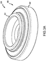
- a disk stack 300 of multilayer piston insulator 200 is illustrated in perspective ( FIG. 3A ) and in cross section through the XY-plane ( FIG. 3B ).
- Disk stack 300 comprises a plurality of axially aligned disks coupled about the circumference of the disk stack 300 by a retaining band 302.
- the disk stack 300 may comprise a coupling feature 304 configured to interface the disk stack 300 to the piston 204.
- the disk stack 300 comprises a first disk 306, a second disk 308, and a third disk 310.
- the second disk 308 may be coupled relatively between the first disk 306 and the third disk 310.
- the first disk 306 may comprise a carbon material and include a raised contact ring 312 extending from a face of the first disk distal of the coupling feature 304.
- the second disk 308 may comprise a first annulus 314 and a first circumferential wall 316.
- the second disk 308 may comprise a different material than the first disk.
- the second disk 308 may comprise one of a steel, a stainless steel, a tungsten carbide, a titanium, a titanium alloy, a nickel, nickel alloy, a nickel steel (e.g., an austenitic nickel-chromium-based alloy such as that available under the trade name INCONEL), a silicate, or a ceramic.
- the first circumferential wall 316 extends perpendicular to the second disk proximate the outer diameter of the second disk.
- the first circumferential wall 316 may define a disk cup 320 configured to retain the first disk 306.
- the first disk 306 may be disposed within the disk cup 320 and, in response, axially aligned with the second disk 308.
- the third disk 310 may comprise a second annulus 322 and a second circumferential wall 324.
- the second circumferential wall 324 extends perpendicular to the third disk 310 proximate an outer diameter of the third disk 310.
- the second disk 308 may comprise a coupling portion 326 configured to interface with the second circumferential wall 324.
- the second circumferential wall 324 may be defined by the coupling portion 326.
- the second circumferential wall 324 may be configured to axially align the third disk 310 and the second disk 308 in response to coupling the third disk 310 at the coupling portion 326 of the second disk 308.
- the first annulus 314 has a diameter relatively less than that of the second annulus 322.
- an annular extrusion 328 may extend about second annulus 322 perpendicular to the third disk 310.
- the annular extrusion 328 may include a retaining ring channel 330 cut radially (along the X-axis) inward from an outer diameter of the annular extrusion 328.
- the third disk 310 may comprise the low thermal conductivity material or any of a steel, a stainless steel, a tungsten carbide, a titanium, a titanium alloy, a nickel, nickel alloy, a nickel steel (e.g., an austenitic nickel-chromium-based alloy such as that available under the trade name INCONEL), a silicate, or a ceramic.
- the disk stack 300 may be configured to inhibit conductive heat transfer between the first disk and the third disk by selection of disk materials having comparatively low coefficients of thermal conductivity.
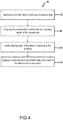
- a method 400 of manufacturing a multilayer piston insulator may comprise disposing first disk 306 within disk cup 320 of the second disk 308 (step 402).
- the first disk 306 may comprise a carbon material.
- Method 400 includes coupling the second disk 308 to the third disk 310 at the coupling portion 326 of the second disk 308 (step 404).
- Method 400 includes axially aligning (e.g., disk centers along the Y-axis) each of the first disk 306, the second disk 308, and the third disk 310 in response to the coupling (step 406).
- Method 400 includes applying the retaining band 302 circumferentially about each of first disk 306, the second disk 308, and the third disk 310 to form the disk stack 300 (step 408).
- references to “one embodiment”, “an embodiment”, “an example embodiment”, etc. indicate that the embodiment described may include a particular feature, structure, or characteristic, but every embodiment may not necessarily include the particular feature, structure, or characteristic. Moreover, such phrases are not necessarily referring to the same embodiment. Further, when a particular feature, structure, or characteristic is described in connection with an embodiment, it is submitted that it is within the knowledge of one skilled in the art to affect such feature, structure, or characteristic in connection with other embodiments whether or not explicitly described. After reading the description, it will be apparent to one skilled in the relevant art(s) how to implement the disclosure in alternative embodiment
Landscapes
- Engineering & Computer Science (AREA)
- General Engineering & Computer Science (AREA)
- Mechanical Engineering (AREA)
- Chemical & Material Sciences (AREA)
- Combustion & Propulsion (AREA)
- Aviation & Aerospace Engineering (AREA)
- Ceramic Engineering (AREA)
- Braking Arrangements (AREA)
Abstract
Description
- The disclosure relates generally to aircraft brake systems and aircraft brake actuation systems.
- Aircraft often include one or more landing gear that comprise one or more wheels. A braking system may typically be coupled to the wheel(s) in order to decelerate or park the aircraft. Aircraft braking may induce heating in hydraulic system components which tend to elevate hydraulic fluid temperatures. Elevated hydraulic fluid temperatures tend to promote hydraulic fluid seal degradation and fluid leakage, thereby decreasing system reliability and performance.
- In various embodiments the present disclosure provides a multilayer piston insulator comprising a plurality of axially aligned disks of a disk stack including at least, a first disk, a second disk, and a third disk, wherein the second disk is coupled relatively between the first disk and the third disk and configured to inhibit conductive heat transfer between the first disk and the third disk, and wherein the disk stack is configured to couple to a hydraulic piston.
- In various embodiments, the first disk comprises a carbon material. In various embodiments, at least one of the second disk or the third disk comprises one of a steel, a stainless steel, a tungsten carbide, a titanium, a titanium alloy, a nickel, nickel alloy, a nickel steel, a silicate, or a ceramic. In various embodiments, the second disk comprises a first annulus and the third disk comprises a second annulus. In various embodiments, the first annulus has a diameter relatively lesser than that of the second annulus. In various embodiments, the second disk comprises a first circumferential wall extending perpendicular to the second disk proximate an outer diameter of the second disk defining a disk cup. In various embodiments, the first disk is disposed within the disk cup defined by the first circumferential wall. In various embodiments, the third disk comprises a second circumferential wall extending perpendicular to the third disk proximate an outer diameter of the third disk, wherein the second circumferential wall is defined by a coupling portion of the second disk. In various embodiments, the third disk comprises an annular extrusion perpendicular to the disk about the second annulus, wherein the annular extrusion comprises a retaining ring channel. In various embodiments, each of the plurality of axially aligned disks are coupled by a retaining band applied circumferentially about the disk stack.
- In various embodiments the present disclosure provides a brake assembly for mounting on an axle comprising a brake friction stack, a wheel comprising a hub coupled to the axle, a torque bar configured to engage with the wheel and rotate the brake rotor, and an actuator assembly configured to apply brake pressure to the brake friction stack including a multilayer piston insulator, comprising a plurality of axially aligned disks of a disk stack including at least, a first disk, a second disk, and a third disk, wherein the second disk is coupled relatively between the first disk and the third disk and configured to inhibit conductive heat transfer between the first disk and the third disk, and wherein the disk stack is configured to couple to a hydraulic piston.
- In various embodiments, each of the plurality of axially aligned disks are coupled by a retaining band applied circumferentially about the disk stack. In various embodiments, the first disk comprises a carbon material and at least one of the second disk or the third disk comprises one of a steel, a stainless steel, a tungsten carbide, a titanium, a titanium alloy, a nickel, nickel alloy, a nickel steel, a silicate, or a ceramic. In various embodiments, the second disk comprises a first annulus and the third disk comprises a second annulus. In various embodiments, the first annulus has a diameter relatively lesser than that of the second annulus. In various embodiments, the second disk comprises a first circumferential wall extending perpendicular to the second disk proximate an outer diameter of the second disk defining a disk cup. In various embodiments, the first disk is disposed within the disk cup defined by the first circumferential wall. In various embodiments, the third disk comprises a second circumferential wall extending perpendicular to the third disk proximate an outer diameter of the third disk, wherein the second circumferential wall is defined by a coupling portion of the second disk. In various embodiments, the third disk comprises an annular extrusion perpendicular to the disk about the second annulus, wherein the annular extrusion comprises a retaining ring channel.
- In various embodiments, the present disclosure provides a method of manufacturing a multilayer piston insulator comprising disposing a first disk of a carbon material within a disk cup of a second disk, coupling the second disk to a third disk at a coupling portion of the second disk, axially aligning each of the first disk, the second disk, and the third disk in response to the coupling, and applying a retaining band circumferentially about each of the first disk, the second disk, and the third disk to form a disk stack.
- The forgoing features and elements may be combined in various combinations without exclusivity, unless expressly indicated herein otherwise. These features and elements as well as the operation of the disclosed embodiments will become more apparent in light of the following description and accompanying drawings.
- The subject matter of the present disclosure is particularly pointed out and distinctly claimed in the concluding portion of the specification. A more complete understanding of the present disclosures, however, may best be obtained by referring to the detailed description and claims when considered in connection with the drawing figures, wherein like numerals denote like elements.
-
FIG. 1A illustrates an aircraft having a wheel and brake system comprising a multilayer piston insulator, in accordance with various embodiments; -
FIG. 1B illustrates a wheel and brake assembly for mounting on an axle comprising a multilayer piston insulator, in accordance with various embodiments; -
FIG. 2 illustrates an actuator assembly including a multilayer piston insulator, in accordance with various embodiments; -
FIG. 3A illustrates a multilayer piston insulator, in accordance with various embodiments; -
FIG. 3B illustrates a multilayer piston insulator, in accordance with various embodiments; and -
FIG. 4 illustrates a method of manufacturing a multilayer piston insulator, in accordance with various embodiments. - The detailed description of exemplary embodiments herein makes reference to the accompanying drawings, which show exemplary embodiments by way of illustration and their best mode. While these exemplary embodiments are described in sufficient detail to enable those skilled in the art to practice the disclosures, it should be understood that other embodiments may be realized and that logical, chemical, and mechanical changes may be made without departing from the spirit and scope of the disclosures. Thus, the detailed description herein is presented for purposes of illustration only and not of limitation. For example, the steps recited in any of the method or process descriptions may be executed in any order and are not necessarily limited to the order presented. Furthermore, any reference to singular includes plural embodiments, and any reference to more than one component or step may include a singular embodiment or step. Also, any reference to attached, fixed, connected or the like may include permanent, removable, temporary, partial, full and/or any other possible attachment option. Additionally, any reference to without contact (or similar phrases) may also include reduced contact or minimal contact.
- Referring now to
FIG. 1A , in accordance with various embodiments, anaircraft 10 includes landing gear, such as a leftmain landing gear 12, a rightmain landing gear 14, andnose landing gear 16. The leftmain landing gear 12, rightmain landing gear 14, andnose landing gear 16 typically support theaircraft 10 when theaircraft 10 is not flying, thereby allowing theaircraft 10 to taxi, take off, and land without damage. In various embodiments, the leftmain landing gear 12 includes afirst wheel 13A and asecond wheel 13B coupled by anaxle 20. In various embodiments, the rightmain landing gear 14 includes afirst wheel 15A and asecond wheel 15B coupled by anaxle 22. In various embodiments, thenose landing gear 16 includes afirst nose wheel 17A and asecond nose wheel 17B coupled by anaxle 24. In various embodiments, theaircraft 10 comprises any number of landing gear(s), and each landing gear comprises any number of wheels. In various embodiments, the leftmain landing gear 12, rightmain landing gear 14, andnose landing gear 16 are retracted when theaircraft 10 is in flight. In various embodiments, one or more of the leftmain landing gear 12, rightmain landing gear 14, andnose landing gear 16 extends from an underside of afuselage 28 of theaircraft 10, or from an underside of the wings 30 thereof. - In various embodiments, the
aircraft 10 also includes a brake system that is applied to one or more of thewheels main landing gear 12, rightmain landing gear 14, and/ornose landing gear 16. Referring now toFIG. 1B , a wheel and brake assembly for mounting on anaxle 110 comprising amultilayer piston insulator 200 is located on theaircraft 10 ofFIG. 1-A , in accordance with various embodiments. The wheel and brake assembly for mounting on anaxle 110 typically comprises abogie axle 112, a wheel 114 (e.g., thewheels FIG. 1-A ) including ahub 116 andwheel well 118, aweb 120, a torque take-out assembly 122, one ormore torque bars 124, a wheelrotational axis 126, a wheel well recess 128, anactuator assembly 130,multiple brake rotors 32,multiple brake stators 34, apressure plate 36, anend plate 38, aheat shield 140 which may havesections 142, multipleheat shield carriers 144, anair gap 146, multipletorque bar bolts 148, atorque bar pin 151, awheel web hole 152, multipleheat shield fasteners 153,multiple rotor lugs 154, andmultiple stator slots 156. - Brake disks (e.g., the
interleaved brake rotors 32 and brake stators 34) comprise a brake friction stack disposed in the wheel well recess 128 of the wheel well 118. Thebrake rotors 32 are typically engaged to the torque bars 124 for rotating with thewheel 114, while thebrake stators 34 are typically engaged with the torque take-outassembly 122. At least oneactuator assembly 130 is typically operable to compress the interleavedbrake rotors 32 andbrake stators 34 for stopping theaircraft 10 ofFIG. 1A . In the embodiment ofFIG. 1B , theactuator assembly 130 is shown as a comprising a hydraulically actuated piston. Thepressure plate 36 andend plate 38 are disposed at opposite ends of the interleavedbrake rotors 32 andbrake stators 34. - Through compression of the
brake rotors 32 andbrake stators 34 between thepressure plate 36 andend plate 38, the resulting frictional contact slows, stops, and/or prevents rotation of thewheel 114. The torque take-outassembly 122 is typically secured to a stationary portion of a landing gear truck, such as a bogie beam or other landing gear strut, such that the torque take-outassembly 122 andbrake stators 34 are prevented from rotating during braking of theaircraft 10 ofFIG. 1A . Thebrake rotors 32 andbrake stators 34 are typically fabricated from various materials, such as, for example carbon materials. The brake disks typically withstand and dissipate the heat generated from friction between the brake disks while braking theaircraft 10 ofFIG. 1A . The frictional contact tends to heat the rotors and stators in excess of 1000 °F [538 °C]. - According to various embodiments and with reference to
FIGS. 1 and2 ,actuator assembly 130 is illustrated in cross section through the XY-plan and comprising themultilayer piston insulator 200. Theactuator assembly 130 comprises apiston housing 202 and apiston 204 configurated to translate axially (along the X-axis) within thepiston housing 202 in response to hydraulic pressure.Piston 204 comprises an annular-cylindrical structure 206 extending from thepiston base wall 208 toward themultilayer piston insulator 200. Themultilayer piston insulator 200 is coupled to the annular-cylindrical structure 206 opposite thepiston base wall 208 by a retainingring 210. Hydraulic fluid enterscavity 212 behindpiston base wall 208 and is retained byseal member 214. The hydraulic fluid exerts hydraulic pressure on thepiston 204, causing themultilayer piston insulator 200 to contact thepressure plate 36 and exert brake pressure on thebrake rotors 32 andbrake stators 34. In response, thepressure plate 36 tends to undergo heating and themultilayer piston insulator 200 may tend to mitigate conductive heat transfer between thepressure plate 36 and the annular-cylindrical structure 206 ofpiston 204. In this regard, conductive heat transfer between thepiston base wall 208 and the hydraulic fluid may be reduced. - With reference now to
FIGs. 3A and3B , in various embodiments, adisk stack 300 ofmultilayer piston insulator 200 is illustrated in perspective (FIG. 3A ) and in cross section through the XY-plane (FIG. 3B ).Disk stack 300 comprises a plurality of axially aligned disks coupled about the circumference of thedisk stack 300 by a retainingband 302. Thedisk stack 300 may comprise acoupling feature 304 configured to interface thedisk stack 300 to thepiston 204. In various embodiments, thedisk stack 300 comprises afirst disk 306, asecond disk 308, and athird disk 310. Thesecond disk 308 may be coupled relatively between thefirst disk 306 and thethird disk 310. Thefirst disk 306 may comprise a carbon material and include a raisedcontact ring 312 extending from a face of the first disk distal of thecoupling feature 304. - In various embodiments the
second disk 308 may comprise afirst annulus 314 and a firstcircumferential wall 316. Thesecond disk 308 may comprise a different material than the first disk. In various embodiments, thesecond disk 308 may comprise one of a steel, a stainless steel, a tungsten carbide, a titanium, a titanium alloy, a nickel, nickel alloy, a nickel steel (e.g., an austenitic nickel-chromium-based alloy such as that available under the trade name INCONEL), a silicate, or a ceramic. In various embodiments the firstcircumferential wall 316 extends perpendicular to the second disk proximate the outer diameter of the second disk. In this regard, the firstcircumferential wall 316 may define adisk cup 320 configured to retain thefirst disk 306. In various embodiments, thefirst disk 306 may be disposed within thedisk cup 320 and, in response, axially aligned with thesecond disk 308. - In like regard, the
third disk 310 may comprise asecond annulus 322 and a secondcircumferential wall 324. The secondcircumferential wall 324 extends perpendicular to thethird disk 310 proximate an outer diameter of thethird disk 310. In various embodiments, thesecond disk 308 may comprise acoupling portion 326 configured to interface with the secondcircumferential wall 324. In this regard, the secondcircumferential wall 324 may be defined by thecoupling portion 326. The secondcircumferential wall 324 may be configured to axially align thethird disk 310 and thesecond disk 308 in response to coupling thethird disk 310 at thecoupling portion 326 of thesecond disk 308. In various embodiments, thefirst annulus 314 has a diameter relatively less than that of thesecond annulus 322. In various embodiments, an annular extrusion 328 may extend aboutsecond annulus 322 perpendicular to thethird disk 310. The annular extrusion 328 may include a retainingring channel 330 cut radially (along the X-axis) inward from an outer diameter of the annular extrusion 328. In various embodiments, thethird disk 310 may comprise the low thermal conductivity material or any of a steel, a stainless steel, a tungsten carbide, a titanium, a titanium alloy, a nickel, nickel alloy, a nickel steel (e.g., an austenitic nickel-chromium-based alloy such as that available under the trade name INCONEL), a silicate, or a ceramic. In this regard, thedisk stack 300 may be configured to inhibit conductive heat transfer between the first disk and the third disk by selection of disk materials having comparatively low coefficients of thermal conductivity. - In various embodiments and with additional reference now to
FIG. 4 , amethod 400 of manufacturing a multilayer piston insulator may comprise disposingfirst disk 306 withindisk cup 320 of the second disk 308 (step 402). Thefirst disk 306 may comprise a carbon material.Method 400 includes coupling thesecond disk 308 to thethird disk 310 at thecoupling portion 326 of the second disk 308 (step 404).Method 400 includes axially aligning (e.g., disk centers along the Y-axis) each of thefirst disk 306, thesecond disk 308, and thethird disk 310 in response to the coupling (step 406).Method 400 includes applying the retainingband 302 circumferentially about each offirst disk 306, thesecond disk 308, and thethird disk 310 to form the disk stack 300 (step 408). - Benefits, other advantages, and solutions to problems have been described herein with regard to specific embodiments. Furthermore, the connecting lines shown in the various figures contained herein are intended to represent exemplary functional relationships and/or physical couplings between the various elements. It should be noted that many alternative or additional functional relationships or physical connections may be present in a practical system. However, the benefits, advantages, solutions to problems, and any elements that may cause any benefit, advantage, or solution to occur or become more pronounced are not to be construed as critical, required, or essential features or elements of the disclosures.
- The scope of the disclosures is accordingly to be limited by nothing other than the appended claims, in which reference to an element in the singular is not intended to mean "one and only one" unless explicitly so stated, but rather "one or more." Moreover, where a phrase similar to "at least one of A, B, or C" is used in the claims, it is intended that the phrase be interpreted to mean that A alone may be present in an embodiment, B alone may be present in an embodiment, C alone may be present in an embodiment, or that any combination of the elements A, B and C may be present in a single embodiment; for example, A and B, A and C, B and C, or A and B and C. Different cross-hatching is used throughout the figures to denote different parts but not necessarily to denote the same or different materials.
- Systems, methods and apparatus are provided herein. In the detailed description herein, references to "one embodiment", "an embodiment", "an example embodiment", etc., indicate that the embodiment described may include a particular feature, structure, or characteristic, but every embodiment may not necessarily include the particular feature, structure, or characteristic. Moreover, such phrases are not necessarily referring to the same embodiment. Further, when a particular feature, structure, or characteristic is described in connection with an embodiment, it is submitted that it is within the knowledge of one skilled in the art to affect such feature, structure, or characteristic in connection with other embodiments whether or not explicitly described. After reading the description, it will be apparent to one skilled in the relevant art(s) how to implement the disclosure in alternative embodiment
- Furthermore, no element, component, or method step in the present disclosure is intended to be dedicated to the public regardless of whether the element, component, or method step is explicitly recited in the claims. As used herein, the terms "comprises", "comprising", or any other variation thereof, are intended to cover a non-exclusive inclusion, such that a process, method, article, or apparatus that comprises a list of elements does not include only those elements but may include other elements not expressly listed or inherent to such process, method, article, or apparatus.
Claims (12)
- A multilayer piston insulator (200), comprising:a plurality of axially aligned disks of a disk stack (300) comprising a first disk (306), a second disk (308), and a third disk (310),wherein the second disk is coupled coaxially between the first disk and the third disk and comprises a different material than the first disk and the third disk, andwherein the disk stack is configured to couple to a hydraulic piston (204).
- The multilayer piston insulator of claim 1, wherein the first disk comprises a carbon material.
- The multilayer piston insulator of any preceding claim, wherein at least one of the second disk or the third disk comprises one of a steel, a stainless steel, a tungsten carbide, a titanium, a titanium alloy, a nickel, nickel alloy, a nickel steel, a silicate, or a ceramic.
- The multilayer piston insulator of any preceding claim, wherein the second disk comprises a first annulus and the third disk comprises a second annulus.
- The multilayer piston insulator of claim 4, wherein the first annulus has a diameter relatively lesser than that of the second annulus.
- The multilayer piston insulator of any preceding claim, wherein the second disk comprises a first circumferential wall extending perpendicular to the second disk proximate an outer diameter of the second disk defining a disk cup.
- The multilayer piston insulator of claim 6, wherein the first disk is disposed within the disk cup defined by the first circumferential wall.
- The multilayer piston insulator of claim 6 or 7, wherein the third disk comprises a second circumferential wall extending perpendicular to the third disk proximate an outer diameter of the third disk, wherein the second circumferential wall is defined by a coupling portion of the second disk.
- The multilayer piston insulator of claim 4, wherein the third disk comprises an annular extrusion perpendicular to the third disk about the second annulus, wherein the annular extrusion comprises a retaining ring channel.
- The multilayer piston insulator of any preceding claim, wherein each of the plurality of axially aligned disks are coupled by a retaining band applied circumferentially about the disk stack.
- A wheel and brake assembly for mounting on an axle, comprising:a brake friction stack;a wheel (114) comprising a hub (116) coupled to the axle (110);a torque bar (124) configured to engage with the wheel and rotate the brake rotor; andan actuator assembly (130) configured to apply brake pressure to the brake friction stack including the multilayer piston insulator (200) according to any preceding claim.
- A method (400) of manufacturing a multilayer piston insulator (200), the method comprising:disposing (402) a first disk (306) of a carbon material within a disk cup of a second disk (208);coupling (404) the second disk to a third disk (310) at a coupling portion of the second disk;axially aligning (406) each of the first disk, the second disk, and the third disk in response to the coupling; andapplying (408) a retaining band (302) circumferentially about each of the first disk, the second disk, and the third disk to form a disk stack.
Applications Claiming Priority (1)
| Application Number | Priority Date | Filing Date | Title |
|---|---|---|---|
| US16/384,567 US10941825B2 (en) | 2019-04-15 | 2019-04-15 | Multiple layer piston insulator for hydraulic brake actuator |
Publications (2)
| Publication Number | Publication Date |
|---|---|
| EP3726087A1 true EP3726087A1 (en) | 2020-10-21 |
| EP3726087B1 EP3726087B1 (en) | 2022-03-16 |
Family
ID=68808056
Family Applications (1)
| Application Number | Title | Priority Date | Filing Date |
|---|---|---|---|
| EP19213946.7A Active EP3726087B1 (en) | 2019-04-15 | 2019-12-05 | Multiple layer piston insulator for hydraulic brake actuator |
Country Status (2)
| Country | Link |
|---|---|
| US (1) | US10941825B2 (en) |
| EP (1) | EP3726087B1 (en) |
Families Citing this family (3)
| Publication number | Priority date | Publication date | Assignee | Title |
|---|---|---|---|---|
| US10941825B2 (en) * | 2019-04-15 | 2021-03-09 | Goodrich Corporation | Multiple layer piston insulator for hydraulic brake actuator |
| US12305726B2 (en) * | 2022-06-06 | 2025-05-20 | Goodrich Corporation | Multi-layer aircraft brake insulator |
| US12416342B2 (en) * | 2022-07-01 | 2025-09-16 | Goodrich Corporation | Failsafe piston pressure path |
Citations (3)
| Publication number | Priority date | Publication date | Assignee | Title |
|---|---|---|---|---|
| WO2002099305A1 (en) * | 2001-06-04 | 2002-12-12 | Freni Brembo S.P.A. | Brake piston |
| US20040094375A1 (en) * | 2002-11-15 | 2004-05-20 | Wenqi Qian | Piston having a cap and a brake caliper for use therewith |
| DE202010009547U1 (en) * | 2010-06-25 | 2010-09-16 | Nies, Klaus-Dieter | Insulation for thermal decoupling of two adjacent components |
Family Cites Families (19)
| Publication number | Priority date | Publication date | Assignee | Title |
|---|---|---|---|---|
| BR7804660A (en) * | 1977-07-20 | 1979-03-06 | Girling Ltd | BOOT ASSEMBLY AND DISC BRAKE INCORPORATING THE SAME |
| US4147241A (en) | 1977-10-27 | 1979-04-03 | The Bendix Corporation | Structurally strong heat insulator for high transient temperatures |
| US4537289A (en) * | 1982-06-18 | 1985-08-27 | International Telephone And Telegraph Corporation | Dust boot for a disc-brake actuating cylinder-and-piston unit |
| JPS5929828A (en) * | 1982-08-12 | 1984-02-17 | Nissan Motor Co Ltd | Disc brake |
| US4513844A (en) * | 1982-09-07 | 1985-04-30 | General Motors Corporation | Disc brake shoe retainer assembly with insulation |
| US4596317A (en) * | 1985-01-14 | 1986-06-24 | General Motors Corporation | Disc brake piston and brake pad assembly |
| US4603760A (en) * | 1985-09-03 | 1986-08-05 | General Motors Corporation | Slotted insulator and disc brake assembly using same |
| US4848291A (en) * | 1987-05-30 | 1989-07-18 | Isuzu Motors Limited | Heat-insulating piston structure |
| US5205382A (en) * | 1990-10-09 | 1993-04-27 | The B. F. Goodrich Company | Aircraft brake |
| US5538109A (en) | 1990-12-04 | 1996-07-23 | The B. F. Goodrich Company | Piston head for an aircraft brake and insulator |
| JPH1037990A (en) * | 1996-07-18 | 1998-02-13 | Nisshinbo Ind Inc | Disc pad |
| US5988044A (en) * | 1998-03-06 | 1999-11-23 | Occidental Chemical Corporation | Piston having insulated cap |
| DE10234642B4 (en) * | 2002-07-29 | 2020-11-05 | Knorr-Bremse Systeme für Nutzfahrzeuge GmbH | Disc brake and thermal insulation device for a disc brake |
| US7905333B2 (en) * | 2006-08-08 | 2011-03-15 | Material Sciences Corporation | Brake insulator for disc brake pads |
| CA2645460C (en) * | 2008-11-28 | 2015-12-29 | Ray Arbesman | Piston-side brake shim |
| IT1402553B1 (en) * | 2010-11-04 | 2013-09-13 | Kematis Projects Ltd | THERMO-INSULATING BODY FOR BRAKING GROUP |
| DE102016112485B4 (en) * | 2016-07-07 | 2025-04-30 | Dr. Ing. H.C. F. Porsche Aktiengesellschaft | Device for thermal insulation on a disc brake actuator |
| US10968971B2 (en) * | 2018-08-13 | 2021-04-06 | Goodrich Corporation | Multi-layer insulator for brake piston |
| US10941825B2 (en) * | 2019-04-15 | 2021-03-09 | Goodrich Corporation | Multiple layer piston insulator for hydraulic brake actuator |
-
2019
- 2019-04-15 US US16/384,567 patent/US10941825B2/en active Active
- 2019-12-05 EP EP19213946.7A patent/EP3726087B1/en active Active
Patent Citations (3)
| Publication number | Priority date | Publication date | Assignee | Title |
|---|---|---|---|---|
| WO2002099305A1 (en) * | 2001-06-04 | 2002-12-12 | Freni Brembo S.P.A. | Brake piston |
| US20040094375A1 (en) * | 2002-11-15 | 2004-05-20 | Wenqi Qian | Piston having a cap and a brake caliper for use therewith |
| DE202010009547U1 (en) * | 2010-06-25 | 2010-09-16 | Nies, Klaus-Dieter | Insulation for thermal decoupling of two adjacent components |
Also Published As
| Publication number | Publication date |
|---|---|
| US10941825B2 (en) | 2021-03-09 |
| US20200325948A1 (en) | 2020-10-15 |
| EP3726087B1 (en) | 2022-03-16 |
Similar Documents
| Publication | Publication Date | Title |
|---|---|---|
| EP3480072B1 (en) | Shield attachment device | |
| EP3521161B1 (en) | Laminated dimpled foil metallic heat shield | |
| EP3670955B1 (en) | Heat shield retainer and method | |
| EP3767125B1 (en) | Heat shield retainer and methods | |
| US10941825B2 (en) | Multiple layer piston insulator for hydraulic brake actuator | |
| EP3734104A1 (en) | Hydraulic brake actuator piston adjuster assembly | |
| EP3524517B1 (en) | Insulated torque plate foot assembly | |
| EP4283153B1 (en) | Reduced drag stator clip | |
| EP3453612B1 (en) | Aircraft brake torque load reaction through landing gear bogie structure | |
| US10309468B2 (en) | Torque plate barrel having blended barrel support pedestal | |
| EP3404283A1 (en) | Extended torque tube | |
| EP3925874A1 (en) | Aircraft wheel torque bar spacer | |
| US20200309210A1 (en) | Brake assembly with disks of variable thickness and methods for disk reuse | |
| EP3441637A1 (en) | Differential torque plate barrel thickness | |
| US10400839B1 (en) | Aircraft brake heat shield | |
| EP4414581B1 (en) | Use of profiled reaction face in hybrid torque bar applications | |
| EP4306821A1 (en) | Heat retaining shield clasp | |
| EP4321768A1 (en) | Tapered torque plate barrel for improving dynamic stability | |
| EP3978776B1 (en) | Carbon brake stack assembly for improved life |
Legal Events
| Date | Code | Title | Description |
|---|---|---|---|
| PUAI | Public reference made under article 153(3) epc to a published international application that has entered the european phase |
Free format text: ORIGINAL CODE: 0009012 |
|
| STAA | Information on the status of an ep patent application or granted ep patent |
Free format text: STATUS: THE APPLICATION HAS BEEN PUBLISHED |
|
| AK | Designated contracting states |
Kind code of ref document: A1 Designated state(s): AL AT BE BG CH CY CZ DE DK EE ES FI FR GB GR HR HU IE IS IT LI LT LU LV MC MK MT NL NO PL PT RO RS SE SI SK SM TR |
|
| AX | Request for extension of the european patent |
Extension state: BA ME |
|
| STAA | Information on the status of an ep patent application or granted ep patent |
Free format text: STATUS: REQUEST FOR EXAMINATION WAS MADE |
|
| 17P | Request for examination filed |
Effective date: 20210421 |
|
| RBV | Designated contracting states (corrected) |
Designated state(s): AL AT BE BG CH CY CZ DE DK EE ES FI FR GB GR HR HU IE IS IT LI LT LU LV MC MK MT NL NO PL PT RO RS SE SI SK SM TR |
|
| GRAP | Despatch of communication of intention to grant a patent |
Free format text: ORIGINAL CODE: EPIDOSNIGR1 |
|
| STAA | Information on the status of an ep patent application or granted ep patent |
Free format text: STATUS: GRANT OF PATENT IS INTENDED |
|
| INTG | Intention to grant announced |
Effective date: 20211019 |
|
| GRAS | Grant fee paid |
Free format text: ORIGINAL CODE: EPIDOSNIGR3 |
|
| GRAA | (expected) grant |
Free format text: ORIGINAL CODE: 0009210 |
|
| STAA | Information on the status of an ep patent application or granted ep patent |
Free format text: STATUS: THE PATENT HAS BEEN GRANTED |
|
| AK | Designated contracting states |
Kind code of ref document: B1 Designated state(s): AL AT BE BG CH CY CZ DE DK EE ES FI FR GB GR HR HU IE IS IT LI LT LU LV MC MK MT NL NO PL PT RO RS SE SI SK SM TR |
|
| REG | Reference to a national code |
Ref country code: GB Ref legal event code: FG4D |
|
| REG | Reference to a national code |
Ref country code: CH Ref legal event code: EP |
|
| REG | Reference to a national code |
Ref country code: DE Ref legal event code: R096 Ref document number: 602019012570 Country of ref document: DE |
|
| REG | Reference to a national code |
Ref country code: IE Ref legal event code: FG4D |
|
| REG | Reference to a national code |
Ref country code: AT Ref legal event code: REF Ref document number: 1476083 Country of ref document: AT Kind code of ref document: T Effective date: 20220415 |
|
| REG | Reference to a national code |
Ref country code: LT Ref legal event code: MG9D |
|
| REG | Reference to a national code |
Ref country code: NL Ref legal event code: MP Effective date: 20220316 |
|
| PG25 | Lapsed in a contracting state [announced via postgrant information from national office to epo] |
Ref country code: SE Free format text: LAPSE BECAUSE OF FAILURE TO SUBMIT A TRANSLATION OF THE DESCRIPTION OR TO PAY THE FEE WITHIN THE PRESCRIBED TIME-LIMIT Effective date: 20220316 Ref country code: RS Free format text: LAPSE BECAUSE OF FAILURE TO SUBMIT A TRANSLATION OF THE DESCRIPTION OR TO PAY THE FEE WITHIN THE PRESCRIBED TIME-LIMIT Effective date: 20220316 Ref country code: NO Free format text: LAPSE BECAUSE OF FAILURE TO SUBMIT A TRANSLATION OF THE DESCRIPTION OR TO PAY THE FEE WITHIN THE PRESCRIBED TIME-LIMIT Effective date: 20220616 Ref country code: LT Free format text: LAPSE BECAUSE OF FAILURE TO SUBMIT A TRANSLATION OF THE DESCRIPTION OR TO PAY THE FEE WITHIN THE PRESCRIBED TIME-LIMIT Effective date: 20220316 Ref country code: HR Free format text: LAPSE BECAUSE OF FAILURE TO SUBMIT A TRANSLATION OF THE DESCRIPTION OR TO PAY THE FEE WITHIN THE PRESCRIBED TIME-LIMIT Effective date: 20220316 Ref country code: BG Free format text: LAPSE BECAUSE OF FAILURE TO SUBMIT A TRANSLATION OF THE DESCRIPTION OR TO PAY THE FEE WITHIN THE PRESCRIBED TIME-LIMIT Effective date: 20220616 |
|
| REG | Reference to a national code |
Ref country code: AT Ref legal event code: MK05 Ref document number: 1476083 Country of ref document: AT Kind code of ref document: T Effective date: 20220316 |
|
| PG25 | Lapsed in a contracting state [announced via postgrant information from national office to epo] |
Ref country code: LV Free format text: LAPSE BECAUSE OF FAILURE TO SUBMIT A TRANSLATION OF THE DESCRIPTION OR TO PAY THE FEE WITHIN THE PRESCRIBED TIME-LIMIT Effective date: 20220316 Ref country code: GR Free format text: LAPSE BECAUSE OF FAILURE TO SUBMIT A TRANSLATION OF THE DESCRIPTION OR TO PAY THE FEE WITHIN THE PRESCRIBED TIME-LIMIT Effective date: 20220617 Ref country code: FI Free format text: LAPSE BECAUSE OF FAILURE TO SUBMIT A TRANSLATION OF THE DESCRIPTION OR TO PAY THE FEE WITHIN THE PRESCRIBED TIME-LIMIT Effective date: 20220316 |
|
| PG25 | Lapsed in a contracting state [announced via postgrant information from national office to epo] |
Ref country code: NL Free format text: LAPSE BECAUSE OF FAILURE TO SUBMIT A TRANSLATION OF THE DESCRIPTION OR TO PAY THE FEE WITHIN THE PRESCRIBED TIME-LIMIT Effective date: 20220316 |
|
| PG25 | Lapsed in a contracting state [announced via postgrant information from national office to epo] |
Ref country code: SM Free format text: LAPSE BECAUSE OF FAILURE TO SUBMIT A TRANSLATION OF THE DESCRIPTION OR TO PAY THE FEE WITHIN THE PRESCRIBED TIME-LIMIT Effective date: 20220316 Ref country code: SK Free format text: LAPSE BECAUSE OF FAILURE TO SUBMIT A TRANSLATION OF THE DESCRIPTION OR TO PAY THE FEE WITHIN THE PRESCRIBED TIME-LIMIT Effective date: 20220316 Ref country code: RO Free format text: LAPSE BECAUSE OF FAILURE TO SUBMIT A TRANSLATION OF THE DESCRIPTION OR TO PAY THE FEE WITHIN THE PRESCRIBED TIME-LIMIT Effective date: 20220316 Ref country code: PT Free format text: LAPSE BECAUSE OF FAILURE TO SUBMIT A TRANSLATION OF THE DESCRIPTION OR TO PAY THE FEE WITHIN THE PRESCRIBED TIME-LIMIT Effective date: 20220718 Ref country code: ES Free format text: LAPSE BECAUSE OF FAILURE TO SUBMIT A TRANSLATION OF THE DESCRIPTION OR TO PAY THE FEE WITHIN THE PRESCRIBED TIME-LIMIT Effective date: 20220316 Ref country code: EE Free format text: LAPSE BECAUSE OF FAILURE TO SUBMIT A TRANSLATION OF THE DESCRIPTION OR TO PAY THE FEE WITHIN THE PRESCRIBED TIME-LIMIT Effective date: 20220316 Ref country code: CZ Free format text: LAPSE BECAUSE OF FAILURE TO SUBMIT A TRANSLATION OF THE DESCRIPTION OR TO PAY THE FEE WITHIN THE PRESCRIBED TIME-LIMIT Effective date: 20220316 Ref country code: AT Free format text: LAPSE BECAUSE OF FAILURE TO SUBMIT A TRANSLATION OF THE DESCRIPTION OR TO PAY THE FEE WITHIN THE PRESCRIBED TIME-LIMIT Effective date: 20220316 |
|
| PG25 | Lapsed in a contracting state [announced via postgrant information from national office to epo] |
Ref country code: PL Free format text: LAPSE BECAUSE OF FAILURE TO SUBMIT A TRANSLATION OF THE DESCRIPTION OR TO PAY THE FEE WITHIN THE PRESCRIBED TIME-LIMIT Effective date: 20220316 Ref country code: IS Free format text: LAPSE BECAUSE OF FAILURE TO SUBMIT A TRANSLATION OF THE DESCRIPTION OR TO PAY THE FEE WITHIN THE PRESCRIBED TIME-LIMIT Effective date: 20220716 Ref country code: AL Free format text: LAPSE BECAUSE OF FAILURE TO SUBMIT A TRANSLATION OF THE DESCRIPTION OR TO PAY THE FEE WITHIN THE PRESCRIBED TIME-LIMIT Effective date: 20220316 |
|
| REG | Reference to a national code |
Ref country code: DE Ref legal event code: R097 Ref document number: 602019012570 Country of ref document: DE |
|
| PLBE | No opposition filed within time limit |
Free format text: ORIGINAL CODE: 0009261 |
|
| STAA | Information on the status of an ep patent application or granted ep patent |
Free format text: STATUS: NO OPPOSITION FILED WITHIN TIME LIMIT |
|
| PG25 | Lapsed in a contracting state [announced via postgrant information from national office to epo] |
Ref country code: DK Free format text: LAPSE BECAUSE OF FAILURE TO SUBMIT A TRANSLATION OF THE DESCRIPTION OR TO PAY THE FEE WITHIN THE PRESCRIBED TIME-LIMIT Effective date: 20220316 |
|
| 26N | No opposition filed |
Effective date: 20221219 |
|
| PG25 | Lapsed in a contracting state [announced via postgrant information from national office to epo] |
Ref country code: SI Free format text: LAPSE BECAUSE OF FAILURE TO SUBMIT A TRANSLATION OF THE DESCRIPTION OR TO PAY THE FEE WITHIN THE PRESCRIBED TIME-LIMIT Effective date: 20220316 |
|
| P01 | Opt-out of the competence of the unified patent court (upc) registered |
Effective date: 20230522 |
|
| REG | Reference to a national code |
Ref country code: DE Ref legal event code: R119 Ref document number: 602019012570 Country of ref document: DE |
|
| PG25 | Lapsed in a contracting state [announced via postgrant information from national office to epo] |
Ref country code: IT Free format text: LAPSE BECAUSE OF FAILURE TO SUBMIT A TRANSLATION OF THE DESCRIPTION OR TO PAY THE FEE WITHIN THE PRESCRIBED TIME-LIMIT Effective date: 20220316 |
|
| REG | Reference to a national code |
Ref country code: CH Ref legal event code: PL |
|
| REG | Reference to a national code |
Ref country code: BE Ref legal event code: MM Effective date: 20221231 |
|
| PG25 | Lapsed in a contracting state [announced via postgrant information from national office to epo] |
Ref country code: LU Free format text: LAPSE BECAUSE OF NON-PAYMENT OF DUE FEES Effective date: 20221205 |
|
| PG25 | Lapsed in a contracting state [announced via postgrant information from national office to epo] |
Ref country code: LI Free format text: LAPSE BECAUSE OF NON-PAYMENT OF DUE FEES Effective date: 20221231 Ref country code: IE Free format text: LAPSE BECAUSE OF NON-PAYMENT OF DUE FEES Effective date: 20221205 Ref country code: DE Free format text: LAPSE BECAUSE OF NON-PAYMENT OF DUE FEES Effective date: 20230701 Ref country code: CH Free format text: LAPSE BECAUSE OF NON-PAYMENT OF DUE FEES Effective date: 20221231 |
|
| PG25 | Lapsed in a contracting state [announced via postgrant information from national office to epo] |
Ref country code: BE Free format text: LAPSE BECAUSE OF NON-PAYMENT OF DUE FEES Effective date: 20221231 |
|
| PG25 | Lapsed in a contracting state [announced via postgrant information from national office to epo] |
Ref country code: CY Free format text: LAPSE BECAUSE OF FAILURE TO SUBMIT A TRANSLATION OF THE DESCRIPTION OR TO PAY THE FEE WITHIN THE PRESCRIBED TIME-LIMIT Effective date: 20220316 |
|
| PG25 | Lapsed in a contracting state [announced via postgrant information from national office to epo] |
Ref country code: MK Free format text: LAPSE BECAUSE OF FAILURE TO SUBMIT A TRANSLATION OF THE DESCRIPTION OR TO PAY THE FEE WITHIN THE PRESCRIBED TIME-LIMIT Effective date: 20220316 Ref country code: HU Free format text: LAPSE BECAUSE OF FAILURE TO SUBMIT A TRANSLATION OF THE DESCRIPTION OR TO PAY THE FEE WITHIN THE PRESCRIBED TIME-LIMIT; INVALID AB INITIO Effective date: 20191205 |
|
| PG25 | Lapsed in a contracting state [announced via postgrant information from national office to epo] |
Ref country code: MC Free format text: LAPSE BECAUSE OF FAILURE TO SUBMIT A TRANSLATION OF THE DESCRIPTION OR TO PAY THE FEE WITHIN THE PRESCRIBED TIME-LIMIT Effective date: 20220316 |
|
| PG25 | Lapsed in a contracting state [announced via postgrant information from national office to epo] |
Ref country code: MC Free format text: LAPSE BECAUSE OF FAILURE TO SUBMIT A TRANSLATION OF THE DESCRIPTION OR TO PAY THE FEE WITHIN THE PRESCRIBED TIME-LIMIT Effective date: 20220316 |
|
| PG25 | Lapsed in a contracting state [announced via postgrant information from national office to epo] |
Ref country code: MT Free format text: LAPSE BECAUSE OF FAILURE TO SUBMIT A TRANSLATION OF THE DESCRIPTION OR TO PAY THE FEE WITHIN THE PRESCRIBED TIME-LIMIT Effective date: 20220316 |
|
| PG25 | Lapsed in a contracting state [announced via postgrant information from national office to epo] |
Ref country code: TR Free format text: LAPSE BECAUSE OF FAILURE TO SUBMIT A TRANSLATION OF THE DESCRIPTION OR TO PAY THE FEE WITHIN THE PRESCRIBED TIME-LIMIT Effective date: 20220316 |
|
| PGFP | Annual fee paid to national office [announced via postgrant information from national office to epo] |
Ref country code: GB Payment date: 20251120 Year of fee payment: 7 |
|
| PGFP | Annual fee paid to national office [announced via postgrant information from national office to epo] |
Ref country code: FR Payment date: 20251120 Year of fee payment: 7 |