EP3726080A1 - Sliding member and bearing - Google Patents
Sliding member and bearing Download PDFInfo
- Publication number
- EP3726080A1 EP3726080A1 EP18888609.7A EP18888609A EP3726080A1 EP 3726080 A1 EP3726080 A1 EP 3726080A1 EP 18888609 A EP18888609 A EP 18888609A EP 3726080 A1 EP3726080 A1 EP 3726080A1
- Authority
- EP
- European Patent Office
- Prior art keywords
- weight
- resin composition
- less
- friction force
- zinc
- Prior art date
- Legal status (The legal status is an assumption and is not a legal conclusion. Google has not performed a legal analysis and makes no representation as to the accuracy of the status listed.)
- Granted
Links
Images

Classifications
-
- F—MECHANICAL ENGINEERING; LIGHTING; HEATING; WEAPONS; BLASTING
- F16—ENGINEERING ELEMENTS AND UNITS; GENERAL MEASURES FOR PRODUCING AND MAINTAINING EFFECTIVE FUNCTIONING OF MACHINES OR INSTALLATIONS; THERMAL INSULATION IN GENERAL
- F16F—SPRINGS; SHOCK-ABSORBERS; MEANS FOR DAMPING VIBRATION
- F16F9/00—Springs, vibration-dampers, shock-absorbers, or similarly-constructed movement-dampers using a fluid or the equivalent as damping medium
- F16F9/32—Details
- F16F9/36—Special sealings, including sealings or guides for piston-rods
- F16F9/366—Special sealings, including sealings or guides for piston-rods functioning as guide only, e.g. bushings
-
- F—MECHANICAL ENGINEERING; LIGHTING; HEATING; WEAPONS; BLASTING
- F16—ENGINEERING ELEMENTS AND UNITS; GENERAL MEASURES FOR PRODUCING AND MAINTAINING EFFECTIVE FUNCTIONING OF MACHINES OR INSTALLATIONS; THERMAL INSULATION IN GENERAL
- F16C—SHAFTS; FLEXIBLE SHAFTS; ELEMENTS OR CRANKSHAFT MECHANISMS; ROTARY BODIES OTHER THAN GEARING ELEMENTS; BEARINGS
- F16C33/00—Parts of bearings; Special methods for making bearings or parts thereof
- F16C33/02—Parts of sliding-contact bearings
- F16C33/04—Brasses; Bushes; Linings
- F16C33/06—Sliding surface mainly made of metal
- F16C33/12—Structural composition; Use of special materials or surface treatments, e.g. for rust-proofing
- F16C33/128—Porous bearings, e.g. bushes of sintered alloy
-
- C—CHEMISTRY; METALLURGY
- C08—ORGANIC MACROMOLECULAR COMPOUNDS; THEIR PREPARATION OR CHEMICAL WORKING-UP; COMPOSITIONS BASED THEREON
- C08F—MACROMOLECULAR COMPOUNDS OBTAINED BY REACTIONS ONLY INVOLVING CARBON-TO-CARBON UNSATURATED BONDS
- C08F214/00—Copolymers of compounds having one or more unsaturated aliphatic radicals, each having only one carbon-to-carbon double bond, and at least one being terminated by a halogen
- C08F214/18—Monomers containing fluorine
- C08F214/26—Tetrafluoroethene
-
- C—CHEMISTRY; METALLURGY
- C08—ORGANIC MACROMOLECULAR COMPOUNDS; THEIR PREPARATION OR CHEMICAL WORKING-UP; COMPOSITIONS BASED THEREON
- C08K—Use of inorganic or non-macromolecular organic substances as compounding ingredients
- C08K3/00—Use of inorganic substances as compounding ingredients
- C08K3/02—Elements
- C08K3/04—Carbon
-
- C—CHEMISTRY; METALLURGY
- C08—ORGANIC MACROMOLECULAR COMPOUNDS; THEIR PREPARATION OR CHEMICAL WORKING-UP; COMPOSITIONS BASED THEREON
- C08K—Use of inorganic or non-macromolecular organic substances as compounding ingredients
- C08K7/00—Use of ingredients characterised by shape
- C08K7/02—Fibres or whiskers
-
- C—CHEMISTRY; METALLURGY
- C08—ORGANIC MACROMOLECULAR COMPOUNDS; THEIR PREPARATION OR CHEMICAL WORKING-UP; COMPOSITIONS BASED THEREON
- C08K—Use of inorganic or non-macromolecular organic substances as compounding ingredients
- C08K7/00—Use of ingredients characterised by shape
- C08K7/02—Fibres or whiskers
- C08K7/04—Fibres or whiskers inorganic
- C08K7/06—Elements
-
- F—MECHANICAL ENGINEERING; LIGHTING; HEATING; WEAPONS; BLASTING
- F16—ENGINEERING ELEMENTS AND UNITS; GENERAL MEASURES FOR PRODUCING AND MAINTAINING EFFECTIVE FUNCTIONING OF MACHINES OR INSTALLATIONS; THERMAL INSULATION IN GENERAL
- F16C—SHAFTS; FLEXIBLE SHAFTS; ELEMENTS OR CRANKSHAFT MECHANISMS; ROTARY BODIES OTHER THAN GEARING ELEMENTS; BEARINGS
- F16C17/00—Sliding-contact bearings for exclusively rotary movement
- F16C17/02—Sliding-contact bearings for exclusively rotary movement for radial load only
-
- F—MECHANICAL ENGINEERING; LIGHTING; HEATING; WEAPONS; BLASTING
- F16—ENGINEERING ELEMENTS AND UNITS; GENERAL MEASURES FOR PRODUCING AND MAINTAINING EFFECTIVE FUNCTIONING OF MACHINES OR INSTALLATIONS; THERMAL INSULATION IN GENERAL
- F16C—SHAFTS; FLEXIBLE SHAFTS; ELEMENTS OR CRANKSHAFT MECHANISMS; ROTARY BODIES OTHER THAN GEARING ELEMENTS; BEARINGS
- F16C33/00—Parts of bearings; Special methods for making bearings or parts thereof
- F16C33/02—Parts of sliding-contact bearings
- F16C33/04—Brasses; Bushes; Linings
- F16C33/06—Sliding surface mainly made of metal
- F16C33/12—Structural composition; Use of special materials or surface treatments, e.g. for rust-proofing
- F16C33/121—Use of special materials
-
- F—MECHANICAL ENGINEERING; LIGHTING; HEATING; WEAPONS; BLASTING
- F16—ENGINEERING ELEMENTS AND UNITS; GENERAL MEASURES FOR PRODUCING AND MAINTAINING EFFECTIVE FUNCTIONING OF MACHINES OR INSTALLATIONS; THERMAL INSULATION IN GENERAL
- F16C—SHAFTS; FLEXIBLE SHAFTS; ELEMENTS OR CRANKSHAFT MECHANISMS; ROTARY BODIES OTHER THAN GEARING ELEMENTS; BEARINGS
- F16C33/00—Parts of bearings; Special methods for making bearings or parts thereof
- F16C33/02—Parts of sliding-contact bearings
- F16C33/04—Brasses; Bushes; Linings
- F16C33/06—Sliding surface mainly made of metal
- F16C33/14—Special methods of manufacture; Running-in
-
- F—MECHANICAL ENGINEERING; LIGHTING; HEATING; WEAPONS; BLASTING
- F16—ENGINEERING ELEMENTS AND UNITS; GENERAL MEASURES FOR PRODUCING AND MAINTAINING EFFECTIVE FUNCTIONING OF MACHINES OR INSTALLATIONS; THERMAL INSULATION IN GENERAL
- F16C—SHAFTS; FLEXIBLE SHAFTS; ELEMENTS OR CRANKSHAFT MECHANISMS; ROTARY BODIES OTHER THAN GEARING ELEMENTS; BEARINGS
- F16C33/00—Parts of bearings; Special methods for making bearings or parts thereof
- F16C33/02—Parts of sliding-contact bearings
- F16C33/04—Brasses; Bushes; Linings
- F16C33/20—Sliding surface consisting mainly of plastics
-
- F—MECHANICAL ENGINEERING; LIGHTING; HEATING; WEAPONS; BLASTING
- F16—ENGINEERING ELEMENTS AND UNITS; GENERAL MEASURES FOR PRODUCING AND MAINTAINING EFFECTIVE FUNCTIONING OF MACHINES OR INSTALLATIONS; THERMAL INSULATION IN GENERAL
- F16C—SHAFTS; FLEXIBLE SHAFTS; ELEMENTS OR CRANKSHAFT MECHANISMS; ROTARY BODIES OTHER THAN GEARING ELEMENTS; BEARINGS
- F16C33/00—Parts of bearings; Special methods for making bearings or parts thereof
- F16C33/02—Parts of sliding-contact bearings
- F16C33/04—Brasses; Bushes; Linings
- F16C33/20—Sliding surface consisting mainly of plastics
- F16C33/201—Composition of the plastic
-
- F—MECHANICAL ENGINEERING; LIGHTING; HEATING; WEAPONS; BLASTING
- F16—ENGINEERING ELEMENTS AND UNITS; GENERAL MEASURES FOR PRODUCING AND MAINTAINING EFFECTIVE FUNCTIONING OF MACHINES OR INSTALLATIONS; THERMAL INSULATION IN GENERAL
- F16C—SHAFTS; FLEXIBLE SHAFTS; ELEMENTS OR CRANKSHAFT MECHANISMS; ROTARY BODIES OTHER THAN GEARING ELEMENTS; BEARINGS
- F16C33/00—Parts of bearings; Special methods for making bearings or parts thereof
- F16C33/02—Parts of sliding-contact bearings
- F16C33/04—Brasses; Bushes; Linings
- F16C33/20—Sliding surface consisting mainly of plastics
- F16C33/203—Multilayer structures, e.g. sleeves comprising a plastic lining
- F16C33/206—Multilayer structures, e.g. sleeves comprising a plastic lining with three layers
-
- F—MECHANICAL ENGINEERING; LIGHTING; HEATING; WEAPONS; BLASTING
- F16—ENGINEERING ELEMENTS AND UNITS; GENERAL MEASURES FOR PRODUCING AND MAINTAINING EFFECTIVE FUNCTIONING OF MACHINES OR INSTALLATIONS; THERMAL INSULATION IN GENERAL
- F16C—SHAFTS; FLEXIBLE SHAFTS; ELEMENTS OR CRANKSHAFT MECHANISMS; ROTARY BODIES OTHER THAN GEARING ELEMENTS; BEARINGS
- F16C33/00—Parts of bearings; Special methods for making bearings or parts thereof
- F16C33/02—Parts of sliding-contact bearings
- F16C33/04—Brasses; Bushes; Linings
- F16C33/20—Sliding surface consisting mainly of plastics
- F16C33/208—Methods of manufacture, e.g. shaping, applying coatings
-
- C—CHEMISTRY; METALLURGY
- C08—ORGANIC MACROMOLECULAR COMPOUNDS; THEIR PREPARATION OR CHEMICAL WORKING-UP; COMPOSITIONS BASED THEREON
- C08K—Use of inorganic or non-macromolecular organic substances as compounding ingredients
- C08K3/00—Use of inorganic substances as compounding ingredients
- C08K3/02—Elements
- C08K3/08—Metals
- C08K2003/0893—Zinc
-
- C—CHEMISTRY; METALLURGY
- C08—ORGANIC MACROMOLECULAR COMPOUNDS; THEIR PREPARATION OR CHEMICAL WORKING-UP; COMPOSITIONS BASED THEREON
- C08K—Use of inorganic or non-macromolecular organic substances as compounding ingredients
- C08K3/00—Use of inorganic substances as compounding ingredients
- C08K3/18—Oxygen-containing compounds, e.g. metal carbonyls
- C08K3/20—Oxides; Hydroxides
- C08K3/22—Oxides; Hydroxides of metals
- C08K2003/2265—Oxides; Hydroxides of metals of iron
-
- C—CHEMISTRY; METALLURGY
- C08—ORGANIC MACROMOLECULAR COMPOUNDS; THEIR PREPARATION OR CHEMICAL WORKING-UP; COMPOSITIONS BASED THEREON
- C08K—Use of inorganic or non-macromolecular organic substances as compounding ingredients
- C08K3/00—Use of inorganic substances as compounding ingredients
- C08K3/30—Sulfur-, selenium- or tellurium-containing compounds
- C08K2003/3009—Sulfides
-
- F—MECHANICAL ENGINEERING; LIGHTING; HEATING; WEAPONS; BLASTING
- F16—ENGINEERING ELEMENTS AND UNITS; GENERAL MEASURES FOR PRODUCING AND MAINTAINING EFFECTIVE FUNCTIONING OF MACHINES OR INSTALLATIONS; THERMAL INSULATION IN GENERAL
- F16C—SHAFTS; FLEXIBLE SHAFTS; ELEMENTS OR CRANKSHAFT MECHANISMS; ROTARY BODIES OTHER THAN GEARING ELEMENTS; BEARINGS
- F16C2204/00—Metallic materials; Alloys
- F16C2204/50—Alloys based on zinc
-
- F—MECHANICAL ENGINEERING; LIGHTING; HEATING; WEAPONS; BLASTING
- F16—ENGINEERING ELEMENTS AND UNITS; GENERAL MEASURES FOR PRODUCING AND MAINTAINING EFFECTIVE FUNCTIONING OF MACHINES OR INSTALLATIONS; THERMAL INSULATION IN GENERAL
- F16C—SHAFTS; FLEXIBLE SHAFTS; ELEMENTS OR CRANKSHAFT MECHANISMS; ROTARY BODIES OTHER THAN GEARING ELEMENTS; BEARINGS
- F16C2208/00—Plastics; Synthetic resins, e.g. rubbers
- F16C2208/02—Plastics; Synthetic resins, e.g. rubbers comprising fillers, fibres
-
- F—MECHANICAL ENGINEERING; LIGHTING; HEATING; WEAPONS; BLASTING
- F16—ENGINEERING ELEMENTS AND UNITS; GENERAL MEASURES FOR PRODUCING AND MAINTAINING EFFECTIVE FUNCTIONING OF MACHINES OR INSTALLATIONS; THERMAL INSULATION IN GENERAL
- F16C—SHAFTS; FLEXIBLE SHAFTS; ELEMENTS OR CRANKSHAFT MECHANISMS; ROTARY BODIES OTHER THAN GEARING ELEMENTS; BEARINGS
- F16C2208/00—Plastics; Synthetic resins, e.g. rubbers
- F16C2208/20—Thermoplastic resins
- F16C2208/30—Fluoropolymers
-
- F—MECHANICAL ENGINEERING; LIGHTING; HEATING; WEAPONS; BLASTING
- F16—ENGINEERING ELEMENTS AND UNITS; GENERAL MEASURES FOR PRODUCING AND MAINTAINING EFFECTIVE FUNCTIONING OF MACHINES OR INSTALLATIONS; THERMAL INSULATION IN GENERAL
- F16C—SHAFTS; FLEXIBLE SHAFTS; ELEMENTS OR CRANKSHAFT MECHANISMS; ROTARY BODIES OTHER THAN GEARING ELEMENTS; BEARINGS
- F16C2208/00—Plastics; Synthetic resins, e.g. rubbers
- F16C2208/20—Thermoplastic resins
- F16C2208/30—Fluoropolymers
- F16C2208/32—Polytetrafluorethylene [PTFE]
-
- F—MECHANICAL ENGINEERING; LIGHTING; HEATING; WEAPONS; BLASTING
- F16—ENGINEERING ELEMENTS AND UNITS; GENERAL MEASURES FOR PRODUCING AND MAINTAINING EFFECTIVE FUNCTIONING OF MACHINES OR INSTALLATIONS; THERMAL INSULATION IN GENERAL
- F16C—SHAFTS; FLEXIBLE SHAFTS; ELEMENTS OR CRANKSHAFT MECHANISMS; ROTARY BODIES OTHER THAN GEARING ELEMENTS; BEARINGS
- F16C2208/00—Plastics; Synthetic resins, e.g. rubbers
- F16C2208/20—Thermoplastic resins
- F16C2208/30—Fluoropolymers
- F16C2208/34—Polyvinylidenefluoride [PVDF]
-
- F—MECHANICAL ENGINEERING; LIGHTING; HEATING; WEAPONS; BLASTING
- F16—ENGINEERING ELEMENTS AND UNITS; GENERAL MEASURES FOR PRODUCING AND MAINTAINING EFFECTIVE FUNCTIONING OF MACHINES OR INSTALLATIONS; THERMAL INSULATION IN GENERAL
- F16C—SHAFTS; FLEXIBLE SHAFTS; ELEMENTS OR CRANKSHAFT MECHANISMS; ROTARY BODIES OTHER THAN GEARING ELEMENTS; BEARINGS
- F16C2326/00—Articles relating to transporting
- F16C2326/01—Parts of vehicles in general
- F16C2326/05—Vehicle suspensions, e.g. bearings, pivots or connecting rods used therein
-
- F—MECHANICAL ENGINEERING; LIGHTING; HEATING; WEAPONS; BLASTING
- F16—ENGINEERING ELEMENTS AND UNITS; GENERAL MEASURES FOR PRODUCING AND MAINTAINING EFFECTIVE FUNCTIONING OF MACHINES OR INSTALLATIONS; THERMAL INSULATION IN GENERAL
- F16C—SHAFTS; FLEXIBLE SHAFTS; ELEMENTS OR CRANKSHAFT MECHANISMS; ROTARY BODIES OTHER THAN GEARING ELEMENTS; BEARINGS
- F16C2361/00—Apparatus or articles in engineering in general
- F16C2361/53—Spring-damper, e.g. gas springs
-
- F—MECHANICAL ENGINEERING; LIGHTING; HEATING; WEAPONS; BLASTING
- F16—ENGINEERING ELEMENTS AND UNITS; GENERAL MEASURES FOR PRODUCING AND MAINTAINING EFFECTIVE FUNCTIONING OF MACHINES OR INSTALLATIONS; THERMAL INSULATION IN GENERAL
- F16F—SPRINGS; SHOCK-ABSORBERS; MEANS FOR DAMPING VIBRATION
- F16F2222/00—Special physical effects, e.g. nature of damping effects
- F16F2222/04—Friction
-
- F—MECHANICAL ENGINEERING; LIGHTING; HEATING; WEAPONS; BLASTING
- F16—ENGINEERING ELEMENTS AND UNITS; GENERAL MEASURES FOR PRODUCING AND MAINTAINING EFFECTIVE FUNCTIONING OF MACHINES OR INSTALLATIONS; THERMAL INSULATION IN GENERAL
- F16F—SPRINGS; SHOCK-ABSORBERS; MEANS FOR DAMPING VIBRATION
- F16F2224/00—Materials; Material properties
- F16F2224/02—Materials; Material properties solids
- F16F2224/0241—Fibre-reinforced plastics [FRP]
Definitions
- the present invention relates to a sliding member slidably supporting a mated member and a bearing using the sliding member.
- a sliding material having a so-called bimetal structure namely, a two-layer structure in which a Cu-based alloy powder is sintered on a steel plate as a back plate has been often used as a sliding member.
- a surface of a metal layer on which the Cu-based alloy powder has been sintered becomes a sliding surface, so that good slidability is ensured by adding lead (Pb) to the Cu-based alloy powder which has been used in the past.
- a past sliding member using the resin material has a three-layer structure in which a Cu-based alloy powder is sintered on a steel plate as a back plate so as to be porous and the porous layer is impregnated with a resin composition in which an additive is mixed with a resin, followed by being baked (for example see Patent Literature 2).
- a surface of the resin layer is a sliding surface.
- a fluororesin such as polytetrafluoroethylene (PTFE) has been generally used.
- a sliding member impregnated with such PTFE has been used in, for example, a sliding portion of a shock absorber or the like used in a vehicle or the like.
- a bearing having a multi-layer structure which contains a resin composition containing a polytetrafluoroethylene resin, carbon fibers, and a calcium compound, has been proposed (for example, see Patent literature 3).
- a cylindrical internal circumference is a bearing bush including a porous sintered layer and a resin layer, and a sliding surface of the bearing bush is formed of a fluororesin composition obtained by blending a thermoplastic resin, carbon fibers, and molybdenum disulfide in a fluororesin (for example, see Patent literature 4).
- the remainder of the sliding member containing the resin composition is made only of fluororesins (for example, see Patent literatures 5 to 8).
- the sliding member is used in a guide bushing for guiding a piston rod to which a motion of a suspension mechanism that displaces following a variation of a road surface or the like is transferred to make a reciprocating motion.
- the shock absorber damps vibration utilizing viscosity resistance of a liquid therein against any input from outside.
- any friction force generated by the guide bushing which guides the reciprocating motion of the piston rod has an influence on ride quality of a vehicle or the like.
- An object of the present invention is to provide a sliding member that enables the relationship between the static friction force and the dynamic friction force to be controlled, and a bearing using the sliding member.
- the present inventors have found that the static friction force can become large and the relationship between the static friction force and the dynamic friction force can be controlled, by containing a predetermined amount of pitch-based carbon fibers in a resin composition forming a sliding layer.
- the present invention provides a sliding member comprising: a lead-free resin composition, wherein the resin composition contains a pitch-based carbon fiber and a fluororesin, and assuming weight of the resin composition as 100, more than 10 weight% and 35 weight% or less of the pitch-based carbon fiber is contained and the remainder of the resin composition is only the fluororesin.
- the present invention provides a sliding member comprising: a metallic substrate; a porous layer formed on a surface of the metallic substrate; and a sliding layer that covers the porous layer, wherein the porous layer is made of a metal itself or an alloy composition, wherein the sliding layer is made of a lead-free resin composition, wherein the resin composition contains a pitch-based carbon fiber and a fluororesin, and assuming weight of the resin composition as 100, more than 10 weight% and 35 weight% or less of the pitch-based carbon fiber is contained and the remainder of the resin composition is only the fluororesin.
- the resin composition contains more than 10 weight% and 17 weight% or less of the pitch-based carbon fiber.
- the present invention provides a sliding member comprising: a lead-free resin composition, wherein assuming weight of the resin composition as 100, the resin composition contains more than 10 weight% and 35 weight% or less of a pitch-based carbon fiber, wherein the resin composition further contains any of or a combination of two or more of an aramid fiber, an iron oxide, molybdenum disulfide, a graphite, and zinc, zinc alloy or zinc compound, more than 0 weight% and 14 weight% or less of the aramid fiber is contained when the aramid fiber is added; more than 0 weight% and 37 weight% or less of the iron oxide is contained when the iron oxide is added; more than 0 weight% and 20 weight% or less of the molybdenum disulfide is contained when the molybdenum disulfide is added; more than 0 weight% and 10 weight% or less of the graphite is contained when the graphite is added; more than 0 weight% and 40 weight% or less of the zinc, zinc alloy or zinc compound is contained when
- the present invention provides a sliding member comprising: a metallic substrate; a porous layer formed on a surface of the metallic substrate; and a sliding layer that covers the porous layer, wherein the porous layer is made of a metal itself or an alloy composition, wherein the sliding layer is made of a lead-free resin composition, wherein assuming weight of the resin composition as 100, the resin composition contains more than 10 weight% and 35 weight% or less of a pitch-based carbon fiber, wherein the resin composition further contains any of or a combination of two or more of an aramid fiber, an iron oxide, molybdenum disulfide, a graphite, and zinc, zinc alloy or zinc compound, more than 0 weight% and 14 weight% or less of the aramid fiber is contained when the aramid fiber is added; more than 0 weight% and 37 weight% or less of the iron oxide is contained when the iron oxide is added; more than 0 weight% and 20 weight% or less of the molybdenum disulfide is contained when the molybdenum
- the pitch-based carbon fiber has a fiber diameter of 5 ⁇ m or more and 20 ⁇ m or less, a fiber length of 10 ⁇ m or more and 150 ⁇ m or less, and an aspect ratio of 2 or more and 20 or less.
- the fluororesin is polytetrafluoroethylene.
- the present invention provides a bearing comprising: a metallic substrate; a porous layer formed on a surface of the metallic substrate; and a sliding layer that covers the porous layer, the sliding layer being a cylindrical internal circumference and annular innermost layer, wherein the porous layer is made of a metal itself or an alloy composition, wherein the sliding layer is made of a lead-free resin composition, wherein the resin composition contains a pitch-based carbon fiber and a fluororesin, and assuming weight of the resin composition as 100, more than 10 weight% and 35 weight% of the pitch-based carbon fiber is contained and the remainder of the resin composition is only the fluororesin.
- the present invention provides a bearing comprising: a metallic substrate; a porous layer formed on a surface of the metallic substrate; and a sliding layer that covers the porous layer, the sliding layer being a cylindrical internal circumference and annular innermost layer, wherein the porous layer is made of a metal itself or an alloy composition, wherein the sliding layer is made of a lead-free resin composition, wherein assuming weight of the resin composition as 100, the resin composition contains more than 10 weight% and 35 weight% of a pitch-based carbon fiber, wherein the resin composition further contains any of or a combination of two or more of an aramid fiber, an iron oxide, molybdenum disulfide, a graphite, and zinc, zinc alloy or zinc compound, more than 0 weight% and 14 weight% or less of the aramid fiber is contained when the aramid fiber is added; more than 0 weight% and 37 weight% or less of the iron oxide is contained when the iron oxide is added; more than 0 weight% and 20 weight% or less of the molybden
- the static friction force can be increased, and the rate of change of the dynamic friction force in relation to the static friction force can be reduced, and further, abrasion can be prevented. Accordingly, when the sliding member of the present invention is applied to a shock absorber, the ride quality can be improved.
- the sliding member in the present embodiment is formed of a lead-free resin composition.
- the resin composition contains a fluororesin, and contains a pitch-based carbon fiber as an essential additive.
- the resin composition contains more than 10 weight% and 35 weight% or less of the pitch-based carbon fiber, and the remainder is the fluororesin.
- the pitch-based carbon fiber has a fiber diameter of 5 ⁇ m or more and 20 ⁇ m or less, a fiber length of 10 ⁇ m or more and 150 ⁇ m or less, and an aspect ratio of 2 or more and 20 or less.
- the sliding member in the present embodiment is used so as to cover a surface of a metallic substrate and cover a metallic porous layer formed on a surface of the metallic substrate.
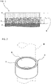
- FIG. 1 is a sectional view of a sliding member, as an example, in the present embodiment.
- a sliding member 1 in the present embodiment contains a metallic substrate 2, a porous layer 3 formed on a surface of the metallic substrate 2, the porous layer being made of a metal itself or an alloy composition, and a sliding layer 5 in which the porous layer 3 is covered with a resin composition 4.
- the porous layer 3 is formed by sintering a metallic powder on a surface of the metallic substrate 2.
- a copper plated steel plate in which copper (Cu) has been plated on an iron (Fe)-based plate is used as the metallic substrate 2.
- Cu copper
- Fe iron
- the metallic powder forming the porous layer 3 Cu itself or an alloy containing Cu as a main component is used, and a Cu-Sn based alloy powder is used in this embodiment.
- the Cu-Sn based alloy powder is sprayed on the copper plated steel plate with a desired thickness thereof and the copper plated steel plate on which the Cu-Sn based alloy powder has been sprayed is sintered in a sintering furnace.
- the porous layer 3 made of a Cu-Sn based alloy with a desired thickness thereof is formed on the copper plated steel plate.
- the porous layer 3 is impregnated with the resin composition 4 so as to have a predetermined thickness thereof and the porous layer 3 that has been impregnated with the resin composition 4 is baked, and then, the sliding layer 5 is formed.
- the resin composition 4 a resin and additives are mixed.
- the resin polytetrafluoroethylene (PTFE) is used as an example of the fluororesin.
- the resin composition 4 contains a pitch-based carbon fiber as an essential additive.
- the resin composition 4 may include any of or a combination of two or more of an aramid fiber, an iron oxide, molybdenum disulfide, a graphite, and zinc, zinc alloy or zinc compound.
- a predetermined amount of the resin composition 4 is supplied onto the porous layer 3 formed on the surface of the metallic substrate 2, and the resin composition 4 is pressed on the porous layer 3, so that the porous layer 3 is impregnated with the resin composition 4.
- the amount of the resin composition 4 supplied onto the porous layer 3 is an amount of the resin composition 4 which covers the porous layer 3 with a thickness such that the porous layer 3 is not exposed from a surface of the sliding layer 5 after the resin composition 4 is baked, which is described later.
- the resin composition 4 When the resin composition 4 is heated at a temperature which exceeds a melting point of a resin contained in the resin composition 4, the resin is melted and an organic solvent is volatilized, and then, the resin is hardened and the sliding layer 5 is formed.
- the term “bake” is referred to as “heating the resin composition 4 at a predetermined temperature to form the sliding layer 5".
- the melting point of polytetrafluoroethylene used as the resin is 327°C.
- the sliding layer 5 is baked using the baking furnace in this embodiment by heating the resin composition 4 at a temperature which exceeds the melting point of polytetrafluoroethylene.
- all of the metallic powders for forming the porous layer 3 may have a particle diameter within a range of about 15 ⁇ m to 180 ⁇ m, preferably about 25 ⁇ m to 150 ⁇ m.
- a thickness T 1 of the porous layer 3 formed by using the metallic powders having such a particle diameter may be set to be about 0.06 mm to 0.35 mm.
- the thickness of the porous layer 3 is a thickness such that at least two pieces of the metallic powders are laid in piles and sintered.
- a thickness T 2 of the sliding layer 5 may be set to be about 0.08 mm to 0.43 mm.
- the thickness T 2 of the sliding layer 5 is referred to as "a thickness of the sliding layer 5 from a surface of the metallic substrate 2".
- the thickness of the sliding layer 5 is set to be averagely larger than the thickness of the porous layer 3 so that the porous layer 3 is not exposed.
- the thickness T 2 of the sliding layer 5 is set to be 0.3 mm.
- FIG. 2 is a perspective view of a bearing, as an example, in the present embodiment
- FIG. 3 is a sectional view of the bearing, as an example, in the present embodiment, in which the sliding member 1 in the present embodiment is used.
- a bearing 7 in the present embodiment is configured such that the sliding member 1 shown in FIG. 1 is annularly formed with the sliding layer 5 being inwardly arranged.
- the bearing 7 supports a rod 8 as a mated member with the sliding layer 5 forming a cylindrical internal circumference.
- the bearing 7 is configured so that the rod 8 is slid under a linear motion.
- the bearing 7 in the present embodiment is used for a vibration damping apparatus such as a shock absorber used for a vehicle or the like and is used as a sliding portion of a guide bushing for guiding a piston rod which reciprocates, in the shock absorber, with a motion of a suspension mechanism that displaces following a variation of a road surface or the like being transferred to the sliding portion.
- a vibration damping apparatus such as a shock absorber used for a vehicle or the like and is used as a sliding portion of a guide bushing for guiding a piston rod which reciprocates, in the shock absorber, with a motion of a suspension mechanism that displaces following a variation of a road surface or the like being transferred to the sliding portion.
- the rod 8 which is a piston rod, is a sliding mated member and the resin composition 4 forming the sliding layer 5 contacts the mated member directly or via a fluid such as oil.
- a surface thereof made of a stainless steel or Fe is configured to be covered with Cr (chromium) or Ti (titanium) by means of a method such as a plating method.
- the mated member of the sliding member 1 may be made of Cr, Ti themselves or their alloy.
- FIG. 4 is a graph showing a relationship between a static friction force and a dynamic friction force.
- a vertical axis indicates a friction force (N) and a horizontal axis indicates a stroke (mm).
- N friction force
- mm stroke
- the piston rod reciprocates based on the fact that the suspension follows the variations of the road surface or the like. Based on the fact that the piston rod reciprocates, there is a state where the piston rod stands still.
- a pitch-based carbon fiber is added to the resin composition 4 forming the sliding layer 5 which contacts the rod 8 as the piston rod and guides the reciprocating motion of the piston rod.
- the resin composition 4 is described in detail.
- the fluororesin which is a base resin of the resin composition 4 is a common synthetic resin having an excellent sliding characteristic to maintain a sufficient heat-resisting property for heat generated when any sliding friction occurs. Therefore, PTFE resins, PFA copolymer resins, FEP copolymer resins, and ETFE copolymer resins are often used as the base resin of the resin composition of the sliding member.
- D-210C or F-201 of POLYFLON (registered trademark) manufactured by Daikin Industries, Ltd; AD911D of Fluon (registered trademark) manufactured by Asahi Glass Co., Ltd; 31JR or 6C-J of Teflon (registered trademark) manufactured by Chemours-Mitsui Fluoro products Co., Ltd and the like are exemplified.
- the pitch-based carbon fiber is an essential additive to the resin composition 4 forming the sliding layer 5 in order to improve the value of the static fiction force and the rate of change in the dynamic friction force in relation to the static friction force.
- the pitch-based carbon fiber is used as a function-imparting material and a reinforcing material for the resin composition 4 forming the sliding layer 5 which contacts the mated member directly or via a fluid such as oil.
- the resin composition 4 contains more than 10 weight% and 35 weight% or less of the pitch-based carbon fiber. It is also preferable that the pitch-based carbon fiber has a fiber diameter of 5 ⁇ m or more and 20 ⁇ m or less, a fiber length of 10 ⁇ m or more and 150 ⁇ m or less, and an aspect ratio of 2 or more and 20 or less.
- the pitch-based carbon fiber has high strength, high modulus, excellent abrasion resistance, a high specific frequency, and an excellent vibration damping and absorbing performance. These characteristics of the pitch-based carbon fiber allow the static friction force to increase and allow the rate of change in the dynamic friction force in relation to the static friction force to be reduced, by containing a predetermined amount of the pitch-based carbon fiber in the resin composition 4. This enables the value of the static friction force and the rate of change in the dynamic friction force in relation to the static friction force to be improved, thereby improving sliding characteristics.
- the rate of change in the dynamic friction force in relation to the static friction force is large and self-abrasion quantity also increases.
- the static friction force is excessive. This may block its dispersiveness and deteriorate impregnation into the porous layer.
- the pitch-based carbon fiber has a fiber length of more than 150 ⁇ m, the impregnation into the porous layer deteriorates and the pitch-based carbon fiber may be left out from the resin composition 4. It is to be noted that as the pitch-based carbon fiber on the market, DONACARBO manufactured by Osaka Gas Chemicals Co., Ltd., DIALEAD manufactured by Mitsubishi Chemical Corporation and the like are exemplified.
- the aramid fiber is not an essential additive for the resin composition 4 forming the sliding layer 5, but a predetermined amount of aramid fibers may be added in the resin composition 4 for improving the value of the static fiction force and the rate of change in the dynamic friction force in relation to the static friction force to improve the sliding characteristics. It is preferable that more than 0 weight% and 14 weight% or less of the aramid fiber is contained when the aramid fiber is added.
- the resin composition 4 allows the abrasion resistance to be enhanced without hindering the value of the static friction force and the rate of change in the dynamic friction force in relation to the static friction force from being improved when the pitch-based carbon fiber is added, allows the value of the static friction force to be made large and allows the rate of change in the dynamic friction force in relation to the static friction force to be reduced.
- Kevlar registered trademark
- Twaron registered trademark
- iron oxide (FeO 2 , Fe 2 O 3 ) is not an essential additive for the resin composition 4 forming the sliding layer 5, but a predetermined amount of iron oxide may be contained in the resin composition 4. It is preferable that more than 0 weight% and 37 weight% or less of the iron oxide is contained when the iron oxide is added.
- the resin composition 4 allows the slidability to be reduced without hindering the value of the static friction force and the rate of change in the dynamic friction force in relation to the static friction force from being improved when the pitch-based carbon fiber is added, allows the value of the static friction force to be made large and allows the rate of change in the dynamic friction force in relation to the static friction force to be reduced.
- molybdenum disulfide (MoS 2 ) is not an essential additive for the resin composition 4 forming the sliding layer 5, but a predetermined amount of molybdenum disulfide may be contained in the resin composition 4. It is preferable that more than 0 weight% and 20 weight% or less of the molybdenum disulfide is contained when the molybdenum disulfide is added.
- the resin composition 4 allows the frictional resistance to be reduced without hindering the value of the static friction force and the rate of change in the dynamic friction force in relation to the static friction force from being improved when the pitch-based carbon fiber is added.
- the graphite (C) is not an essential additive for the resin composition 4 forming the sliding layer 5, but a predetermined amount of graphite may be contained in the resin composition 4. It is preferable that more than 0 weight% and 10 weight% or less of the graphite is contained when the graphite is added.
- the resin composition 4 allows the frictional resistance to be reduced without hindering the value of the static friction force and the rate of change in the dynamic friction force in relation to the static friction force from being improved when the pitch-based carbon fiber is added.
- zinc (Zn), a zinc alloy (Zn alloy), or a zinc compound (Zn compound) is not an essential additive for the resin composition 4 forming the sliding layer 5, but a predetermined amount of the Zn, Zn alloy or Zn compound may be contained in the resin composition 4. It is preferable that more than 0 weight% and 40 weight% or less of the Zn, Zn alloy or Zn compound is contained when the Zn, Zn alloy or Zn compound is added.
- a particle diameter of Zn, Zn alloy or Zn compound is preferably 1 ⁇ m or more and 50 ⁇ m or less, more preferably 1 ⁇ m or more and 25 ⁇ m or less, taking into consideration dispersiveness to the fluororesin and a thickness of the resin layer made of the resin composition.
- the Zn alloy contains 3.5 weight% or more and 4.3 weight% or less of Al, 0.75 weight% or more and 1.25 weight% or less of Cu, 0.020 weight% or more and 0.06 weight% or less of Mg, 0.10 weight% or less of Fe, and the remainder being Zn and inevitable impurities.
- the Zn alloy contains 3.5 weight% or more and 4.3 weight% or less of Al, 0.25 weight% or less of Cu, 0.020 weight% or more and 0.06 weight% or less of Mg, 0.10 weight% or less of Fe, and the remainder being Zn and inevitable impurities.
- the Zn compound include ZnO, ZnS, ZnSO 4 , and the like.
- the resin composition 4 allows the rate of change in the dynamic friction force in relation to the static friction force to be reduced without hindering the value of the static friction force and the rate of change in the dynamic friction force in relation to the static friction force from being improved when the pitch-based carbon fiber is added.
- Adding the Zn, Zn alloy or Zn compound deteriorates the impregnation into the porous layer in the impregnation step when the additive amount of the Zn, Zn alloy or Zn compound exceeds 40 weight%, so that the abrasion resistance deteriorates.
- the guide bushings were prepared using the sliding members having compositions in Examples 1 to 7 and Comparison Examples 1 to 3, as shown in Table 1, and their static friction forces and their rates of change in the dynamic friction force in relation to the static friction force were measured.
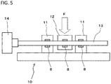
- FIG. 5 shows a configuration example of a testing machine for measuring the static friction force and the dynamic friction force.
- a testing machine 10 guide bushings 8 to be tested were mounted on bearing bases 11 and a load portion 12. Any traverse loads were applied to the load portion 12, via the guide bushing 8, between the bearing bases 11 supporting a rod 13 through the guide bushings 8. A friction force when vibrating the rod 13, to which the traverse load had been applied, by a vibrator (not shown), was measured by a load cell 14.
- Examples 1 to 7 a pitch-based carbon fiber having a fiber diameter of 13 ⁇ m, an average fiber length of 40 ⁇ m and an aspect ratio of 3 was used.
- Comparison Example 2 a pitch-based carbon fiber having a fiber diameter of 14.5 ⁇ m, an average fiber length of 130 ⁇ m, and an aspect ratio of 9 was used.
- Comparison Example 3 the pitch-based carbon fiber which was the same as those in Examples 1 to 7 was used.
- Example 3 It has further been found that, in the resin composition in Example 3 containing 11 weight% of the pitch-based carbon fiber, 14.2 weight% of the zinc alloy, and the remainder being the fluororesin, the static friction force could be made to be a desired one and the rate of change in the dynamic friction force in relation to the static friction force could be reduced.
- the zinc alloy an alloy having the above composition can be selected and used as appropriate.
- Zn-3.89Al-0.05Cu-0.05Mg-0.01Fe was used.
- the static friction force could be made to be a desired one and the rate of change in the dynamic friction force in relation to the static friction force can be reduced.
- the static friction force could be made to be a desired one and the rate of change in the dynamic friction force in relation to the static friction force could be reduced.
- the static friction force can be made large to be a desired one and the rate of change in the dynamic friction force in relation to the static friction force can be reduced. It has been found that taking the value of the static friction force into consideration, more than 10 weight% and 17 weight% or less of the pitch-based carbon fiber is preferably contained and the value of the static friction force can be further improved to a desired one.
- the effect of improving the value of the static friction force and effect of improving the rate of change in the dynamic friction force in relation to the static friction force are not hindered even if the resin composition contains any of or a combination of two or more of an aramid fiber, an iron oxide, molybdenum disulfide, a graphite, and zinc, zinc alloy or zinc compound, and the sliding characteristic is improved.
Landscapes
- Engineering & Computer Science (AREA)
- General Engineering & Computer Science (AREA)
- Mechanical Engineering (AREA)
- Chemical & Material Sciences (AREA)
- Medicinal Chemistry (AREA)
- Chemical Kinetics & Catalysis (AREA)
- Health & Medical Sciences (AREA)
- Polymers & Plastics (AREA)
- Organic Chemistry (AREA)
- Manufacturing & Machinery (AREA)
- Metallurgy (AREA)
- Sliding-Contact Bearings (AREA)
- Fluid-Damping Devices (AREA)
- Compositions Of Macromolecular Compounds (AREA)
Abstract
Description
- The present invention relates to a sliding member slidably supporting a mated member and a bearing using the sliding member.
- A sliding material having a so-called bimetal structure, namely, a two-layer structure in which a Cu-based alloy powder is sintered on a steel plate as a back plate has been often used as a sliding member. In this case, a surface of a metal layer on which the Cu-based alloy powder has been sintered becomes a sliding surface, so that good slidability is ensured by adding lead (Pb) to the Cu-based alloy powder which has been used in the past.
- On the other hand, use of Pb has been limited in various kinds of fields in recent years because of harmful effects to human health and a material without using Pb has been proposed for a sliding member. For example, a sliding member using a resin material is proposed as a sliding material without using Pb (see Patent Literature 1).
- Further, a past sliding member using the resin material has a three-layer structure in which a Cu-based alloy powder is sintered on a steel plate as a back plate so as to be porous and the porous layer is impregnated with a resin composition in which an additive is mixed with a resin, followed by being baked (for example see Patent Literature 2). In this case, a surface of the resin layer is a sliding surface. As the resin composition, taking a heat-resisting property into consideration, a fluororesin such as polytetrafluoroethylene (PTFE) has been generally used. A sliding member impregnated with such PTFE has been used in, for example, a sliding portion of a shock absorber or the like used in a vehicle or the like. In addition, a bearing having a multi-layer structure, which contains a resin composition containing a polytetrafluoroethylene resin, carbon fibers, and a calcium compound, has been proposed (for example, see Patent literature 3). In addition, the following has been proposed: a cylindrical internal circumference is a bearing bush including a porous sintered layer and a resin layer, and a sliding surface of the bearing bush is formed of a fluororesin composition obtained by blending a thermoplastic resin, carbon fibers, and molybdenum disulfide in a fluororesin (for example, see Patent literature 4). In addition, the following has been proposed: the remainder of the sliding member containing the resin composition is made only of fluororesins (for example, see
Patent literatures 5 to 8). -
- Patent Literature 1:
JP S62-127227 A - Patent Literature 2:
JP 2010-159808 A - Patent Literature 3:
JP 2011-137528 A - Patent Literature 4:
JP 2010-159809 A - Patent Literature 5:
JP H05-332365 A - Patent Literature 6:
JP H06-122887 A - Patent Literature 7:
JP 2002-295600 A - Patent Literature 8:
JP 2006-194397 A - In the shock absorber embodied in the vehicle or the like, the sliding member is used in a guide bushing for guiding a piston rod to which a motion of a suspension mechanism that displaces following a variation of a road surface or the like is transferred to make a reciprocating motion.
- The shock absorber damps vibration utilizing viscosity resistance of a liquid therein against any input from outside. On the other hand, it has been found that any friction force generated by the guide bushing which guides the reciprocating motion of the piston rod has an influence on ride quality of a vehicle or the like.
- In other words, a relationship between a static friction force which acts when a static piston rod starts to move and a dynamic friction force which acts when a piston rod moves has an influence on the ride quality of a vehicle or the like. In order to solve the common problem of enhancing the slidability of the sliding member, reducing a dynamic friction coefficient has been common in the past. As described in
Patent Literatures Patent Literature 3 to a resin composition forming a sliding layer of a sliding member. However, in the sliding member in which the sliding layer is impregnated with PTFE, no attempt has been made to increase the static friction force and minimize the rate of change in the dynamic friction force in relation to the static friction force by adjusting the blending of pitch-based carbon fibers and PTFE instead of simply lowering the dynamic friction coefficient. - An object of the present invention is to provide a sliding member that enables the relationship between the static friction force and the dynamic friction force to be controlled, and a bearing using the sliding member.
- The present inventors have found that the static friction force can become large and the relationship between the static friction force and the dynamic friction force can be controlled, by containing a predetermined amount of pitch-based carbon fibers in a resin composition forming a sliding layer.
- The present invention provides a sliding member comprising: a lead-free resin composition, wherein the resin composition contains a pitch-based carbon fiber and a fluororesin, and assuming weight of the resin composition as 100, more than 10 weight% and 35 weight% or less of the pitch-based carbon fiber is contained and the remainder of the resin composition is only the fluororesin.
- In addition, the present invention provides a sliding member comprising: a metallic substrate; a porous layer formed on a surface of the metallic substrate; and a sliding layer that covers the porous layer, wherein the porous layer is made of a metal itself or an alloy composition, wherein the sliding layer is made of a lead-free resin composition, wherein the resin composition contains a pitch-based carbon fiber and a fluororesin, and assuming weight of the resin composition as 100, more than 10 weight% and 35 weight% or less of the pitch-based carbon fiber is contained and the remainder of the resin composition is only the fluororesin.
- It is preferred that the resin composition contains more than 10 weight% and 17 weight% or less of the pitch-based carbon fiber.
- In addition, the present invention provides a sliding member comprising: a lead-free resin composition, wherein assuming weight of the resin composition as 100, the resin composition contains more than 10 weight% and 35 weight% or less of a pitch-based carbon fiber, wherein the resin composition further contains any of or a combination of two or more of an aramid fiber, an iron oxide, molybdenum disulfide, a graphite, and zinc, zinc alloy or zinc compound, more than 0 weight% and 14 weight% or less of the aramid fiber is contained when the aramid fiber is added; more than 0 weight% and 37 weight% or less of the iron oxide is contained when the iron oxide is added; more than 0 weight% and 20 weight% or less of the molybdenum disulfide is contained when the molybdenum disulfide is added; more than 0 weight% and 10 weight% or less of the graphite is contained when the graphite is added; more than 0 weight% and 40 weight% or less of the zinc, zinc alloy or zinc compound is contained when the zinc, zinc alloy or zinc compound is added, and the remainder is a fluororesin.
- In addition, the present invention provides a sliding member comprising: a metallic substrate; a porous layer formed on a surface of the metallic substrate; and a sliding layer that covers the porous layer, wherein the porous layer is made of a metal itself or an alloy composition, wherein the sliding layer is made of a lead-free resin composition, wherein assuming weight of the resin composition as 100, the resin composition contains more than 10 weight% and 35 weight% or less of a pitch-based carbon fiber, wherein the resin composition further contains any of or a combination of two or more of an aramid fiber, an iron oxide, molybdenum disulfide, a graphite, and zinc, zinc alloy or zinc compound, more than 0 weight% and 14 weight% or less of the aramid fiber is contained when the aramid fiber is added; more than 0 weight% and 37 weight% or less of the iron oxide is contained when the iron oxide is added; more than 0 weight% and 20 weight% or less of the molybdenum disulfide is contained when the molybdenum disulfide is added; more than 0 weight% and 10 weight% or less of the graphite is contained when the graphite is added; more than 0 weight% and 40 weight% or less of the zinc, zinc alloy or zinc compound is contained when the zinc, zinc alloy or zinc compound is added, and the remainder is a fluororesin.
- It is preferred that the pitch-based carbon fiber has a fiber diameter of 5 µm or more and 20 µm or less, a fiber length of 10 µm or more and 150 µm or less, and an aspect ratio of 2 or more and 20 or less. In addition, it is preferred that the fluororesin is polytetrafluoroethylene.
- In addition, the present invention provides a bearing comprising: a metallic substrate; a porous layer formed on a surface of the metallic substrate; and a sliding layer that covers the porous layer, the sliding layer being a cylindrical internal circumference and annular innermost layer, wherein the porous layer is made of a metal itself or an alloy composition, wherein the sliding layer is made of a lead-free resin composition, wherein the resin composition contains a pitch-based carbon fiber and a fluororesin, and assuming weight of the resin composition as 100, more than 10 weight% and 35 weight% of the pitch-based carbon fiber is contained and the remainder of the resin composition is only the fluororesin.
- In addition, the present invention provides a bearing comprising: a metallic substrate; a porous layer formed on a surface of the metallic substrate; and a sliding layer that covers the porous layer, the sliding layer being a cylindrical internal circumference and annular innermost layer, wherein the porous layer is made of a metal itself or an alloy composition, wherein the sliding layer is made of a lead-free resin composition, wherein assuming weight of the resin composition as 100, the resin composition contains more than 10 weight% and 35 weight% of a pitch-based carbon fiber, wherein the resin composition further contains any of or a combination of two or more of an aramid fiber, an iron oxide, molybdenum disulfide, a graphite, and zinc, zinc alloy or zinc compound, more than 0 weight% and 14 weight% or less of the aramid fiber is contained when the aramid fiber is added; more than 0 weight% and 37 weight% or less of the iron oxide is contained when the iron oxide is added; more than 0 weight% and 20 weight% or less of the molybdenum disulfide is contained when the molybdenum disulfide is added; more than 0 weight% and 10 weight% or less of the graphite is contained when the graphite is added; more than 0 weight% and 40 weight% or less of the zinc, zinc alloy or zinc compound is contained when the zinc, zinc alloy or zinc compound is added, and the remainder is the fluororesin.
- In the present invention, by adding a predetermined amount of pitch-based carbon fibers, the static friction force can be increased, and the rate of change of the dynamic friction force in relation to the static friction force can be reduced, and further, abrasion can be prevented. Accordingly, when the sliding member of the present invention is applied to a shock absorber, the ride quality can be improved.
-
-
FIG. 1 is a sectional view of a sliding member, as an example, in the present embodiment. -
FIG. 2 is a perspective view of a bearing, as an example, in the present embodiment. -
FIG. 3 is a sectional view of the bearing, as an example, in the present embodiment. -
FIG. 4 is a graph showing a relationship between a static friction force and a dynamic friction force. -
FIG. 5 is a diagram showing a configuration example of a testing machine for measuring the static friction force and the dynamic friction force. - Embodiment of a sliding member of the present invention and embodiment of a bearing to which the sliding member of the present invention is applied are described below with reference to the drawings.
- The sliding member in the present embodiment is formed of a lead-free resin composition. The resin composition contains a fluororesin, and contains a pitch-based carbon fiber as an essential additive. The resin composition contains more than 10 weight% and 35 weight% or less of the pitch-based carbon fiber, and the remainder is the fluororesin. The pitch-based carbon fiber has a fiber diameter of 5 µm or more and 20 µm or less, a fiber length of 10 µm or more and 150 µm or less, and an aspect ratio of 2 or more and 20 or less. The sliding member in the present embodiment is used so as to cover a surface of a metallic substrate and cover a metallic porous layer formed on a surface of the metallic substrate.
-
FIG. 1 is a sectional view of a sliding member, as an example, in the present embodiment. A sliding member 1 in the present embodiment contains ametallic substrate 2, aporous layer 3 formed on a surface of themetallic substrate 2, the porous layer being made of a metal itself or an alloy composition, and asliding layer 5 in which theporous layer 3 is covered with aresin composition 4. - The
porous layer 3 is formed by sintering a metallic powder on a surface of themetallic substrate 2. In this embodiment, a copper plated steel plate in which copper (Cu) has been plated on an iron (Fe)-based plate is used as themetallic substrate 2. As the metallic powder forming theporous layer 3, Cu itself or an alloy containing Cu as a main component is used, and a Cu-Sn based alloy powder is used in this embodiment. - In a manufacturing method of the
porous layer 3, the Cu-Sn based alloy powder is sprayed on the copper plated steel plate with a desired thickness thereof and the copper plated steel plate on which the Cu-Sn based alloy powder has been sprayed is sintered in a sintering furnace. As a result, theporous layer 3 made of a Cu-Sn based alloy with a desired thickness thereof is formed on the copper plated steel plate. - The
porous layer 3 is impregnated with theresin composition 4 so as to have a predetermined thickness thereof and theporous layer 3 that has been impregnated with theresin composition 4 is baked, and then, the slidinglayer 5 is formed. In this embodiment, as theresin composition 4, a resin and additives are mixed. As the resin, polytetrafluoroethylene (PTFE) is used as an example of the fluororesin. - The
resin composition 4 contains a pitch-based carbon fiber as an essential additive. As other optional additives, theresin composition 4 may include any of or a combination of two or more of an aramid fiber, an iron oxide, molybdenum disulfide, a graphite, and zinc, zinc alloy or zinc compound. - In a manufacturing method of the sliding
layer 5, a predetermined amount of theresin composition 4 is supplied onto theporous layer 3 formed on the surface of themetallic substrate 2, and theresin composition 4 is pressed on theporous layer 3, so that theporous layer 3 is impregnated with theresin composition 4. The amount of theresin composition 4 supplied onto theporous layer 3 is an amount of theresin composition 4 which covers theporous layer 3 with a thickness such that theporous layer 3 is not exposed from a surface of the slidinglayer 5 after theresin composition 4 is baked, which is described later. - When the
resin composition 4 is heated at a temperature which exceeds a melting point of a resin contained in theresin composition 4, the resin is melted and an organic solvent is volatilized, and then, the resin is hardened and the slidinglayer 5 is formed. Here, the term "bake" is referred to as "heating theresin composition 4 at a predetermined temperature to form the slidinglayer 5". The melting point of polytetrafluoroethylene used as the resin is 327°C. - The sliding
layer 5 is baked using the baking furnace in this embodiment by heating theresin composition 4 at a temperature which exceeds the melting point of polytetrafluoroethylene. - In the sliding member 1 in this embodiment, all of the metallic powders for forming the
porous layer 3 may have a particle diameter within a range of about 15 µm to 180 µm, preferably about 25 µm to 150 µm. In addition, in the sliding member 1, a thickness T1 of theporous layer 3 formed by using the metallic powders having such a particle diameter may be set to be about 0.06 mm to 0.35 mm. The thickness of theporous layer 3 is a thickness such that at least two pieces of the metallic powders are laid in piles and sintered. - Further, in the sliding member 1, a thickness T2 of the sliding
layer 5 may be set to be about 0.08 mm to 0.43 mm. Here, the thickness T2 of the slidinglayer 5 is referred to as "a thickness of the slidinglayer 5 from a surface of themetallic substrate 2". The thickness of the slidinglayer 5 is set to be averagely larger than the thickness of theporous layer 3 so that theporous layer 3 is not exposed. In this embodiment, the thickness T2 of the slidinglayer 5 is set to be 0.3 mm. -
FIG. 2 is a perspective view of a bearing, as an example, in the present embodiment, andFIG. 3 is a sectional view of the bearing, as an example, in the present embodiment, in which the sliding member 1 in the present embodiment is used. - A
bearing 7 in the present embodiment is configured such that the sliding member 1 shown inFIG. 1 is annularly formed with the slidinglayer 5 being inwardly arranged. Thebearing 7 supports arod 8 as a mated member with the slidinglayer 5 forming a cylindrical internal circumference. Thebearing 7 is configured so that therod 8 is slid under a linear motion. - The
bearing 7 in the present embodiment is used for a vibration damping apparatus such as a shock absorber used for a vehicle or the like and is used as a sliding portion of a guide bushing for guiding a piston rod which reciprocates, in the shock absorber, with a motion of a suspension mechanism that displaces following a variation of a road surface or the like being transferred to the sliding portion. - In the sliding member 1, the
rod 8, which is a piston rod, is a sliding mated member and theresin composition 4 forming the slidinglayer 5 contacts the mated member directly or via a fluid such as oil. In the mated member of the sliding member 1, a surface thereof made of a stainless steel or Fe is configured to be covered with Cr (chromium) or Ti (titanium) by means of a method such as a plating method. The mated member of the sliding member 1 may be made of Cr, Ti themselves or their alloy. -
FIG. 4 is a graph showing a relationship between a static friction force and a dynamic friction force. InFIG. 4 , a vertical axis indicates a friction force (N) and a horizontal axis indicates a stroke (mm). In the shock absorber used for a vehicle or the like, the piston rod reciprocates based on the fact that the suspension follows the variations of the road surface or the like. Based on the fact that the piston rod reciprocates, there is a state where the piston rod stands still. - Accordingly, in the guide bushing used for the shock absorber, in the case where the rate of change in a dynamic friction force Fm2 in relation to a static friction force Fs2 is large, as shown in broken lines of
FIG. 4 , it is felt uncomfortable to ride in the vehicle or the like. In the case where the static friction force Fs2 is small, it is also felt uncomfortable to ride in the vehicle or the like. In the case where the static friction force Fs2 is large and the rate of change in the dynamic friction force Fm2 in relation to the static friction force Fs2 is small, the ride quality of the vehicles or the like is improved. - Therefore, in the sliding member 1 used as the
bearing 7 constituting the guide bushing, a pitch-based carbon fiber is added to theresin composition 4 forming the slidinglayer 5 which contacts therod 8 as the piston rod and guides the reciprocating motion of the piston rod. Hereinafter, theresin composition 4 is described in detail. - The fluororesin which is a base resin of the
resin composition 4 is a common synthetic resin having an excellent sliding characteristic to maintain a sufficient heat-resisting property for heat generated when any sliding friction occurs. Therefore, PTFE resins, PFA copolymer resins, FEP copolymer resins, and ETFE copolymer resins are often used as the base resin of the resin composition of the sliding member. - As the PTFE resin on the market, D-210C or F-201 of POLYFLON (registered trademark) manufactured by Daikin Industries, Ltd; AD911D of Fluon (registered trademark) manufactured by Asahi Glass Co., Ltd; 31JR or 6C-J of Teflon (registered trademark) manufactured by Chemours-Mitsui Fluoro products Co., Ltd and the like are exemplified.
- The pitch-based carbon fiber (CF) is an essential additive to the
resin composition 4 forming the slidinglayer 5 in order to improve the value of the static fiction force and the rate of change in the dynamic friction force in relation to the static friction force. The pitch-based carbon fiber is used as a function-imparting material and a reinforcing material for theresin composition 4 forming the slidinglayer 5 which contacts the mated member directly or via a fluid such as oil. - It is preferable that the
resin composition 4 contains more than 10 weight% and 35 weight% or less of the pitch-based carbon fiber. It is also preferable that the pitch-based carbon fiber has a fiber diameter of 5 µm or more and 20 µm or less, a fiber length of 10 µm or more and 150 µm or less, and an aspect ratio of 2 or more and 20 or less. - The pitch-based carbon fiber has high strength, high modulus, excellent abrasion resistance, a high specific frequency, and an excellent vibration damping and absorbing performance. These characteristics of the pitch-based carbon fiber allow the static friction force to increase and allow the rate of change in the dynamic friction force in relation to the static friction force to be reduced, by containing a predetermined amount of the pitch-based carbon fiber in the
resin composition 4. This enables the value of the static friction force and the rate of change in the dynamic friction force in relation to the static friction force to be improved, thereby improving sliding characteristics. - In the case where 10 weight% or less of the pitch-based carbon fiber is added, the rate of change in the dynamic friction force in relation to the static friction force is large and self-abrasion quantity also increases. In the case where more than 35 weight% of the pitch-based carbon fiber is added, the static friction force is excessive. This may block its dispersiveness and deteriorate impregnation into the porous layer. Further, in the case where the pitch-based carbon fiber has a fiber length of more than 150 µm, the impregnation into the porous layer deteriorates and the pitch-based carbon fiber may be left out from the
resin composition 4. It is to be noted that as the pitch-based carbon fiber on the market, DONACARBO manufactured by Osaka Gas Chemicals Co., Ltd., DIALEAD manufactured by Mitsubishi Chemical Corporation and the like are exemplified. - In the present invention, the aramid fiber is not an essential additive for the
resin composition 4 forming the slidinglayer 5, but a predetermined amount of aramid fibers may be added in theresin composition 4 for improving the value of the static fiction force and the rate of change in the dynamic friction force in relation to the static friction force to improve the sliding characteristics. It is preferable that more than 0 weight% and 14 weight% or less of the aramid fiber is contained when the aramid fiber is added. - By adding the predetermined amount of aramid fibers to the
resin composition 4, theresin composition 4 allows the abrasion resistance to be enhanced without hindering the value of the static friction force and the rate of change in the dynamic friction force in relation to the static friction force from being improved when the pitch-based carbon fiber is added, allows the value of the static friction force to be made large and allows the rate of change in the dynamic friction force in relation to the static friction force to be reduced. - Adding the aramid fiber hinders homogeneous dispersion when the additive amount of the aramid fiber exceeds 14 weight%, so that the abrasion resistance deteriorates. It is to be noted that as the aramid fiber on the market, Kevlar (registered trademark) manufactured by DU PONT-TORAY CO., LTD., Twaron (registered trademark) manufactured by TEIJIN LIMITED and the like are exemplified.
- In the present invention, iron oxide (FeO2, Fe2O3) is not an essential additive for the
resin composition 4 forming the slidinglayer 5, but a predetermined amount of iron oxide may be contained in theresin composition 4. It is preferable that more than 0 weight% and 37 weight% or less of the iron oxide is contained when the iron oxide is added. - By adding the predetermined amount of iron oxide to the
resin composition 4, theresin composition 4 allows the slidability to be reduced without hindering the value of the static friction force and the rate of change in the dynamic friction force in relation to the static friction force from being improved when the pitch-based carbon fiber is added, allows the value of the static friction force to be made large and allows the rate of change in the dynamic friction force in relation to the static friction force to be reduced. - Adding the iron oxide deteriorates the impregnation into the porous layer in the impregnation step when the additive amount of the iron oxide exceeds 37 weight%. It is to be noted that as the iron oxide on the market, Bengara Color Series manufactured by MORISHITA BENGARA KOUGYO CO., LTD. and the like are exemplified.
- In the present invention, molybdenum disulfide (MoS2) is not an essential additive for the
resin composition 4 forming the slidinglayer 5, but a predetermined amount of molybdenum disulfide may be contained in theresin composition 4. It is preferable that more than 0 weight% and 20 weight% or less of the molybdenum disulfide is contained when the molybdenum disulfide is added. - By adding the predetermined amount of the molybdenum disulfide to the
resin composition 4, theresin composition 4 allows the frictional resistance to be reduced without hindering the value of the static friction force and the rate of change in the dynamic friction force in relation to the static friction force from being improved when the pitch-based carbon fiber is added. - Adding the molybdenum disulfide deteriorates the impregnation into the porous layer in the impregnation step when the additive amount of the molybdenum disulfide exceeds 20 weight%. It is to be noted that as the molybdenum disulfide on the market, H/GMoS2 manufactured by TAIYO KOKO Co., Ltd., Molybdenum Disulfide Powder Series manufactured by DAIZO CORPORATION and the like are exemplified.
- In the present invention, the graphite (C) is not an essential additive for the
resin composition 4 forming the slidinglayer 5, but a predetermined amount of graphite may be contained in theresin composition 4. It is preferable that more than 0 weight% and 10 weight% or less of the graphite is contained when the graphite is added. - By adding the predetermined amount of the graphite to the
resin composition 4, theresin composition 4 allows the frictional resistance to be reduced without hindering the value of the static friction force and the rate of change in the dynamic friction force in relation to the static friction force from being improved when the pitch-based carbon fiber is added. - Adding the graphite deteriorates the impregnation into the porous layer in the impregnation step when the additive amount of the graphite exceeds 10 weight%. It is to be noted that as the graphite on the market, GRAPHITE POWDER SERIES manufactured by Nippon Kokuen Group and the like are exemplified.
- In the present invention, zinc (Zn), a zinc alloy (Zn alloy), or a zinc compound (Zn compound) is not an essential additive for the
resin composition 4 forming the slidinglayer 5, but a predetermined amount of the Zn, Zn alloy or Zn compound may be contained in theresin composition 4. It is preferable that more than 0 weight% and 40 weight% or less of the Zn, Zn alloy or Zn compound is contained when the Zn, Zn alloy or Zn compound is added. A particle diameter of Zn, Zn alloy or Zn compound is preferably 1 µm or more and 50 µm or less, more preferably 1 µm or more and 25 µm or less, taking into consideration dispersiveness to the fluororesin and a thickness of the resin layer made of the resin composition. - Assuming weight of the Zn alloy as 100, the Zn alloy contains 3.5 weight% or more and 4.3 weight% or less of Al, 0.75 weight% or more and 1.25 weight% or less of Cu, 0.020 weight% or more and 0.06 weight% or less of Mg, 0.10 weight% or less of Fe, and the remainder being Zn and inevitable impurities.
- Alternatively, assuming weight of the Zn alloy as 100, the Zn alloy contains 3.5 weight% or more and 4.3 weight% or less of Al, 0.25 weight% or less of Cu, 0.020 weight% or more and 0.06 weight% or less of Mg, 0.10 weight% or less of Fe, and the remainder being Zn and inevitable impurities. Examples of the Zn compound include ZnO, ZnS, ZnSO4, and the like.
- By adding the predetermined amount of Zn, Zn alloy or Zn compound to the
resin composition 4, theresin composition 4 allows the rate of change in the dynamic friction force in relation to the static friction force to be reduced without hindering the value of the static friction force and the rate of change in the dynamic friction force in relation to the static friction force from being improved when the pitch-based carbon fiber is added. - Adding the Zn, Zn alloy or Zn compound deteriorates the impregnation into the porous layer in the impregnation step when the additive amount of the Zn, Zn alloy or Zn compound exceeds 40 weight%, so that the abrasion resistance deteriorates.
- The guide bushings were prepared using the sliding members having compositions in Examples 1 to 7 and Comparison Examples 1 to 3, as shown in Table 1, and their static friction forces and their rates of change in the dynamic friction force in relation to the static friction force were measured.
-
FIG. 5 shows a configuration example of a testing machine for measuring the static friction force and the dynamic friction force. In atesting machine 10,guide bushings 8 to be tested were mounted on bearingbases 11 and aload portion 12. Any traverse loads were applied to theload portion 12, via theguide bushing 8, between the bearingbases 11 supporting arod 13 through theguide bushings 8. A friction force when vibrating therod 13, to which the traverse load had been applied, by a vibrator (not shown), was measured by aload cell 14. - In Examples 1 to 7, a pitch-based carbon fiber having a fiber diameter of 13 µm, an average fiber length of 40 µm and an aspect ratio of 3 was used. As the pitch-based carbon fiber used in Examples 1 to 7, for example, DONACARBO S-2404N manufactured by Osaka Gas Chemicals Co., Ltd. was exemplified. In Comparison Example 2, a pitch-based carbon fiber having a fiber diameter of 14.5 µm, an average fiber length of 130 µm, and an aspect ratio of 9 was used. In Comparison Example 3, the pitch-based carbon fiber which was the same as those in Examples 1 to 7 was used.
-
- Mated member: S45C + hard chromium plating, surface roughness Rz of 0.3 µm
- Vibrator: 0.001 m/sec (stroke of 5 mm)
- Traverse load: 98N (10 kgf), 196N (20 kgf) and 294N (30 kgf)
- Lubricating oil: oil for shock absorber
-
- (1) Static Friction Force
- A: The static friction force that is 51 N or more and less than 115 N when the load was 294 N.
- B: The static friction force that is 115 N or more and 120 N or less when the load was 294 N.
- C: The static friction force that is 45 N or more and less than 51 N when the load was 294 N.
- D: The static friction force that is less than 45 N or more than 120 N when the load was 294 N.
- (2) Rte of Change in Dynamic Friction Force in relation to Static Friction Force
- A: 16% or less
- B: more than 16% and 17% or less
- C: more than 17%
- As shown in Table 1, in each of Examples in which the pitch-based carbon fiber having a fiber diameter of 13 µm, an average fiber length of 40 µm and an aspect ratio of 3 was used, it has been found that, in the resin composition in Example 1 containing 11 weight% of the pitch-based carbon fiber, and the remainder being the fluororesin (PTFE), the static friction force could be made large to be a desired one and the rate of change in the dynamic friction force in relation to the static friction force could be reduced.
- It has also been found that, in the resin composition in Example 2 containing 11.4 weight% of the pitch-based carbon fiber, 11 weight% of the iron oxide, and the remainder being the fluororesin, the static friction force could be made to be a desired one and the rate of change in the dynamic friction force in relation to the static friction force could be reduced.
- It has further been found that, in the resin composition in Example 3 containing 11 weight% of the pitch-based carbon fiber, 14.2 weight% of the zinc alloy, and the remainder being the fluororesin, the static friction force could be made to be a desired one and the rate of change in the dynamic friction force in relation to the static friction force could be reduced. As the zinc alloy, an alloy having the above composition can be selected and used as appropriate. In this Example 3, Zn-3.89Al-0.05Cu-0.05Mg-0.01Fe was used.
- It has additionally been found that, in the resin composition in Example 4 containing 11 weight% of the pitch-based carbon fiber, 5 weight% of the iron oxide, 1.6 weight% of the aramid fiber, 1.7 weight% of the graphite, and the remainder being the fluororesin, the static friction force could be made to be a desired one and the rate of change in the dynamic friction force in relation to the static friction force can be reduced.
- It has still further been found that, in the resin composition in Example 5 containing 11 weight% of the pitch-based carbon fiber, 5 weight% of the iron oxide, 1.7 weight% of the aramid fiber, 3.7 weight% of the molybdenum disulfide, and the remainder being the fluororesin, the static friction force could be made to be a desired one and the rate of change in the dynamic friction force in relation to the static friction force could be reduced.
- It has also been found that, in the resin composition in Example 6 containing 16.4 weight% of the pitch-based carbon fiber, and the remainder being the fluororesin, the static friction force could be made to be a desired one and the rate of change in the dynamic friction force in relation to the static friction force could be reduced.
- It has also been found that, in the resin composition in Example 7 containing 35 weight% of the pitch-based carbon fiber, and the remainder being the fluororesin, the static friction force could be made to be a desired one and the rate of change in the dynamic friction force in relation to the static friction force could be reduced. In all of Examples 1 to 7, any self-abrasion of the sliding member and any abrasion of the mated member were controlled.
- In contrast, it has been found that, in the resin composition in Comparison Example 1 containing 100 weight% of the fluororesin, the static friction force could not be made large to be a desired one and the rate of change in the dynamic friction force in relation to the static friction force increased.
- It has been found that, in the resin composition in Comparison Example 2 containing 10 weight% of the pitch-based carbon fiber having a fiber diameter of 14.5 µm, an average fiber length of 130 µm, and an aspect ratio of 9, and the remainder being the fluororesin, the static friction force was large and the rate of change in the dynamic friction force in relation to the static friction force had a tendency to reduce, as compared with the case of the resin composition containing no pitch-based carbon fibers, but the value of the static friction force and the rate of change in the dynamic friction force in relation to the static friction force could not be set to a desired value. In the case where the resin composition contains 10 weight% of the pitch-based carbon fiber, the self-abrasion is made excessive. In Comparison Example 2, the value of the static friction force and the rate of change in the dynamic friction force in relation to the static friction force could not be set to a desired value even if the pitch-based carbon fiber was the same as those used in Examples 1 to 7.
- It has also been found that, in the resin composition in Comparison Example 3 containing 36 weight% of the pitch-based carbon fiber having a fiber diameter of 13 µm, an average fiber length of 40 µm, and an aspect ratio of 3, and the remainder being the fluororesin, the static friction force was excessive.
- In a case of PAN-based carbon fibers, the rate of change in the dynamic friction force in relation to the static friction force had a tendency to reduce but the value of the static friction force could not be a desired one.
- Accordingly, it has been found that, by containing more than 10 weight% and 35 weight% or less of a pitch-based carbon fiber having a fiber diameter of 5 µm or more and 20 µm or less, a fiber length of 10 µm or more and 150 µm or less and an aspect ratio of 2 or more and 20 or less, the static friction force can be made large to be a desired one and the rate of change in the dynamic friction force in relation to the static friction force can be reduced. It has been found that taking the value of the static friction force into consideration, more than 10 weight% and 17 weight% or less of the pitch-based carbon fiber is preferably contained and the value of the static friction force can be further improved to a desired one.
- It has been found that the effect of improving the value of the static friction force and effect of improving the rate of change in the dynamic friction force in relation to the static friction force, the effects being obtained by containing the pitch-based carbon fiber within a scope of the present invention, are not hindered even if the resin composition contains any of or a combination of two or more of an aramid fiber, an iron oxide, molybdenum disulfide, a graphite, and zinc, zinc alloy or zinc compound, and the sliding characteristic is improved.
-
- 1:
- Sliding member
- 10:
- Bearing
- 2:
- Metallic substrate
- 3:
- Porous layer
- 4:
- Resin composition
- 5:
- Sliding layer
- 7:
- Bearing
| Example 1 | Example 2 | Example 3 | Example 4 | Example 5 | Example 6 | Example 7 | Comparative Example 1 | Comparative Example 2 | Comparative Example 3 | |
| Fluororesin (wt%) | Balance | Balance | Balance | Balance | Balance | Balance | Balance | 100 | Balance | Balance |
| Pitch-based carbon fiber (wt%) | 11 | 11.4 | 11 | 11 | 11 | 16.4 | 35 | - | 10 | 36 |
| Aramid fiber (wt%) | - | - | - | 1.6 | 1.7 | - | - | - | - | - |
| Iron oxide (wt%) | - | 11 | - | 5 | 5 | - | - | - | - | - |
| Molybdenum disulfide (wt%) | - | - | - | - | 3.7 | - | - | - | - | - |
| Graphite (wt%) | - | - | - | 1.7 | - | - | - | - | - | - |
| Zinc or zinc alloy (wt%) | - | - | 14.2 | - | - | - | - | - | - | - |
| Static friction force | A | A | A | A | A | A | B | D | C | D |
| Rate of change | A | A | A | A | A | A | A | C | B | A |
Claims (9)
- A sliding member comprising:a lead-free resin composition,wherein the resin composition contains a pitch-based carbon fiber and a fluororesin, and assuming weight of the resin composition as 100, more than 10 weight% and 35 weight% or less of the pitch-based carbon fiber is contained and the remainder of the resin composition is only the fluororesin.
- A sliding member comprising:a metallic substrate;a porous layer formed on a surface of the metallic substrate; anda sliding layer that covers the porous layer,wherein the porous layer is made of a metal itself or an alloy composition,wherein the sliding layer is made of a lead-free resin composition,wherein the resin composition contains a pitch-based carbon fiber and a fluororesin, and assuming weight of the resin composition as 100, more than 10 weight% and 35 weight% or less of the pitch-based carbon fiber is contained and the remainder of the resin composition is only the fluororesin.
- The sliding member according to claim 1 or 2,
wherein the resin composition contains more than 10 weight% and 17 weight% or less of the pitch-based carbon fiber. - A sliding member comprising:a lead-free resin composition,wherein assuming weight of the resin composition as 100, the resin composition contains more than 10 weight% and 35 weight% or less of a pitch-based carbon fiber,wherein the resin composition further contains any of or a combination of two or more of an aramid fiber, an iron oxide, molybdenum disulfide, a graphite, and a zinc alloy or zinc compound,more than 0 weight% and 14 weight% or less of the aramid fiber is contained when the aramid fiber is added;more than 0 weight% and 37 weight% or less of the iron oxide is contained when the iron oxide is added;more than 0 weight% and 20 weight% or less of the molybdenum disulfide is contained when the molybdenum disulfide is added;more than 0 weight% and 10 weight% or less of the graphite is contained when the graphite is added;more than 0 weight% and 40 weight% or less of the zinc, zinc alloy or zinc compound is contained when the zinc, zinc alloy or zinc compound is added, and the remainder is a fluororesin.
- A sliding member comprising:a metallic substrate;a porous layer formed on a surface of the metallic substrate; anda sliding layer that covers the porous layer,wherein the porous layer is made of a metal itself or an alloy composition,wherein the sliding layer is made of a lead-free resin composition,wherein assuming weight of the resin composition as 100, the resin composition contains more than 10 weight% and 35 weight% or less of a pitch-based carbon fiber,wherein the resin composition further contains any of or a combination of two or more of an aramid fiber, an iron oxide, molybdenum disulfide, a graphite, and zinc, zinc alloy or zinc compound,more than 0 weight% and 14 weight% or less of the aramid fiber is contained when the aramid fiber is added;more than 0 weight% and 37 weight% or less of the iron oxide is contained when the iron oxide is added;more than 0 weight% and 20 weight% or less of the molybdenum disulfide is contained when the molybdenum disulfide is added;more than 0 weight% and 10 weight% or less of the graphite is contained when the graphite is added;more than 0 weight% and 40 weight% or less of the zinc, zinc alloy or zinc compound is contained when the zinc, zinc alloy or zinc compound is added, and the remainder is a fluororesin.
- The sliding member according to any one of the claims 1 to 5,
wherein the pitch-based carbon fiber has a fiber diameter of 5 µm or more and 20 µm or less, a fiber length of 10 µm or more and 150 µm or less, and an aspect ratio of 2 or more and 20 or less. - The sliding member according to any one of the claims 1 to 5,
wherein the fluororesin is polytetrafluoroethylene. - A bearing comprising:a metallic substrate;a porous layer formed on a surface of the metallic substrate; anda sliding layer that covers the porous layer, the sliding layer being a cylindrical internal circumference and annular innermost layer,wherein the porous layer is made of a metal itself or an alloy composition,wherein the sliding layer is made of a lead-free resin composition,wherein the resin composition contains a pitch-based carbon fiber and a fluororesin, and assuming weight of the resin composition as 100, more than 10 weight% and 35 weight% of the pitch-based carbon fiber is contained and the remainder of the resin composition is only the fluororesin.
- A bearing comprising:a metallic substrate;a porous layer formed on a surface of the metallic substrate; anda sliding layer that covers the porous layer, the sliding layer being a cylindrical internal circumference and annular innermost layer,wherein the porous layer is made of a metal itself or an alloy composition,wherein the sliding layer is made of a lead-free resin composition,wherein assuming weight of the resin composition as 100, the resin composition contains more than 10 weight% and 35 weight% of a pitch-based carbon fiber,wherein the resin composition further contains any of or a combination of two or more of an aramid fiber, an iron oxide, molybdenum disulfide, a graphite, and zinc, zinc alloy or zinc compound,more than 0 weight% and 14 weight% or less of the aramid fiber is contained when the aramid fiber is added;more than 0 weight% and 37 weight% or less of the iron oxide is contained when the iron oxide is added;more than 0 weight% and 20 weight% or less of the molybdenum disulfide is contained when the molybdenum disulfide is added;more than 0 weight% and 10 weight% or less of the graphite is contained when the graphite is added;more than 0 weight% and 40 weight% or less of the zinc, zinc alloy or zinc compound is contained when the zinc, zinc alloy or zinc compound is added, and the remainder is a fluororesin.
Applications Claiming Priority (3)
| Application Number | Priority Date | Filing Date | Title |
|---|---|---|---|
| JP2017241146 | 2017-12-15 | ||
| JP2018232479A JP6551595B2 (en) | 2017-12-15 | 2018-12-12 | Sliding member and bearing |
| PCT/JP2018/045857 WO2019117244A1 (en) | 2017-12-15 | 2018-12-13 | Sliding member and bearing |
Publications (3)
| Publication Number | Publication Date |
|---|---|
| EP3726080A1 true EP3726080A1 (en) | 2020-10-21 |
| EP3726080A4 EP3726080A4 (en) | 2021-09-15 |
| EP3726080B1 EP3726080B1 (en) | 2024-09-11 |
Family
ID=67179397
Family Applications (1)
| Application Number | Title | Priority Date | Filing Date |
|---|---|---|---|
| EP18888609.7A Active EP3726080B1 (en) | 2017-12-15 | 2018-12-13 | Sliding member and bearing |
Country Status (2)
| Country | Link |
|---|---|
| EP (1) | EP3726080B1 (en) |
| JP (1) | JP6551595B2 (en) |
Families Citing this family (1)
| Publication number | Priority date | Publication date | Assignee | Title |
|---|---|---|---|---|
| JP2023153091A (en) * | 2022-03-31 | 2023-10-17 | 大阪ガスケミカル株式会社 | resin composition |
Family Cites Families (9)
| Publication number | Priority date | Publication date | Assignee | Title |
|---|---|---|---|---|
| JPH05332365A (en) * | 1992-05-25 | 1993-12-14 | Senju Metal Ind Co Ltd | Dry bearing and manufacture thereof |
| JP2568793B2 (en) * | 1992-10-12 | 1997-01-08 | 大同メタル工業株式会社 | Composite sliding member |
| JP2002295600A (en) * | 2001-03-29 | 2002-10-09 | Ntn Corp | Chain bush, connection pin for chain, and chain |
| JP5076276B2 (en) * | 2005-01-17 | 2012-11-21 | オイレス工業株式会社 | Multi-layer sliding member |
| JP5514445B2 (en) * | 2009-01-07 | 2014-06-04 | Ntn株式会社 | Bearing bush for seat reclining device and seat reclining device |
| JP5342883B2 (en) * | 2009-01-07 | 2013-11-13 | Ntn株式会社 | Double layer bearing |
| JP2011137528A (en) * | 2009-12-29 | 2011-07-14 | Ntn Corp | Multilayer bearing |
| US20150147012A1 (en) * | 2013-11-27 | 2015-05-28 | Emerson Climate Technologies, Inc. | Bearing performance for compressors using high energy refrigerants with sulfur-based oil additives |
| JP6323607B1 (en) * | 2017-12-15 | 2018-05-16 | 千住金属工業株式会社 | Sliding member and bearing |
-
2018
- 2018-12-12 JP JP2018232479A patent/JP6551595B2/en active Active
- 2018-12-13 EP EP18888609.7A patent/EP3726080B1/en active Active
Also Published As
| Publication number | Publication date |
|---|---|
| JP2019108980A (en) | 2019-07-04 |
| EP3726080A4 (en) | 2021-09-15 |
| EP3726080B1 (en) | 2024-09-11 |
| JP6551595B2 (en) | 2019-07-31 |
Similar Documents
| Publication | Publication Date | Title |
|---|---|---|
| EP3499060A1 (en) | Sliding member and bearing | |
| US11261914B2 (en) | Sliding member and bearing | |
| CN102272469B (en) | Multi-layer bearing | |
| KR101487120B1 (en) | Sliding member and bearing | |
| JP3635096B2 (en) | Plain bearing material | |
| EP3751162B1 (en) | Sliding member and bearing | |
| KR100583031B1 (en) | Overlay Materials and Multilayer Composite Materials | |
| US20160319867A1 (en) | Plain bearing material and a plain bearing composite material, comprising zinc sulphide and barium sulphate | |
| KR101533458B1 (en) | Sliding bearing with improved wear resistance and method of manufacturing the same | |
| US8128168B2 (en) | Bearing bush for seat reclining device and seat reclining device | |
| KR100499537B1 (en) | Composite bearings containing iron oxide additives | |
| KR101520129B1 (en) | Metal-backed plain bearing | |
| EP1839846A1 (en) | Multilayer sliding member | |
| JPH058219B2 (en) | ||
| CN107001630A (en) | Plain bearing elements | |
| JP6256569B1 (en) | Sliding member and bearing | |
| EP3726080B1 (en) | Sliding member and bearing | |
| US12612944B2 (en) | Sliding member and bearing | |
| US20250198461A1 (en) | Sliding member and bearing |
Legal Events
| Date | Code | Title | Description |
|---|---|---|---|
| STAA | Information on the status of an ep patent application or granted ep patent |
Free format text: STATUS: THE INTERNATIONAL PUBLICATION HAS BEEN MADE |
|
| PUAI | Public reference made under article 153(3) epc to a published international application that has entered the european phase |
Free format text: ORIGINAL CODE: 0009012 |
|
| STAA | Information on the status of an ep patent application or granted ep patent |
Free format text: STATUS: REQUEST FOR EXAMINATION WAS MADE |
|
| 17P | Request for examination filed |
Effective date: 20200615 |
|
| AK | Designated contracting states |
Kind code of ref document: A1 Designated state(s): AL AT BE BG CH CY CZ DE DK EE ES FI FR GB GR HR HU IE IS IT LI LT LU LV MC MK MT NL NO PL PT RO RS SE SI SK SM TR |
|
| AX | Request for extension of the european patent |
Extension state: BA ME |
|
| DAV | Request for validation of the european patent (deleted) | ||
| DAX | Request for extension of the european patent (deleted) | ||
| A4 | Supplementary search report drawn up and despatched |
Effective date: 20210817 |
|
| RIC1 | Information provided on ipc code assigned before grant |
Ipc: F16F 9/32 20060101ALI20210811BHEP Ipc: F16C 33/14 20060101ALI20210811BHEP Ipc: F16C 33/12 20060101ALI20210811BHEP Ipc: F16C 17/02 20060101ALI20210811BHEP Ipc: C08L 27/12 20060101ALI20210811BHEP Ipc: C08K 7/02 20060101ALI20210811BHEP Ipc: C08K 3/00 20180101ALI20210811BHEP Ipc: F16C 33/20 20060101AFI20210811BHEP |
|
| GRAP | Despatch of communication of intention to grant a patent |
Free format text: ORIGINAL CODE: EPIDOSNIGR1 |
|
| STAA | Information on the status of an ep patent application or granted ep patent |
Free format text: STATUS: GRANT OF PATENT IS INTENDED |
|
| INTG | Intention to grant announced |
Effective date: 20240419 |
|
| GRAS | Grant fee paid |
Free format text: ORIGINAL CODE: EPIDOSNIGR3 |
|
| GRAA | (expected) grant |
Free format text: ORIGINAL CODE: 0009210 |
|
| STAA | Information on the status of an ep patent application or granted ep patent |
Free format text: STATUS: THE PATENT HAS BEEN GRANTED |
|
| AK | Designated contracting states |
Kind code of ref document: B1 Designated state(s): AL AT BE BG CH CY CZ DE DK EE ES FI FR GB GR HR HU IE IS IT LI LT LU LV MC MK MT NL NO PL PT RO RS SE SI SK SM TR |
|
| REG | Reference to a national code |
Ref country code: GB Ref legal event code: FG4D |
|
| REG | Reference to a national code |
Ref country code: CH Ref legal event code: EP |
|
| REG | Reference to a national code |
Ref country code: DE Ref legal event code: R096 Ref document number: 602018074389 Country of ref document: DE |
|
| REG | Reference to a national code |
Ref country code: IE Ref legal event code: FG4D |
|
| REG | Reference to a national code |
Ref country code: LT Ref legal event code: MG9D |
|
| PG25 | Lapsed in a contracting state [announced via postgrant information from national office to epo] |
Ref country code: NO Free format text: LAPSE BECAUSE OF FAILURE TO SUBMIT A TRANSLATION OF THE DESCRIPTION OR TO PAY THE FEE WITHIN THE PRESCRIBED TIME-LIMIT Effective date: 20241211 |
|
| REG | Reference to a national code |
Ref country code: NL Ref legal event code: MP Effective date: 20240911 |
|
| PG25 | Lapsed in a contracting state [announced via postgrant information from national office to epo] |
Ref country code: FI Free format text: LAPSE BECAUSE OF FAILURE TO SUBMIT A TRANSLATION OF THE DESCRIPTION OR TO PAY THE FEE WITHIN THE PRESCRIBED TIME-LIMIT Effective date: 20240911 Ref country code: GR Free format text: LAPSE BECAUSE OF FAILURE TO SUBMIT A TRANSLATION OF THE DESCRIPTION OR TO PAY THE FEE WITHIN THE PRESCRIBED TIME-LIMIT Effective date: 20241212 |
|
| PG25 | Lapsed in a contracting state [announced via postgrant information from national office to epo] |
Ref country code: BG Free format text: LAPSE BECAUSE OF FAILURE TO SUBMIT A TRANSLATION OF THE DESCRIPTION OR TO PAY THE FEE WITHIN THE PRESCRIBED TIME-LIMIT Effective date: 20240911 |
|
| PG25 | Lapsed in a contracting state [announced via postgrant information from national office to epo] |
Ref country code: LV Free format text: LAPSE BECAUSE OF FAILURE TO SUBMIT A TRANSLATION OF THE DESCRIPTION OR TO PAY THE FEE WITHIN THE PRESCRIBED TIME-LIMIT Effective date: 20240911 |
|
| PG25 | Lapsed in a contracting state [announced via postgrant information from national office to epo] |
Ref country code: HR Free format text: LAPSE BECAUSE OF FAILURE TO SUBMIT A TRANSLATION OF THE DESCRIPTION OR TO PAY THE FEE WITHIN THE PRESCRIBED TIME-LIMIT Effective date: 20240911 |
|
| PG25 | Lapsed in a contracting state [announced via postgrant information from national office to epo] |
Ref country code: RS Free format text: LAPSE BECAUSE OF FAILURE TO SUBMIT A TRANSLATION OF THE DESCRIPTION OR TO PAY THE FEE WITHIN THE PRESCRIBED TIME-LIMIT Effective date: 20241211 Ref country code: ES Free format text: LAPSE BECAUSE OF FAILURE TO SUBMIT A TRANSLATION OF THE DESCRIPTION OR TO PAY THE FEE WITHIN THE PRESCRIBED TIME-LIMIT Effective date: 20240911 |
|
| PG25 | Lapsed in a contracting state [announced via postgrant information from national office to epo] |
Ref country code: RS Free format text: LAPSE BECAUSE OF FAILURE TO SUBMIT A TRANSLATION OF THE DESCRIPTION OR TO PAY THE FEE WITHIN THE PRESCRIBED TIME-LIMIT Effective date: 20241211 Ref country code: NO Free format text: LAPSE BECAUSE OF FAILURE TO SUBMIT A TRANSLATION OF THE DESCRIPTION OR TO PAY THE FEE WITHIN THE PRESCRIBED TIME-LIMIT Effective date: 20241211 Ref country code: LV Free format text: LAPSE BECAUSE OF FAILURE TO SUBMIT A TRANSLATION OF THE DESCRIPTION OR TO PAY THE FEE WITHIN THE PRESCRIBED TIME-LIMIT Effective date: 20240911 Ref country code: HR Free format text: LAPSE BECAUSE OF FAILURE TO SUBMIT A TRANSLATION OF THE DESCRIPTION OR TO PAY THE FEE WITHIN THE PRESCRIBED TIME-LIMIT Effective date: 20240911 Ref country code: GR Free format text: LAPSE BECAUSE OF FAILURE TO SUBMIT A TRANSLATION OF THE DESCRIPTION OR TO PAY THE FEE WITHIN THE PRESCRIBED TIME-LIMIT Effective date: 20241212 Ref country code: FI Free format text: LAPSE BECAUSE OF FAILURE TO SUBMIT A TRANSLATION OF THE DESCRIPTION OR TO PAY THE FEE WITHIN THE PRESCRIBED TIME-LIMIT Effective date: 20240911 Ref country code: ES Free format text: LAPSE BECAUSE OF FAILURE TO SUBMIT A TRANSLATION OF THE DESCRIPTION OR TO PAY THE FEE WITHIN THE PRESCRIBED TIME-LIMIT Effective date: 20240911 Ref country code: BG Free format text: LAPSE BECAUSE OF FAILURE TO SUBMIT A TRANSLATION OF THE DESCRIPTION OR TO PAY THE FEE WITHIN THE PRESCRIBED TIME-LIMIT Effective date: 20240911 |
|
| REG | Reference to a national code |
Ref country code: AT Ref legal event code: MK05 Ref document number: 1722925 Country of ref document: AT Kind code of ref document: T Effective date: 20240911 |
|
| PG25 | Lapsed in a contracting state [announced via postgrant information from national office to epo] |
Ref country code: NL Free format text: LAPSE BECAUSE OF FAILURE TO SUBMIT A TRANSLATION OF THE DESCRIPTION OR TO PAY THE FEE WITHIN THE PRESCRIBED TIME-LIMIT Effective date: 20240911 |
|
| PG25 | Lapsed in a contracting state [announced via postgrant information from national office to epo] |
Ref country code: PT Free format text: LAPSE BECAUSE OF FAILURE TO SUBMIT A TRANSLATION OF THE DESCRIPTION OR TO PAY THE FEE WITHIN THE PRESCRIBED TIME-LIMIT Effective date: 20250113 Ref country code: IS Free format text: LAPSE BECAUSE OF FAILURE TO SUBMIT A TRANSLATION OF THE DESCRIPTION OR TO PAY THE FEE WITHIN THE PRESCRIBED TIME-LIMIT Effective date: 20250111 |
|
| PG25 | Lapsed in a contracting state [announced via postgrant information from national office to epo] |
Ref country code: RO Free format text: LAPSE BECAUSE OF FAILURE TO SUBMIT A TRANSLATION OF THE DESCRIPTION OR TO PAY THE FEE WITHIN THE PRESCRIBED TIME-LIMIT Effective date: 20240911 Ref country code: SM Free format text: LAPSE BECAUSE OF FAILURE TO SUBMIT A TRANSLATION OF THE DESCRIPTION OR TO PAY THE FEE WITHIN THE PRESCRIBED TIME-LIMIT Effective date: 20240911 |
|
| PG25 | Lapsed in a contracting state [announced via postgrant information from national office to epo] |
Ref country code: EE Free format text: LAPSE BECAUSE OF FAILURE TO SUBMIT A TRANSLATION OF THE DESCRIPTION OR TO PAY THE FEE WITHIN THE PRESCRIBED TIME-LIMIT Effective date: 20240911 Ref country code: AT Free format text: LAPSE BECAUSE OF FAILURE TO SUBMIT A TRANSLATION OF THE DESCRIPTION OR TO PAY THE FEE WITHIN THE PRESCRIBED TIME-LIMIT Effective date: 20240911 |
|
| PG25 | Lapsed in a contracting state [announced via postgrant information from national office to epo] |
Ref country code: PL Free format text: LAPSE BECAUSE OF FAILURE TO SUBMIT A TRANSLATION OF THE DESCRIPTION OR TO PAY THE FEE WITHIN THE PRESCRIBED TIME-LIMIT Effective date: 20240911 Ref country code: CZ Free format text: LAPSE BECAUSE OF FAILURE TO SUBMIT A TRANSLATION OF THE DESCRIPTION OR TO PAY THE FEE WITHIN THE PRESCRIBED TIME-LIMIT Effective date: 20240911 |
|
| PG25 | Lapsed in a contracting state [announced via postgrant information from national office to epo] |
Ref country code: SK Free format text: LAPSE BECAUSE OF FAILURE TO SUBMIT A TRANSLATION OF THE DESCRIPTION OR TO PAY THE FEE WITHIN THE PRESCRIBED TIME-LIMIT Effective date: 20240911 |
|
| REG | Reference to a national code |
Ref country code: DE Ref legal event code: R097 Ref document number: 602018074389 Country of ref document: DE |
|
| PG25 | Lapsed in a contracting state [announced via postgrant information from national office to epo] |
Ref country code: MC Free format text: LAPSE BECAUSE OF FAILURE TO SUBMIT A TRANSLATION OF THE DESCRIPTION OR TO PAY THE FEE WITHIN THE PRESCRIBED TIME-LIMIT Effective date: 20240911 |
|
| PG25 | Lapsed in a contracting state [announced via postgrant information from national office to epo] |
Ref country code: DK Free format text: LAPSE BECAUSE OF FAILURE TO SUBMIT A TRANSLATION OF THE DESCRIPTION OR TO PAY THE FEE WITHIN THE PRESCRIBED TIME-LIMIT Effective date: 20240911 |
|
| PLBE | No opposition filed within time limit |
Free format text: ORIGINAL CODE: 0009261 |
|
| STAA | Information on the status of an ep patent application or granted ep patent |
Free format text: STATUS: NO OPPOSITION FILED WITHIN TIME LIMIT |
|
| REG | Reference to a national code |
Ref country code: CH Ref legal event code: PL |
|
| PG25 | Lapsed in a contracting state [announced via postgrant information from national office to epo] |
Ref country code: LU Free format text: LAPSE BECAUSE OF NON-PAYMENT OF DUE FEES Effective date: 20241213 |
|
| 26N | No opposition filed |
Effective date: 20250612 |
|
| PG25 | Lapsed in a contracting state [announced via postgrant information from national office to epo] |
Ref country code: SE Free format text: LAPSE BECAUSE OF FAILURE TO SUBMIT A TRANSLATION OF THE DESCRIPTION OR TO PAY THE FEE WITHIN THE PRESCRIBED TIME-LIMIT Effective date: 20240911 |
|
| P01 | Opt-out of the competence of the unified patent court (upc) registered |
Free format text: CASE NUMBER: UPC_APP_3044_3726080/2025 Effective date: 20250811 |
|
| REG | Reference to a national code |
Ref country code: BE Ref legal event code: MM Effective date: 20241231 |
|
| PG25 | Lapsed in a contracting state [announced via postgrant information from national office to epo] |
Ref country code: BE Free format text: LAPSE BECAUSE OF NON-PAYMENT OF DUE FEES Effective date: 20241231 |
|
| PG25 | Lapsed in a contracting state [announced via postgrant information from national office to epo] |
Ref country code: CH Free format text: LAPSE BECAUSE OF NON-PAYMENT OF DUE FEES Effective date: 20241231 |
|
| PG25 | Lapsed in a contracting state [announced via postgrant information from national office to epo] |
Ref country code: IE Free format text: LAPSE BECAUSE OF NON-PAYMENT OF DUE FEES Effective date: 20241213 |
|
| PGFP | Annual fee paid to national office [announced via postgrant information from national office to epo] |
Ref country code: DE Payment date: 20251028 Year of fee payment: 8 |
|
| PGFP | Annual fee paid to national office [announced via postgrant information from national office to epo] |
Ref country code: GB Payment date: 20251030 Year of fee payment: 8 |
|
| PGFP | Annual fee paid to national office [announced via postgrant information from national office to epo] |
Ref country code: IT Payment date: 20251121 Year of fee payment: 8 |
|
| PGFP | Annual fee paid to national office [announced via postgrant information from national office to epo] |
Ref country code: FR Payment date: 20251110 Year of fee payment: 8 |