EP3726065A1 - Water pump, air conditioner cleaning device, wall-mounted indoor unit, and air conditioner - Google Patents
Water pump, air conditioner cleaning device, wall-mounted indoor unit, and air conditioner Download PDFInfo
- Publication number
- EP3726065A1 EP3726065A1 EP19798518.7A EP19798518A EP3726065A1 EP 3726065 A1 EP3726065 A1 EP 3726065A1 EP 19798518 A EP19798518 A EP 19798518A EP 3726065 A1 EP3726065 A1 EP 3726065A1
- Authority
- EP
- European Patent Office
- Prior art keywords
- water
- pump
- water inlet
- columns
- column
- Prior art date
- Legal status (The legal status is an assumption and is not a legal conclusion. Google has not performed a legal analysis and makes no representation as to the accuracy of the status listed.)
- Granted
Links
Images



Classifications
-
- F—MECHANICAL ENGINEERING; LIGHTING; HEATING; WEAPONS; BLASTING
- F04—POSITIVE - DISPLACEMENT MACHINES FOR LIQUIDS; PUMPS FOR LIQUIDS OR ELASTIC FLUIDS
- F04D—NON-POSITIVE-DISPLACEMENT PUMPS
- F04D7/00—Pumps adapted for handling specific fluids, e.g. by selection of specific materials for pumps or pump parts
- F04D7/02—Pumps adapted for handling specific fluids, e.g. by selection of specific materials for pumps or pump parts of centrifugal type
- F04D7/04—Pumps adapted for handling specific fluids, e.g. by selection of specific materials for pumps or pump parts of centrifugal type the fluids being viscous or non-homogenous
-
- F—MECHANICAL ENGINEERING; LIGHTING; HEATING; WEAPONS; BLASTING
- F04—POSITIVE - DISPLACEMENT MACHINES FOR LIQUIDS; PUMPS FOR LIQUIDS OR ELASTIC FLUIDS
- F04D—NON-POSITIVE-DISPLACEMENT PUMPS
- F04D29/00—Details, component parts, or accessories
- F04D29/40—Casings; Connections of working fluid
- F04D29/42—Casings; Connections of working fluid for radial or helico-centrifugal pumps
- F04D29/426—Casings; Connections of working fluid for radial or helico-centrifugal pumps especially adapted for liquid pumps
- F04D29/4273—Casings; Connections of working fluid for radial or helico-centrifugal pumps especially adapted for liquid pumps suction eyes
-
- F—MECHANICAL ENGINEERING; LIGHTING; HEATING; WEAPONS; BLASTING
- F04—POSITIVE - DISPLACEMENT MACHINES FOR LIQUIDS; PUMPS FOR LIQUIDS OR ELASTIC FLUIDS
- F04D—NON-POSITIVE-DISPLACEMENT PUMPS
- F04D29/00—Details, component parts, or accessories
- F04D29/70—Suction grids; Strainers; Dust separation; Cleaning
- F04D29/708—Suction grids; Strainers; Dust separation; Cleaning specially for liquid pumps
-
- F—MECHANICAL ENGINEERING; LIGHTING; HEATING; WEAPONS; BLASTING
- F24—HEATING; RANGES; VENTILATING
- F24F—AIR-CONDITIONING; AIR-HUMIDIFICATION; VENTILATION; USE OF AIR CURRENTS FOR SCREENING
- F24F13/00—Details common to, or for air-conditioning, air-humidification, ventilation or use of air currents for screening
- F24F13/22—Means for preventing condensation or evacuating condensate
- F24F13/222—Means for preventing condensation or evacuating condensate for evacuating condensate
-
- F—MECHANICAL ENGINEERING; LIGHTING; HEATING; WEAPONS; BLASTING
- F04—POSITIVE - DISPLACEMENT MACHINES FOR LIQUIDS; PUMPS FOR LIQUIDS OR ELASTIC FLUIDS
- F04D—NON-POSITIVE-DISPLACEMENT PUMPS
- F04D1/00—Radial-flow pumps, e.g. centrifugal pumps; Helico-centrifugal pumps
- F04D1/14—Pumps raising fluids by centrifugal force within a conical rotary bowl with vertical axis
-
- F—MECHANICAL ENGINEERING; LIGHTING; HEATING; WEAPONS; BLASTING
- F04—POSITIVE - DISPLACEMENT MACHINES FOR LIQUIDS; PUMPS FOR LIQUIDS OR ELASTIC FLUIDS
- F04D—NON-POSITIVE-DISPLACEMENT PUMPS
- F04D29/00—Details, component parts, or accessories
- F04D29/18—Rotors
- F04D29/22—Rotors specially for centrifugal pumps
- F04D29/2261—Rotors specially for centrifugal pumps with special measures
- F04D29/2277—Rotors specially for centrifugal pumps with special measures for increasing NPSH or dealing with liquids near boiling-point
-
- F—MECHANICAL ENGINEERING; LIGHTING; HEATING; WEAPONS; BLASTING
- F24—HEATING; RANGES; VENTILATING
- F24F—AIR-CONDITIONING; AIR-HUMIDIFICATION; VENTILATION; USE OF AIR CURRENTS FOR SCREENING
- F24F1/00—Room units for air-conditioning, e.g. separate or self-contained units or units receiving primary air from a central station
- F24F1/0007—Indoor units, e.g. fan coil units
-
- F—MECHANICAL ENGINEERING; LIGHTING; HEATING; WEAPONS; BLASTING
- F24—HEATING; RANGES; VENTILATING
- F24F—AIR-CONDITIONING; AIR-HUMIDIFICATION; VENTILATION; USE OF AIR CURRENTS FOR SCREENING
- F24F2221/00—Details or features not otherwise provided for
- F24F2221/22—Cleaning ducts or apparatus
Definitions
- the present disclosure relates to the technical field of air conditioner, and in particular, to a water pump, a device for cleaning an air conditioner, a wall-mounted indoor unit, and an air conditioner.
- a water pump is often used as a pressurized machine for conveying liquid.
- a conventional water pump has a water outlet and a water inlet communicated with the water outlet. When the water pump is working, the water pump will drive the liquid to flow into the water pump from the water inlet and then to flow out through the water outlet.
- flocculent materials such as hair, fibers, etc.
- the strong suction of the water pump will inhale the liquid together with the flocculent materials, thereby causing the water pump to be damaged.
- the main objective of the present disclosure is to provide a water pump, which aims to reduce the occurrence of water pump blockage and prolong the service life of the water pump.
- the present disclosure provides a water pump.
- the water pump includes a pump body defining a water outlet and a water inlet communicated with the water outlet, and a plurality of columns disposed on the pump body and surrounding the water inlet.
- the pump body includes a water inlet column protruded from a periphery of the water inlet; the plurality of columns are disposed on an end surface of the water inlet column, and/or the plurality of columns are disposed on an outer periphery of the water inlet column.
- a connecting rib is disposed between the columns disposed on the outer periphery of the water inlet column and a side wall of the water inlet column.
- a connecting plate is disposed between two adjacent ones of the columns disposed on the outer periphery of the water inlet column.
- the connecting plate includes three adjacent sides, and each of the three sides is connected to a surface of each adjacent column, or a surface of the pump body.
- a height of the connecting plate on the surface of the pump body is smaller than a height of the water inlet column on the same surface of the pump body.
- the height of the connecting plate on the surface of the pump body is no less than one fifth of a height of the column connected to the connecting plate, and is no more than one-half of the height of the column.
- end surfaces of the plurality of columns are flush with each other.
- an outer diameter of the column is gradually reduced in a height direction of the column.
- the plurality of columns are configured to twice or thirdly surround the water inlet.
- the pump body includes a seat having the water inlet and a cavity communicating the water inlet with the water outlet; a cover covering the cavity; and a driving blade penetrating through the cover and inserted into the cavity.
- the present disclosure further provides a device for cleaning an air conditioner, including: a water collecting box and a water pump.
- the water pump includes a pump body defining a water outlet and a water inlet communicated with the water outlet; and a plurality of columns disposed on the pump body and surrounding the water inlet.
- the water outlet of the water pump is in communication with the water collecting box.
- the water pump includes a pair of lugs laterally protruded from an outer surface of the pump body, and connected to the water collecting box.
- the device further includes a first rolling brush, a second rolling brush, and a driving assembly.
- the first rolling brush and the second rolling brush are disposed on the water collecting box in a top-and-bottom direction, and the driving assembly is connected to the first rolling brush and the second rolling brush.
- the present disclosure further provides a wall-mounted indoor unit and an air conditioner.
- the air conditioner includes an outdoor unit and the wall-mounted indoor unit connected to the outdoor unit through a refrigerant pipe.
- the wall-mounted indoor unit includes a housing and a device for cleaning an air conditioner, mounted in the housing for cleaning an internal member of the wall-mounted indoor unit.
- the device includes a water collecting box and a water pump.
- the water pump includes a pump body defining a water outlet and a water inlet communicated with the water outlet; and a plurality of columns disposed on the pump body and surrounding the water inlet. The water outlet of the water pump is in communication with the water collecting box.
- the housing includes a chassis, the chassis is provided with a water receiving groove, and the water pump of the device is in communication with the water receiving groove.
- the plurality of columns of the water pump is inserted into the water receiving groove.
- the internal member is a filter screen of the wall-mounted indoor unit.
- a plurality of columns are disposed on the water pump, and the plurality of columns are disposed around the water inlet to be in the process of water entering the water pump, the plurality of columns are used to wrap the flocculent materials in the liquid to prevent the flocculent materials from being sucked into the water pump, thereby reducing the clogging of the water pump and prolonging the service life of the water pump.
- the flocculent materials are wound around the column, when the water pump is cleaned, it is only necessary to pull down the flocculent materials from the column, which is simple and easy to clean.
- the present disclosure provides a water pump for use as a pressurized machine for conveying liquids (such as water, oil, solution, emulsion, and the like).
- the water pump can reduce the occurrence of water pump blockage and prolong the service life of the water pump.
- a water pump 100 of the present disclosure includes a pump body 110 defining a water outlet 102 and a water inlet 101 communicated with the water outlet 102; and a plurality of columns 120 disposed on the pump body 110 and surrounding the water inlet 101.
- the pump body 110 includes the water inlet 101 on the lower surface and the water outlet 102 on the upper surface.
- a plurality of columns 120 are disposed on the lower surface of the pump body 110 and surrounding the water inlet 101.
- the plurality of columns 120 may surround the water inlet 101 along a circular circumference.
- the plurality of columns 120 can also surround the water inlet 101 along the square circumference.
- the corresponding design can be made according to the shape of the water inlet 101 and the shape of the pump body 110, and is not limited herein.
- a plurality of columns 120 are disposed on the water pump 100, and the plurality of columns 120 are disposed around the water inlet 101 to be in the process of water entering the water pump 100, the plurality of columns 120 are used to wrap the flocculent materials in the liquid to prevent the flocculent materials from being sucked into the water pump 100, thereby reducing the clogging of the water pump 100 and prolonging the service life of the water pump 100.
- the flocculent materials are wound around the column 120, when the water pump 100 is cleaned, it is only necessary to pull down the flocculent materials from the column 120, which is simple and easy to clean.
- the plurality of columns 120 may surround the water inlet 101 one or more turns. It is considered here that if the plurality of columns 120 wrap around the water inlet 101 only one turn, it is possible that some of the flocculent materials are detached from the column 120 under the strong suction of the water pump 100, and are sucked into the inside of the water pump 100. Therefore, the number of turns of the plurality of columns 120 around the water inlet 101 can be appropriately increased.
- the number of turns is not as high as possible.
- the resistance of the liquid flow is larger, and the amount of liquid entering the water pump 100 becomes smaller. Therefore, in order to ensure that the water pump 100 has a better filtering effect and a larger amount of water inflow, optionally, the plurality of columns 120 may surround the water inlet 101 two or three turns.
- the number of the columns 120 per turn it is only necessary to arrange according to the size of the columns 120 per turn, which is not specifically limited.
- the column 120 may be arranged in a cylindrical shape, or may be arranged in a polygonal prism shape or in a flat shape. Specifically, the plurality of columns 120 are arranged in a cylindrical shape, so that the resistance of the column 120 to the liquid flow can be reduced, facilitating the liquid to pass through the gap between the adjacent columns 120 and flow to the water inlet 101.
- the outer diameter of the column 120 may be gradually reduced in the height direction thereof. This can make the column 120 "the upper end has a large diameter and the lower end has a small diameter", and the upper end of the column 120 has a larger outer diameter, which is more convenient for winding the flocculent materials.
- the lower end of the column 120 has a small outer diameter and a small resistance to water flow, which facilitates the water to pass through.
- the end surfaces of the plurality of columns 120 are flush with each other. If a part of the flocculent materials are detached from the column 120 in the peripheral region, it is finally entangled by the column 120 of the inner region during the movement towards the water inlet 101, thereby effectively improving the filtering effect.
- the pump body 110 in order to facilitate the water pump 100 to drive the liquid from the water inlet 101, the pump body 110 includes a water inlet column 114 protruded from a periphery of the water inlet 101.
- the water pump 100 is used, only the water inlet column 114 of the water pump 100 is kept under the liquid surface to extract the liquid.
- the plurality of columns 120 are disposed on an end surface of the water inlet column 114, and/or the plurality of columns 120 are disposed on an outer periphery of the water inlet column 114.
- the plurality of columns 120 may be disposed entirely on the end surfaces of the inlet water column 114 to surround the position closer to the water inlet 101.
- the plurality of columns 120 may also be disposed on the outer periphery of the water inlet column 114 to surround the peripheral position of the water inlet 101.
- a portion of the columns 120 are disposed on the end surface of the water inlet column 114, and the remaining portion of the columns 120 surround the outer periphery of the water inlet column 114.
- the plurality of columns 120 includes a plurality of first columns 120a and a plurality of second columns 120b.
- the first columns 120a are disposed on the end surface of the water inlet column 114, and the second columns 120b surround the outer periphery of the water inlet column 114. Since the circumference of the first column 120a is smaller than the circumference of the second column 120b, the number of the first columns 120a is smaller than the number of the second columns 120b.
- a connecting rib 130 is disposed between each of the columns 120 (i.e., the aforementioned second column 120b) disposed on the outer periphery of the water inlet column 114 and a corresponding side wall of the water inlet column 114.
- the connecting rib 130 can strengthen the strength of the column 120 and improve its stability.
- a connecting plate 140 is disposed between two adjacent ones of the columns 120 (i.e., the aforementioned second column 120b) disposed on the outer periphery of the water inlet column 114.
- the connecting plate 140 can not only strengthen the strength of the column 120, but also improve its stability.
- the connecting plate 140 can also intercept the flocculent materials floating on the liquid surface so as not to pass between the second columns 120b, thereby further improving the filtering effect.
- the connecting plate 140 includes three adjacent sides, and each of the three sides is connected to a surface of each adjacent column 120, or a surface of the pump body 110. This design ensures that the connecting plate 140 intercepts the flocculent materials floating on the liquid surface outside the second columns 120b of the outer circumference.
- the height of the connecting plate 140 on the surface of the pump body 110 is no less than one fifth of the height of the column 120 connected to the connecting plate 140, and is no more than one-half of the height of the column 120.
- H 1 is no less than one fifth H 2 and no more than one-half H 2 .
- H 1 is equal to one fifth H 2 , two fifth H 2 , and one-half H 2 .
- the connecting plate 140 can have a better effect of intercepting the flocculent materials and ensure that there is sufficient gap between the adjacent two second columns 120b to supply water through.
- the height of the connecting plate 140 on the surface of the pump body 110 is optionally smaller than the height of the water inlet column 114 on the same surface of the pump body 110. Assuming that the height of the water inlet column 114 on the same surface of the pump body 110 is H 3 , then H 1 is less than H 3 .
- the pump body 110 includes a seat 111, a cover 112 and a driving blade 113.
- the seat 111 has a water inlet 101, and a cavity 103 communicating the water inlet 101 with the water outlet 102.
- the cover 112 covers the cavity 103, and the driving blade 113 penetrates through the cover 112 and is inserted into the cavity 103.
- the water inlet 101 is defined on the lower surface of the seat 111, and the water outlet 102 is provided on the upper surface of the cover 112.
- a plurality of columns 120 are disposed around the water inlet 101.
- the present disclosure further provides a device for cleaning an air conditioner 200.
- the device 200 includes a water collecting box 210 and a water pump 100, and a water outlet 102 of the water pump 100 communicates with the water collecting box 210 to supply water to the water collecting box 210.
- the specific structure of the device 200 refers to the above embodiments. Since the device 200 adopts all the technical solutions of all the above embodiments, all the beneficial effects brought about by the technical solutions of the above embodiments are also not described herein.
- the device 200 is for cleaning an internal member of the wall-mounted indoor unit 300.
- the internal member may be a filter screen, a heat exchanger, or a cross flow wind turbine 320 or the like.
- the internal member is specifically described as a filter screen as an example.
- the device 200 is for cleaning the filter screen 330.
- the device 200 further includes a first rolling brush 220, a second rolling brush 230, and a driving assembly (not shown).
- the first rolling brush 220 and the second rolling brush 230 are disposed on the water collecting box 210 in a top-and-bottom direction, and the driving assembly is connected to the first rolling brush 220 and the second rolling brush 230.
- the upper end of the water collecting box 210 is formed with an opening, and the first rolling brush 220 is mounted to the opening and at least partially immersed under the water surface of the water collecting box 210.
- the second rolling brush 230 is located on the upper side of the first rolling brush 220 and cooperates with the first rolling brush 220 to clamp one end of the filter screen.
- the driving assembly is connected to the first rolling brush 220 and the second rolling brush 230 to drive the second rolling brush 230 and the first rolling brush 220 to rotate to drive the filter screen to move. During this process, the second rolling brush 230 and the first rolling brush 220 cooperate to brush the dirt on the filter screen.
- the water pump 100 is installed at the bottom of the water collecting box 210.
- the water pump 100 includes a pair of lugs 115 laterally protruded from the outer surface of the pump body 110, and connected to the water collecting box 210.
- the lug 115 and the water collecting box 210 can be connected through a snap structure or a screw structure.
- the lug 115 is provided with a through hole, and the through hole is connected to the water collecting box 210 through a screw.
- the present disclosure further provides a wall-mounted indoor unit 300, including a housing 310 and a device for cleaning an air conditioner 200.
- the device 200 is mounted within the housing 310 for cleaning the internal member of the wall-mounted indoor unit 300.
- the specific structure of the device 200 refers to the above embodiments. Since the wall-mounted indoor unit 300 adopts all the technical solutions of all the above embodiments, all the beneficial effects brought about by the technical solutions of the above embodiments are also not described herein.
- the wall-mounted indoor unit 300 further includes a cross flow wind turbine 320, a heater exchanger (not shown), and a filter screen 330.
- the cross flow wind turbine 320 and the heater exchanger are both mounted within the housing 310.
- the housing 310 is defined with an air inlet, and a filter screen grille 340 is installed in the air inlet, and the filter screen 300 is mounted on the filter screen grille 340.
- the water source of the device 200 may be condensed water in the water receiving groove 301 of the wall-mounted indoor unit 300, or may be water outside the wall-mounted indoor unit 300.
- the housing 310 includes a chassis 311.
- the chassis 311 is provided with a water receiving groove, and the water pump 100 of the device 200 communicates with the water receiving groove 301.
- the water receiving groove 301 is configured to receive the condensed water generated by the heat exchanger of the wall-mounted indoor unit 300, and the condensed water is extracted by the water pump 100 for cleaning the filter screen and the water resource utilization rate is improved without additional water source.
- the wall-mounted indoor unit 300 is usually installed in an indoor environment, and is easy to adsorb hair or fibers such as wool.
- the flocculent materials fall within the water receiving groove 301, the flocculent materials enter the water pump 100 along with the water of the water receiving groove 301, which is easy to block the water pump 100 of the air conditioner cleaning device 200, or cause secondary pollution during the process of cleaning the internal members.
- a plurality of columns 120 of the water pump 100 are inserted into the water receiving groove 301.
- the liquid flows from the gap between the plurality of columns 120 to the water inlet 101, while the flocculent materials in the liquid are wound around the plurality of columns 120, and are not easily sucked into the interior by the water pump 100, thereby preventing the water pump 100 from being clogged or secondary pollution during the cleaning process.
- the present disclosure further provides an air conditioner.
- the air conditioner includes an outdoor unit and a wall-mounted indoor unit of the air conditioner connected to the outdoor unit through a refrigerant pipe.
- the specific structure of the wall-mounted indoor unit refers to the above embodiments. Since the air conditioner adopts all the technical solutions of all the above embodiments, all the beneficial effects brought about by the technical solutions of the above embodiments are also not described herein.
Landscapes
- Engineering & Computer Science (AREA)
- Mechanical Engineering (AREA)
- General Engineering & Computer Science (AREA)
- Chemical & Material Sciences (AREA)
- Combustion & Propulsion (AREA)
- Structures Of Non-Positive Displacement Pumps (AREA)
- Devices For Blowing Cold Air, Devices For Blowing Warm Air, And Means For Preventing Water Condensation In Air Conditioning Units (AREA)
- Air Filters, Heat-Exchange Apparatuses, And Housings Of Air-Conditioning Units (AREA)
Abstract
Description
- The present disclosure claims the priorities of Chinese Patent Applications with No.
201910159396.7 201920267970.6 - The present disclosure relates to the technical field of air conditioner, and in particular, to a water pump, a device for cleaning an air conditioner, a wall-mounted indoor unit, and an air conditioner.
- A water pump is often used as a pressurized machine for conveying liquid. A conventional water pump has a water outlet and a water inlet communicated with the water outlet. When the water pump is working, the water pump will drive the liquid to flow into the water pump from the water inlet and then to flow out through the water outlet. However, when flocculent materials (such as hair, fibers, etc.) which are very likely to block the water pump are present in the liquid, the strong suction of the water pump will inhale the liquid together with the flocculent materials, thereby causing the water pump to be damaged.
- The main objective of the present disclosure is to provide a water pump, which aims to reduce the occurrence of water pump blockage and prolong the service life of the water pump.
- In order to achieve the above objective, the present disclosure provides a water pump. The water pump includes a pump body defining a water outlet and a water inlet communicated with the water outlet, and a plurality of columns disposed on the pump body and surrounding the water inlet.
- In an embodiment, the pump body includes a water inlet column protruded from a periphery of the water inlet; the plurality of columns are disposed on an end surface of the water inlet column, and/or the plurality of columns are disposed on an outer periphery of the water inlet column.
- In an embodiment, a connecting rib is disposed between the columns disposed on the outer periphery of the water inlet column and a side wall of the water inlet column.
- In an embodiment, a connecting plate is disposed between two adjacent ones of the columns disposed on the outer periphery of the water inlet column.
- In an embodiment, the connecting plate includes three adjacent sides, and each of the three sides is connected to a surface of each adjacent column, or a surface of the pump body.
- In an embodiment, a height of the connecting plate on the surface of the pump body is smaller than a height of the water inlet column on the same surface of the pump body.
- In an embodiment, the height of the connecting plate on the surface of the pump body is no less than one fifth of a height of the column connected to the connecting plate, and is no more than one-half of the height of the column.
- In an embodiment, end surfaces of the plurality of columns are flush with each other.
- In an embodiment, an outer diameter of the column is gradually reduced in a height direction of the column.
- In an embodiment, the plurality of columns are configured to twice or thirdly surround the water inlet.
- In an embodiment, the pump body includes a seat having the water inlet and a cavity communicating the water inlet with the water outlet; a cover covering the cavity; and a driving blade penetrating through the cover and inserted into the cavity.
- The present disclosure further provides a device for cleaning an air conditioner, including: a water collecting box and a water pump. The water pump includes a pump body defining a water outlet and a water inlet communicated with the water outlet; and a plurality of columns disposed on the pump body and surrounding the water inlet. The water outlet of the water pump is in communication with the water collecting box.
- In an embodiment, the water pump includes a pair of lugs laterally protruded from an outer surface of the pump body, and connected to the water collecting box.
- In an embodiment, the device further includes a first rolling brush, a second rolling brush, and a driving assembly. The first rolling brush and the second rolling brush are disposed on the water collecting box in a top-and-bottom direction, and the driving assembly is connected to the first rolling brush and the second rolling brush.
- The present disclosure further provides a wall-mounted indoor unit and an air conditioner. The air conditioner includes an outdoor unit and the wall-mounted indoor unit connected to the outdoor unit through a refrigerant pipe. The wall-mounted indoor unit includes a housing and a device for cleaning an air conditioner, mounted in the housing for cleaning an internal member of the wall-mounted indoor unit. The device includes a water collecting box and a water pump. The water pump includes a pump body defining a water outlet and a water inlet communicated with the water outlet; and a plurality of columns disposed on the pump body and surrounding the water inlet. The water outlet of the water pump is in communication with the water collecting box.
- In an embodiment, the housing includes a chassis, the chassis is provided with a water receiving groove, and the water pump of the device is in communication with the water receiving groove.
- In an embodiment, the plurality of columns of the water pump is inserted into the water receiving groove.
- In an embodiment, the internal member is a filter screen of the wall-mounted indoor unit.
- In the technical solutions of the present disclosure, a plurality of columns are disposed on the water pump, and the plurality of columns are disposed around the water inlet to be in the process of water entering the water pump, the plurality of columns are used to wrap the flocculent materials in the liquid to prevent the flocculent materials from being sucked into the water pump, thereby reducing the clogging of the water pump and prolonging the service life of the water pump. In addition, since the flocculent materials are wound around the column, when the water pump is cleaned, it is only necessary to pull down the flocculent materials from the column, which is simple and easy to clean.
- In order to more clearly illustrate the embodiments of the present disclosure or the technical solutions in the related art, the drawings used in the embodiments or the related art will be briefly described below. Obviously, the drawings in the following description are only some embodiments of the present disclosure. It will be apparent to those skilled in the art that other figures can be obtained from the structures illustrated in the drawings without the inventive effort.
-
FIG. 1 is a schematic structural view of a water pump according to an embodiment of the present disclosure; -
FIG. 2 is a top view of the water pump inFIG. 1 ; -
FIG. 3 is a cross-sectional view taken along line I-I inFIG. 2 ; -
FIG. 4 is a side view of the water pump inFIG. 1 ; -
FIG. 5 is a schematic structural view of a wall-mounted indoor unit according to an embodiment of the present disclosure; -
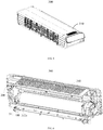
FIG. 6 is a schematic view showing a portion of the structure of the wall-mounted indoor unit inFIG. 5 ; -
FIG. 7 is a schematic view showing the cooperation of a device for cleaning an air conditioner with a filter screen inFIG. 6 ; -
FIG. 8 is a cross-sectional view showing a portion of the structure of the wall-mounted indoor unit inFIG. 5 ; and -
FIG. 9 is an enlarged view of portion A inFIG. 8 . - The realization of the objective, functional characteristics, advantages of the present disclosure are further described with reference to the accompanying drawings.
- The technical solutions of the embodiments of the present disclosure will be clearly and completely described in the following with reference to the accompanying drawings. It is obvious that the embodiments to be described are only a part rather than all of the embodiments of the present disclosure. Based on the embodiments of the present disclosure, all other embodiments obtained by those skilled in the art without creative efforts are within the scope of the present disclosure.
- It is to be understood that, all of the directional instructions in the embodiments of the present disclosure (such as top, bottom, left, right, front, rear...) can only be used for explaining relative position relations, moving condition of the elements under a special form (referring to figures), and so on, if the special form changes, the directional instructions changes accordingly.
- Besides, the technical solution of each embodiment can be combined with each other, however the technical solution must base on that the ordinary skill in that art can realize the technical solution, when the combination of the technical solutions is contradictory or cannot be realized, it should consider that the combination of the technical solutions does not exist, and is beyond the protection scope of the present disclosure.
- The present disclosure provides a water pump for use as a pressurized machine for conveying liquids (such as water, oil, solution, emulsion, and the like). The water pump can reduce the occurrence of water pump blockage and prolong the service life of the water pump.
- Referring to
FIG. 1 to FIG. 3 , awater pump 100 of the present disclosure includes apump body 110 defining awater outlet 102 and awater inlet 101 communicated with thewater outlet 102; and a plurality ofcolumns 120 disposed on thepump body 110 and surrounding thewater inlet 101. - Specially, the
pump body 110 includes thewater inlet 101 on the lower surface and thewater outlet 102 on the upper surface. A plurality ofcolumns 120 are disposed on the lower surface of thepump body 110 and surrounding thewater inlet 101. When thewater pump 100 is in operation, the liquid is driven to enter the inside of thewater pump 100 from thewater inlet 101, and then the liquid is driven to flow out from thewater outlet 102. During the influent process, the liquid flows from the gap between the plurality ofcolumns 120 to thewater inlet 101, and the flocculent materials in the liquid are wound around the plurality ofcolumns 120, which are not easily sucked into the interior by thewater pump 100. - The plurality of
columns 120 may surround thewater inlet 101 along a circular circumference. Of course, the plurality ofcolumns 120 can also surround thewater inlet 101 along the square circumference. Specifically, the corresponding design can be made according to the shape of thewater inlet 101 and the shape of thepump body 110, and is not limited herein. - In the technical solutions of the present disclosure, a plurality of
columns 120 are disposed on thewater pump 100, and the plurality ofcolumns 120 are disposed around thewater inlet 101 to be in the process of water entering thewater pump 100, the plurality ofcolumns 120 are used to wrap the flocculent materials in the liquid to prevent the flocculent materials from being sucked into thewater pump 100, thereby reducing the clogging of thewater pump 100 and prolonging the service life of thewater pump 100. In addition, since the flocculent materials are wound around thecolumn 120, when thewater pump 100 is cleaned, it is only necessary to pull down the flocculent materials from thecolumn 120, which is simple and easy to clean. - Referring to
FIG. 1 to FIG. 3 , in an embodiment, the plurality ofcolumns 120 may surround thewater inlet 101 one or more turns. It is considered here that if the plurality ofcolumns 120 wrap around thewater inlet 101 only one turn, it is possible that some of the flocculent materials are detached from thecolumn 120 under the strong suction of thewater pump 100, and are sucked into the inside of thewater pump 100. Therefore, the number of turns of the plurality ofcolumns 120 around thewater inlet 101 can be appropriately increased. - However, the number of turns is not as high as possible. When the number of turns is larger, the resistance of the liquid flow is larger, and the amount of liquid entering the
water pump 100 becomes smaller. Therefore, in order to ensure that thewater pump 100 has a better filtering effect and a larger amount of water inflow, optionally, the plurality ofcolumns 120 may surround thewater inlet 101 two or three turns. As for the number of thecolumns 120 per turn, it is only necessary to arrange according to the size of thecolumns 120 per turn, which is not specifically limited. - As for the shape and structure of the
column 120, it is not specifically limited. Thecolumn 120 may be arranged in a cylindrical shape, or may be arranged in a polygonal prism shape or in a flat shape. Specifically, the plurality ofcolumns 120 are arranged in a cylindrical shape, so that the resistance of thecolumn 120 to the liquid flow can be reduced, facilitating the liquid to pass through the gap between theadjacent columns 120 and flow to thewater inlet 101. - In addition, in view that the flocculent materials are lighter, they often float on the water. In order to improve the filtering effect of the
water pump 100, the outer diameter of thecolumn 120 may be gradually reduced in the height direction thereof. This can make thecolumn 120 "the upper end has a large diameter and the lower end has a small diameter", and the upper end of thecolumn 120 has a larger outer diameter, which is more convenient for winding the flocculent materials. The lower end of thecolumn 120 has a small outer diameter and a small resistance to water flow, which facilitates the water to pass through. - In an embodiment, in order to enhance the effect of filtering the flocculent materials of the plurality of
columns 120, the end surfaces of the plurality ofcolumns 120 are flush with each other. If a part of the flocculent materials are detached from thecolumn 120 in the peripheral region, it is finally entangled by thecolumn 120 of the inner region during the movement towards thewater inlet 101, thereby effectively improving the filtering effect. - Referring to
FIG. 1 to FIG. 3 , in an embodiment, in order to facilitate thewater pump 100 to drive the liquid from thewater inlet 101, thepump body 110 includes awater inlet column 114 protruded from a periphery of thewater inlet 101. When thewater pump 100 is used, only thewater inlet column 114 of thewater pump 100 is kept under the liquid surface to extract the liquid. For a specific position of the plurality ofcolumns 120 on thepump body 110, the plurality ofcolumns 120 are disposed on an end surface of thewater inlet column 114, and/or the plurality ofcolumns 120 are disposed on an outer periphery of thewater inlet column 114. - That is to say, the plurality of
columns 120 may be disposed entirely on the end surfaces of theinlet water column 114 to surround the position closer to thewater inlet 101. Alternatively, the plurality ofcolumns 120 may also be disposed on the outer periphery of thewater inlet column 114 to surround the peripheral position of thewater inlet 101. Alternatively, a portion of thecolumns 120 are disposed on the end surface of thewater inlet column 114, and the remaining portion of thecolumns 120 surround the outer periphery of thewater inlet column 114. - Specially, the plurality of
columns 120 includes a plurality offirst columns 120a and a plurality ofsecond columns 120b. Thefirst columns 120a are disposed on the end surface of thewater inlet column 114, and thesecond columns 120b surround the outer periphery of thewater inlet column 114. Since the circumference of thefirst column 120a is smaller than the circumference of thesecond column 120b, the number of thefirst columns 120a is smaller than the number of thesecond columns 120b. - Referring to
FIG. 1 to FIG. 3 , in an embodiment, a connectingrib 130 is disposed between each of the columns 120 (i.e., the aforementionedsecond column 120b) disposed on the outer periphery of thewater inlet column 114 and a corresponding side wall of thewater inlet column 114. The connectingrib 130 can strengthen the strength of thecolumn 120 and improve its stability. - Referring to
FIG. 1 to FIG. 3 , in an embodiment, a connectingplate 140 is disposed between two adjacent ones of the columns 120 (i.e., the aforementionedsecond column 120b) disposed on the outer periphery of thewater inlet column 114. The connectingplate 140 can not only strengthen the strength of thecolumn 120, but also improve its stability. Moreover, the connectingplate 140 can also intercept the flocculent materials floating on the liquid surface so as not to pass between thesecond columns 120b, thereby further improving the filtering effect. - Based on this, in order to improve the effect of the connecting
plate 140 for intercepting the flocculent materials, the connectingplate 140 includes three adjacent sides, and each of the three sides is connected to a surface of eachadjacent column 120, or a surface of thepump body 110. This design ensures that the connectingplate 140 intercepts the flocculent materials floating on the liquid surface outside thesecond columns 120b of the outer circumference. - Referring to
FIG. 2 to FIG. 4 , theoretically, the greater the height of the connectingplate 140 on the surface of thepump body 110, the more pronounced the effect of intercepting the flocculent materials. However, the gap between thecolumns 120 is also reduced, thereby reducing the throughput of the liquid. Therefore, in the present embodiment, the height of the connectingplate 140 on the surface of thepump body 110 is no less than one fifth of the height of thecolumn 120 connected to the connectingplate 140, and is no more than one-half of the height of thecolumn 120. - Specially, assuming that the height of the connecting
plate 140 on the surface of thepump body 110 is H1, and the height of the column 120 (i.e., thesecond column 120b) connected to the connectingplate 140 is H2. Then, H1 is no less than one fifth H2 and no more than one-half H2. For example, but not limited to: H1 is equal to one fifth H2, two fifth H2, and one-half H2. Thus, the connectingplate 140 can have a better effect of intercepting the flocculent materials and ensure that there is sufficient gap between the adjacent twosecond columns 120b to supply water through. - Referring to
FIG. 2 to FIG. 4 , further, in order to prevent the connectingplate 140 from blocking the flow of water into thewater inlet 101, the height of the connectingplate 140 on the surface of thepump body 110 is optionally smaller than the height of thewater inlet column 114 on the same surface of thepump body 110. Assuming that the height of thewater inlet column 114 on the same surface of thepump body 110 is H3, then H1 is less than H3. - Referring to
FIG. 1 to FIG. 3 , based on any of the above embodiments, thepump body 110 includes aseat 111, acover 112 and adriving blade 113. Theseat 111 has awater inlet 101, and acavity 103 communicating thewater inlet 101 with thewater outlet 102. Thecover 112 covers thecavity 103, and thedriving blade 113 penetrates through thecover 112 and is inserted into thecavity 103. - Specially, the
water inlet 101 is defined on the lower surface of theseat 111, and thewater outlet 102 is provided on the upper surface of thecover 112. A plurality ofcolumns 120 are disposed around thewater inlet 101. When thewater pump 100 is in operation, the blades are driven to rotate to draw external liquid into thecavity 103, and then flow out from thewater outlet 102. - Referring to
FIG. 5 to FIG. 7 , the present disclosure further provides a device for cleaning anair conditioner 200. Thedevice 200 includes awater collecting box 210 and awater pump 100, and awater outlet 102 of thewater pump 100 communicates with thewater collecting box 210 to supply water to thewater collecting box 210. The specific structure of thedevice 200 refers to the above embodiments. Since thedevice 200 adopts all the technical solutions of all the above embodiments, all the beneficial effects brought about by the technical solutions of the above embodiments are also not described herein. - Referring to
FIG. 5 and FIG. 6 , thedevice 200 is for cleaning an internal member of the wall-mountedindoor unit 300. The internal member may be a filter screen, a heat exchanger, or a cross flow wind turbine 320 or the like. Here, the internal member is specifically described as a filter screen as an example. - Referring to
FIG. 7 to FIG. 9 , in an embodiment, thedevice 200 is for cleaning thefilter screen 330. Thedevice 200 further includes a first rollingbrush 220, a second rollingbrush 230, and a driving assembly (not shown). The first rollingbrush 220 and the second rollingbrush 230 are disposed on thewater collecting box 210 in a top-and-bottom direction, and the driving assembly is connected to the first rollingbrush 220 and the second rollingbrush 230. - Specially, the upper end of the
water collecting box 210 is formed with an opening, and the first rollingbrush 220 is mounted to the opening and at least partially immersed under the water surface of thewater collecting box 210. Thesecond rolling brush 230 is located on the upper side of the first rollingbrush 220 and cooperates with the first rollingbrush 220 to clamp one end of the filter screen. The driving assembly is connected to the first rollingbrush 220 and the second rollingbrush 230 to drive the second rollingbrush 230 and the first rollingbrush 220 to rotate to drive the filter screen to move. During this process, the second rollingbrush 230 and the first rollingbrush 220 cooperate to brush the dirt on the filter screen. - Referring to
FIG. 7 , in an embodiment, thewater pump 100 is installed at the bottom of thewater collecting box 210. In order to facilitate the connection of thewater pump 100 to thewater collecting box 210, thewater pump 100 includes a pair oflugs 115 laterally protruded from the outer surface of thepump body 110, and connected to thewater collecting box 210. Thelug 115 and thewater collecting box 210 can be connected through a snap structure or a screw structure. Specifically, thelug 115 is provided with a through hole, and the through hole is connected to thewater collecting box 210 through a screw. - Referring to
FIG. 5 to FIG. 7 , the present disclosure further provides a wall-mountedindoor unit 300, including ahousing 310 and a device for cleaning anair conditioner 200. Thedevice 200 is mounted within thehousing 310 for cleaning the internal member of the wall-mountedindoor unit 300. The specific structure of thedevice 200 refers to the above embodiments. Since the wall-mountedindoor unit 300 adopts all the technical solutions of all the above embodiments, all the beneficial effects brought about by the technical solutions of the above embodiments are also not described herein. - Referring to
FIG. 5 to FIG. 7 , the wall-mountedindoor unit 300 further includes a cross flow wind turbine 320, a heater exchanger (not shown), and afilter screen 330. The cross flow wind turbine 320 and the heater exchanger are both mounted within thehousing 310. Thehousing 310 is defined with an air inlet, and afilter screen grille 340 is installed in the air inlet, and thefilter screen 300 is mounted on thefilter screen grille 340. - Referring to
FIG. 5 to FIG. 7 , the water source of thedevice 200 may be condensed water in the water receiving groove 301 of the wall-mountedindoor unit 300, or may be water outside the wall-mountedindoor unit 300. Herein, in order to improve the utilization of water resource, optionally, thehousing 310 includes achassis 311. Thechassis 311 is provided with a water receiving groove, and thewater pump 100 of thedevice 200 communicates with the water receiving groove 301. The water receiving groove 301 is configured to receive the condensed water generated by the heat exchanger of the wall-mountedindoor unit 300, and the condensed water is extracted by thewater pump 100 for cleaning the filter screen and the water resource utilization rate is improved without additional water source. - However, the wall-mounted
indoor unit 300 is usually installed in an indoor environment, and is easy to adsorb hair or fibers such as wool. When the flocculent materials fall within the water receiving groove 301, the flocculent materials enter thewater pump 100 along with the water of the water receiving groove 301, which is easy to block thewater pump 100 of the airconditioner cleaning device 200, or cause secondary pollution during the process of cleaning the internal members. - In view of this, in order to avoid the above, a plurality of
columns 120 of thewater pump 100 are inserted into the water receiving groove 301. During the water inflow of thewater pump 100, the liquid flows from the gap between the plurality ofcolumns 120 to thewater inlet 101, while the flocculent materials in the liquid are wound around the plurality ofcolumns 120, and are not easily sucked into the interior by thewater pump 100, thereby preventing thewater pump 100 from being clogged or secondary pollution during the cleaning process. - The present disclosure further provides an air conditioner. The air conditioner includes an outdoor unit and a wall-mounted indoor unit of the air conditioner connected to the outdoor unit through a refrigerant pipe. The specific structure of the wall-mounted indoor unit refers to the above embodiments. Since the air conditioner adopts all the technical solutions of all the above embodiments, all the beneficial effects brought about by the technical solutions of the above embodiments are also not described herein.
- The above are only alternative embodiments of the present disclosure, and thus do not limit the scope of the present disclosure. The equivalent structure or equivalent process transformations made by the present specification and the drawings are directly or indirectly applied to other related technical fields, and are included in the scope of the present disclosure.
| Label | | Label | Name | |
| 100 | | 130 | Connecting | |
| 110 | | 140 | Connecting | |
| 111 | | 200 | Device for cleaning an | |
| 112 | | 210 | | |
| 113 | | 220 | First rolling | |
| 114 | | 230 | Second | |
| 115 | | 300 | Wall-mounted | |
| 101 | | 310 | | |
| 102 | | 311 | | |
| 103 | Cavity | 301 | | |
| 120 | Column | 320 | Cross | |
| 120a | | 330 | | |
| 120b | | 340 | Filter screen grille |
Claims (19)
- A water pump, comprising:a pump body defining a water outlet and a water inlet communicated with the water outlet; anda plurality of columns disposed on the pump body and surrounding the water inlet.
- The water pump according to claim 1,
wherein the pump body comprises a water inlet column protruded from a periphery of the water inlet;
wherein the plurality of columns are disposed on an end surface of the water inlet column, and/or
wherein the plurality of columns are disposed on an outer periphery of the water inlet column. - The water pump according to claim 2, further comprising:
a connecting rib disposed between the columns disposed on the outer periphery of the water inlet column and a side wall of the water inlet column. - The water pump according to claim 2, further comprising:
a connecting plate disposed between two adjacent ones of the columns disposed on the outer periphery of the water inlet column. - The water pump according to claim 4,
wherein the connecting plate comprises three adjacent sides, and each of the three sides is connected to a surface of each adjacent column, or a surface of the pump body. - The water pump according to claim 5,
wherein a height of the connecting plate on the surface of the pump body is smaller than a height of the water inlet column on the same surface of the pump body. - The water pump according to claim 5,
wherein the height of the connecting plate on the surface of the pump body is no less than one fifth of a height of the column connected to the connecting plate, and is no more than one-half of the height of the column. - The water pump according to claim 6,
wherein end surfaces of the plurality of columns are flush with each other. - The water pump according to claim 1,
wherein an outer diameter of the column is gradually reduced in a height direction of the column. - The water pump according to claim 1,
wherein the plurality of columns are configured to twice or thirdly surround the water inlet. - The water pump according to claim 1, wherein the pump body comprises:a seat having the water inlet, and a cavity communicating the water inlet with the water outlet;a cover covering the cavity; anda driving blade penetrating through the cover and inserted into the cavity.
- A device for cleaning an air conditioner, comprising:a water collecting box; anda water pump, comprising:a pump body defining a water outlet and a water inlet communicated with the water outlet; anda plurality of columns disposed on the pump body and surrounding the water inlet, andwherein the water outlet of the water pump is in communication with the water collecting box.
- The device according to claim 12,
wherein the water pump comprises:
a pair of lugs laterally protruded from an outer surface of the pump body, and connected to the water collecting box. - The device according to claim 12, further comprising:a first rolling brush;a second rolling brush; anda driving assembly, andwherein the first rolling brush and the second rolling brush are disposed on the water collecting box in a top-and-bottom direction, and the driving assembly is connected to the first rolling brush and the second rolling brush.
- A wall-mounted indoor unit, comprising:a housing;a device for cleaning an air conditioner, mounted in the housing for cleaning an internal member of the wall-mounted indoor unit, and comprising:a water collecting box; anda water pump, comprising:a pump body defining a water outlet and a water inlet communicated with the water outlet; anda plurality of columns disposed on the pump body and surrounding the water inlet, andwherein the water outlet of the water pump is in communication with the water collecting box.
- The wall-mounted indoor unit according to claim 15,
wherein the housing comprises a chassis, the chassis is provided with a water receiving groove, and the water pump of the device is in communication with the water receiving groove. - The wall-mounted indoor unit according to claim 16,
wherein the plurality of columns of the water pump is inserted into the water receiving groove. - The wall-mounted indoor unit according to claim 15,
wherein the internal member is a filter screen of the wall-mounted indoor unit. - An air conditioner, comprising:an outdoor unit; anda wall-mounted indoor unit connected to the outdoor unit through a refrigerant pipe, and comprising:a housing;a device for cleaning an air conditioner, mounted in the housing for cleaning an internal member of the wall-mounted indoor unit, comprising:a water collecting box; anda water pump, comprising:a pump body defining a water outlet and a water inlet communicated with the water outlet, anda plurality of columns disposed on the pump body and surrounding the water inlet, andwherein the water outlet of the water pump is in communication with the water collecting box.
Applications Claiming Priority (3)
| Application Number | Priority Date | Filing Date | Title |
|---|---|---|---|
| CN201910159396.7A CN110017305B (en) | 2019-03-03 | 2019-03-03 | Water pump, air conditioning cleaning device, wall-mounted indoor unit and air conditioner |
| CN201920267970.6U CN209818406U (en) | 2019-03-03 | 2019-03-03 | Water pumps, air conditioner cleaning devices, wall-mounted indoor units and air conditioners |
| PCT/CN2019/112443 WO2020177332A1 (en) | 2019-03-03 | 2019-10-22 | Water pump, air conditioner cleaning device, wall-mounted indoor unit, and air conditioner |
Publications (3)
| Publication Number | Publication Date |
|---|---|
| EP3726065A1 true EP3726065A1 (en) | 2020-10-21 |
| EP3726065A4 EP3726065A4 (en) | 2021-02-24 |
| EP3726065B1 EP3726065B1 (en) | 2023-01-11 |
Family
ID=71786699
Family Applications (1)
| Application Number | Title | Priority Date | Filing Date |
|---|---|---|---|
| EP19798518.7A Active EP3726065B1 (en) | 2019-03-03 | 2019-10-22 | Water pump, air conditioner cleaning device, wall-mounted indoor unit, and air conditioner |
Country Status (3)
| Country | Link |
|---|---|
| EP (1) | EP3726065B1 (en) |
| JP (1) | JP7097911B2 (en) |
| WO (1) | WO2020177332A1 (en) |
Family Cites Families (28)
| Publication number | Priority date | Publication date | Assignee | Title |
|---|---|---|---|---|
| JPS512807Y2 (en) * | 1971-11-15 | 1976-01-27 | ||
| JPS5843679Y2 (en) * | 1978-03-22 | 1983-10-03 | 株式会社鶴見製作所 | Bottom water suction stand for portable vertical pumps |
| JPS5930072Y2 (en) * | 1978-10-14 | 1984-08-28 | 徳河 李 | Drain cleaning pump device |
| GB2118507B (en) * | 1982-04-19 | 1985-05-15 | Innerspace Corp | Turbomachine having self retracting screens] |
| JPS5984299U (en) * | 1982-11-29 | 1984-06-07 | 株式会社荏原製作所 | Strainer |
| JPS59170700U (en) * | 1983-04-30 | 1984-11-15 | 株式会社荏原製作所 | Strainer |
| JPS6099940A (en) * | 1983-11-02 | 1985-06-03 | Mitsubishi Electric Corp | Drain pump device for air conditioner |
| JPS62213621A (en) * | 1986-03-12 | 1987-09-19 | Toshiba Corp | Air conditioner |
| JPS6373597U (en) * | 1986-10-31 | 1988-05-17 | ||
| JPH055272Y2 (en) * | 1986-12-01 | 1993-02-10 | ||
| JPH01139098U (en) * | 1988-03-18 | 1989-09-22 | ||
| JPH0589886U (en) * | 1992-05-07 | 1993-12-07 | 株式会社クボタ | Portable submersible pump |
| JP3052623B2 (en) * | 1992-11-26 | 2000-06-19 | 株式会社デンソー | Regenerative pump |
| JP2006234259A (en) | 2005-02-24 | 2006-09-07 | Sharp Corp | Suction pump and air conditioner using the same |
| KR101319688B1 (en) | 2006-11-14 | 2013-10-17 | 엘지전자 주식회사 | Indoor unit for air conditioner |
| JP5081725B2 (en) * | 2008-05-29 | 2012-11-28 | 新明和工業株式会社 | underwater pump |
| JP2011257077A (en) | 2010-06-10 | 2011-12-22 | Fujitsu General Ltd | Air conditioner |
| CN104100572A (en) | 2014-07-09 | 2014-10-15 | 苏州优德通力电气有限公司 | Pump |
| CN206111601U (en) * | 2016-09-30 | 2017-04-19 | 浙江境界泵业有限公司 | Deep -well pump |
| CN106968959A (en) * | 2017-05-23 | 2017-07-21 | 宿迁洁丽环保设备制造有限公司 | A kind of sewage absorpting heat with crushing function |
| CN206753924U (en) * | 2017-05-23 | 2017-12-15 | 苏州优德通力科技有限公司 | A kind of intelligent control anti-clogging water cooling multipurpose pump |
| CN207334901U (en) * | 2017-07-21 | 2018-05-08 | 广东美的制冷设备有限公司 | Air conditioner room unit and there is its air conditioner |
| CN208169140U (en) * | 2018-03-19 | 2018-11-30 | 江苏省水利机械制造有限公司 | Pump means |
| CN208332483U (en) * | 2018-04-09 | 2019-01-04 | 广东美的制冷设备有限公司 | Air conditioner indoor unit and air conditioner |
| CN108644156A (en) * | 2018-06-25 | 2018-10-12 | 江苏斯别特制泵有限公司 | A kind of special high-power submerged dredge pump filtration |
| CN109139563B (en) * | 2018-08-17 | 2020-03-31 | 北京市朝阳水利工程有限公司 | Submersible sewage pump self-cooling device |
| CN109185987A (en) * | 2018-09-30 | 2019-01-11 | 广东美的制冷设备有限公司 | Washing module and air conditioner room unit |
| CN110017305B (en) * | 2019-03-03 | 2024-08-23 | 广东美的制冷设备有限公司 | Water pump, air conditioning cleaning device, wall-mounted indoor unit and air conditioner |
-
2019
- 2019-10-22 WO PCT/CN2019/112443 patent/WO2020177332A1/en not_active Ceased
- 2019-10-22 JP JP2019563167A patent/JP7097911B2/en active Active
- 2019-10-22 EP EP19798518.7A patent/EP3726065B1/en active Active
Also Published As
| Publication number | Publication date |
|---|---|
| EP3726065A4 (en) | 2021-02-24 |
| WO2020177332A1 (en) | 2020-09-10 |
| JP2021517625A (en) | 2021-07-26 |
| JP7097911B2 (en) | 2022-07-08 |
| EP3726065B1 (en) | 2023-01-11 |
Similar Documents
| Publication | Publication Date | Title |
|---|---|---|
| CN110017305B (en) | Water pump, air conditioning cleaning device, wall-mounted indoor unit and air conditioner | |
| EP3726065B1 (en) | Water pump, air conditioner cleaning device, wall-mounted indoor unit, and air conditioner | |
| CN209818406U (en) | Water pumps, air conditioner cleaning devices, wall-mounted indoor units and air conditioners | |
| CN208998314U (en) | A kind of drip tray maintenance structure and ceiling machine | |
| CN109520113B (en) | Water tray and air conditioner having the same | |
| CN209672460U (en) | Air conditioner indoor unit and air conditioner | |
| DE102004005500A1 (en) | vacuum cleaner | |
| CN220979600U (en) | Oil pan assembly and engine | |
| CN219578805U (en) | Floor washing machine | |
| CN209165517U (en) | " 7 " shape smoke exhaust ventilator | |
| CN216198570U (en) | Oil-water separator | |
| CN202520664U (en) | Filtering device of draining pump of air conditioner | |
| CN205878354U (en) | Wall -mounted air conditioner indoor unit and air conditioner | |
| CN221229284U (en) | Surface cleaning apparatus | |
| CN214998251U (en) | Water pump with sewage filtering function | |
| CN210565323U (en) | Fan drainage structure | |
| CN107178447A (en) | A kind of electric fuel punp oil sump | |
| CN211596119U (en) | Drain valve and washing machine using same | |
| CN212584017U (en) | Fan system and range hood with same | |
| CN222417638U (en) | Fume exhauster | |
| CN218366009U (en) | Air cushion ring on surface of barrier film | |
| CN223585855U (en) | Dust suction head and dust collector | |
| CN218485318U (en) | Filter screen and filter screen mounting structure | |
| CN205269298U (en) | A dust collecting equipment that is used for dust collecting equipment's filtrate case and has it | |
| CN221349384U (en) | A water collecting device with filtering function |
Legal Events
| Date | Code | Title | Description |
|---|---|---|---|
| STAA | Information on the status of an ep patent application or granted ep patent |
Free format text: STATUS: UNKNOWN |
|
| STAA | Information on the status of an ep patent application or granted ep patent |
Free format text: STATUS: THE INTERNATIONAL PUBLICATION HAS BEEN MADE |
|
| PUAI | Public reference made under article 153(3) epc to a published international application that has entered the european phase |
Free format text: ORIGINAL CODE: 0009012 |
|
| STAA | Information on the status of an ep patent application or granted ep patent |
Free format text: STATUS: REQUEST FOR EXAMINATION WAS MADE |
|
| 17P | Request for examination filed |
Effective date: 20191115 |
|
| AK | Designated contracting states |
Kind code of ref document: A1 Designated state(s): AL AT BE BG CH CY CZ DE DK EE ES FI FR GB GR HR HU IE IS IT LI LT LU LV MC MK MT NL NO PL PT RO RS SE SI SK SM TR |
|
| AX | Request for extension of the european patent |
Extension state: BA ME |
|
| A4 | Supplementary search report drawn up and despatched |
Effective date: 20210127 |
|
| RIC1 | Information provided on ipc code assigned before grant |
Ipc: F24F 1/0007 20190101ALI20210121BHEP Ipc: F24F 8/90 20210101ALI20210121BHEP Ipc: F04D 29/70 20060101AFI20210121BHEP Ipc: F04D 7/04 20060101ALI20210121BHEP Ipc: F04D 29/42 20060101ALI20210121BHEP Ipc: F24F 13/22 20060101ALI20210121BHEP Ipc: F04D 29/22 20060101ALN20210121BHEP Ipc: F04D 1/14 20060101ALN20210121BHEP |
|
| RAP3 | Party data changed (applicant data changed or rights of an application transferred) |
Owner name: MIDEA GROUP CO., LTD. Owner name: GD MIDEA AIR-CONDITIONING EQUIPMENT CO., LTD. |
|
| DAV | Request for validation of the european patent (deleted) | ||
| DAX | Request for extension of the european patent (deleted) | ||
| GRAP | Despatch of communication of intention to grant a patent |
Free format text: ORIGINAL CODE: EPIDOSNIGR1 |
|
| STAA | Information on the status of an ep patent application or granted ep patent |
Free format text: STATUS: GRANT OF PATENT IS INTENDED |
|
| INTG | Intention to grant announced |
Effective date: 20221021 |
|
| RIC1 | Information provided on ipc code assigned before grant |
Ipc: F04D 29/22 20060101ALN20221010BHEP Ipc: F04D 1/14 20060101ALN20221010BHEP Ipc: F24F 13/22 20060101ALI20221010BHEP Ipc: F24F 8/90 20210101ALI20221010BHEP Ipc: F24F 1/0007 20190101ALI20221010BHEP Ipc: F04D 29/42 20060101ALI20221010BHEP Ipc: F04D 7/04 20060101ALI20221010BHEP Ipc: F04D 29/70 20060101AFI20221010BHEP |
|
| GRAS | Grant fee paid |
Free format text: ORIGINAL CODE: EPIDOSNIGR3 |
|
| GRAA | (expected) grant |
Free format text: ORIGINAL CODE: 0009210 |
|
| STAA | Information on the status of an ep patent application or granted ep patent |
Free format text: STATUS: THE PATENT HAS BEEN GRANTED |
|
| AK | Designated contracting states |
Kind code of ref document: B1 Designated state(s): AL AT BE BG CH CY CZ DE DK EE ES FI FR GB GR HR HU IE IS IT LI LT LU LV MC MK MT NL NO PL PT RO RS SE SI SK SM TR |
|
| REG | Reference to a national code |
Ref country code: GB Ref legal event code: FG4D |
|
| REG | Reference to a national code |
Ref country code: CH Ref legal event code: EP |
|
| REG | Reference to a national code |
Ref country code: DE Ref legal event code: R096 Ref document number: 602019024354 Country of ref document: DE |
|
| REG | Reference to a national code |
Ref country code: IE Ref legal event code: FG4D |
|
| REG | Reference to a national code |
Ref country code: AT Ref legal event code: REF Ref document number: 1543586 Country of ref document: AT Kind code of ref document: T Effective date: 20230215 |
|
| REG | Reference to a national code |
Ref country code: LT Ref legal event code: MG9D |
|
| REG | Reference to a national code |
Ref country code: NL Ref legal event code: MP Effective date: 20230111 |
|
| REG | Reference to a national code |
Ref country code: AT Ref legal event code: MK05 Ref document number: 1543586 Country of ref document: AT Kind code of ref document: T Effective date: 20230111 |
|
| PG25 | Lapsed in a contracting state [announced via postgrant information from national office to epo] |
Ref country code: NL Free format text: LAPSE BECAUSE OF FAILURE TO SUBMIT A TRANSLATION OF THE DESCRIPTION OR TO PAY THE FEE WITHIN THE PRESCRIBED TIME-LIMIT Effective date: 20230111 |
|
| P01 | Opt-out of the competence of the unified patent court (upc) registered |
Effective date: 20230526 |
|
| PG25 | Lapsed in a contracting state [announced via postgrant information from national office to epo] |
Ref country code: RS Free format text: LAPSE BECAUSE OF FAILURE TO SUBMIT A TRANSLATION OF THE DESCRIPTION OR TO PAY THE FEE WITHIN THE PRESCRIBED TIME-LIMIT Effective date: 20230111 Ref country code: PT Free format text: LAPSE BECAUSE OF FAILURE TO SUBMIT A TRANSLATION OF THE DESCRIPTION OR TO PAY THE FEE WITHIN THE PRESCRIBED TIME-LIMIT Effective date: 20230511 Ref country code: NO Free format text: LAPSE BECAUSE OF FAILURE TO SUBMIT A TRANSLATION OF THE DESCRIPTION OR TO PAY THE FEE WITHIN THE PRESCRIBED TIME-LIMIT Effective date: 20230411 Ref country code: LV Free format text: LAPSE BECAUSE OF FAILURE TO SUBMIT A TRANSLATION OF THE DESCRIPTION OR TO PAY THE FEE WITHIN THE PRESCRIBED TIME-LIMIT Effective date: 20230111 Ref country code: LT Free format text: LAPSE BECAUSE OF FAILURE TO SUBMIT A TRANSLATION OF THE DESCRIPTION OR TO PAY THE FEE WITHIN THE PRESCRIBED TIME-LIMIT Effective date: 20230111 Ref country code: HR Free format text: LAPSE BECAUSE OF FAILURE TO SUBMIT A TRANSLATION OF THE DESCRIPTION OR TO PAY THE FEE WITHIN THE PRESCRIBED TIME-LIMIT Effective date: 20230111 Ref country code: ES Free format text: LAPSE BECAUSE OF FAILURE TO SUBMIT A TRANSLATION OF THE DESCRIPTION OR TO PAY THE FEE WITHIN THE PRESCRIBED TIME-LIMIT Effective date: 20230111 Ref country code: AT Free format text: LAPSE BECAUSE OF FAILURE TO SUBMIT A TRANSLATION OF THE DESCRIPTION OR TO PAY THE FEE WITHIN THE PRESCRIBED TIME-LIMIT Effective date: 20230111 |
|
| PG25 | Lapsed in a contracting state [announced via postgrant information from national office to epo] |
Ref country code: SE Free format text: LAPSE BECAUSE OF FAILURE TO SUBMIT A TRANSLATION OF THE DESCRIPTION OR TO PAY THE FEE WITHIN THE PRESCRIBED TIME-LIMIT Effective date: 20230111 Ref country code: PL Free format text: LAPSE BECAUSE OF FAILURE TO SUBMIT A TRANSLATION OF THE DESCRIPTION OR TO PAY THE FEE WITHIN THE PRESCRIBED TIME-LIMIT Effective date: 20230111 Ref country code: IS Free format text: LAPSE BECAUSE OF FAILURE TO SUBMIT A TRANSLATION OF THE DESCRIPTION OR TO PAY THE FEE WITHIN THE PRESCRIBED TIME-LIMIT Effective date: 20230511 Ref country code: GR Free format text: LAPSE BECAUSE OF FAILURE TO SUBMIT A TRANSLATION OF THE DESCRIPTION OR TO PAY THE FEE WITHIN THE PRESCRIBED TIME-LIMIT Effective date: 20230412 Ref country code: FI Free format text: LAPSE BECAUSE OF FAILURE TO SUBMIT A TRANSLATION OF THE DESCRIPTION OR TO PAY THE FEE WITHIN THE PRESCRIBED TIME-LIMIT Effective date: 20230111 |
|
| REG | Reference to a national code |
Ref country code: DE Ref legal event code: R097 Ref document number: 602019024354 Country of ref document: DE |
|
| PG25 | Lapsed in a contracting state [announced via postgrant information from national office to epo] |
Ref country code: SM Free format text: LAPSE BECAUSE OF FAILURE TO SUBMIT A TRANSLATION OF THE DESCRIPTION OR TO PAY THE FEE WITHIN THE PRESCRIBED TIME-LIMIT Effective date: 20230111 Ref country code: RO Free format text: LAPSE BECAUSE OF FAILURE TO SUBMIT A TRANSLATION OF THE DESCRIPTION OR TO PAY THE FEE WITHIN THE PRESCRIBED TIME-LIMIT Effective date: 20230111 Ref country code: EE Free format text: LAPSE BECAUSE OF FAILURE TO SUBMIT A TRANSLATION OF THE DESCRIPTION OR TO PAY THE FEE WITHIN THE PRESCRIBED TIME-LIMIT Effective date: 20230111 Ref country code: DK Free format text: LAPSE BECAUSE OF FAILURE TO SUBMIT A TRANSLATION OF THE DESCRIPTION OR TO PAY THE FEE WITHIN THE PRESCRIBED TIME-LIMIT Effective date: 20230111 Ref country code: CZ Free format text: LAPSE BECAUSE OF FAILURE TO SUBMIT A TRANSLATION OF THE DESCRIPTION OR TO PAY THE FEE WITHIN THE PRESCRIBED TIME-LIMIT Effective date: 20230111 |
|
| PLBE | No opposition filed within time limit |
Free format text: ORIGINAL CODE: 0009261 |
|
| STAA | Information on the status of an ep patent application or granted ep patent |
Free format text: STATUS: NO OPPOSITION FILED WITHIN TIME LIMIT |
|
| PG25 | Lapsed in a contracting state [announced via postgrant information from national office to epo] |
Ref country code: SK Free format text: LAPSE BECAUSE OF FAILURE TO SUBMIT A TRANSLATION OF THE DESCRIPTION OR TO PAY THE FEE WITHIN THE PRESCRIBED TIME-LIMIT Effective date: 20230111 |
|
| 26N | No opposition filed |
Effective date: 20231012 |
|
| PG25 | Lapsed in a contracting state [announced via postgrant information from national office to epo] |
Ref country code: SI Free format text: LAPSE BECAUSE OF FAILURE TO SUBMIT A TRANSLATION OF THE DESCRIPTION OR TO PAY THE FEE WITHIN THE PRESCRIBED TIME-LIMIT Effective date: 20230111 |
|
| PG25 | Lapsed in a contracting state [announced via postgrant information from national office to epo] |
Ref country code: MC Free format text: LAPSE BECAUSE OF FAILURE TO SUBMIT A TRANSLATION OF THE DESCRIPTION OR TO PAY THE FEE WITHIN THE PRESCRIBED TIME-LIMIT Effective date: 20230111 |
|
| REG | Reference to a national code |
Ref country code: CH Ref legal event code: PL |
|
| REG | Reference to a national code |
Ref country code: BE Ref legal event code: MM Effective date: 20231031 |
|
| PG25 | Lapsed in a contracting state [announced via postgrant information from national office to epo] |
Ref country code: LU Free format text: LAPSE BECAUSE OF NON-PAYMENT OF DUE FEES Effective date: 20231022 |
|
| GBPC | Gb: european patent ceased through non-payment of renewal fee |
Effective date: 20231022 |
|
| PG25 | Lapsed in a contracting state [announced via postgrant information from national office to epo] |
Ref country code: LU Free format text: LAPSE BECAUSE OF NON-PAYMENT OF DUE FEES Effective date: 20231022 |
|
| PG25 | Lapsed in a contracting state [announced via postgrant information from national office to epo] |
Ref country code: GB Free format text: LAPSE BECAUSE OF NON-PAYMENT OF DUE FEES Effective date: 20231022 |
|
| PG25 | Lapsed in a contracting state [announced via postgrant information from national office to epo] |
Ref country code: CH Free format text: LAPSE BECAUSE OF NON-PAYMENT OF DUE FEES Effective date: 20231031 |
|
| PG25 | Lapsed in a contracting state [announced via postgrant information from national office to epo] |
Ref country code: GB Free format text: LAPSE BECAUSE OF NON-PAYMENT OF DUE FEES Effective date: 20231022 Ref country code: CH Free format text: LAPSE BECAUSE OF NON-PAYMENT OF DUE FEES Effective date: 20231031 |
|
| PG25 | Lapsed in a contracting state [announced via postgrant information from national office to epo] |
Ref country code: BE Free format text: LAPSE BECAUSE OF NON-PAYMENT OF DUE FEES Effective date: 20231031 |
|
| PG25 | Lapsed in a contracting state [announced via postgrant information from national office to epo] |
Ref country code: IE Free format text: LAPSE BECAUSE OF NON-PAYMENT OF DUE FEES Effective date: 20231022 |
|
| PG25 | Lapsed in a contracting state [announced via postgrant information from national office to epo] |
Ref country code: IE Free format text: LAPSE BECAUSE OF NON-PAYMENT OF DUE FEES Effective date: 20231022 |
|
| PG25 | Lapsed in a contracting state [announced via postgrant information from national office to epo] |
Ref country code: BG Free format text: LAPSE BECAUSE OF FAILURE TO SUBMIT A TRANSLATION OF THE DESCRIPTION OR TO PAY THE FEE WITHIN THE PRESCRIBED TIME-LIMIT Effective date: 20230111 |
|
| PG25 | Lapsed in a contracting state [announced via postgrant information from national office to epo] |
Ref country code: BG Free format text: LAPSE BECAUSE OF FAILURE TO SUBMIT A TRANSLATION OF THE DESCRIPTION OR TO PAY THE FEE WITHIN THE PRESCRIBED TIME-LIMIT Effective date: 20230111 |
|
| PGFP | Annual fee paid to national office [announced via postgrant information from national office to epo] |
Ref country code: DE Payment date: 20241022 Year of fee payment: 6 |
|
| PGFP | Annual fee paid to national office [announced via postgrant information from national office to epo] |
Ref country code: FR Payment date: 20241024 Year of fee payment: 6 |
|
| PGFP | Annual fee paid to national office [announced via postgrant information from national office to epo] |
Ref country code: IT Payment date: 20241023 Year of fee payment: 6 |
|
| PG25 | Lapsed in a contracting state [announced via postgrant information from national office to epo] |
Ref country code: CY Free format text: LAPSE BECAUSE OF FAILURE TO SUBMIT A TRANSLATION OF THE DESCRIPTION OR TO PAY THE FEE WITHIN THE PRESCRIBED TIME-LIMIT; INVALID AB INITIO Effective date: 20191022 |
|
| PG25 | Lapsed in a contracting state [announced via postgrant information from national office to epo] |
Ref country code: HU Free format text: LAPSE BECAUSE OF FAILURE TO SUBMIT A TRANSLATION OF THE DESCRIPTION OR TO PAY THE FEE WITHIN THE PRESCRIBED TIME-LIMIT; INVALID AB INITIO Effective date: 20191022 |
|
| PG25 | Lapsed in a contracting state [announced via postgrant information from national office to epo] |
Ref country code: TR Free format text: LAPSE BECAUSE OF FAILURE TO SUBMIT A TRANSLATION OF THE DESCRIPTION OR TO PAY THE FEE WITHIN THE PRESCRIBED TIME-LIMIT Effective date: 20230111 |