EP3725857A1 - Cryogenic-assisted adhesive removal tool - Google Patents
Cryogenic-assisted adhesive removal tool Download PDFInfo
- Publication number
- EP3725857A1 EP3725857A1 EP20164506.6A EP20164506A EP3725857A1 EP 3725857 A1 EP3725857 A1 EP 3725857A1 EP 20164506 A EP20164506 A EP 20164506A EP 3725857 A1 EP3725857 A1 EP 3725857A1
- Authority
- EP
- European Patent Office
- Prior art keywords
- cryogenic
- adhesive
- tip
- removal tool
- cryogenic fluid
- Prior art date
- Legal status (The legal status is an assumption and is not a legal conclusion. Google has not performed a legal analysis and makes no representation as to the accuracy of the status listed.)
- Pending
Links
Images


Classifications
-
- B—PERFORMING OPERATIONS; TRANSPORTING
- B32—LAYERED PRODUCTS
- B32B—LAYERED PRODUCTS, i.e. PRODUCTS BUILT-UP OF STRATA OF FLAT OR NON-FLAT, e.g. CELLULAR OR HONEYCOMB, FORM
- B32B43/00—Operations specially adapted for layered products and not otherwise provided for, e.g. repairing; Apparatus therefor
- B32B43/006—Delaminating
-
- C—CHEMISTRY; METALLURGY
- C09—DYES; PAINTS; POLISHES; NATURAL RESINS; ADHESIVES; COMPOSITIONS NOT OTHERWISE PROVIDED FOR; APPLICATIONS OF MATERIALS NOT OTHERWISE PROVIDED FOR
- C09J—ADHESIVES; NON-MECHANICAL ASPECTS OF ADHESIVE PROCESSES IN GENERAL; ADHESIVE PROCESSES NOT PROVIDED FOR ELSEWHERE; USE OF MATERIALS AS ADHESIVES
- C09J5/00—Adhesive processes in general; Adhesive processes not provided for elsewhere, e.g. relating to primers
-
- B—PERFORMING OPERATIONS; TRANSPORTING
- B64—AIRCRAFT; AVIATION; COSMONAUTICS
- B64F—GROUND OR AIRCRAFT-CARRIER-DECK INSTALLATIONS SPECIALLY ADAPTED FOR USE IN CONNECTION WITH AIRCRAFT; DESIGNING, MANUFACTURING, ASSEMBLING, CLEANING, MAINTAINING OR REPAIRING AIRCRAFT, NOT OTHERWISE PROVIDED FOR; HANDLING, TRANSPORTING, TESTING OR INSPECTING AIRCRAFT COMPONENTS, NOT OTHERWISE PROVIDED FOR
- B64F5/00—Designing, manufacturing, assembling, cleaning, maintaining or repairing aircraft, not otherwise provided for; Handling, transporting, testing or inspecting aircraft components, not otherwise provided for
- B64F5/10—Manufacturing or assembling aircraft, e.g. jigs therefor
-
- B—PERFORMING OPERATIONS; TRANSPORTING
- B08—CLEANING
- B08B—CLEANING IN GENERAL; PREVENTION OF FOULING IN GENERAL
- B08B7/00—Cleaning by methods not provided for in a single other subclass or a single group in this subclass
- B08B7/0021—Cleaning by methods not provided for in a single other subclass or a single group in this subclass by liquid gases or supercritical fluids
-
- B—PERFORMING OPERATIONS; TRANSPORTING
- B08—CLEANING
- B08B—CLEANING IN GENERAL; PREVENTION OF FOULING IN GENERAL
- B08B7/00—Cleaning by methods not provided for in a single other subclass or a single group in this subclass
- B08B7/0064—Cleaning by methods not provided for in a single other subclass or a single group in this subclass by temperature changes
- B08B7/0092—Cleaning by methods not provided for in a single other subclass or a single group in this subclass by temperature changes by cooling
-
- B—PERFORMING OPERATIONS; TRANSPORTING
- B64—AIRCRAFT; AVIATION; COSMONAUTICS
- B64F—GROUND OR AIRCRAFT-CARRIER-DECK INSTALLATIONS SPECIALLY ADAPTED FOR USE IN CONNECTION WITH AIRCRAFT; DESIGNING, MANUFACTURING, ASSEMBLING, CLEANING, MAINTAINING OR REPAIRING AIRCRAFT, NOT OTHERWISE PROVIDED FOR; HANDLING, TRANSPORTING, TESTING OR INSPECTING AIRCRAFT COMPONENTS, NOT OTHERWISE PROVIDED FOR
- B64F5/00—Designing, manufacturing, assembling, cleaning, maintaining or repairing aircraft, not otherwise provided for; Handling, transporting, testing or inspecting aircraft components, not otherwise provided for
- B64F5/40—Maintaining or repairing aircraft
-
- F—MECHANICAL ENGINEERING; LIGHTING; HEATING; WEAPONS; BLASTING
- F25—REFRIGERATION OR COOLING; COMBINED HEATING AND REFRIGERATION SYSTEMS; HEAT PUMP SYSTEMS; MANUFACTURE OR STORAGE OF ICE; LIQUEFACTION SOLIDIFICATION OF GASES
- F25D—REFRIGERATORS; COLD ROOMS; ICE-BOXES; COOLING OR FREEZING APPARATUS NOT OTHERWISE PROVIDED FOR
- F25D3/00—Devices using other cold materials; Devices using cold-storage bodies
- F25D3/10—Devices using other cold materials; Devices using cold-storage bodies using liquefied gases, e.g. liquid air
-
- B—PERFORMING OPERATIONS; TRANSPORTING
- B32—LAYERED PRODUCTS
- B32B—LAYERED PRODUCTS, i.e. PRODUCTS BUILT-UP OF STRATA OF FLAT OR NON-FLAT, e.g. CELLULAR OR HONEYCOMB, FORM
- B32B38/00—Ancillary operations in connection with laminating processes
- B32B38/10—Removing layers, or parts of layers, mechanically or chemically
-
- C—CHEMISTRY; METALLURGY
- C09—DYES; PAINTS; POLISHES; NATURAL RESINS; ADHESIVES; COMPOSITIONS NOT OTHERWISE PROVIDED FOR; APPLICATIONS OF MATERIALS NOT OTHERWISE PROVIDED FOR
- C09J—ADHESIVES; NON-MECHANICAL ASPECTS OF ADHESIVE PROCESSES IN GENERAL; ADHESIVE PROCESSES NOT PROVIDED FOR ELSEWHERE; USE OF MATERIALS AS ADHESIVES
- C09J2301/00—Additional features of adhesives in the form of films or foils
- C09J2301/50—Additional features of adhesives in the form of films or foils characterized by process specific features
- C09J2301/502—Additional features of adhesives in the form of films or foils characterized by process specific features process for debonding adherents
-
- Y—GENERAL TAGGING OF NEW TECHNOLOGICAL DEVELOPMENTS; GENERAL TAGGING OF CROSS-SECTIONAL TECHNOLOGIES SPANNING OVER SEVERAL SECTIONS OF THE IPC; TECHNICAL SUBJECTS COVERED BY FORMER USPC CROSS-REFERENCE ART COLLECTIONS [XRACs] AND DIGESTS
- Y10—TECHNICAL SUBJECTS COVERED BY FORMER USPC
- Y10T—TECHNICAL SUBJECTS COVERED BY FORMER US CLASSIFICATION
- Y10T156/00—Adhesive bonding and miscellaneous chemical manufacture
- Y10T156/11—Methods of delaminating, per se; i.e., separating at bonding face
- Y10T156/1153—Temperature change for delamination [e.g., heating during delaminating, etc.]
-
- Y—GENERAL TAGGING OF NEW TECHNOLOGICAL DEVELOPMENTS; GENERAL TAGGING OF CROSS-SECTIONAL TECHNOLOGIES SPANNING OVER SEVERAL SECTIONS OF THE IPC; TECHNICAL SUBJECTS COVERED BY FORMER USPC CROSS-REFERENCE ART COLLECTIONS [XRACs] AND DIGESTS
- Y10—TECHNICAL SUBJECTS COVERED BY FORMER USPC
- Y10T—TECHNICAL SUBJECTS COVERED BY FORMER US CLASSIFICATION
- Y10T156/00—Adhesive bonding and miscellaneous chemical manufacture
- Y10T156/11—Methods of delaminating, per se; i.e., separating at bonding face
- Y10T156/1168—Gripping and pulling work apart during delaminating
- Y10T156/1179—Gripping and pulling work apart during delaminating with poking during delaminating [e.g., jabbing, etc.]
- Y10T156/1184—Piercing layer during delaminating [e.g., cutting, etc.]
-
- Y—GENERAL TAGGING OF NEW TECHNOLOGICAL DEVELOPMENTS; GENERAL TAGGING OF CROSS-SECTIONAL TECHNOLOGIES SPANNING OVER SEVERAL SECTIONS OF THE IPC; TECHNICAL SUBJECTS COVERED BY FORMER USPC CROSS-REFERENCE ART COLLECTIONS [XRACs] AND DIGESTS
- Y10—TECHNICAL SUBJECTS COVERED BY FORMER USPC
- Y10T—TECHNICAL SUBJECTS COVERED BY FORMER US CLASSIFICATION
- Y10T156/00—Adhesive bonding and miscellaneous chemical manufacture
- Y10T156/19—Delaminating means
- Y10T156/1911—Heating or cooling delaminating means [e.g., melting means, freezing means, etc.]
-
- Y—GENERAL TAGGING OF NEW TECHNOLOGICAL DEVELOPMENTS; GENERAL TAGGING OF CROSS-SECTIONAL TECHNOLOGIES SPANNING OVER SEVERAL SECTIONS OF THE IPC; TECHNICAL SUBJECTS COVERED BY FORMER USPC CROSS-REFERENCE ART COLLECTIONS [XRACs] AND DIGESTS
- Y10—TECHNICAL SUBJECTS COVERED BY FORMER USPC
- Y10T—TECHNICAL SUBJECTS COVERED BY FORMER US CLASSIFICATION
- Y10T156/00—Adhesive bonding and miscellaneous chemical manufacture
- Y10T156/19—Delaminating means
- Y10T156/1961—Severing delaminating means [e.g., chisel, etc.]
- Y10T156/1967—Cutting delaminating means
Definitions
- the disclosure relates to the field of fabrication and repair, and in particular, to removal of material from fabricated parts.
- Adhesive features are applied to a variety of locations on an aircraft to prevent fuel leakage, provide erosion resistance, grant aeronautical benefits, grant specific optical and performance properties, and protect the aircraft from corrosion and other effects of environmental exposure.
- Adhesive features are adhered to the surface of an aircraft via chemical means, and have a limited lifetime.
- the adhesive features can also protect and assist other components on the aircraft which themselves have limited lifetimes. Removal of these other components may necessitate removal of their corresponding adhesive feature. Removal of adhesive features is difficult because their elastomeric properties tend to cause them to deform rather than be cleaved or otherwise separated from the surface on which they are installed.
- the elastomeric properties of adhesive features may result in a gumming up of the cleaving or separating edge of the removal tool and/or the underlying surface, because the material being removed tends to stick to everything that it contacts.
- Examples described herein include removal tools that apply cryogenic gases to provide localized cooling which reduces the temperature of adhesive features applied to a surface. This makes the adhesive features brittle and easier to mechanically remove (e.g., scrape).
- the removal tools also include cleaving/scraping edges or tips that facilitate mechanical-based removal of adhesive features, while maintaining integrity of the surface.
- An example is a method for operating a cryogenic-assisted adhesive a removal tool. The method includes dispensing a cryogenic fluid onto an adhesive feature disposed at a surface of a structure, cooling the adhesive feature to cause a physical change making the adhesive feature brittle, and operating the cryogenic-assisted adhesive removal tool to cleave the adhesive feature from the surface while the adhesive feature is physically changed.
- a further example is an apparatus for performing cryogenic cleaving.
- the apparatus includes a barrel that includes a dispensing pathway for cryogenic fluid to travel, a tip coupled with the barrel that provides a port for the cryogenic fluid to exit the dispensing pathway, and that includes a cleaving surface, and a trigger that controllably activates dispensing of the cryogenic fluid via the dispensing pathway.
- a further example is a system for performing cryogenic cleaving.
- the system includes a cryogenic fluid reservoir, and a cryogenic-assisted adhesive removal tool that is coupled with the cryogenic fluid reservoir and that dispenses cryogenic fluid stored within the cryogenic fluid reservoir from a cleaving tip of the cryogenic-assisted adhesive removal tool.
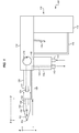
- FIG. 1 illustrates a cryogenic-assisted adhesive removal tool 100.
- Cryogenic-assisted adhesive removal tool 100 comprises any system, device, or component operable to dispense a cryogenic fluid (e.g., a gas or liquid that is colder than ambient temperature) to an adhesive feature that has been applied atop a surface of a structure (e.g., a portion of an aircraft).
- Cryogenic-assisted adhesive removal tool 100 is also able to perform cleaving of the surface to remove the adhesive feature while the adhesive feature is cooled to a degree that it exhibits a physical change (e.g., is cooled below a glass transition temperature, such as a glass transition temperature of a chemical sealant that secures the adhesive feature in place).
- Cryogenic-assisted adhesive removal tool 100 provides a technical benefit over prior scraping tools because it provides cooling that cause a physical change resulting in increased brittleness within a material used in the adhesive feature. This results in the adhesive feature becoming brittle, which enhances the ease with which the feature is removed via cleaving. Hence, less force is needed to separate the adhesive features from the surface, which reduces the likelihood of an operator applying amounts of force that are undesirable. In other words, less applied force is needed, which reduces likelihood of an operator applied applying an amount of force that would undesirably mark the underlying surface.
- the cryogenic-assisted adhesive removal tool 100 may comprise handle 112 and body 114, which together with trigger guard 116 and housing 118 define the overarching structure and shape of cryogenic-assisted adhesive removal tool 100.
- These components may be shaped according to any desired ergonomic constraints, and may be made from metal, plastic, ceramics, etc. In other examples, these components are made from materials that retain their strength when exposed to the cryogenic fluid. In other examples, these components are coated with rubber or a rubberized compound to increase grip.
- Housing 118 structurally supports a coupling 142, which leads to a dispensing pathway 145, and also structurally supports a coupling 144, which leads to a vacuum pathway 143. Housing 118 may further provide thermal insulation in order to prevent convective or conductive cooling of an operator's hand during operation.
- the dispensing pathway 145 dispenses the cryogenic fluid from a reservoir outward through barrel 120 and protrusion 122 of the tool.
- vacuum pathway 143 may apply negative pressure/vacuum that extracts/draws applied cryogenic fluid away from an application area (e.g., a surface of an aircraft) via vacuum inlet 160. This prevents the amount/concentration of cryogenic fluid outside of the tool from increasing beyond a desired amount, which may ensure air quality and/or a desired range of temperatures near an operator.
- Pressure at which the cryogenic fluid is dispensed may be controlled via pressure regulator 170, which may comprise a manual valve controlled by a knob.
- pressure regulator 170 may be implemented as or controlled by, for example, custom circuitry, a hardware processor executing programmed instructions, or some combination thereof that implements feedback-based pressure and/or flow control.
- protrusion 122 includes mating features 124 (e.g., spring-loaded ball bearings, mating pins, cams, etc.).
- mating features 124 e.g., spring-loaded ball bearings, mating pins, cams, etc.
- mating features 156 e.g., cut-outs, notches, or spring-loaded detents
- Tip 150 operates as an extended pathway via which the cryogenic fluid travels, and includes one or more ports 158 (e.g., openings, nozzles, diffusers, etc.) for dispensing, such as spraying, the cryogenic fluid proximate to a location where scraping/cleaving will commence. This makes elastomeric materials within the adhesive feature brittle before they are cleaved off.
- Tip 150 further comprises a cleaving surface 152 and an edge 153 for physically cleaving a desired location.
- Cleaving surface 152 may be static, may be driven at a high level of rotary speed, or may even rapidly oscillate (e.g., back and forth, side-to-side, etc.) to facilitate removal of adhesive features.
- Tip 150 may be made from any suitable material, and may for example be made from materials which, in the desired range of operating temperatures have sufficient stiffness and strength that will allow for efficient removal of the adhesive feature, yet soft enough that they will not scratch or gouge the underlying surface upon which the adhesive features reside.
- tip 150 may be made from nylon, polyamide-imide, polyether-imide, phenolic, acrylic, fluoropolymers, and other engineered polymers. This reduces the likelihood of tip 150 scratching the surface during operation.
- polymeric tips may be selected which do not become brittle when cooled to the operating range of cryogenic-assisted adhesive removal tool 100, and that have high wear resistance, impact resistance, fatigue resistance, and mechanical strength.
- the polymeric tips may be selected such that any change in hardness of the tip (caused by cooling the tip to the cryogenic operating range) does not cause marks upon the surface. This ensures that the adhesive is cleaved from the surface without causing any undesired or out of tolerance marking or gouging at the surface.
- cryogenic-assisted adhesive removal tool 100 Illustrative details of the operation of cryogenic-assisted adhesive removal tool 100 will be discussed with regard to FIG. 1 . Assume, for this example, that an adhesive feature is chemically secured to a surface of a structure (e.g., a portion of an aircraft) and awaits removal. Further, assume that cryogenic-assisted adhesive removal tool 100 has been coupled with a cryogenic fluid reservoir and a vacuum supply.
- FIG. 2 is a flowchart illustrating a method for operating a cryogenic-assisted adhesive removal tool.
- the steps of method 200 are described with reference to cryogenic-assisted adhesive removal tool 100 of FIG. 1 , but those skilled in the art will appreciate that method 200 may be performed with other tools as desired.
- the steps of the flowcharts described herein are not all inclusive and may include other steps not shown. The steps described herein may also be performed in an alternative order.
- the cryogenic fluid may comprise a gas or liquid, and may be selected from among carbon dioxide, nitrogen (which liquefies at negative two hundred and ten degrees Celsius), helium, argon, or others. Carbon dioxide may provide additional benefits beyond cooling, for example by dissolving adhesive compounds and acting as a cleaning solvent.
- the cryogenic fluid may be dispensed at a temperature cooler than ambient temperature, such as a temperature below a glass transition temperature of the adhesive feature.
- the cryogenic fluid may be dispensed at temperatures less than zero degrees Celsius, ranging down to negative one hundred ninety-five degrees Celsius.
- the pressure and volumetric flow of the cryogenic fluid may be selected as desired based on an expected rate of removal and a thermal mass of the adhesive feature per unit area. In some examples, pressures range between one and fifty Pounds per Square Inch (1.03 MPa), and volumetric flow rates range between one liter per minute and one liter per second.
- Dispensing the cryogenic fluid includes spraying the cryogenic fluid at a tip of the cryogenic-assisted adhesive removal tool that cleaves the adhesive feature.
- dispensing the cryogenic fluid includes spraying the cryogenic fluid from a tip of the cryogenic-assisted adhesive removal tool that cleaves the adhesive feature.
- the cryogenic fluid cools the adhesive feature to cause a physical change making the adhesive feature brittle (e.g., by cooling the adhesive feature below the glass transition temperature of a chemical that secures the adhesive feature in place).
- the cryogenic fluid may cool the adhesive feature via convective and/or conductive heat transfer. This causes the chemical, and/or the entire adhesive feature, to become brittle.
- the cryogenic fluid also cools the tip 150 of the cryogenic-assisted adhesive removal tool 100, which ensures that contact between the tip 150 and the adhesive feature does not result in conductive or frictional heating of the adhesive feature above the temperature at which the physical change occurred (e.g., the glass transition temperature). In this manner, the cryogenic fluid ensures that both the tip 150 of the cryogenic tool and the adhesive feature itself remain cool enough that the adhesive feature may be effectively chipped or cleaved away from its underlying surface.
- the cryogenic-assisted adhesive removal tool 100 is operated to cleave (e.g., mechanically remove) the adhesive feature from the surface while the adhesive feature is physically changed/cooled (e.g., is below its glass transition temperature), to remove the adhesive feature from the structure.
- cleave e.g., mechanically remove
- the adhesive feature is physically changed/cooled (e.g., is below its glass transition temperature)
- an operator of the cryogenic-assisted adhesive removal tool may move the tip 150 back and forth across the adhesive feature while pressing the tip into the surface of the structure.
- the operator may activate a motorized system that drives the tip in order to facilitate cleaving.
- Method 200 provides a technical benefit over prior systems, because it provides a removal technique which utilizes cooling to alter the physical properties of material that is being removed. This increases the ease with which the material is removed, for example by causing the material may lose elastomeric properties that would otherwise have made it difficult to cleave. Thus, operators may beneficially remove adhesive features in less time and with less effort than was previously possible and without undesired marks being created on the underlying surface that the adhesive feature resides on.
- FIGS. 3-4 are views of a first interchangeable tip 300 for a cryogenic-assisted adhesive removal tool, and correspond with view arrows 3 and 4 of FIG. 1 , respectively.
- first interchangeable tip 300 includes body 320, from which surface 310 extends, ending in edge 312.
- a cavity 330 within body 320 includes mating features 332 for receiving mating features at a protrusion of a cryogenic-assisted adhesive removal tool.
- Passages 334 extend from cavity 330, forming a manifold 336 that leads to ports 340 for dispensing cryogenic fluid. Ports 340 therefore allow cryogenic fluid to be dispensed onto a surface, while passages 334 provide cooling for surface 310.
- Edge 312 of first interchangeable tip 300 may be manually moved across an adhesive feature to cleave the adhesive feature, or edge 312 may be mechanically driven to oscillate or rotate at a desired rate to facilitate cleaving.
- the first interchangeable tip has an edge 312 with a length (L) of one quarter of an inch.
- the ports 340 from which cryogenic jets are dispensed to impinge upon a work surface as close as possible to the edge 312.
- the angle of the passages 334 and/or ports 340 is oriented to project cryogenic fluid towards edge 312 or a point at a surface contacted by edge 312 (or as close as is possible).
- Edge 312 may then be oscillated (e.g., manually) at a rate of multiple times per second while edge 312 and the underlying surface are cooled by the cryogenic fluid.
- FIGS. 5-6 are views of a second interchangeable tip 500 for a cryogenic-assisted adhesive removal tool, and correspond with the views depicted in FIGS. 3 and 4 .
- second interchangeable tip 500 includes body 520, from which cleaving surface 510 extends, ending in edge 512.
- a cavity 530 within body 520 includes mating features 532 for receiving mating features at a protrusion of a cryogenic-assisted adhesive removal tool.
- Passages 534 extend from cavity 530, forming a manifold 536 that leads to ports 540 for dispensing cryogenic fluid. Ports 540 allow cryogenic fluid to be dispensed onto a surface, while passages 534 provide cooling for surface 310.
- Passages 534 therefore operate as a type of manifold.
- Edge 512 of second interchangeable tip 500 may be manually moved across an adhesive feature to cleave the adhesive feature, or edge 512 may be mechanically driven to facilitate cleaving.
- the second interchangeable tip 500 has an edge 512 with a length (L) of several inches (e.g. 5 to 15 cm).
- the second interchangeable tip 500 has longer lengths, such as lengths of several feet (e.g. 1 to 3 m).
- FIGS. 7-9 illustrate operation of a cryogenic-assisted adhesive removal tool 730 to remove an adhesive feature.
- cryogenic-assisted adhesive removal tool 730 is coupled with a cryogenic gas reservoir 740 via dispensing pathway 742, and is coupled with a vacuum system 750 via a vacuum pathway 752.
- Cryogenic-assisted adhesive removal tool 730 will be used to remove an adhesive feature 720 (e.g., a decal) from surface 712 of a structure comprising a wing 710 of an aircraft.
- an adhesive feature 720 e.g., a decal
- cryogenic-assisted adhesive removal tool 730 is disposed over a portion 810 of the adhesive feature 720, and a trigger of the cryogenic-assisted adhesive removal tool is actuated to dispense cryogenic fluid 800 in the form of carbon dioxide gas that has been cooled to negative fifty degrees Celsius (carbon dioxide sublimates from a solid to gas at negative fifty six degrees Celsius at atmospheric pressure, and liquefies at five point one atmospheres in certain temperature ranges).
- the cryogenic fluid 800 rapidly reduces a temperature of the portion 810 of the adhesive feature 720 to cool the adhesive feature or a chemical (e.g., an epoxy, glue, or resin) that bonds the adhesive feature to surface 712, as shown by the indicator ⁇ T.
- the cooling results in a physical change that causes the adhesive feature or the chemical to become more brittle. This circumvents the ability of the adhesive feature to remain elastomeric and capable of deformation, and hence facilitates cleaving of the adhesive feature from the underlying surface.
- the material can be chipped or shattered, enabling it to be decoupled from the underlying surface.
- the cryogenic-assisted adhesive removal tool 730 is operated to cleave away the portion 810 of the adhesive feature 720, leaving a segment 900 behind.
- the cryogenic-assisted adhesive removal tool 730 may be operated again as shown in FIGS. 7-8 to dispense cryogenic fluid onto remaining portions of adhesive feature 720 and cleave them away. This process may be repeated until adhesive feature 720 has been completely removed.
- FIG. 10 illustrates a cryogenic-assisted adhesive removal tool 1000 with a shroud 1010.
- Shroud 1010 is transparent, and reduces the likelihood that cryogenic fluid exiting the tool will travel towards a user of the apparatus, while also enabling an operator to view a work location. That is, cryogenic fluid exiting the cryogenic-assisted adhesive removal tool 1000 is physically blocked from freely traveling more than a certain distance laterally (L, of FIG. 10 ) when it is ejected out of cryogenic-assisted adhesive removal tool 1000, and therefore must proceed within the bounds of shroud 1010.
- L certain distance laterally
- cryogenic-assisted adhesive removal tool 1000 This enhances the safety of an operator of the cryogenic-assisted adhesive removal tool 1000, by preventing cryogenic fluid from moving towards portions of cryogenic-assisted adhesive removal tool 1000 that are held by the operator.
- the jets of cryogenic fluid that impinge upon the surface that ricochet off the surface are deflected off of the shroud 1010, and remain safely apart from the operator.
- FIG. 11 illustrates a cryogenic-assisted adhesive removal tool 1100 with a debris vacuum port 1110.
- Debris vacuum port 1110 leads to a vacuum pathway 1120 having a large-diameter, such as a vacuum pathway having a diameter of one to several inches.
- the increased size of the vacuum pathway 1120 enables debris 1130 generated as part of the cleaving process to be quickly and efficiently removed from the work area in which cryogenic-assisted adhesive removal tool 1100 is used.
- FIG. 12 is a block diagram of a cryogenic cleaving system 1200.
- Cryogenic cleaving system 1200 is provided in the form of a tool, such as the tool 100 (shown in FIG. 1 ), which is coupled with a cryogenic fluid reservoir 1282 and a vacuum system 1284.
- cryogenic cleaving system 1200 includes handle 1212, which is physically integral with body 1214, guard 1216, and housing 1218.
- Housing 1218 includes coupling 1242 and coupling 1244, which enable the passage of fluid (e.g., liquid or gas) for cryogenic fluid reservoir 1282 and vacuum system 1284, respectively.
- Body 1214 includes pressure regulator 1270, which enables an adjustment of pressure and/or flow rate for the cryogenic fluid that will be dispensed.
- Vacuum inlet 1260 extracts applied cryogenic fluid from near tip 1250, preventing build-up of the cryogenic fluid. In some examples, vacuum inlet 1260 also extracts fragments of the adhesive/sealant that have been cleaved or chipped away.
- cryogenic jets are manifolded through the cryogenic cleaving system and impinged upon a work area to make any flexible materials thereon brittle and chippable/cleav able.
- method 1300 may include specification and design 1304 of the aircraft 1302 and material procurement 1306.
- component and subassembly manufacturing 1308 and system integration 1310 of the aircraft 1302 takes place.
- the aircraft 1302 may go through certification and delivery 1312 in order to be placed in service 1314.
- the aircraft 1302 is scheduled for routine work in maintenance and service 1316 (which may also include modification, reconfiguration, refurbishment, and so on).
- Apparatus and methods embodied herein may be employed during any one or more suitable stages of the production and service described in method 1300 (e.g., specification and design 1304, material procurement 1306, component and subassembly manufacturing 1308, system integration 1310, certification and delivery 1312, service 1314, maintenance and service 1316) and/or any suitable component of aircraft 1302 (e.g., airframe 1318, systems 1320, interior 1322, propulsion system 1324, electrical system 1326, hydraulic system 1328, environmental system 1330).
- any suitable component of aircraft 1302 e.g., airframe 1318, systems 1320, interior 1322, propulsion system 1324, electrical system 1326, hydraulic system 1328, environmental system 1330.
- a system integrator may include without limitation any number of aircraft manufacturers and major-system subcontractors; a third party may include without limitation any number of vendors, subcontractors, and suppliers; and an operator may be an airline, leasing company, military entity, service organization, and so on.
- the aircraft 1302 produced by method 1300 may include an airframe 1318 with a plurality of systems 1320 and an interior 1322.
- systems 1320 include one or more of a propulsion system 1324, an electrical system 1326, a hydraulic system 1328, and an environmental system 1330. Any number of other systems may be included.
- an aerospace example is shown, the principles of the disclosure may be applied to other industries, such as the automotive industry or construction industry.
- apparatus and methods embodied herein may be employed during any one or more of the stages of the production and service described in method 1300.
- components or subassemblies corresponding to component and subassembly manufacturing 1308 may be fabricated or manufactured in a manner similar to components or subassemblies produced while the aircraft 1302 is in service.
- one or more apparatus examples, method examples, or a combination thereof may be utilized during the subassembly manufacturing 1308 and system integration 1310, for example, by expediting (or substantially expediting) assembly of or reducing the cost of an aircraft 1302.
- one or more of apparatus examples, method examples, or a combination thereof may be utilized while the aircraft 1302 is in service, for example and without limitation during the maintenance and service 1316.
- the techniques and systems described herein may be used for material procurement 1306, component and subassembly manufacturing 1308, system integration 1310, service 1314, and/or maintenance and service 1316, and/or may be used for airframe 1318 and/or interior 1322.
- These techniques and systems may even be utilized for systems 1320, including, for example, propulsion system 1324, electrical system 1326, hydraulic system 1328, and/or environmental system 1330.
- a part comprises a portion of airframe 1318, and is manufactured during component and subassembly manufacturing 1308.
- the part may then be assembled into an aircraft in system integration 1310, and then be utilized in service 1314 until wear renders the part unusable. Then, in maintenance and service 1316, the part may be discarded and replaced with a newly manufactured part.
- Inventive components and methods may be utilized throughout component and subassembly manufacturing 1308 in order to manufacture new parts.
- control elements e.g., electrical or electronic components
- a processor implementing software
- a processor implementing firmware or some combination of these.
- an element may be implemented as dedicated hardware.
- Dedicated hardware elements may be referred to as "processors", “controllers”, or some similar terminology.
- the functions may be provided by a single dedicated processor, by a single shared processor, or by a plurality of individual processors, some of which may be shared.
- processor or “controller” should not be construed to refer exclusively to hardware capable of executing software, and may implicitly include, without limitation, digital signal processor (DSP) hardware, a network processor, application specific integrated circuit (ASIC) or other circuitry, field programmable gate array (FPGA), read only memory (ROM) for storing software, random access memory (RAM), non-volatile storage, logic, or some other physical hardware component or module.
- DSP digital signal processor
- ASIC application specific integrated circuit
- FPGA field programmable gate array
- ROM read only memory
- RAM random access memory
- non-volatile storage logic, or some other physical hardware component or module.
- a control element may be implemented as instructions executable by a processor or a computer to perform the functions of the element.
- instructions are software, program code, and firmware.
- the instructions are operational when executed by the processor to direct the processor to perform the functions of the element.
- the instructions may be stored on storage devices that are readable by the processor. Some examples of the storage devices are digital or solid-state memories, magnetic storage media such as a magnetic disks and magnetic tapes, hard drives, or optically readable digital data storage media.
Landscapes
- Engineering & Computer Science (AREA)
- Manufacturing & Machinery (AREA)
- Aviation & Aerospace Engineering (AREA)
- Transportation (AREA)
- Chemical & Material Sciences (AREA)
- Mechanical Engineering (AREA)
- General Engineering & Computer Science (AREA)
- Thermal Sciences (AREA)
- Physics & Mathematics (AREA)
- Combustion & Propulsion (AREA)
- Organic Chemistry (AREA)
- Jigs For Machine Tools (AREA)
- Details Or Accessories Of Spraying Plant Or Apparatus (AREA)
- Application Of Or Painting With Fluid Materials (AREA)
- Nozzles (AREA)
- Cleaning In General (AREA)
- Adhesives Or Adhesive Processes (AREA)
- Filling Or Discharging Of Gas Storage Vessels (AREA)
Abstract
Description
- The disclosure relates to the field of fabrication and repair, and in particular, to removal of material from fabricated parts.
- Adhesive features (e.g., sealants, adhesives, decals, appliqués and other features having flexible or elastomeric properties) are applied to a variety of locations on an aircraft to prevent fuel leakage, provide erosion resistance, grant aeronautical benefits, grant specific optical and performance properties, and protect the aircraft from corrosion and other effects of environmental exposure. Adhesive features are adhered to the surface of an aircraft via chemical means, and have a limited lifetime. The adhesive features can also protect and assist other components on the aircraft which themselves have limited lifetimes. Removal of these other components may necessitate removal of their corresponding adhesive feature. Removal of adhesive features is difficult because their elastomeric properties tend to cause them to deform rather than be cleaved or otherwise separated from the surface on which they are installed. Furthermore, the elastomeric properties of adhesive features may result in a gumming up of the cleaving or separating edge of the removal tool and/or the underlying surface, because the material being removed tends to stick to everything that it contacts.
- Removal of adhesive features remains difficult due to the tenacious nature of the materials that they are made from. These materials tend to be elastomeric and tightly adhered to the surface. When used properly, tools designed for removal of adhesive features allow for a labor-intensive mechanical removal process. However, there is the potential that tools designed for removal of adhesive features will be used improperly, for example due to operator fatigue or impatience. When used improperly, the tools can be damaged, can mark the surface of the aircraft, or can remove less or more than desired amounts of the adhesive feature from the aircraft surface.
- Therefore, it would be desirable to have a method and apparatus that take into account at least some of the issues discussed above, as well as other possible issues.
- Examples described herein include removal tools that apply cryogenic gases to provide localized cooling which reduces the temperature of adhesive features applied to a surface. This makes the adhesive features brittle and easier to mechanically remove (e.g., scrape). The removal tools also include cleaving/scraping edges or tips that facilitate mechanical-based removal of adhesive features, while maintaining integrity of the surface. An example is a method for operating a cryogenic-assisted adhesive a removal tool. The method includes dispensing a cryogenic fluid onto an adhesive feature disposed at a surface of a structure, cooling the adhesive feature to cause a physical change making the adhesive feature brittle, and operating the cryogenic-assisted adhesive removal tool to cleave the adhesive feature from the surface while the adhesive feature is physically changed.
- A further example is an apparatus for performing cryogenic cleaving. The apparatus includes a barrel that includes a dispensing pathway for cryogenic fluid to travel, a tip coupled with the barrel that provides a port for the cryogenic fluid to exit the dispensing pathway, and that includes a cleaving surface, and a trigger that controllably activates dispensing of the cryogenic fluid via the dispensing pathway.
- A further example is a system for performing cryogenic cleaving. The system includes a cryogenic fluid reservoir, and a cryogenic-assisted adhesive removal tool that is coupled with the cryogenic fluid reservoir and that dispenses cryogenic fluid stored within the cryogenic fluid reservoir from a cleaving tip of the cryogenic-assisted adhesive removal tool.
- Other illustrative examples (e.g., methods and computer-readable media relating to the foregoing examples) may be described below. The features, functions, and advantages that have been discussed can be achieved independently in various examples or may be combined in yet other examples further details of which can be seen with reference to the following description and drawings.
- Some examples of the present disclosure are now described, by way of example only, and with reference to the accompanying drawings. The same reference number represents the same element or the same type of element on all drawings.
-
FIG. 1 illustrates a cryogenic-assisted adhesive removal tool. -
FIG. 2 is a flowchart illustrating a method for operating a cryogenic-assisted adhesive removal tool. -
FIGS. 3-4 are views of a first interchangeable tip for a cryogenic-assisted adhesive removal tool. -
FIGS. 5-6 are views of a second interchangeable tip for a cryogenic-assisted adhesive removal tool. -
FIGS. 7-9 illustrate operation of a cryogenic-assisted adhesive removal tool to remove an adhesive feature. -
FIG. 10 illustrates a cryogenic-assisted adhesive removal tool with a shroud. -
FIG. 11 illustrates a cryogenic-assisted adhesive removal tool with a debris vacuum port. -
FIG. 12 is a block diagram of a cryogenic cleaving system. -
FIG. 13 is a flow diagram of aircraft production and service methodology. -
FIG. 14 is a block diagram of an aircraft. - The figures and the following description provide specific illustrative examples of the disclosure. It will thus be appreciated that those skilled in the art will be able to devise various arrangements that, although not explicitly described or shown herein, embody the principles of the disclosure and are included within the scope of the disclosure. Furthermore, any examples described herein are intended to aid in understanding the principles of the disclosure, and are to be construed as being without limitation to such specifically recited examples and conditions. As a result, the disclosure is not limited to the specific examples or examples described below, but by the claims.
-
FIG. 1 illustrates a cryogenic-assisted adhesive removal tool 100. Cryogenic-assisted adhesive removal tool 100 comprises any system, device, or component operable to dispense a cryogenic fluid (e.g., a gas or liquid that is colder than ambient temperature) to an adhesive feature that has been applied atop a surface of a structure (e.g., a portion of an aircraft). Cryogenic-assisted adhesive removal tool 100 is also able to perform cleaving of the surface to remove the adhesive feature while the adhesive feature is cooled to a degree that it exhibits a physical change (e.g., is cooled below a glass transition temperature, such as a glass transition temperature of a chemical sealant that secures the adhesive feature in place). - Cryogenic-assisted adhesive removal tool 100 provides a technical benefit over prior scraping tools because it provides cooling that cause a physical change resulting in increased brittleness within a material used in the adhesive feature. This results in the adhesive feature becoming brittle, which enhances the ease with which the feature is removed via cleaving. Hence, less force is needed to separate the adhesive features from the surface, which reduces the likelihood of an operator applying amounts of force that are undesirable. In other words, less applied force is needed, which reduces likelihood of an operator applied applying an amount of force that would undesirably mark the underlying surface.
- The cryogenic-assisted adhesive removal tool 100 may comprise
handle 112 andbody 114, which together withtrigger guard 116 andhousing 118 define the overarching structure and shape of cryogenic-assisted adhesive removal tool 100. These components may be shaped according to any desired ergonomic constraints, and may be made from metal, plastic, ceramics, etc. In other examples, these components are made from materials that retain their strength when exposed to the cryogenic fluid. In other examples, these components are coated with rubber or a rubberized compound to increase grip. -
Housing 118 structurally supports acoupling 142, which leads to a dispensingpathway 145, and also structurally supports acoupling 144, which leads to avacuum pathway 143.Housing 118 may further provide thermal insulation in order to prevent convective or conductive cooling of an operator's hand during operation. - When operations are initiated by the pulling of
trigger 130, the dispensingpathway 145 dispenses the cryogenic fluid from a reservoir outward throughbarrel 120 andprotrusion 122 of the tool. Meanwhile,vacuum pathway 143 may apply negative pressure/vacuum that extracts/draws applied cryogenic fluid away from an application area (e.g., a surface of an aircraft) viavacuum inlet 160. This prevents the amount/concentration of cryogenic fluid outside of the tool from increasing beyond a desired amount, which may ensure air quality and/or a desired range of temperatures near an operator. Pressure at which the cryogenic fluid is dispensed may be controlled viapressure regulator 170, which may comprise a manual valve controlled by a knob. In other examples,pressure regulator 170 may be implemented as or controlled by, for example, custom circuitry, a hardware processor executing programmed instructions, or some combination thereof that implements feedback-based pressure and/or flow control. - Cryogenic-assisted adhesive removal tool 100 is designed to enable the use of interchangeable cleaving tips. Thus,
protrusion 122 includes mating features 124 (e.g., spring-loaded ball bearings, mating pins, cams, etc.). When a new interchangeable tip, such astip 150, is attached,protrusion 122 slides withincavity 154 until mating features 124 engage with mating features 156 (e.g., cut-outs, notches, or spring-loaded detents) to form a removable connection.Tip 150 operates as an extended pathway via which the cryogenic fluid travels, and includes one or more ports 158 (e.g., openings, nozzles, diffusers, etc.) for dispensing, such as spraying, the cryogenic fluid proximate to a location where scraping/cleaving will commence. This makes elastomeric materials within the adhesive feature brittle before they are cleaved off.Tip 150 further comprises a cleavingsurface 152 and anedge 153 for physically cleaving a desired location. Cleavingsurface 152 may be static, may be driven at a high level of rotary speed, or may even rapidly oscillate (e.g., back and forth, side-to-side, etc.) to facilitate removal of adhesive features. -
Tip 150 may be made from any suitable material, and may for example be made from materials which, in the desired range of operating temperatures have sufficient stiffness and strength that will allow for efficient removal of the adhesive feature, yet soft enough that they will not scratch or gouge the underlying surface upon which the adhesive features reside. For example,tip 150 may be made from nylon, polyamide-imide, polyether-imide, phenolic, acrylic, fluoropolymers, and other engineered polymers. This reduces the likelihood oftip 150 scratching the surface during operation. In other examples, polymeric tips may be selected which do not become brittle when cooled to the operating range of cryogenic-assisted adhesive removal tool 100, and that have high wear resistance, impact resistance, fatigue resistance, and mechanical strength. Additionally, the polymeric tips may be selected such that any change in hardness of the tip (caused by cooling the tip to the cryogenic operating range) does not cause marks upon the surface. This ensures that the adhesive is cleaved from the surface without causing any undesired or out of tolerance marking or gouging at the surface. - Illustrative details of the operation of cryogenic-assisted adhesive removal tool 100 will be discussed with regard to
FIG. 1 . Assume, for this example, that an adhesive feature is chemically secured to a surface of a structure (e.g., a portion of an aircraft) and awaits removal. Further, assume that cryogenic-assisted adhesive removal tool 100 has been coupled with a cryogenic fluid reservoir and a vacuum supply. -
FIG. 2 is a flowchart illustrating a method for operating a cryogenic-assisted adhesive removal tool. The steps ofmethod 200 are described with reference to cryogenic-assisted adhesive removal tool 100 ofFIG. 1 , but those skilled in the art will appreciate thatmethod 200 may be performed with other tools as desired. The steps of the flowcharts described herein are not all inclusive and may include other steps not shown. The steps described herein may also be performed in an alternative order. - An operator of the cryogenic-assisted adhesive removal tool 100 places it close to a portion of the surface that is covered by the adhesive feature, and pulls the
trigger 130. This causes a cryogenic fluid to be dispensed from the cryogenic-assisted adhesive removal tool 100 onto the surface of the structure instep 202. The cryogenic fluid may comprise a gas or liquid, and may be selected from among carbon dioxide, nitrogen (which liquefies at negative two hundred and ten degrees Celsius), helium, argon, or others. Carbon dioxide may provide additional benefits beyond cooling, for example by dissolving adhesive compounds and acting as a cleaning solvent. - The cryogenic fluid may be dispensed at a temperature cooler than ambient temperature, such as a temperature below a glass transition temperature of the adhesive feature. For example, the cryogenic fluid may be dispensed at temperatures less than zero degrees Celsius, ranging down to negative one hundred ninety-five degrees Celsius. The pressure and volumetric flow of the cryogenic fluid may be selected as desired based on an expected rate of removal and a thermal mass of the adhesive feature per unit area. In some examples, pressures range between one and fifty Pounds per Square Inch (1.03 MPa), and volumetric flow rates range between one liter per minute and one liter per second.
- Dispensing the cryogenic fluid includes spraying the cryogenic fluid at a tip of the cryogenic-assisted adhesive removal tool that cleaves the adhesive feature. Alternatively or additionally, dispensing the cryogenic fluid includes spraying the cryogenic fluid from a tip of the cryogenic-assisted adhesive removal tool that cleaves the adhesive feature.
- In
step 204, the cryogenic fluid cools the adhesive feature to cause a physical change making the adhesive feature brittle (e.g., by cooling the adhesive feature below the glass transition temperature of a chemical that secures the adhesive feature in place). The cryogenic fluid may cool the adhesive feature via convective and/or conductive heat transfer. This causes the chemical, and/or the entire adhesive feature, to become brittle. The cryogenic fluid also cools thetip 150 of the cryogenic-assisted adhesive removal tool 100, which ensures that contact between thetip 150 and the adhesive feature does not result in conductive or frictional heating of the adhesive feature above the temperature at which the physical change occurred (e.g., the glass transition temperature). In this manner, the cryogenic fluid ensures that both thetip 150 of the cryogenic tool and the adhesive feature itself remain cool enough that the adhesive feature may be effectively chipped or cleaved away from its underlying surface. - In
step 206, the cryogenic-assisted adhesive removal tool 100 is operated to cleave (e.g., mechanically remove) the adhesive feature from the surface while the adhesive feature is physically changed/cooled (e.g., is below its glass transition temperature), to remove the adhesive feature from the structure. For example, an operator of the cryogenic-assisted adhesive removal tool may move thetip 150 back and forth across the adhesive feature while pressing the tip into the surface of the structure. In other examples, the operator may activate a motorized system that drives the tip in order to facilitate cleaving. -
Method 200 provides a technical benefit over prior systems, because it provides a removal technique which utilizes cooling to alter the physical properties of material that is being removed. This increases the ease with which the material is removed, for example by causing the material may lose elastomeric properties that would otherwise have made it difficult to cleave. Thus, operators may beneficially remove adhesive features in less time and with less effort than was previously possible and without undesired marks being created on the underlying surface that the adhesive feature resides on. -
FIGS. 3-4 are views of a firstinterchangeable tip 300 for a cryogenic-assisted adhesive removal tool, and correspond withview arrows 3 and 4 ofFIG. 1 , respectively. In this example, firstinterchangeable tip 300 includesbody 320, from which surface 310 extends, ending inedge 312. Acavity 330 withinbody 320 includes mating features 332 for receiving mating features at a protrusion of a cryogenic-assisted adhesive removal tool.Passages 334 extend fromcavity 330, forming a manifold 336 that leads toports 340 for dispensing cryogenic fluid.Ports 340 therefore allow cryogenic fluid to be dispensed onto a surface, whilepassages 334 provide cooling forsurface 310.Edge 312 of firstinterchangeable tip 300 may be manually moved across an adhesive feature to cleave the adhesive feature, or edge 312 may be mechanically driven to oscillate or rotate at a desired rate to facilitate cleaving. In this example, the first interchangeable tip has anedge 312 with a length (L) of one quarter of an inch. In some examples, to enhance efficiency, theports 340, from which cryogenic jets are dispensed to impinge upon a work surface as close as possible to theedge 312. In still further examples, the angle of thepassages 334 and/orports 340 is oriented to project cryogenic fluid towardsedge 312 or a point at a surface contacted by edge 312 (or as close as is possible).Edge 312 may then be oscillated (e.g., manually) at a rate of multiple times per second whileedge 312 and the underlying surface are cooled by the cryogenic fluid. -
FIGS. 5-6 are views of a secondinterchangeable tip 500 for a cryogenic-assisted adhesive removal tool, and correspond with the views depicted inFIGS. 3 and 4 . In this example, secondinterchangeable tip 500 includesbody 520, from which cleavingsurface 510 extends, ending inedge 512. Acavity 530 withinbody 520 includes mating features 532 for receiving mating features at a protrusion of a cryogenic-assisted adhesive removal tool.Passages 534 extend fromcavity 530, forming a manifold 536 that leads toports 540 for dispensing cryogenic fluid.Ports 540 allow cryogenic fluid to be dispensed onto a surface, whilepassages 534 provide cooling forsurface 310.Passages 534 therefore operate as a type of manifold.Edge 512 of secondinterchangeable tip 500 may be manually moved across an adhesive feature to cleave the adhesive feature, or edge 512 may be mechanically driven to facilitate cleaving. In this example, the secondinterchangeable tip 500 has anedge 512 with a length (L) of several inches (e.g. 5 to 15 cm). However, in further examples the secondinterchangeable tip 500 has longer lengths, such as lengths of several feet (e.g. 1 to 3 m). -
FIGS. 7-9 illustrate operation of a cryogenic-assistedadhesive removal tool 730 to remove an adhesive feature. As shown inFIG. 7 , cryogenic-assistedadhesive removal tool 730 is coupled with acryogenic gas reservoir 740 via dispensingpathway 742, and is coupled with avacuum system 750 via avacuum pathway 752. Cryogenic-assistedadhesive removal tool 730 will be used to remove an adhesive feature 720 (e.g., a decal) fromsurface 712 of a structure comprising awing 710 of an aircraft. - In
FIG. 8 , the cryogenic-assistedadhesive removal tool 730 is disposed over aportion 810 of theadhesive feature 720, and a trigger of the cryogenic-assisted adhesive removal tool is actuated to dispensecryogenic fluid 800 in the form of carbon dioxide gas that has been cooled to negative fifty degrees Celsius (carbon dioxide sublimates from a solid to gas at negative fifty six degrees Celsius at atmospheric pressure, and liquefies at five point one atmospheres in certain temperature ranges). Thecryogenic fluid 800 rapidly reduces a temperature of theportion 810 of theadhesive feature 720 to cool the adhesive feature or a chemical (e.g., an epoxy, glue, or resin) that bonds the adhesive feature to surface 712, as shown by the indicator ΔT. The cooling results in a physical change that causes the adhesive feature or the chemical to become more brittle. This circumvents the ability of the adhesive feature to remain elastomeric and capable of deformation, and hence facilitates cleaving of the adhesive feature from the underlying surface. The material can be chipped or shattered, enabling it to be decoupled from the underlying surface. - In
FIG. 9 , the cryogenic-assistedadhesive removal tool 730 is operated to cleave away theportion 810 of theadhesive feature 720, leaving asegment 900 behind. The cryogenic-assistedadhesive removal tool 730 may be operated again as shown inFIGS. 7-8 to dispense cryogenic fluid onto remaining portions ofadhesive feature 720 and cleave them away. This process may be repeated untiladhesive feature 720 has been completely removed. -
FIG. 10 illustrates a cryogenic-assistedadhesive removal tool 1000 with ashroud 1010.Shroud 1010 is transparent, and reduces the likelihood that cryogenic fluid exiting the tool will travel towards a user of the apparatus, while also enabling an operator to view a work location. That is, cryogenic fluid exiting the cryogenic-assistedadhesive removal tool 1000 is physically blocked from freely traveling more than a certain distance laterally (L, ofFIG. 10 ) when it is ejected out of cryogenic-assistedadhesive removal tool 1000, and therefore must proceed within the bounds ofshroud 1010. This enhances the safety of an operator of the cryogenic-assistedadhesive removal tool 1000, by preventing cryogenic fluid from moving towards portions of cryogenic-assistedadhesive removal tool 1000 that are held by the operator. In other words, the jets of cryogenic fluid that impinge upon the surface that ricochet off the surface are deflected off of theshroud 1010, and remain safely apart from the operator. -
FIG. 11 illustrates a cryogenic-assistedadhesive removal tool 1100 with adebris vacuum port 1110.Debris vacuum port 1110 leads to avacuum pathway 1120 having a large-diameter, such as a vacuum pathway having a diameter of one to several inches. The increased size of thevacuum pathway 1120 enablesdebris 1130 generated as part of the cleaving process to be quickly and efficiently removed from the work area in which cryogenic-assistedadhesive removal tool 1100 is used. - In the following examples, additional processes, systems, and methods are described in the context of tools that utilize cryogenic fluid to facilitate cleaving of an adhesive feature from an underlying surface.
-
FIG. 12 is a block diagram of acryogenic cleaving system 1200.Cryogenic cleaving system 1200 is provided in the form of a tool, such as the tool 100 (shown inFIG. 1 ), which is coupled with acryogenic fluid reservoir 1282 and avacuum system 1284. In this example,cryogenic cleaving system 1200 includeshandle 1212, which is physically integral withbody 1214,guard 1216, and housing 1218. Housing 1218 includescoupling 1242 andcoupling 1244, which enable the passage of fluid (e.g., liquid or gas) forcryogenic fluid reservoir 1282 andvacuum system 1284, respectively.Body 1214 includespressure regulator 1270, which enables an adjustment of pressure and/or flow rate for the cryogenic fluid that will be dispensed.Barrel 1220 andprotrusion 1222 mate withcavity 1254 oftip 1250, via interactions between mating features 1224, which physically mate with corresponding mating features 1256.Port 1258 communicates withcavity 1254, and cleavingsurface 1252 is utilized to apply physical forces that remove adhesive features.Vacuum inlet 1260 extracts applied cryogenic fluid fromnear tip 1250, preventing build-up of the cryogenic fluid. In some examples,vacuum inlet 1260 also extracts fragments of the adhesive/sealant that have been cleaved or chipped away. Thus, as depicted inFIG. 12 , cryogenic jets are manifolded through the cryogenic cleaving system and impinged upon a work area to make any flexible materials thereon brittle and chippable/cleav able. - Referring more particularly to the drawings, examples of the disclosure may be described in the context of aircraft manufacturing and service in
method 1300 as shown inFIG. 13 and anaircraft 1302 as shown inFIG. 14 . During pre-production,method 1300 may include specification anddesign 1304 of theaircraft 1302 andmaterial procurement 1306. During production, component andsubassembly manufacturing 1308 andsystem integration 1310 of theaircraft 1302 takes place. Thereafter, theaircraft 1302 may go through certification anddelivery 1312 in order to be placed inservice 1314. While in service by a customer, theaircraft 1302 is scheduled for routine work in maintenance and service 1316 (which may also include modification, reconfiguration, refurbishment, and so on). Apparatus and methods embodied herein may be employed during any one or more suitable stages of the production and service described in method 1300 (e.g., specification anddesign 1304,material procurement 1306, component andsubassembly manufacturing 1308,system integration 1310, certification anddelivery 1312,service 1314, maintenance and service 1316) and/or any suitable component of aircraft 1302 (e.g.,airframe 1318,systems 1320, interior 1322,propulsion system 1324,electrical system 1326,hydraulic system 1328, environmental system 1330). - Each of the processes of
method 1300 may be performed or carried out by a system integrator, a third party, and/or an operator (e.g., a customer). For the purposes of this description, a system integrator may include without limitation any number of aircraft manufacturers and major-system subcontractors; a third party may include without limitation any number of vendors, subcontractors, and suppliers; and an operator may be an airline, leasing company, military entity, service organization, and so on. - As shown in
FIG. 14 , theaircraft 1302 produced bymethod 1300 may include anairframe 1318 with a plurality ofsystems 1320 and an interior 1322. Examples ofsystems 1320 include one or more of apropulsion system 1324, anelectrical system 1326, ahydraulic system 1328, and anenvironmental system 1330. Any number of other systems may be included. Although an aerospace example is shown, the principles of the disclosure may be applied to other industries, such as the automotive industry or construction industry. - As already mentioned above, apparatus and methods embodied herein may be employed during any one or more of the stages of the production and service described in
method 1300. For example, components or subassemblies corresponding to component andsubassembly manufacturing 1308 may be fabricated or manufactured in a manner similar to components or subassemblies produced while theaircraft 1302 is in service. Also, one or more apparatus examples, method examples, or a combination thereof may be utilized during thesubassembly manufacturing 1308 andsystem integration 1310, for example, by expediting (or substantially expediting) assembly of or reducing the cost of anaircraft 1302. Similarly, one or more of apparatus examples, method examples, or a combination thereof may be utilized while theaircraft 1302 is in service, for example and without limitation during the maintenance andservice 1316. For example, the techniques and systems described herein may be used formaterial procurement 1306, component andsubassembly manufacturing 1308,system integration 1310,service 1314, and/or maintenance andservice 1316, and/or may be used forairframe 1318 and/or interior 1322. These techniques and systems may even be utilized forsystems 1320, including, for example,propulsion system 1324,electrical system 1326,hydraulic system 1328, and/orenvironmental system 1330. - In some examples, a part comprises a portion of
airframe 1318, and is manufactured during component andsubassembly manufacturing 1308. The part may then be assembled into an aircraft insystem integration 1310, and then be utilized inservice 1314 until wear renders the part unusable. Then, in maintenance andservice 1316, the part may be discarded and replaced with a newly manufactured part. Inventive components and methods may be utilized throughout component andsubassembly manufacturing 1308 in order to manufacture new parts. - Any of the various control elements (e.g., electrical or electronic components) shown in the figures or described herein may be implemented as hardware, a processor implementing software, a processor implementing firmware, or some combination of these. For example, an element may be implemented as dedicated hardware. Dedicated hardware elements may be referred to as "processors", "controllers", or some similar terminology. When provided by a processor, the functions may be provided by a single dedicated processor, by a single shared processor, or by a plurality of individual processors, some of which may be shared. Moreover, explicit use of the term "processor" or "controller" should not be construed to refer exclusively to hardware capable of executing software, and may implicitly include, without limitation, digital signal processor (DSP) hardware, a network processor, application specific integrated circuit (ASIC) or other circuitry, field programmable gate array (FPGA), read only memory (ROM) for storing software, random access memory (RAM), non-volatile storage, logic, or some other physical hardware component or module.
- Also, a control element may be implemented as instructions executable by a processor or a computer to perform the functions of the element. Some examples of instructions are software, program code, and firmware. The instructions are operational when executed by the processor to direct the processor to perform the functions of the element. The instructions may be stored on storage devices that are readable by the processor. Some examples of the storage devices are digital or solid-state memories, magnetic storage media such as a magnetic disks and magnetic tapes, hard drives, or optically readable digital data storage media.
- Further, the disclosure comprises examples according to the following Clauses:
- Clause 0. A method for operating a cryogenic-assisted adhesive removal tool, the method comprising: dispensing a cryogenic fluid onto an adhesive feature disposed at a surface of a structure thereby cooling the adhesive feature to cause a physical change making the adhesive feature brittle; and operating the cryogenic-assisted adhesive removal tool to cleave the adhesive feature from the surface while the adhesive feature is physically changed.
- Clause 1. A method for operating a cryogenic-assisted adhesive removal tool, the method comprising: dispensing a cryogenic fluid onto an adhesive feature disposed at a surface of a structure; cooling the adhesive feature to cause a physical change making the adhesive feature brittle; and operating the cryogenic-assisted adhesive removal tool to cleave the adhesive feature from the surface while the adhesive feature is physically changed.
- Clause 2. The method of Clause 0 or 1 further comprising: (i) removing a tip of the cryogenic-assisted adhesive removal tool, wherein the tip cleaves the adhesive feature from the surface; or (ii) removing a tip of the cryogenic-assisted adhesive removal tool and cleaving the adhesive feature from the surface with the tip.
- Clause 3. The method of any one of Clauses 0 to 2: (i) wherein the cryogenic fluid is dispensed from the cryogenic-assisted adhesive removal tool; or (ii) further comprising dispensing the cryogenic fluid from the cryogenic-assisted adhesive removal tool.
-
Clause 4. The method of any one of Clauses 0 to 3: (i) wherein operating the cryogenic-assisted adhesive removal tool to cleave the adhesive feature is performed while the adhesive feature is below a glass transition temperature; or (ii) comprising operating the cryogenic-assisted adhesive removal tool to cleave the adhesive feature while the adhesive feature is below a glass transition temperature. - Clause 5. The method of any one of Clauses 0 to 4 wherein: dispensing the cryogenic fluid comprises spraying the cryogenic fluid at a tip of the cryogenic-assisted adhesive removal tool that cleaves the adhesive feature.
- Clause 6. The method of any one of Clauses 0 to 5 wherein: dispensing the cryogenic fluid comprises spraying the cryogenic fluid from a tip of the cryogenic-assisted adhesive removal tool that cleaves the adhesive feature.
- Clause 7. The method of any one of Clauses 0 to 6 further comprising: (i) extracting the applied cryogenic fluid from the surface or (ii) extracting the cryogenic fluid from the surface.
-
Clause 8. The method of any one of Clauses 0 to 7 wherein: the cryogenic-assisted adhesive removal tool includes a tip that is softer than the surface. -
Clause 9. The method of any one of Clauses 0 to 7: (i) wherein the cryogenic-assisted adhesive removal tool includes a tip that cleaves the adhesive feature, and the method further comprises replacing the tip with a new tip; or (ii) comprising cleaving the adhesive feature with a tip of the cryogenic-assisted adhesive removal tool, and replacing the tip with a new tip; or the method of Clause 8: (a) wherein the tip cleaves the adhesive feature, and the method further comprises replacing the tip with a new tip; or (b) comprising cleaving the adhesive feature with the tip, and replacing the tip with a new tip. - Clause 10. The method of any one of Clauses 0 to 9 further comprising: controlling a pressure at which the cryogenic fluid is applied.
- Clause 11. The method of any one of Clauses 0 to 10 wherein: (i) the cryogenic fluid comprises a gas selected from the group consisting of carbon dioxide, nitrogen, helium, and argon; or (ii) the cryogenic fluid comprises gaseous carbon dioxide, gaseous nitrogen, gaseous helium, or gaseous argon.
- Clause 12. The method of any one of Clauses 0 to 11: (i) wherein operating the cryogenic-assisted adhesive removal tool is performed without marking the surface; or (ii) comprising operating the cryogenic-assisted adhesive removal tool without marking the surface.
- Clause 13. An aircraft or a portion of an aircraft assembled according to a method of any one of Clauses 0 to 12; or an aircraft or a portion of an aircraft assembled according to a method of assembly that includes a method of removing an adhesive feature disposed at a surface of a structure of the aircraft/portion of the aircraft using the method for operating a cryogenic-assisted adhesive removal tool of any one of Clauses 0 to 12.
- Clause 14. An apparatus for performing cryogenic cleaving, the apparatus comprising: a barrel that includes a dispensing pathway for cryogenic fluid to travel; a tip coupled with the barrel that provides a port for the cryogenic fluid to exit the dispensing pathway, and that includes a cleaving surface; and a trigger that controllably activates (or configured to activate controllably) dispensing of the cryogenic fluid via the dispensing pathway.
- Clause 15. The apparatus of Clause 14 wherein: (i) the tip comprises mating features for securing the tip to the barrel, the tip is made of a material that is softer than a work surface, and the tip includes passages for dispensing the cryogenic fluid; or (ii) the tip comprises mating features for securing the tip to the barrel, the tip is made of a material that is softer than a work surface, and the tip includes passages for dispensing the cryogenic fluid.
- Clause 16. The apparatus of Clause 14 or 15 further comprising: a cryogenic fluid reservoir coupled with the barrel, wherein the barrel enables application of the cryogenic fluid to be aimed.
- Clause 17. The apparatus of any one of Clauses 14 to 16 further comprising: (i) a vacuum inlet that is disposed proximate to the tip and includes a vacuum pathway that extracts (or configured to extract) applied cryogenic fluid away from the tip; or (ii) a vacuum inlet that is disposed proximate to the tip and includes a vacuum pathway that extracts (or configured to extract) the cryogenic fluid away from the tip.
- Clause 18. The apparatus of Clause 17 wherein: the vacuum pathway is larger than the dispensing pathway, and retrieves (or configured to retrieve) debris that has optionally been cleaved from an adhesive feature.
- Clause 19. The apparatus of any one of Clauses 14 to 18 further comprising: a pressure regulator that controls (or configured to control) an amount of pressure at which the cryogenic fluid is dispensed from the tip.
- Clause 20. The apparatus of any one of Clauses 14 to 19 further comprising: a shroud that prevents (or configured to prevent) the cryogenic fluid exiting the tip from traveling towards a user of the apparatus.
- Clause 21. The apparatus of any one of Clauses 14 to 20 further comprising: a protrusion that is affixed to the barrel and is dimensioned to enter a cavity at the tip, the protrusion comprising includes mating features that engage with mating features at the tip to secure the tip to the barrel to form a removable connection.
- Clause 22. The apparatus of any one of Clauses 14 to 21 wherein: the tip is softer than the surface.
- Clause 23. The apparatus of any one of Clauses 14 to 22 wherein: the tip performs the cryogenic cleaving (or configured to perform the cryogenic cleaving).
- Clause 24. The apparatus of any one of Clauses 14 to 23 where the tip is replaceable with a new tip.
- Clause 25. The apparatus of any one of Clauses 14 to 24 wherein: (i) the cryogenic fluid comprises a gas selected from the group consisting of carbon dioxide, nitrogen, helium, and argon; or (ii) the cryogenic fluid comprises gaseous carbon dioxide, gaseous nitrogen, gaseous helium, or gaseous argon.
- Clause 26. Fabricating a portion of an aircraft using the apparatus of any one of Clauses 14 to 25; of a method of fabricating a portion of an aircraft including using the apparatus of any one of Clauses 14 to 25.
- Clause 27. A system for performing cryogenic cleaving, the system comprising: a cryogenic fluid reservoir; and (i) a cryogenic-assisted adhesive removal tool that is coupled with the cryogenic fluid reservoir and that dispenses cryogenic fluid stored within the cryogenic fluid reservoir from a cleaving tip of the cryogenic-assisted adhesive removal tool or (ii) a cryogenic-assisted adhesive removal tool that is coupled with the cryogenic fluid reservoir and configured to dispense cryogenic fluid stored within the cryogenic fluid reservoir from a cleaving tip of the cryogenic-assisted adhesive removal tool.
- Clause 28. The system of Clause 27 further comprising: a vacuum system that is coupled with the cryogenic-assisted adhesive removal tool, disposed proximate to a nozzle that dispenses the cryogenic fluid, and that (i) extracts the cryogenic fluid away from the cleaving tip or (ii) is configured to extract the cryogenic fluid away from the cleaving tip.
- Clause 29. The system of Clause 27 or 28 further comprising: (i) a pressure regulator that controls an amount of pressure at which the cryogenic fluid is dispensed from the cleaving tip; or (ii) a pressure regulator configured to control an amount of pressure at which the cryogenic fluid is dispensed from the cleaving tip.
- Clause 30. The system of any one of Clauses 27 to 29 further comprising: (i) a shroud that prevents the cryogenic fluid exiting the cleaving tip from traveling towards a user of the system, optionally while enabling an operator to view a work location; or (ii) a shroud configured to prevent the cryogenic fluid exiting the cleaving tip from traveling towards a user of the system, optionally while enabling an operator to view a work location.
- Clause 31. The system of any one of Clauses 27 to 29 further comprising: a shroud configured to prevent the cryogenic fluid exiting the cleaving tip from traveling towards a user of the system, wherein the shroud is positioned to prevent the cryogenic fluid exiting the cleaving tip from traveling towards the user of the system while enabling an operator to view a work location.
- Clause 32. The system of any one of Clauses 27 to 31 wherein the tool comprises the apparatus of any one of Clauses 14 to 25.
- Clause 33. Fabricating an aircraft or a portion of an aircraft using the system of any one of Clauses 27 to 32; or a method of fabricating an aircraft or portion of an aircraft including using the system of any one of Clauses 27 to 32.
- Although specific examples are described herein, the scope of the disclosure is not limited to those specific examples. The scope of the disclosure is defined by the following claims.
Claims (15)
- A method for operating a cryogenic-assisted adhesive removal tool, the method comprising:dispensing (202) a cryogenic fluid onto an adhesive feature disposed at a surface of a structure;cooling (204) the adhesive feature to cause a physical change making the adhesive feature brittle; andoperating (206) the cryogenic-assisted adhesive removal tool to cleave the adhesive feature from the surface while the adhesive feature is physically changed.
- The method of claim 1 further comprising:
removing a tip of the cryogenic-assisted adhesive removal tool, wherein the tip cleaves the adhesive feature from the surface. - The method of claim 1 or 2 wherein:
the cryogenic fluid is dispensed from the cryogenic-assisted adhesive removal tool. - The method of any one of claims 1 to 3 wherein:
operating the cryogenic-assisted adhesive removal tool to cleave the adhesive feature is performed while the adhesive feature is below a glass transition temperature. - The method of any one of claims 1 to 4 further comprising:
extracting the cryogenic fluid from the surface. - The method of any one of claims 1 to 5 wherein:
dispensing the cryogenic fluid comprises spraying the cryogenic fluid at or from a tip of the cryogenic-assisted adhesive removal tool that cleaves the adhesive feature. - The method of claim 6 wherein:
the tip is softer than the surface. - The method of claim 6 or 7 further comprising replacing the tip with a new tip.
- The method of any one of claims 1 to 8 further comprising:
controlling a pressure at which the cryogenic fluid is applied. - The method of any one of claims 1 to 9 wherein:
the cryogenic fluid comprises a gas selected from the group consisting of carbon dioxide, nitrogen, helium, and argon. - The method of any one of claims 1 to 10 wherein:
operating the cryogenic-assisted adhesive removal tool is performed without marking the surface. - A system for performing cryogenic cleaving, the system comprising:a cryogenic fluid reservoir (1282); anda cryogenic-assisted adhesive removal tool (100) that is coupled with the cryogenic fluid reservoir and that is configured to dispense cryogenic fluid stored within the cryogenic fluid reservoir from a cleaving tip (1250) of the cryogenic-assisted adhesive removal tool.
- The system of claim 12 further comprising:
a vacuum system (1284) that is coupled with the cryogenic-assisted adhesive removal tool, disposed proximate to a nozzle that dispenses the cryogenic fluid, and configured to extract the cryogenic fluid away from the cleaving tip. - The system of claim 12 or 13 further comprising:
a pressure regulator (1270) configured to control an amount of pressure at which the cryogenic fluid is dispensed from the cleaving tip. - The system of any one of claims 12 to 14 further comprising:
a shroud (1010) configured to prevent the cryogenic fluid exiting the cleaving tip from traveling towards a user of the system, while enabling an operator to view a work location.
Applications Claiming Priority (1)
| Application Number | Priority Date | Filing Date | Title |
|---|---|---|---|
| US16/389,191 US10894398B2 (en) | 2019-04-19 | 2019-04-19 | Cryogenic-assisted adhesive removal tool |
Publications (1)
| Publication Number | Publication Date |
|---|---|
| EP3725857A1 true EP3725857A1 (en) | 2020-10-21 |
Family
ID=70285393
Family Applications (1)
| Application Number | Title | Priority Date | Filing Date |
|---|---|---|---|
| EP20164506.6A Pending EP3725857A1 (en) | 2019-04-19 | 2020-03-20 | Cryogenic-assisted adhesive removal tool |
Country Status (4)
| Country | Link |
|---|---|
| US (1) | US10894398B2 (en) |
| EP (1) | EP3725857A1 (en) |
| JP (1) | JP7573983B2 (en) |
| CN (1) | CN111824446A (en) |
Families Citing this family (2)
| Publication number | Priority date | Publication date | Assignee | Title |
|---|---|---|---|---|
| EP4015196A1 (en) * | 2020-12-17 | 2022-06-22 | The Boeing Company | Systems and methods for sealing a bond cavity between structural components |
| US20250249676A1 (en) * | 2024-02-01 | 2025-08-07 | Industrial Technology Research Institute | Glass cover disassembly equipment and glass cover disassembly method using the same |
Citations (3)
| Publication number | Priority date | Publication date | Assignee | Title |
|---|---|---|---|---|
| EP0241749A1 (en) * | 1986-04-15 | 1987-10-21 | Messer Griesheim Gmbh | Method of removing remnants of material sticking to the surfaces of work pieces |
| EP0529363A1 (en) * | 1991-08-29 | 1993-03-03 | Buse Gase GmbH & Co. | Method for removing an adhered coating |
| DE19500410A1 (en) * | 1995-01-10 | 1996-07-18 | Amir Dr Zahedi | Method of removing remains of adhesive |
Family Cites Families (12)
| Publication number | Priority date | Publication date | Assignee | Title |
|---|---|---|---|---|
| US3934379A (en) * | 1974-09-03 | 1976-01-27 | Wisconsin Alumni Research Foundation | Removal of built up layers of organic coatings |
| US4554025A (en) * | 1983-10-03 | 1985-11-19 | Air Products And Chemicals, Inc. | Method of removing built-up layers of organic coatings |
| US5044129A (en) * | 1990-07-05 | 1991-09-03 | The United States Of America As Represented By The Secretary Of The Air Force | Cryogenic mechanical means of paint removal |
| US6925730B2 (en) * | 2004-01-13 | 2005-08-09 | Robert C. Arpke | Apparatus for removing paint |
| GB2428208A (en) * | 2005-07-13 | 2007-01-24 | Geoffrey Norman Sloan | Cleaning nozzle arrangement |
| US8455421B2 (en) * | 2008-09-01 | 2013-06-04 | Expelliere Int Ltd | Compositions and methods for the removal of chewing gum residues from substrates |
| KR101040565B1 (en) * | 2009-04-07 | 2011-06-16 | 주식회사 바이오메카트로닉 | Dry Ice Spray Cleaner |
| US8950459B2 (en) * | 2009-04-16 | 2015-02-10 | Suss Microtec Lithography Gmbh | Debonding temporarily bonded semiconductor wafers |
| US10259018B2 (en) | 2013-03-12 | 2019-04-16 | The Boeing Company | Removing sealant around a seal cap |
| US9352509B1 (en) | 2013-05-08 | 2016-05-31 | The Boeing Company | Tools and methods for use in removing a coating |
| US20190061073A1 (en) * | 2017-08-25 | 2019-02-28 | United Technologies Corporation | Separating adhesively bonded lap joints |
| KR102507884B1 (en) * | 2018-01-05 | 2023-03-09 | 삼성디스플레이 주식회사 | Apparatus for separating window and method for separating window using the same |
-
2019
- 2019-04-19 US US16/389,191 patent/US10894398B2/en active Active
-
2020
- 2020-03-20 EP EP20164506.6A patent/EP3725857A1/en active Pending
- 2020-04-03 CN CN202010258370.0A patent/CN111824446A/en active Pending
- 2020-04-18 JP JP2020074437A patent/JP7573983B2/en active Active
Patent Citations (3)
| Publication number | Priority date | Publication date | Assignee | Title |
|---|---|---|---|---|
| EP0241749A1 (en) * | 1986-04-15 | 1987-10-21 | Messer Griesheim Gmbh | Method of removing remnants of material sticking to the surfaces of work pieces |
| EP0529363A1 (en) * | 1991-08-29 | 1993-03-03 | Buse Gase GmbH & Co. | Method for removing an adhered coating |
| DE19500410A1 (en) * | 1995-01-10 | 1996-07-18 | Amir Dr Zahedi | Method of removing remains of adhesive |
Non-Patent Citations (1)
| Title |
|---|
| ANONYMOUS: "Kryogen (Technik) - Wikipedia", 14 August 2019 (2019-08-14), pages 1 - 2, XP055726966, Retrieved from the Internet <URL:https://de.wikipedia.org/wiki/Kryogen_(Technik)> [retrieved on 20200902] * |
Also Published As
| Publication number | Publication date |
|---|---|
| US20200331253A1 (en) | 2020-10-22 |
| JP2020192526A (en) | 2020-12-03 |
| US10894398B2 (en) | 2021-01-19 |
| CN111824446A (en) | 2020-10-27 |
| JP7573983B2 (en) | 2024-10-28 |
Similar Documents
| Publication | Publication Date | Title |
|---|---|---|
| EP3725857A1 (en) | Cryogenic-assisted adhesive removal tool | |
| CN100535071C (en) | System and method for bonding and debonding a workpiece to a manufacturing fixture | |
| US9095872B2 (en) | Feedback control system for performing fluid dispensing operations | |
| US10343355B2 (en) | Systems for additively manufacturing composite parts | |
| US10189242B2 (en) | Methods for additively manufacturing composite parts | |
| US7451941B2 (en) | Dense fluid spray cleaning process and apparatus | |
| EP3124213B1 (en) | System for additively manufacturing composite parts | |
| US6905396B1 (en) | Method of removing a coating from a substrate | |
| JP2024069379A (en) | High viscosity sealant application system | |
| US8920213B2 (en) | Abrasive jet systems, including abrasive jet systems utilizing fluid repelling materials, and associated methods | |
| US12479012B2 (en) | Method for cooling and/or separating adhesively bonded components and/or removing adhesive residues from surfaces and jet apparatus herefor | |
| US20030221706A1 (en) | Methods and apparatus for cleaning optical connectors | |
| JP6453578B2 (en) | Apparatus, system and method for aero-contouring the surface of an aerodynamic functional coating | |
| JP2018520013A (en) | Method of cutting fiber reinforced polymer composite workpiece with pure water jet | |
| WO2001074538A1 (en) | Dense fluid spray cleaning process and apparatus | |
| JP6095943B2 (en) | Seal coating apparatus and seal coating method | |
| WO2003059602A1 (en) | Method of conforming a film to a surface | |
| JP4661208B2 (en) | Nozzle plate manufacturing method and inkjet head using the same | |
| US20030070693A1 (en) | Method for cleaning and injection mold | |
| CN121794071A (en) | Systems and methods for installing adhesive fasteners | |
| TW201711800A (en) | Method and system for removing material from a workpiece | |
| CN214645954U (en) | Ice supports 3D printer | |
| JP2019188671A (en) | Lining material peeling method | |
| CN108312075A (en) | A kind of multiinjector Magnetorheological Jet Polishing device | |
| CN114102396B (en) | Display module surface treatment equipment and display module surface treatment method |
Legal Events
| Date | Code | Title | Description |
|---|---|---|---|
| PUAI | Public reference made under article 153(3) epc to a published international application that has entered the european phase |
Free format text: ORIGINAL CODE: 0009012 |
|
| STAA | Information on the status of an ep patent application or granted ep patent |
Free format text: STATUS: THE APPLICATION HAS BEEN PUBLISHED |
|
| AK | Designated contracting states |
Kind code of ref document: A1 Designated state(s): AL AT BE BG CH CY CZ DE DK EE ES FI FR GB GR HR HU IE IS IT LI LT LU LV MC MK MT NL NO PL PT RO RS SE SI SK SM TR |
|
| AX | Request for extension of the european patent |
Extension state: BA ME |
|
| STAA | Information on the status of an ep patent application or granted ep patent |
Free format text: STATUS: REQUEST FOR EXAMINATION WAS MADE |
|
| 17P | Request for examination filed |
Effective date: 20210329 |
|
| RBV | Designated contracting states (corrected) |
Designated state(s): AL AT BE BG CH CY CZ DE DK EE ES FI FR GB GR HR HU IE IS IT LI LT LU LV MC MK MT NL NO PL PT RO RS SE SI SK SM TR |
|
| RAP3 | Party data changed (applicant data changed or rights of an application transferred) |
Owner name: THE BOEING COMPANY |
|
| STAA | Information on the status of an ep patent application or granted ep patent |
Free format text: STATUS: EXAMINATION IS IN PROGRESS |
|
| 17Q | First examination report despatched |
Effective date: 20231117 |