EP3725685A1 - Short multiple function rotary actuator lever - Google Patents
Short multiple function rotary actuator lever Download PDFInfo
- Publication number
- EP3725685A1 EP3725685A1 EP19213468.2A EP19213468A EP3725685A1 EP 3725685 A1 EP3725685 A1 EP 3725685A1 EP 19213468 A EP19213468 A EP 19213468A EP 3725685 A1 EP3725685 A1 EP 3725685A1
- Authority
- EP
- European Patent Office
- Prior art keywords
- control lever
- coupled
- component
- rotation
- actuation
- Prior art date
- Legal status (The legal status is an assumption and is not a legal conclusion. Google has not performed a legal analysis and makes no representation as to the accuracy of the status listed.)
- Granted
Links
Images



Classifications
-
- B—PERFORMING OPERATIONS; TRANSPORTING
- B60—VEHICLES IN GENERAL
- B60N—SEATS SPECIALLY ADAPTED FOR VEHICLES; VEHICLE PASSENGER ACCOMMODATION NOT OTHERWISE PROVIDED FOR
- B60N2/00—Seats specially adapted for vehicles; Arrangement or mounting of seats in vehicles
- B60N2/02—Seats specially adapted for vehicles; Arrangement or mounting of seats in vehicles the seat or part thereof being movable, e.g. adjustable
- B60N2/0296—Central command actuator to selectively switch on or engage one of several special purpose circuits or mechanisms
-
- B—PERFORMING OPERATIONS; TRANSPORTING
- B64—AIRCRAFT; AVIATION; COSMONAUTICS
- B64D—EQUIPMENT FOR FITTING IN OR TO AIRCRAFT; FLIGHT SUITS; PARACHUTES; ARRANGEMENT OR MOUNTING OF POWER PLANTS OR PROPULSION TRANSMISSIONS IN AIRCRAFT
- B64D11/00—Passenger or crew accommodation; Flight-deck installations not otherwise provided for
- B64D11/06—Arrangements of seats, or adaptations or details specially adapted for aircraft seats
- B64D11/0639—Arrangements of seats, or adaptations or details specially adapted for aircraft seats with features for adjustment or converting of seats
- B64D11/064—Adjustable inclination or position of seats
-
- B—PERFORMING OPERATIONS; TRANSPORTING
- B64—AIRCRAFT; AVIATION; COSMONAUTICS
- B64D—EQUIPMENT FOR FITTING IN OR TO AIRCRAFT; FLIGHT SUITS; PARACHUTES; ARRANGEMENT OR MOUNTING OF POWER PLANTS OR PROPULSION TRANSMISSIONS IN AIRCRAFT
- B64D11/00—Passenger or crew accommodation; Flight-deck installations not otherwise provided for
- B64D11/06—Arrangements of seats, or adaptations or details specially adapted for aircraft seats
- B64D11/0639—Arrangements of seats, or adaptations or details specially adapted for aircraft seats with features for adjustment or converting of seats
- B64D11/0643—Adjustable foot or leg rests
Definitions
- the present disclosure relates to mechanical control mechanisms for controlling a seat assembly and, more particularly, to a mechanical control system for facilitating multiple-function control of a seat assembly using a single control lever.
- Current seat assemblies may include various control mechanisms for controlling operation of various components of the seat assembly.
- a first lever may be used to control actuation of a seat back and a second, separate lever or button may be used to control actuation of a leg rest.
- Such a system may be undesirable for various reasons. For example, it may be undesirable to have multiple control mechanisms (such as levers or button) as they may increase complexity of the seat assembly and may increase a total cost of the seat assembly due to the multiple components utilized therein. Additionally, this type of system includes multiple components that may each be susceptible to damage, potentially resulting in multiple repairs or replacements.
- the system includes a control lever having a neutral position and configured to be actuated in a clockwise direction and in a counterclockwise direction.
- the system further includes a bell crank coupled to the control lever and configured to rotate in an opposite direction from the control lever and to actuate a first controlled component in response to a first rotation of the control lever in a first direction corresponding to the clockwise direction or the counterclockwise direction.
- the system further includes a first cable coupled to the control lever and configured to actuate a second controlled component in response to a rotation of the control lever in a second direction corresponding to the other of the clockwise direction or the counterclockwise direction.
- control lever defines a first lost motion slot and the first cable is coupled to the control lever via being received by the first lost motion slot such that the first rotation of the control lever in the first direction fails to actuate the first cable.
- Any of the foregoing embodiments may further include a second cable coupled to the control lever and configured to actuate a third controlled component in response to a second rotation of the control lever in the first direction that is greater than the first rotation.
- the first controlled component and the third controlled component are both coupled to a first actuated system such that actuation of the first controlled component unlocks the first actuated system and actuation of the third controlled component facilitates actuation of the first actuated system.
- the first actuated system is a seat recline system of a seat assembly such that the second rotation of the control lever in the first direction actuates the seat recline system
- the second controlled component is coupled to a second actuated system that corresponds to a leg rest system of the seat assembly such that the rotation of the control lever in the second direction actuates the leg rest system
- Any of the foregoing embodiments may further include a rotary component coupled to the control lever and configured to rotate with the control lever, wherein the second cable is coupled to the control lever via the rotary component.
- the rotary component defines a second lost motion slot and the second cable is coupled to the rotary component via being received by the second lost motion slot such that the rotation of the control lever in the second direction fails to actuate the second cable.
- the rotary component is coupled to the bell crank at a fulcrum such that the bell crank rotates in the opposite direction from the rotary component and the control lever.
- Any of the foregoing embodiments may further include a static component configured to be in contact with the rotary component in response to the control lever being in the neutral position, and a spring coupled to the static component and configured to resist the rotation of the rotary component in the second direction in order to cause the control lever to return to the neutral position in response to a release of pressure to the control lever.
- the system includes a control lever having a neutral position and configured to be actuated in a clockwise direction and in a counterclockwise direction.
- the system further includes a rotary component coupled to the control lever and configured to actuate a first controlled component in response to a first rotation of the control lever in a first direction corresponding to the clockwise direction or the counterclockwise direction.
- the system further includes a first cable coupled to the control lever and configured to actuate a second controlled component in response to a rotation of the control lever in a second direction corresponding to the other of the clockwise direction or the counterclockwise direction.
- control lever defines a first lost motion slot and the first cable is coupled to the control lever via being received by the first lost motion slot such that the first rotation of the control lever in the first direction fails to actuate the first cable.
- Any of the foregoing embodiments may further include a second cable coupled to the control lever and configured to actuate a third controlled component in response to a second rotation of the control lever in the first direction that is greater than the first rotation.
- the first controlled component and the third controlled component are both coupled to a first actuated system such that actuation of the first controlled component unlocks the first actuated system and actuation of the third controlled component facilitates actuation of the first actuated system.
- the first actuated system is a seat recline system of a seat assembly such that the second rotation of the control lever in the first direction actuates the seat recline system
- the second controlled component is coupled to a second actuated system that corresponds to a leg rest system of the seat assembly such that the rotation of the control lever in the second direction actuates the leg rest system
- the second cable is coupled to the control lever via the rotary component.
- the rotary component defines a second lost motion slot and the second cable is coupled to the rotary component via being received by the second lost motion slot such that the rotation of the control lever in the second direction fails to actuate the second cable.
- any of the foregoing embodiments may further include a bell crank coupled to the rotary component at a fulcrum such that the bell crank rotates in an opposite direction from the rotary component and the control lever, wherein the rotary component is configured to actuate the first controlled component via the rotation of the bell crank.
- Any of the foregoing embodiments may further include a static component configured to be in contact with the rotary component in response to the control lever being in the neutral position, and a spring coupled to the static component and configured to resist the rotation of the rotary component in the second direction in order to cause the control lever to return to the neutral position in response to a release of pressure to the control lever.
- the system includes a control lever having a neutral position and configured to be actuated in a clockwise direction and in a counterclockwise direction.
- the system further includes a rotary component coupled to the control lever and configured to rotate with the control lever.
- the system further includes a bell crank coupled to the rotary component at a fulcrum and configured to rotate in an opposite direction from the control lever and the rotary component in order to actuate a first controlled component in response to a first rotation of the control lever in a first direction corresponding to the clockwise direction or the counterclockwise direction.
- the system further includes a first cable coupled to the control lever and configured to actuate a second controlled component in response to a rotation of the control lever in a second direction corresponding to the other of the clockwise direction or the counterclockwise direction.
- the system further includes a second cable coupled to the rotary component and configured to actuate a third controlled component in response to a second rotation of the control lever in the first direction that is greater than the first rotation.
- the first controlled component and the third controlled component are both coupled to a first actuated system such that actuation of the first controlled component unlocks the first actuated system and actuation of the third controlled component facilitates actuation of the first actuated system; and the second controlled component is coupled to a second actuated system such that actuation of the second controlled component facilitates actuation of the second actuated system.
- any reference to singular includes plural embodiments, and any reference to more than one component or step may include a singular embodiment or step.
- any reference to attached, fixed, connected or the like may include permanent, removable, temporary, partial, full and/or any other possible attachment option.
- any reference to without contact (or similar phrases) may also include reduced contact or minimal contact. Surface shading lines may be used throughout the figures to denote different parts but not necessarily to denote the same or different materials.
- an aircraft interior 10 of an aircraft 20 may include multiple seat assemblies 30.
- Each of the seat assemblies 30 may be designed for use in the aircraft 20.
- the seat assemblies 30 may be oriented all facing forward, as with commercial aircraft, or may be oriented in different directions, as with personal or business aircraft and as shown in FIG. 1 .
- Each of the seat assemblies 30 may further include a multi-function lever actuation system 100 (or system 100).
- the multi-function lever actuation system 100 may include a control lever (element 102 of FIG. 2 ) which may control two or more actuated systems (such as a seat recline system and a leg rest system) of the seat assemblies 30.
- the system 100 may be included as part of the seat assembly 30 or may be provided as a separate component from the seat assembly 30.
- the system 100 may include a control lever 102, a rotary component 104 coupled to the control lever 102 and designed to rotate along with the control lever 102, and a bell crank 106 coupled to the rotary component 104 at a fulcrum 116 and designed to rotate in an opposite direction relative to the control lever 102 and the rotary component 104.
- the rotary component 104 may likewise rotate in the counterclockwise direction and the bell crank 106 may rotate in the clockwise direction.
- the rotary component 104 may rotate in the clockwise direction and the bell crank 106 may rotate in the counterclockwise direction.
- the system 100 may further include a first cable 108 coupled to the control lever 102 (such as via the rotary component 104) and a second cable 110 likewise coupled to the control lever 102 (such as via the rotary component 104).
- the first cable 108 may be coupled to a top of a main body 138 located at a bottom of the rotary component 104
- the second cable 110 may be coupled to an arm 136 located at a bottom of the rotary component 104.
- the rotary component 104 may apply tension to the first cable 108 in response to rotation of the control lever 102 in a first direction (such as a clockwise direction) and may apply tension to the second cable 110 in response to rotation of the control lever 102 in a second direction (such as a counterclockwise direction).
- the system 100 may also include a static component 112 that remains stationary relative to the control lever 102, the rotary component 104, and the bell crank 106.
- the system 100 may further include a spring 114 coupled to the static component 112 and designed to contact the rotary component 104 in response to the control lever 102 being in a neutral position (as shown in FIGS. 2A and 2B ).
- the spring 114 may cause the control lever 102 to return to the neutral position in response to a lack of pressure being applied on the control lever 102.
- the system 100 may be coupled to, and designed to control, a first actuated system 124 and a second actuated system 126.
- the first actuated system 124 may be a seat recline system designed to control operation of a seat back 130 of the seat assembly 30.
- the second actuated system 126 may be a leg rest system designed to control operation of a leg rest 128 of the seat assembly 30.
- the first actuated system 124 may include a first controlled component 118, such as a recline lock (element 200 of FIG. 3A ) and a third controlled component 122, such as a fluid cylinder (element 202 of FIG. 3A ).
- a first controlled component 118 such as a recline lock (element 200 of FIG. 3A )
- a third controlled component 122 such as a fluid cylinder (element 202 of FIG. 3A ).
- the seat back 130 may be moved between an upright and a reclined position.
- the second actuated system 126 may include a second controlled component 120, such as a fluid cylinder (element 300 of FIG. 4A ).
- a second controlled component 120 such as a fluid cylinder (element 300 of FIG. 4A ).
- the leg rest 128 may be moved between a stowed position and an extended position.
- the rotary component 104 may define a first lost motion slot 132 and a second lost motion slot 134.
- the first cable 108 may extend through the first lost motion slot 132 and the second cable 110 may extend through the second lost motion slot 134.
- the rotary component 104 may apply tension to the first cable 108 while the second lost motion slot 134 allows the second cable 110 to extend therethrough, failing to apply tension to the second cable 110.
- the rotary component 104 may apply pressure to the second cable 110 while the first lost motion slot 132 allows the first cable 108 to extend therethrough, failing to apply tension to the first cable 108.
- system 100 is shown as utilizing a counterclockwise rotation of the control lever 102 to control the first actuated system 124 and a clockwise rotation of the control lever 102 to control the second actuated system 126, one skilled in the art will realize that this control may be reversed without departing from the scope of the present disclosure.
- FIGS. 3A and 3B operation of the system 100 to control the first actuated system 124 (corresponding to operation of the seat back 130) is shown.
- the rotary component 104 may likewise rotate along with the control lever 102.
- the bell crank 106 may rotate in the clockwise direction in response to the counterclockwise rotation of the rotary component 104.
- the bell crank 106 may contact the first controlled component 118, thus actuating the first controlled component.
- a control arm 204 of the bell crank 106 may apply a downward force on the first controlled component 118.
- the first controlled component 118 may include a recline lock 200 designed to unlock a locking mechanism corresponding to the seat back 130.
- the rotary component 104 may apply tension to the second cable 110. This tension may transfer through the second cable 110 and actuate the third controlled component 122, which may correspond to actuation of the fluid cylinder 202.
- the second cable 110 may actuate a lever 206 that is coupled to the fluid cylinder 202, allowing the fluid cylinder 202 to receive fluid (to expand) or expel fluid (to contract). Actuation of the fluid cylinder 202 may facilitate a reclining function of the seat back 130.
- the first actuated system 124 may be a two-stage actuated system, actuating only in response to both stages (the first controlled component 118 and the third controlled component 122) being actuated. This may be desirable for control of a seat back 130 to reduce the likelihood of the seat back 130 actuating during takeoff or landing.
- the first controlled component 118 may operate a separate component than the third controlled component 122.
- the first controlled component 118 may control a seat back and the third controlled component 122 may control a seat height.
- the spring 114 may be coupled to the rotary component 104 in such a manner that rotation of the rotary component 104 in the counterclockwise direction extends the spring 114, thus causing the spring 114 to apply a pressure to the rotary component 104. This pressure may cause the rotary component 104, and thus the control lever 102, to return to the neutral position in response to a lack of pressure applied to the control lever 102.
- the recline lock 200 may be coupled to a spring and thus be spring loaded.
- the recline lock 200 may become spring-loaded in response to rotation of the control lever 102 in the counterclockwise direction and may cause the control lever 102 (via the bell crank 106 and the rotary component) to return to the neutral position in response to a lack of force being applied to the control lever 102.
- FIGS. 4A and 4B operation of the system 100 to control the second actuated system 126 corresponding to operation of the leg rest 128 is shown.
- the rotary component 104 may likewise rotate along with the control lever 102.
- the bell crank 106 may rotate in the counterclockwise direction in response to the clockwise rotation of the rotary component 104. Such rotation of the bell crank 106 in the counterclockwise direction may fail to affect operation of the seat assembly 30.
- the rotary component 104 may apply tension to the first cable 108. This tension may transfer through the first cable 108 and actuate the second controlled component 120, which may correspond to actuation of the fluid cylinder 300.
- the first cable 108 may actuate a lever or other mechanism that allows the fluid cylinder 300 to receive fluid (to expand) or expel fluid (to contract). Actuation of the fluid cylinder 300 may facilitate movement of the leg rest 128.
- rotation of the control lever 102 in the clockwise direction actuates the fluid cylinder 300, allowing the leg rest 128 to actuate.
- the spring 114 may be coupled to the rotary component 104 in such a manner that rotation of the rotary component 104 in the clockwise direction compresses the spring 114, thus causing the spring 114 to apply a pressure to the rotary component 104. This pressure may cause the rotary component 104, and thus the control lever 102, to return to the neutral position in response to a lack of pressure applied to the control lever 102.
- control lever 102 may be used to control a seat height adjustment and a seat back, a desk raising system and a desk/backward actuation system, or the like.
- references to "various embodiments”, “one embodiment”, “an embodiment”, “an example embodiment”, etc. indicate that the embodiment described may include a particular feature, structure, or characteristic, but every embodiment may not necessarily include the particular feature, structure, or characteristic. Moreover, such phrases are not necessarily referring to the same embodiment. Further, when a particular feature, structure, or characteristic is described in connection with an embodiment, it is submitted that it is within the knowledge of one skilled in the art to affect such feature, structure, or characteristic in connection with other embodiments whether or not explicitly described. After reading the description, it will be apparent to one skilled in the relevant art(s) how to implement the disclosure in alternative embodiments.
Landscapes
- Engineering & Computer Science (AREA)
- Aviation & Aerospace Engineering (AREA)
- Transportation (AREA)
- Mechanical Engineering (AREA)
- Chairs For Special Purposes, Such As Reclining Chairs (AREA)
- Seats For Vehicles (AREA)
Abstract
Description
- The present disclosure relates to mechanical control mechanisms for controlling a seat assembly and, more particularly, to a mechanical control system for facilitating multiple-function control of a seat assembly using a single control lever.
- Current seat assemblies may include various control mechanisms for controlling operation of various components of the seat assembly. For example, a first lever may be used to control actuation of a seat back and a second, separate lever or button may be used to control actuation of a leg rest. Such a system may be undesirable for various reasons. For example, it may be undesirable to have multiple control mechanisms (such as levers or button) as they may increase complexity of the seat assembly and may increase a total cost of the seat assembly due to the multiple components utilized therein. Additionally, this type of system includes multiple components that may each be susceptible to damage, potentially resulting in multiple repairs or replacements.
- Disclosed herein is a multi-function lever actuation system. The system includes a control lever having a neutral position and configured to be actuated in a clockwise direction and in a counterclockwise direction. The system further includes a bell crank coupled to the control lever and configured to rotate in an opposite direction from the control lever and to actuate a first controlled component in response to a first rotation of the control lever in a first direction corresponding to the clockwise direction or the counterclockwise direction. The system further includes a first cable coupled to the control lever and configured to actuate a second controlled component in response to a rotation of the control lever in a second direction corresponding to the other of the clockwise direction or the counterclockwise direction.
- In any of the foregoing embodiments, the control lever defines a first lost motion slot and the first cable is coupled to the control lever via being received by the first lost motion slot such that the first rotation of the control lever in the first direction fails to actuate the first cable.
- Any of the foregoing embodiments may further include a second cable coupled to the control lever and configured to actuate a third controlled component in response to a second rotation of the control lever in the first direction that is greater than the first rotation.
- In any of the foregoing embodiments, the first controlled component and the third controlled component are both coupled to a first actuated system such that actuation of the first controlled component unlocks the first actuated system and actuation of the third controlled component facilitates actuation of the first actuated system.
- In any of the foregoing embodiments, the first actuated system is a seat recline system of a seat assembly such that the second rotation of the control lever in the first direction actuates the seat recline system, and the second controlled component is coupled to a second actuated system that corresponds to a leg rest system of the seat assembly such that the rotation of the control lever in the second direction actuates the leg rest system.
- Any of the foregoing embodiments may further include a rotary component coupled to the control lever and configured to rotate with the control lever, wherein the second cable is coupled to the control lever via the rotary component.
- In any of the foregoing embodiments, the rotary component defines a second lost motion slot and the second cable is coupled to the rotary component via being received by the second lost motion slot such that the rotation of the control lever in the second direction fails to actuate the second cable.
- In any of the foregoing embodiments, the rotary component is coupled to the bell crank at a fulcrum such that the bell crank rotates in the opposite direction from the rotary component and the control lever.
- Any of the foregoing embodiments may further include a static component configured to be in contact with the rotary component in response to the control lever being in the neutral position, and a spring coupled to the static component and configured to resist the rotation of the rotary component in the second direction in order to cause the control lever to return to the neutral position in response to a release of pressure to the control lever.
- Also disclosed is a multi-function lever actuation system. The system includes a control lever having a neutral position and configured to be actuated in a clockwise direction and in a counterclockwise direction. The system further includes a rotary component coupled to the control lever and configured to actuate a first controlled component in response to a first rotation of the control lever in a first direction corresponding to the clockwise direction or the counterclockwise direction. The system further includes a first cable coupled to the control lever and configured to actuate a second controlled component in response to a rotation of the control lever in a second direction corresponding to the other of the clockwise direction or the counterclockwise direction.
- In any of the foregoing embodiments, the control lever defines a first lost motion slot and the first cable is coupled to the control lever via being received by the first lost motion slot such that the first rotation of the control lever in the first direction fails to actuate the first cable.
- Any of the foregoing embodiments may further include a second cable coupled to the control lever and configured to actuate a third controlled component in response to a second rotation of the control lever in the first direction that is greater than the first rotation.
- In any of the foregoing embodiments, the first controlled component and the third controlled component are both coupled to a first actuated system such that actuation of the first controlled component unlocks the first actuated system and actuation of the third controlled component facilitates actuation of the first actuated system.
- In any of the foregoing embodiments, the first actuated system is a seat recline system of a seat assembly such that the second rotation of the control lever in the first direction actuates the seat recline system, and the second controlled component is coupled to a second actuated system that corresponds to a leg rest system of the seat assembly such that the rotation of the control lever in the second direction actuates the leg rest system.
- In any of the foregoing embodiments, the second cable is coupled to the control lever via the rotary component.
- In any of the foregoing embodiments, the rotary component defines a second lost motion slot and the second cable is coupled to the rotary component via being received by the second lost motion slot such that the rotation of the control lever in the second direction fails to actuate the second cable.
- Any of the foregoing embodiments may further include a bell crank coupled to the rotary component at a fulcrum such that the bell crank rotates in an opposite direction from the rotary component and the control lever, wherein the rotary component is configured to actuate the first controlled component via the rotation of the bell crank.
- Any of the foregoing embodiments may further include a static component configured to be in contact with the rotary component in response to the control lever being in the neutral position, and a spring coupled to the static component and configured to resist the rotation of the rotary component in the second direction in order to cause the control lever to return to the neutral position in response to a release of pressure to the control lever.
- Also disclosed is a multi-function lever actuation system. The system includes a control lever having a neutral position and configured to be actuated in a clockwise direction and in a counterclockwise direction. The system further includes a rotary component coupled to the control lever and configured to rotate with the control lever. The system further includes a bell crank coupled to the rotary component at a fulcrum and configured to rotate in an opposite direction from the control lever and the rotary component in order to actuate a first controlled component in response to a first rotation of the control lever in a first direction corresponding to the clockwise direction or the counterclockwise direction. The system further includes a first cable coupled to the control lever and configured to actuate a second controlled component in response to a rotation of the control lever in a second direction corresponding to the other of the clockwise direction or the counterclockwise direction. The system further includes a second cable coupled to the rotary component and configured to actuate a third controlled component in response to a second rotation of the control lever in the first direction that is greater than the first rotation.
- In any of the foregoing embodiments, the first controlled component and the third controlled component are both coupled to a first actuated system such that actuation of the first controlled component unlocks the first actuated system and actuation of the third controlled component facilitates actuation of the first actuated system; and the second controlled component is coupled to a second actuated system such that actuation of the second controlled component facilitates actuation of the second actuated system.
- The foregoing features and elements may be combined in various combinations without exclusivity, unless expressly indicated otherwise. These features and elements as well as the operation thereof will become more apparent in light of the following description and the accompanying drawings. It should be understood, however, the following description and drawings are intended to be exemplary in nature and non-limiting.
- The subject matter of the present disclosure is particularly pointed out and distinctly claimed in the concluding portion of the specification. A more complete understanding of the present disclosure, however, may best be obtained by referring to the detailed description and claims when considered in connection with the figures, wherein like numerals denote like elements.
-
FIG. 1 illustrates an aircraft interior including multiple seat assemblies, in accordance with various embodiments; -
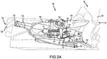
FIGS. 2A and2B illustrate a multi-function lever actuation system in a neutral position, in accordance with various embodiments; -
FIGS. 3A and3B illustrate the multi-function lever actuation system ofFIGS. 2A and2B in a first actuated position, in accordance with various embodiments; and -
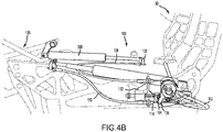
FIGS. 4A and4B illustrate the multi-function lever actuation system ofFIGS. 2A and2B in a second actuated position, in accordance with various embodiments. - The detailed description of exemplary embodiments herein makes reference to the accompanying drawings, which show exemplary embodiments by way of illustration. While these exemplary embodiments are described in sufficient detail to enable those skilled in the art to practice the exemplary embodiments of the disclosure, it should be understood that other embodiments may be realized and that logical changes and adaptations in design and construction may be made in accordance with this disclosure and the teachings herein. Thus, the detailed description herein is presented for purposes of illustration only and not limitation. The steps recited in any of the method or process descriptions may be executed in any order and are not necessarily limited to the order presented.
- Furthermore, any reference to singular includes plural embodiments, and any reference to more than one component or step may include a singular embodiment or step. Also, any reference to attached, fixed, connected or the like may include permanent, removable, temporary, partial, full and/or any other possible attachment option. Additionally, any reference to without contact (or similar phrases) may also include reduced contact or minimal contact. Surface shading lines may be used throughout the figures to denote different parts but not necessarily to denote the same or different materials.
- Referring now to
FIG. 1 , anaircraft interior 10 of anaircraft 20 may includemultiple seat assemblies 30. Each of theseat assemblies 30 may be designed for use in theaircraft 20. For example, theseat assemblies 30 may be oriented all facing forward, as with commercial aircraft, or may be oriented in different directions, as with personal or business aircraft and as shown inFIG. 1 . Each of theseat assemblies 30 may further include a multi-function lever actuation system 100 (or system 100). As will be disclosed in more detail below, the multi-functionlever actuation system 100 may include a control lever (element 102 ofFIG. 2 ) which may control two or more actuated systems (such as a seat recline system and a leg rest system) of theseat assemblies 30. - Referring now to
FIGS. 2A and2B , additional details of the multi-functionlever actuation system 100 are shown. Thesystem 100 may be included as part of theseat assembly 30 or may be provided as a separate component from theseat assembly 30. Thesystem 100 may include acontrol lever 102, arotary component 104 coupled to thecontrol lever 102 and designed to rotate along with thecontrol lever 102, and a bell crank 106 coupled to therotary component 104 at afulcrum 116 and designed to rotate in an opposite direction relative to thecontrol lever 102 and therotary component 104. In that regard and in response to counterclockwise rotation of thecontrol lever 102, therotary component 104 may likewise rotate in the counterclockwise direction and the bell crank 106 may rotate in the clockwise direction. Likewise and in response to clockwise rotation of thecontrol lever 102, therotary component 104 may rotate in the clockwise direction and the bell crank 106 may rotate in the counterclockwise direction. - The
system 100 may further include afirst cable 108 coupled to the control lever 102 (such as via the rotary component 104) and asecond cable 110 likewise coupled to the control lever 102 (such as via the rotary component 104). For example, thefirst cable 108 may be coupled to a top of amain body 138 located at a bottom of therotary component 104, and thesecond cable 110 may be coupled to anarm 136 located at a bottom of therotary component 104. Therotary component 104 may apply tension to thefirst cable 108 in response to rotation of thecontrol lever 102 in a first direction (such as a clockwise direction) and may apply tension to thesecond cable 110 in response to rotation of thecontrol lever 102 in a second direction (such as a counterclockwise direction). - The
system 100 may also include astatic component 112 that remains stationary relative to thecontrol lever 102, therotary component 104, and thebell crank 106. Thesystem 100 may further include aspring 114 coupled to thestatic component 112 and designed to contact therotary component 104 in response to thecontrol lever 102 being in a neutral position (as shown inFIGS. 2A and2B ). Thespring 114 may cause thecontrol lever 102 to return to the neutral position in response to a lack of pressure being applied on thecontrol lever 102. - The
system 100 may be coupled to, and designed to control, a first actuatedsystem 124 and a second actuatedsystem 126. The first actuatedsystem 124 may be a seat recline system designed to control operation of a seat back 130 of theseat assembly 30. The second actuatedsystem 126 may be a leg rest system designed to control operation of aleg rest 128 of theseat assembly 30. - The first actuated
system 124 may include a first controlledcomponent 118, such as a recline lock (element 200 ofFIG. 3A ) and a third controlledcomponent 122, such as a fluid cylinder (element 202 ofFIG. 3A ). In response to the recline lock and the fluid cylinder of the first actuatedsystem 124 being actuated, the seat back 130 may be moved between an upright and a reclined position. - The second actuated
system 126 may include a second controlledcomponent 120, such as a fluid cylinder (element 300 ofFIG. 4A ). In response to the fluid cylinder of the second actuatedsystem 126 being actuated, theleg rest 128 may be moved between a stowed position and an extended position. - The
rotary component 104 may define a first lostmotion slot 132 and a second lostmotion slot 134. Thefirst cable 108 may extend through the first lostmotion slot 132 and thesecond cable 110 may extend through the second lostmotion slot 134. In response to rotation of therotary component 104 in the clockwise direction, therotary component 104 may apply tension to thefirst cable 108 while the second lostmotion slot 134 allows thesecond cable 110 to extend therethrough, failing to apply tension to thesecond cable 110. - Likewise, in response to rotation of the
rotary component 104 in the counterclockwise direction, therotary component 104 may apply pressure to thesecond cable 110 while the first lostmotion slot 132 allows thefirst cable 108 to extend therethrough, failing to apply tension to thefirst cable 108. - Although the
system 100 is shown as utilizing a counterclockwise rotation of thecontrol lever 102 to control the first actuatedsystem 124 and a clockwise rotation of thecontrol lever 102 to control the second actuatedsystem 126, one skilled in the art will realize that this control may be reversed without departing from the scope of the present disclosure. - Referring now to
FIGS. 3A and3B , operation of thesystem 100 to control the first actuated system 124 (corresponding to operation of the seat back 130) is shown. In response to a first stage or amount of rotation of thecontrol lever 102 in the counterclockwise direction, therotary component 104 may likewise rotate along with thecontrol lever 102. The bell crank 106 may rotate in the clockwise direction in response to the counterclockwise rotation of therotary component 104. - In response to a first rotation of the bell crank 106 in the clockwise direction, the bell crank 106 may contact the first controlled
component 118, thus actuating the first controlled component. For example, acontrol arm 204 of the bell crank 106 may apply a downward force on the first controlledcomponent 118. As described above, the first controlledcomponent 118 may include arecline lock 200 designed to unlock a locking mechanism corresponding to the seat back 130. - In response to a second stage or amount of rotation of the
control lever 102 in the counterclockwise direction (corresponding to a continuation of the first rotation), therotary component 104 may apply tension to thesecond cable 110. This tension may transfer through thesecond cable 110 and actuate the third controlledcomponent 122, which may correspond to actuation of thefluid cylinder 202. For example, thesecond cable 110 may actuate alever 206 that is coupled to thefluid cylinder 202, allowing thefluid cylinder 202 to receive fluid (to expand) or expel fluid (to contract). Actuation of thefluid cylinder 202 may facilitate a reclining function of the seat back 130. - Thus, rotation of the
control lever 102 by a first amount unlocks therecline lock 200 and continued rotation of thecontrol lever 102 by a second amount actuates thefluid cylinder 202, allowing the seat back 130 to be reclined. In that regard, the first actuatedsystem 124 may be a two-stage actuated system, actuating only in response to both stages (the first controlledcomponent 118 and the third controlled component 122) being actuated. This may be desirable for control of a seat back 130 to reduce the likelihood of the seat back 130 actuating during takeoff or landing. - In various embodiments, the first controlled
component 118 may operate a separate component than the third controlledcomponent 122. For example, the first controlledcomponent 118 may control a seat back and the third controlledcomponent 122 may control a seat height. - Due to the first lost
motion slot 132 allowing thefirst cable 108 to move therethrough, rotation of thecontrol lever 102 in the counterclockwise direction fails to affect the second actuatedsystem 126. - In various embodiments, the
spring 114 may be coupled to therotary component 104 in such a manner that rotation of therotary component 104 in the counterclockwise direction extends thespring 114, thus causing thespring 114 to apply a pressure to therotary component 104. This pressure may cause therotary component 104, and thus thecontrol lever 102, to return to the neutral position in response to a lack of pressure applied to thecontrol lever 102. - In various embodiments, the
recline lock 200 may be coupled to a spring and thus be spring loaded. In that regard, therecline lock 200 may become spring-loaded in response to rotation of thecontrol lever 102 in the counterclockwise direction and may cause the control lever 102 (via the bell crank 106 and the rotary component) to return to the neutral position in response to a lack of force being applied to thecontrol lever 102. In such embodiments, it may be undesirable to have thespring 114 apply pressure to therotary component 104 in response to rotation of the rotary component in the counterclockwise direction. - Referring now to
FIGS. 4A and4B , operation of thesystem 100 to control the second actuatedsystem 126 corresponding to operation of theleg rest 128 is shown. In response to a rotation of thecontrol lever 102 in the clockwise direction, therotary component 104 may likewise rotate along with thecontrol lever 102. The bell crank 106 may rotate in the counterclockwise direction in response to the clockwise rotation of therotary component 104. Such rotation of the bell crank 106 in the counterclockwise direction may fail to affect operation of theseat assembly 30. - In response to the rotation of the
rotary component 104 in the clockwise direction, therotary component 104 may apply tension to thefirst cable 108. This tension may transfer through thefirst cable 108 and actuate the second controlledcomponent 120, which may correspond to actuation of thefluid cylinder 300. For example, thefirst cable 108 may actuate a lever or other mechanism that allows thefluid cylinder 300 to receive fluid (to expand) or expel fluid (to contract). Actuation of thefluid cylinder 300 may facilitate movement of theleg rest 128. Thus, rotation of thecontrol lever 102 in the clockwise direction actuates thefluid cylinder 300, allowing theleg rest 128 to actuate. - Due to the second lost
motion slot 134 allowing thesecond cable 110 to move therethrough, rotation of thecontrol lever 102 in the clockwise direction fails to affect the first actuatedsystem 124. - In various embodiments, the
spring 114 may be coupled to therotary component 104 in such a manner that rotation of therotary component 104 in the clockwise direction compresses thespring 114, thus causing thespring 114 to apply a pressure to therotary component 104. This pressure may cause therotary component 104, and thus thecontrol lever 102, to return to the neutral position in response to a lack of pressure applied to thecontrol lever 102. - Although the
system 100 has been described as controlling a seat back and a leg rest of a seat assembly, thesystem 100 may similarly be used to control any two or more actuated systems. For example, thecontrol lever 102 may be used to control a seat height adjustment and a seat back, a desk raising system and a desk/backward actuation system, or the like. - Benefits and other advantages have been described herein with regard to specific embodiments. Furthermore, the connecting lines shown in the various figures contained herein are intended to represent exemplary functional relationships and/or physical couplings between the various elements. It should be noted that many alternative or additional functional relationships or physical connections may be present in a practical system. However, the benefits, advantages, and any elements that may cause any benefit or advantage to occur or become more pronounced are not to be construed as critical, required, or essential features or elements of the disclosure. The scope of the disclosure is accordingly to be limited by nothing other than the appended claims, in which reference to an element in the singular is not intended to mean "one and only one" unless explicitly so stated, but rather "one or more." Moreover, where a phrase similar to "at least one of A, B, or C" is used in the claims, it is intended that the phrase be interpreted to mean that A alone may be present in an embodiment, B alone may be present in an embodiment, C alone may be present in an embodiment, or that any combination of the elements A, B and C may be present in a single embodiment; for example, A and B, A and C, B and C, or A and B and C.
- Systems, methods and apparatus are provided herein. In the detailed description herein, references to "various embodiments", "one embodiment", "an embodiment", "an example embodiment", etc., indicate that the embodiment described may include a particular feature, structure, or characteristic, but every embodiment may not necessarily include the particular feature, structure, or characteristic. Moreover, such phrases are not necessarily referring to the same embodiment. Further, when a particular feature, structure, or characteristic is described in connection with an embodiment, it is submitted that it is within the knowledge of one skilled in the art to affect such feature, structure, or characteristic in connection with other embodiments whether or not explicitly described. After reading the description, it will be apparent to one skilled in the relevant art(s) how to implement the disclosure in alternative embodiments.
- Furthermore, no element, component, or method step in the present disclosure is intended to be dedicated to the public regardless of whether the element, component, or method step is explicitly recited in the claims. As used herein, the terms "comprises", "comprising", or any other variation thereof, are intended to cover a non-exclusive inclusion, such that a process, method, article, or apparatus that comprises a list of elements does not include only those elements but may include other elements not expressly listed or inherent to such process, method, article, or apparatus.
Claims (15)
- A multi-function lever actuation system (100), comprising:a control lever (102) having a neutral position and configured to be actuated in a clockwise direction and in a counterclockwise direction;a bell crank (106) coupled to the control lever and configured to rotate in an opposite direction from the control lever and to actuate a first controlled component (118) in response to a first rotation of the control lever in a first direction corresponding to the clockwise direction or the counterclockwise direction; anda first cable (108) coupled to the control lever and configured to actuate a second controlled component (120) in response to a rotation of the control lever in a second direction corresponding to the other of the clockwise direction or the counterclockwise direction.
- The multi-function lever actuation system of claim 1, wherein the control lever defines a first lost motion slot and the first cable is coupled to the control lever via being received by the first lost motion slot such that the first rotation of the control lever in the first direction fails to actuate the first cable.
- The multi-function lever actuation system of claim 1 or 2, further comprising a second cable coupled to the control lever and configured to actuate a third controlled component in response to a second rotation of the control lever in the first direction that is greater than the first rotation.
- The multi-function lever actuation system of claim 3, wherein the first controlled component and the third controlled component are both coupled to a first actuated system such that actuation of the first controlled component unlocks the first actuated system and actuation of the third controlled component facilitates actuation of the first actuated system; optionally wherein the first actuated system is a seat recline system of a seat assembly such that the second rotation of the control lever in the first direction actuates the seat recline system, and the second controlled component is coupled to a second actuated system that corresponds to a leg rest system of the seat assembly such that the rotation of the control lever in the second direction actuates the leg rest system.
- The multi-function lever actuation system of any preceding claim, further comprising a rotary component coupled to the control lever and configured to rotate with the control lever, wherein the second cable is coupled to the control lever via the rotary component.
- The multi-function lever actuation system of claim 5, wherein the rotary component defines a second lost motion slot and the second cable is coupled to the rotary component via being received by the second lost motion slot such that the rotation of the control lever in the second direction fails to actuate the second cable.
- The multi-function lever actuation system of claim 5 or 6, wherein the rotary component is coupled to the bell crank at a fulcrum such that the bell crank rotates in the opposite direction from the rotary component and the control lever; and/or further comprising a static component configured to be in contact with the rotary component in response to the control lever being in the neutral position, and a spring coupled to the static component and configured to resist the rotation of the rotary component in the second direction in order to cause the control lever to return to the neutral position in response to a release of pressure to the control lever.
- A multi-function lever actuation system, comprising:a control lever having a neutral position and configured to be actuated in a clockwise direction and in a counterclockwise direction;a rotary component coupled to the control lever and configured to actuate a first controlled component in response to a first rotation of the control lever in a first direction corresponding to the clockwise direction or the counterclockwise direction; anda first cable coupled to the control lever and configured to actuate a second controlled component in response to a rotation of the control lever in a second direction corresponding to the other of the clockwise direction or the counterclockwise direction.
- The multi-function lever actuation system of claim 8, wherein the control lever defines a first lost motion slot and the first cable is coupled to the control lever via being received by the first lost motion slot such that the first rotation of the control lever in the first direction fails to actuate the first cable.
- The multi-function lever actuation system of claim 8 or 9, further comprising a second cable coupled to the control lever and configured to actuate a third controlled component in response to a second rotation of the control lever in the first direction that is greater than the first rotation.
- The multi-function lever actuation system of claim 10, wherein the first controlled component and the third controlled component are both coupled to a first actuated system such that actuation of the first controlled component unlocks the first actuated system and actuation of the third controlled component facilitates actuation of the first actuated system; optionally wherein the first actuated system is a seat recline system of a seat assembly such that the second rotation of the control lever in the first direction actuates the seat recline system, and the second controlled component is coupled to a second actuated system that corresponds to a leg rest system of the seat assembly such that the rotation of the control lever in the second direction actuates the leg rest system.
- The multi-function lever actuation system of claim 10 or 11, wherein the second cable is coupled to the control lever via the rotary component; optionally wherein the rotary component defines a second lost motion slot and the second cable is coupled to the rotary component via being received by the second lost motion slot such that the rotation of the control lever in the second direction fails to actuate the second cable.
- The multi-function lever actuation system of claim 10, 11 or 12, further comprising a bell crank coupled to the rotary component at a fulcrum such that the bell crank rotates in an opposite direction from the rotary component and the control lever, wherein the rotary component is configured to actuate the first controlled component via the rotation of the bell crank; and/or further comprising a static component configured to be in contact with the rotary component in response to the control lever being in the neutral position, and a spring coupled to the static component and configured to resist the rotation of the rotary component in the second direction in order to cause the control lever to return to the neutral position in response to a release of pressure to the control lever.
- A multi-function lever actuation system, comprising:a control lever (102) having a neutral position and configured to be actuated in a clockwise direction and in a counterclockwise direction;a rotary component (104) coupled to the control lever and configured to rotate with the control lever;a bell crank (106) coupled to the rotary component at a fulcrum and configured to rotate in an opposite direction from the control lever and the rotary component in order to actuate a first controlled component (118) in response to a first rotation of the control lever in a first direction corresponding to the clockwise direction or the counterclockwise direction;a first cable (108) coupled to the control lever and configured to actuate a second controlled component (120) in response to a rotation of the control lever in a second direction corresponding to the other of the clockwise direction or the counterclockwise direction; anda second cable (110) coupled to the rotary component and configured to actuate a third controlled component (122) in response to a second rotation of the control lever in the first direction that is greater than the first rotation.
- The multi-function lever actuation system of claim 14, wherein:the first controlled component and the third controlled component are both coupled to a first actuated system such that actuation of the first controlled component unlocks the first actuated system and actuation of the third controlled component facilitates actuation of the first actuated system; andthe second controlled component is coupled to a second actuated system such that actuation of the second controlled component facilitates actuation of the second actuated system.
Applications Claiming Priority (1)
| Application Number | Priority Date | Filing Date | Title |
|---|---|---|---|
| US16/388,497 US10940949B2 (en) | 2019-04-18 | 2019-04-18 | Short multiple function rotary actuator lever |
Publications (2)
| Publication Number | Publication Date |
|---|---|
| EP3725685A1 true EP3725685A1 (en) | 2020-10-21 |
| EP3725685B1 EP3725685B1 (en) | 2022-01-26 |
Family
ID=69063592
Family Applications (1)
| Application Number | Title | Priority Date | Filing Date |
|---|---|---|---|
| EP19213468.2A Active EP3725685B1 (en) | 2019-04-18 | 2019-12-04 | Short multiple function rotary actuator lever |
Country Status (2)
| Country | Link |
|---|---|
| US (1) | US10940949B2 (en) |
| EP (1) | EP3725685B1 (en) |
Families Citing this family (1)
| Publication number | Priority date | Publication date | Assignee | Title |
|---|---|---|---|---|
| JP6912607B2 (en) * | 2018-02-09 | 2021-08-04 | 株式会社オートネットワーク技術研究所 | Armrest |
Citations (6)
| Publication number | Priority date | Publication date | Assignee | Title |
|---|---|---|---|---|
| GB559817A (en) * | 1942-09-01 | 1944-03-07 | James Henry Pratt | Improvements in braking systems for use in conjunction with the landing wheels of aircraft |
| US2453869A (en) * | 1941-08-01 | 1948-11-16 | Hughes Tool Co | Bomb-carrying apparatus for aircraft |
| US2660383A (en) * | 1949-02-21 | 1953-11-24 | Northrop Aircraft Inc | Elevon stick control |
| US20090026825A1 (en) * | 2006-01-27 | 2009-01-29 | Takahiro Ishijima | Seat |
| KR20090072204A (en) * | 2007-12-28 | 2009-07-02 | 주식회사다스 | Seat back reclining and seat cushion sliding adjustment |
| JP2009261285A (en) * | 2008-04-23 | 2009-11-12 | Kubota Corp | Riding work vehicle |
Family Cites Families (15)
| Publication number | Priority date | Publication date | Assignee | Title |
|---|---|---|---|---|
| US2669284A (en) * | 1948-05-17 | 1954-02-16 | Cons Vultee Aircraft Corp | Adjustable vehicle seat |
| US2892358A (en) * | 1955-12-05 | 1959-06-30 | Fuller Mfg Co | Multi speed, lever controlled transmission |
| US3188044A (en) * | 1963-09-03 | 1965-06-08 | Gen Motors Corp | Vehicle seat adjuster |
| US3301084A (en) * | 1964-11-23 | 1967-01-31 | Kiekhaefer Corp | Single lever control system |
| US3537328A (en) * | 1969-05-28 | 1970-11-03 | Deere & Co | Combined hand lever and foot pedals for controlling vehicle speed and direction |
| US5197780A (en) | 1991-02-20 | 1993-03-30 | Fisher Dynamics Corporation | Transmission device for cable control of lumbar support mechanism |
| US5909923A (en) * | 1997-10-24 | 1999-06-08 | Steelcase Inc. | Chair with novel pivot mounts and method of assembly |
| US6139104A (en) | 1999-01-29 | 2000-10-31 | Johnson Controls Technology Company | Multiple function seat back adjusting mechanism |
| JP4182983B2 (en) * | 2006-01-27 | 2008-11-19 | トヨタ自動車株式会社 | Sheet |
| US7866751B2 (en) | 2007-10-02 | 2011-01-11 | Brunswick Corporation | Apparatus and methods to integrally form lever operated cables with vehicle seats |
| USD697726S1 (en) * | 2012-09-20 | 2014-01-21 | Steelcase Inc. | Chair |
| US9758059B2 (en) * | 2014-08-26 | 2017-09-12 | Ami Industries, Inc. | Multi-function seat actuator |
| US9290272B1 (en) * | 2015-02-10 | 2016-03-22 | Ami Industries, Inc. | Decoupled aircraft seat actuator |
| US9725176B2 (en) * | 2015-02-10 | 2017-08-08 | Ami Industries, Inc. | Dual-function seat actuator |
| US10266270B2 (en) | 2015-08-21 | 2019-04-23 | Textron Innovations, Inc. | Locking system for articulating aircraft seat |
-
2019
- 2019-04-18 US US16/388,497 patent/US10940949B2/en active Active
- 2019-12-04 EP EP19213468.2A patent/EP3725685B1/en active Active
Patent Citations (6)
| Publication number | Priority date | Publication date | Assignee | Title |
|---|---|---|---|---|
| US2453869A (en) * | 1941-08-01 | 1948-11-16 | Hughes Tool Co | Bomb-carrying apparatus for aircraft |
| GB559817A (en) * | 1942-09-01 | 1944-03-07 | James Henry Pratt | Improvements in braking systems for use in conjunction with the landing wheels of aircraft |
| US2660383A (en) * | 1949-02-21 | 1953-11-24 | Northrop Aircraft Inc | Elevon stick control |
| US20090026825A1 (en) * | 2006-01-27 | 2009-01-29 | Takahiro Ishijima | Seat |
| KR20090072204A (en) * | 2007-12-28 | 2009-07-02 | 주식회사다스 | Seat back reclining and seat cushion sliding adjustment |
| JP2009261285A (en) * | 2008-04-23 | 2009-11-12 | Kubota Corp | Riding work vehicle |
Also Published As
| Publication number | Publication date |
|---|---|
| US10940949B2 (en) | 2021-03-09 |
| US20200331612A1 (en) | 2020-10-22 |
| EP3725685B1 (en) | 2022-01-26 |
Similar Documents
| Publication | Publication Date | Title |
|---|---|---|
| US10076975B2 (en) | Brake release for aircraft seat | |
| US10011197B2 (en) | Dual-function seat actuator | |
| US8690251B2 (en) | Easy-entry seat-back release system for vehicle seat | |
| US8544791B2 (en) | Pedal operated apparatus for controlling an aircraft nose wheel steering system | |
| US7182402B1 (en) | Seat recline control override | |
| US20120217781A1 (en) | Master/slave easy entry recliner | |
| WO1996020848A1 (en) | Seat locking mechanism and seat incorporating same | |
| US10093201B2 (en) | Adjuster with storage function of a vehicle seat backrest | |
| US10329020B2 (en) | Integrated deployable leg rest for reclining passenger seats | |
| US10940949B2 (en) | Short multiple function rotary actuator lever | |
| US4573649A (en) | Integrated alternate gear extension and ground-crew door opening/closing system for an aircraft | |
| US9744881B2 (en) | System and apparatus for decoupling an electro-mechanical actuator from a portion of a linkage | |
| US9290272B1 (en) | Decoupled aircraft seat actuator | |
| WO1987002642A1 (en) | Deployment-retraction apparatus for aircraft turbines | |
| US11021239B2 (en) | Shock strut shrinking system | |
| CN114056575B (en) | Translating, locking and rotating leg rests | |
| US12617524B2 (en) | Uplock unlock electro-hydrostatic actuator | |
| EP4711274A1 (en) | Seat armrest locking mechanism | |
| EP1399331A1 (en) | Disc recliner dump lock |
Legal Events
| Date | Code | Title | Description |
|---|---|---|---|
| PUAI | Public reference made under article 153(3) epc to a published international application that has entered the european phase |
Free format text: ORIGINAL CODE: 0009012 |
|
| STAA | Information on the status of an ep patent application or granted ep patent |
Free format text: STATUS: THE APPLICATION HAS BEEN PUBLISHED |
|
| AK | Designated contracting states |
Kind code of ref document: A1 Designated state(s): AL AT BE BG CH CY CZ DE DK EE ES FI FR GB GR HR HU IE IS IT LI LT LU LV MC MK MT NL NO PL PT RO RS SE SI SK SM TR |
|
| AX | Request for extension of the european patent |
Extension state: BA ME |
|
| STAA | Information on the status of an ep patent application or granted ep patent |
Free format text: STATUS: REQUEST FOR EXAMINATION WAS MADE |
|
| 17P | Request for examination filed |
Effective date: 20210119 |
|
| RBV | Designated contracting states (corrected) |
Designated state(s): AL AT BE BG CH CY CZ DE DK EE ES FI FR GB GR HR HU IE IS IT LI LT LU LV MC MK MT NL NO PL PT RO RS SE SI SK SM TR |
|
| REG | Reference to a national code |
Ref country code: DE Ref legal event code: R079 Ref document number: 602019011203 Country of ref document: DE Free format text: PREVIOUS MAIN CLASS: B64D0011060000 Ipc: B60N0002020000 |
|
| GRAP | Despatch of communication of intention to grant a patent |
Free format text: ORIGINAL CODE: EPIDOSNIGR1 |
|
| STAA | Information on the status of an ep patent application or granted ep patent |
Free format text: STATUS: GRANT OF PATENT IS INTENDED |
|
| RIC1 | Information provided on ipc code assigned before grant |
Ipc: B60N 2/02 20060101AFI20210607BHEP Ipc: B64D 11/06 20060101ALN20210607BHEP |
|
| RIC1 | Information provided on ipc code assigned before grant |
Ipc: B60N 2/02 20060101AFI20210614BHEP Ipc: B64D 11/06 20060101ALN20210614BHEP |
|
| RIC1 | Information provided on ipc code assigned before grant |
Ipc: B60N 2/02 20060101AFI20210623BHEP Ipc: B64D 11/06 20060101ALN20210623BHEP |
|
| INTG | Intention to grant announced |
Effective date: 20210714 |
|
| GRAS | Grant fee paid |
Free format text: ORIGINAL CODE: EPIDOSNIGR3 |
|
| GRAA | (expected) grant |
Free format text: ORIGINAL CODE: 0009210 |
|
| STAA | Information on the status of an ep patent application or granted ep patent |
Free format text: STATUS: THE PATENT HAS BEEN GRANTED |
|
| AK | Designated contracting states |
Kind code of ref document: B1 Designated state(s): AL AT BE BG CH CY CZ DE DK EE ES FI FR GB GR HR HU IE IS IT LI LT LU LV MC MK MT NL NO PL PT RO RS SE SI SK SM TR |
|
| REG | Reference to a national code |
Ref country code: GB Ref legal event code: FG4D |
|
| REG | Reference to a national code |
Ref country code: CH Ref legal event code: EP |
|
| REG | Reference to a national code |
Ref country code: AT Ref legal event code: REF Ref document number: 1465023 Country of ref document: AT Kind code of ref document: T Effective date: 20220215 |
|
| REG | Reference to a national code |
Ref country code: IE Ref legal event code: FG4D |
|
| REG | Reference to a national code |
Ref country code: DE Ref legal event code: R096 Ref document number: 602019011203 Country of ref document: DE |
|
| REG | Reference to a national code |
Ref country code: LT Ref legal event code: MG9D |
|
| REG | Reference to a national code |
Ref country code: NL Ref legal event code: MP Effective date: 20220126 |
|
| PG25 | Lapsed in a contracting state [announced via postgrant information from national office to epo] |
Ref country code: NL Free format text: LAPSE BECAUSE OF FAILURE TO SUBMIT A TRANSLATION OF THE DESCRIPTION OR TO PAY THE FEE WITHIN THE PRESCRIBED TIME-LIMIT Effective date: 20220126 |
|
| PG25 | Lapsed in a contracting state [announced via postgrant information from national office to epo] |
Ref country code: SE Free format text: LAPSE BECAUSE OF FAILURE TO SUBMIT A TRANSLATION OF THE DESCRIPTION OR TO PAY THE FEE WITHIN THE PRESCRIBED TIME-LIMIT Effective date: 20220126 Ref country code: RS Free format text: LAPSE BECAUSE OF FAILURE TO SUBMIT A TRANSLATION OF THE DESCRIPTION OR TO PAY THE FEE WITHIN THE PRESCRIBED TIME-LIMIT Effective date: 20220126 Ref country code: PT Free format text: LAPSE BECAUSE OF FAILURE TO SUBMIT A TRANSLATION OF THE DESCRIPTION OR TO PAY THE FEE WITHIN THE PRESCRIBED TIME-LIMIT Effective date: 20220526 Ref country code: NO Free format text: LAPSE BECAUSE OF FAILURE TO SUBMIT A TRANSLATION OF THE DESCRIPTION OR TO PAY THE FEE WITHIN THE PRESCRIBED TIME-LIMIT Effective date: 20220426 Ref country code: LT Free format text: LAPSE BECAUSE OF FAILURE TO SUBMIT A TRANSLATION OF THE DESCRIPTION OR TO PAY THE FEE WITHIN THE PRESCRIBED TIME-LIMIT Effective date: 20220126 Ref country code: HR Free format text: LAPSE BECAUSE OF FAILURE TO SUBMIT A TRANSLATION OF THE DESCRIPTION OR TO PAY THE FEE WITHIN THE PRESCRIBED TIME-LIMIT Effective date: 20220126 Ref country code: ES Free format text: LAPSE BECAUSE OF FAILURE TO SUBMIT A TRANSLATION OF THE DESCRIPTION OR TO PAY THE FEE WITHIN THE PRESCRIBED TIME-LIMIT Effective date: 20220126 Ref country code: BG Free format text: LAPSE BECAUSE OF FAILURE TO SUBMIT A TRANSLATION OF THE DESCRIPTION OR TO PAY THE FEE WITHIN THE PRESCRIBED TIME-LIMIT Effective date: 20220426 |
|
| PG25 | Lapsed in a contracting state [announced via postgrant information from national office to epo] |
Ref country code: PL Free format text: LAPSE BECAUSE OF FAILURE TO SUBMIT A TRANSLATION OF THE DESCRIPTION OR TO PAY THE FEE WITHIN THE PRESCRIBED TIME-LIMIT Effective date: 20220126 Ref country code: LV Free format text: LAPSE BECAUSE OF FAILURE TO SUBMIT A TRANSLATION OF THE DESCRIPTION OR TO PAY THE FEE WITHIN THE PRESCRIBED TIME-LIMIT Effective date: 20220126 Ref country code: GR Free format text: LAPSE BECAUSE OF FAILURE TO SUBMIT A TRANSLATION OF THE DESCRIPTION OR TO PAY THE FEE WITHIN THE PRESCRIBED TIME-LIMIT Effective date: 20220427 Ref country code: FI Free format text: LAPSE BECAUSE OF FAILURE TO SUBMIT A TRANSLATION OF THE DESCRIPTION OR TO PAY THE FEE WITHIN THE PRESCRIBED TIME-LIMIT Effective date: 20220126 |
|
| PG25 | Lapsed in a contracting state [announced via postgrant information from national office to epo] |
Ref country code: IS Free format text: LAPSE BECAUSE OF FAILURE TO SUBMIT A TRANSLATION OF THE DESCRIPTION OR TO PAY THE FEE WITHIN THE PRESCRIBED TIME-LIMIT Effective date: 20220526 |
|
| REG | Reference to a national code |
Ref country code: DE Ref legal event code: R097 Ref document number: 602019011203 Country of ref document: DE |
|
| PG25 | Lapsed in a contracting state [announced via postgrant information from national office to epo] |
Ref country code: SM Free format text: LAPSE BECAUSE OF FAILURE TO SUBMIT A TRANSLATION OF THE DESCRIPTION OR TO PAY THE FEE WITHIN THE PRESCRIBED TIME-LIMIT Effective date: 20220126 Ref country code: SK Free format text: LAPSE BECAUSE OF FAILURE TO SUBMIT A TRANSLATION OF THE DESCRIPTION OR TO PAY THE FEE WITHIN THE PRESCRIBED TIME-LIMIT Effective date: 20220126 Ref country code: RO Free format text: LAPSE BECAUSE OF FAILURE TO SUBMIT A TRANSLATION OF THE DESCRIPTION OR TO PAY THE FEE WITHIN THE PRESCRIBED TIME-LIMIT Effective date: 20220126 Ref country code: EE Free format text: LAPSE BECAUSE OF FAILURE TO SUBMIT A TRANSLATION OF THE DESCRIPTION OR TO PAY THE FEE WITHIN THE PRESCRIBED TIME-LIMIT Effective date: 20220126 Ref country code: DK Free format text: LAPSE BECAUSE OF FAILURE TO SUBMIT A TRANSLATION OF THE DESCRIPTION OR TO PAY THE FEE WITHIN THE PRESCRIBED TIME-LIMIT Effective date: 20220126 Ref country code: CZ Free format text: LAPSE BECAUSE OF FAILURE TO SUBMIT A TRANSLATION OF THE DESCRIPTION OR TO PAY THE FEE WITHIN THE PRESCRIBED TIME-LIMIT Effective date: 20220126 |
|
| PG25 | Lapsed in a contracting state [announced via postgrant information from national office to epo] |
Ref country code: AL Free format text: LAPSE BECAUSE OF FAILURE TO SUBMIT A TRANSLATION OF THE DESCRIPTION OR TO PAY THE FEE WITHIN THE PRESCRIBED TIME-LIMIT Effective date: 20220126 |
|
| PLBE | No opposition filed within time limit |
Free format text: ORIGINAL CODE: 0009261 |
|
| STAA | Information on the status of an ep patent application or granted ep patent |
Free format text: STATUS: NO OPPOSITION FILED WITHIN TIME LIMIT |
|
| 26N | No opposition filed |
Effective date: 20221027 |
|
| PG25 | Lapsed in a contracting state [announced via postgrant information from national office to epo] |
Ref country code: SI Free format text: LAPSE BECAUSE OF FAILURE TO SUBMIT A TRANSLATION OF THE DESCRIPTION OR TO PAY THE FEE WITHIN THE PRESCRIBED TIME-LIMIT Effective date: 20220126 |
|
| P01 | Opt-out of the competence of the unified patent court (upc) registered |
Effective date: 20230521 |
|
| REG | Reference to a national code |
Ref country code: DE Ref legal event code: R119 Ref document number: 602019011203 Country of ref document: DE |
|
| PG25 | Lapsed in a contracting state [announced via postgrant information from national office to epo] |
Ref country code: IT Free format text: LAPSE BECAUSE OF FAILURE TO SUBMIT A TRANSLATION OF THE DESCRIPTION OR TO PAY THE FEE WITHIN THE PRESCRIBED TIME-LIMIT Effective date: 20220126 |
|
| REG | Reference to a national code |
Ref country code: BE Ref legal event code: MM Effective date: 20221231 |
|
| PG25 | Lapsed in a contracting state [announced via postgrant information from national office to epo] |
Ref country code: LU Free format text: LAPSE BECAUSE OF NON-PAYMENT OF DUE FEES Effective date: 20221204 |
|
| PG25 | Lapsed in a contracting state [announced via postgrant information from national office to epo] |
Ref country code: IE Free format text: LAPSE BECAUSE OF NON-PAYMENT OF DUE FEES Effective date: 20221204 Ref country code: DE Free format text: LAPSE BECAUSE OF NON-PAYMENT OF DUE FEES Effective date: 20230701 |
|
| PG25 | Lapsed in a contracting state [announced via postgrant information from national office to epo] |
Ref country code: BE Free format text: LAPSE BECAUSE OF NON-PAYMENT OF DUE FEES Effective date: 20221231 |
|
| REG | Reference to a national code |
Ref country code: AT Ref legal event code: UEP Ref document number: 1465023 Country of ref document: AT Kind code of ref document: T Effective date: 20220126 |
|
| PG25 | Lapsed in a contracting state [announced via postgrant information from national office to epo] |
Ref country code: CY Free format text: LAPSE BECAUSE OF FAILURE TO SUBMIT A TRANSLATION OF THE DESCRIPTION OR TO PAY THE FEE WITHIN THE PRESCRIBED TIME-LIMIT Effective date: 20220126 |
|
| PG25 | Lapsed in a contracting state [announced via postgrant information from national office to epo] |
Ref country code: MK Free format text: LAPSE BECAUSE OF FAILURE TO SUBMIT A TRANSLATION OF THE DESCRIPTION OR TO PAY THE FEE WITHIN THE PRESCRIBED TIME-LIMIT Effective date: 20220126 Ref country code: HU Free format text: LAPSE BECAUSE OF FAILURE TO SUBMIT A TRANSLATION OF THE DESCRIPTION OR TO PAY THE FEE WITHIN THE PRESCRIBED TIME-LIMIT; INVALID AB INITIO Effective date: 20191204 |
|
| PG25 | Lapsed in a contracting state [announced via postgrant information from national office to epo] |
Ref country code: MC Free format text: LAPSE BECAUSE OF FAILURE TO SUBMIT A TRANSLATION OF THE DESCRIPTION OR TO PAY THE FEE WITHIN THE PRESCRIBED TIME-LIMIT Effective date: 20220126 |
|
| PG25 | Lapsed in a contracting state [announced via postgrant information from national office to epo] |
Ref country code: MC Free format text: LAPSE BECAUSE OF FAILURE TO SUBMIT A TRANSLATION OF THE DESCRIPTION OR TO PAY THE FEE WITHIN THE PRESCRIBED TIME-LIMIT Effective date: 20220126 |
|
| GBPC | Gb: european patent ceased through non-payment of renewal fee |
Effective date: 20231204 |
|
| PG25 | Lapsed in a contracting state [announced via postgrant information from national office to epo] |
Ref country code: MT Free format text: LAPSE BECAUSE OF FAILURE TO SUBMIT A TRANSLATION OF THE DESCRIPTION OR TO PAY THE FEE WITHIN THE PRESCRIBED TIME-LIMIT Effective date: 20220126 |
|
| PG25 | Lapsed in a contracting state [announced via postgrant information from national office to epo] |
Ref country code: GB Free format text: LAPSE BECAUSE OF NON-PAYMENT OF DUE FEES Effective date: 20231204 |
|
| PG25 | Lapsed in a contracting state [announced via postgrant information from national office to epo] |
Ref country code: GB Free format text: LAPSE BECAUSE OF NON-PAYMENT OF DUE FEES Effective date: 20231204 |
|
| PG25 | Lapsed in a contracting state [announced via postgrant information from national office to epo] |
Ref country code: TR Free format text: LAPSE BECAUSE OF FAILURE TO SUBMIT A TRANSLATION OF THE DESCRIPTION OR TO PAY THE FEE WITHIN THE PRESCRIBED TIME-LIMIT Effective date: 20220126 |
|
| REG | Reference to a national code |
Ref country code: CH Ref legal event code: U11 Free format text: ST27 STATUS EVENT CODE: U-0-0-U10-U11 (AS PROVIDED BY THE NATIONAL OFFICE) Effective date: 20260101 |
|
| PGFP | Annual fee paid to national office [announced via postgrant information from national office to epo] |
Ref country code: AT Payment date: 20251121 Year of fee payment: 7 |
|
| PGFP | Annual fee paid to national office [announced via postgrant information from national office to epo] |
Ref country code: FR Payment date: 20251120 Year of fee payment: 7 |
|
| PGFP | Annual fee paid to national office [announced via postgrant information from national office to epo] |
Ref country code: CH Payment date: 20260101 Year of fee payment: 7 |