EP3725646A1 - Vehicle rear body structure, and vehicle - Google Patents
Vehicle rear body structure, and vehicle Download PDFInfo
- Publication number
- EP3725646A1 EP3725646A1 EP20161821.2A EP20161821A EP3725646A1 EP 3725646 A1 EP3725646 A1 EP 3725646A1 EP 20161821 A EP20161821 A EP 20161821A EP 3725646 A1 EP3725646 A1 EP 3725646A1
- Authority
- EP
- European Patent Office
- Prior art keywords
- section
- vehicle
- ridgeline
- wheel house
- body structure
- Prior art date
- Legal status (The legal status is an assumption and is not a legal conclusion. Google has not performed a legal analysis and makes no representation as to the accuracy of the status listed.)
- Granted
Links
Images




Classifications
-
- B—PERFORMING OPERATIONS; TRANSPORTING
- B62—LAND VEHICLES FOR TRAVELLING OTHERWISE THAN ON RAILS
- B62D—MOTOR VEHICLES; TRAILERS
- B62D25/00—Superstructure or monocoque structure sub-units; Parts or details thereof not otherwise provided for
- B62D25/02—Side panels
-
- B—PERFORMING OPERATIONS; TRANSPORTING
- B62—LAND VEHICLES FOR TRAVELLING OTHERWISE THAN ON RAILS
- B62D—MOTOR VEHICLES; TRAILERS
- B62D25/00—Superstructure or monocoque structure sub-units; Parts or details thereof not otherwise provided for
- B62D25/08—Front or rear portions
- B62D25/16—Mud-guards or wings; Wheel cover panels
- B62D25/18—Parts or details thereof, e.g. mudguard flaps
-
- B—PERFORMING OPERATIONS; TRANSPORTING
- B62—LAND VEHICLES FOR TRAVELLING OTHERWISE THAN ON RAILS
- B62D—MOTOR VEHICLES; TRAILERS
- B62D25/00—Superstructure or monocoque structure sub-units; Parts or details thereof not otherwise provided for
- B62D25/08—Front or rear portions
- B62D25/16—Mud-guards or wings; Wheel cover panels
-
- B—PERFORMING OPERATIONS; TRANSPORTING
- B62—LAND VEHICLES FOR TRAVELLING OTHERWISE THAN ON RAILS
- B62D—MOTOR VEHICLES; TRAILERS
- B62D25/00—Superstructure or monocoque structure sub-units; Parts or details thereof not otherwise provided for
- B62D25/04—Door pillars ; windshield pillars
-
- B—PERFORMING OPERATIONS; TRANSPORTING
- B62—LAND VEHICLES FOR TRAVELLING OTHERWISE THAN ON RAILS
- B62D—MOTOR VEHICLES; TRAILERS
- B62D25/00—Superstructure or monocoque structure sub-units; Parts or details thereof not otherwise provided for
- B62D25/08—Front or rear portions
- B62D25/087—Luggage compartments
-
- B—PERFORMING OPERATIONS; TRANSPORTING
- B62—LAND VEHICLES FOR TRAVELLING OTHERWISE THAN ON RAILS
- B62D—MOTOR VEHICLES; TRAILERS
- B62D25/00—Superstructure or monocoque structure sub-units; Parts or details thereof not otherwise provided for
- B62D25/08—Front or rear portions
- B62D25/088—Details of structures as upper supports for springs or dampers
-
- B—PERFORMING OPERATIONS; TRANSPORTING
- B62—LAND VEHICLES FOR TRAVELLING OTHERWISE THAN ON RAILS
- B62D—MOTOR VEHICLES; TRAILERS
- B62D25/00—Superstructure or monocoque structure sub-units; Parts or details thereof not otherwise provided for
- B62D25/20—Floors or bottom sub-units
- B62D25/2009—Floors or bottom sub-units in connection with other superstructure subunits
- B62D25/2027—Floors or bottom sub-units in connection with other superstructure subunits the subunits being rear structures
Definitions
- the present invention relates to a vehicle rear body structure and a vehicle.
- the present invention particularly relates to a vehicle rear body structure that is provided with a wheel house having a wheel house outer and a wheel house inner located on a cabin side from the wheel house outer.
- a damper attachment section attached to an upper end portion of a suspension damper for supporting the upper end portion of the suspension damper receives vibrations and a load from a suspension, and thus rigidity of a portion around a wheel house provided in adjacent to the damper attachment section is increased.
- Patent document 1 a configuration to reinforce the wheel house from both sides in a vehicle width direction by providing a reinforcement to each of a wheel house outer and a wheel house inner is disclosed.
- provision of the reinforcement on each of the sides of the wheel house in the vehicle width direction is advantageous in terms of improved rigidity, provision of the reinforcement also leads to an increase in body weight (number of components).
- the present invention has been made in view of such a problem and therefore has a purpose of improving rigidity of a portion around a wheel house while suppressing an increase in body weight (number of components) as much as possible.
- the present invention particularly relates to a vehicle rear body structure provided with a wheel house that includes a wheel house outer in a bulged shape to a cabin outer side, and a wheel house inner located on a cabin side from the wheel house outer.
- the wheel house inner is provided with an inner-side reinforcement that extends in a vertical direction, in the wheel house outer, a bulged section that is formed to be bulged to the cabin outer side includes a wheel arch-shaped section that is formed in an arch shape to cover a rear wheel from above when seen in a vehicle side view.
- the wheel house outer is formed with a ridgeline section that extends upward above the wheel arch-shaped section along a bulged shape of the bulged section to the cabin outer side and at least a portion of which overlaps the inner-side reinforcement when seen in the vehicle side view.
- the portion of the wheel house outer which overlaps the inner-side reinforcement when seen in the vehicle side view, is reinforced by the ridgeline section formed by the bulged shape of the bulged section.
- an upward extending section (a shelf section) that is bulged to the cabin outer side is provided to extend upward from the wheel arch-shaped section.
- the ridgeline section is formed along a bulged shape of the upward extending section to the cabin outer side.
- a damper attachment section to which an upper end portion of a suspension damper is attached for support is provided in a rear side frame provided on the cabin side and in a lower portion of the wheel house.
- the inner-side reinforcement extends upward from the damper attachment section provided in the rear side frame.
- the ridgeline section of the wheel house outer extends upward across the wheel arch-shaped section. Further particularly, the ridgeline section of the wheel house outer extends upward across the wheel arch-shaped section from a height of the rear side frame to the upward extending section.
- the ridgeline section can suppress deformation of the inner-side reinforcement, which is caused by an external force applied to the body side from the suspension damper via the damper attachment section.
- a door opening rear edge reinforcing member is joined to the upward extending section, the door opening rear edge reinforcing member extending along a rear edge of a door opening provided in a body side portion and used for seating on and/or leaving from a rear seat.
- the ridgeline section extends to the door opening rear edge reinforcing member and the inner-side reinforcement, which is provided on a vehicle rear side from the door opening rear edge reinforcing member.
- a rear header that extends in a vehicle width direction is provided on a vehicle front side and a vehicle upper side from the inner-side reinforcement.
- a closed cross-sectional structure that extends rearward from the rear header and is lowered to the rear is provided above the wheel house.
- an upper end of the inner-side reinforcement is joined to a portion, which is separated rearward from a joined section with the rear header, in the closed cross-sectional structure.
- the ridgeline section extends in the vertical direction at a position that is separated rearward in the vehicle from the inner-side reinforcement.
- the ridgeline section extends upward at the position separated from the inner-side reinforcement in a vehicle front-rear direction.
- the ridgeline section can further effectively suppress the deformation of the closed cross-sectional structure with the rear header being the point of origin when seen in the vehicle side view and when seen in the vehicle rear view.
- the upward extending section is provided with a plurality of the ridgeline sections, each of which extends in the vertical direction.
- a vehicle includes the above vehicle rear body structure.
- an arrow F indicates a vehicle front direction
- an arrow R indicates a vehicle right direction
- an arrow L indicates a vehicle left direction
- an arrow U indicates a vehicle up direction
- an arrow out indicates a cabin outer side (an outer side in a vehicle width direction)
- an arrow in indicates a cabin side (an inner side in the vehicle width direction).
- a vehicle rear body structure in this embodiment is substantially and bilaterally symmetrical. Thus, a description will be centered on a configuration on a right side of the vehicle.
- an outer panel as a body outer plate is not illustrated unless otherwise particularly noted.
- a reinforcement will be abbreviated as a rein.
- the vehicle in this embodiment is an automobile of a door hatchback type, includes a rear gate opening 1 (see Fig. 5 ), which is opened rearward from a trunk or a boot as a rear section provided in a body rear portion, in the body rear portion.
- the rear gate opening 1 includes a rear gate of a flip-open type (not illustrated).
- a rear seat pan 2 on which rear seats (not illustrated) are placed, and a rear floor panel 3 for forming the trunk are provided.
- rear side frames 4 On both sides of these rear seat pan 2 and the rear floor panel 3, rear side frames 4, each of which extends in a vehicle front-rear direction, are provided.
- a cross member 5 that extends in the vehicle width direction is particularly provided.
- the rear side frame 4 particularly includes: a rear side frame upper 4a (see Fig. 2 and Fig. 4 ) having a hat-shaped cross section that is opened downward and is projected upward; and a rear side frame lower 4b (see Fig. 4 ) having a hat-shaped cross section that is opened upward and is projected downward. These constitutes a closed cross section 4s that extends in the vehicle front-rear direction therein. Inner edges in the vehicle width direction of the rear side frames 4 on both of the sides hold and fix outer edges in the vehicle width direction of the rear seat pan 2 and the rear floor panel 3 therebetween.
- the rear side frame 4 extends in the vehicle front-rear direction from a rear end of the rear floor panel 3 and passes the wheel house 30.
- a front end portion of the rear side frame 4 is connected to a rear portion of a side sill 6 (not illustrated).
- a damper attachment section 7 to which an upper end portion of an unillustrated rear suspension damper (hereinafter abbreviated as a "damper") is attached for support is particularly provided at a position that is an intermediate position in the vehicle front-rear direction of the rear side frame 4 (a position corresponding to an unillustrated rear suspension) and that corresponds to the cabin side of the wheel house 30, which will be described later.
- a damper an unillustrated rear suspension damper
- a reinforcing member 8 that reinforces a portion around the damper attachment section 7 is particularly provided in an upper portion of the rear side frame 4.
- the reinforcing member 8 is particularly shaped by aluminum die-casting or the like, and is provided to cover the portion around the damper attachment section 7 from above while extending between the upper portion of the rear side frame 4 and the wheel house 30.
- the damper attachment section 7 is particularly configured to include: a damper insertion hole 7a through which the damper is inserted; and damper fastening sections 7b provided on both front and rear sides of the damper insertion hole 7a to fasten and fix the damper to the rear side frame 4 and the reinforcing member 8.
- damper insertion hole 7a and the damper fastening sections 7b on the front and rear sides has portions that respectively correspond to the rear side frame 4 and the reinforcing member 8 and thus perforated in a vertical direction.
- the reinforcing member 8 is particularly formed such that an upper surface thereof is one-step higher than an upper surface of the rear side frame 4. On the upper surface of the rear side frame 4, a circumferential edge of the damper fastening section 7b on each of the front and rear sides is recessed downward.
- a rear pillar 11 As illustrated in Fig. 1 to Fig. 3 , in the side portion of the rear body in this embodiment is particularly provided with a rear pillar 11, a side inner panel 12, an intermediate pillar 13, first and second inner-side reins 14, 15 (see Fig. 2 ), the wheel house 30, and first and second door opening rear edge reinforcing members 16, 17 (a first door opening rear edge reinforcing member 16 and a second door opening rear edge reinforcing member 17).
- the rear pillar 11 extends downward and rearward from a side on each of right and left sides of the rear gate opening 1, and a closed cross section 11s (see Fig. 6 ) that extends along an extending direction of the rear pillar 11 is defined therein.
- the rear pillar 11 which extends in the vehicle front-rear direction (the vertical direction) in the body rear portion, has an upper end that is joined to an outer end in the vehicle width direction of a rear header 18 extending in the vehicle width direction along an upper side of the rear gate opening 1 and to a rear end of a roof side rail 21 extending along the vehicle front-rear direction on each side of a roof section.
- Such a joined portion will hereinafter be referred to as a "joined section C".
- a lower end portion of the rear pillar 11 is particularly joined to an outer end in the vehicle width direction of a rear end member 22 that extends in the vehicle width direction along a lower edge of the rear gate opening 1 (see Fig. 2 and Fig. 4 ).
- the side inner panel 12 is particularly a panel that forms a trunk side wall.
- a lower portion of the side inner panel 12 is disposed up to a circumferential edge (mainly an upper portion and a front portion) of the wheel house 30 on the side of the body rear portion except for a lower portion of the circumferential edge in a manner to be held between a wheel house inner 31 and a wheel house outer 32, which will be described later.
- a portion of the side inner panel 12 above the wheel house 30 is disposed between the rear pillar 11 and the wheel house 30.
- the intermediate pillar 13 particularly corresponds to a front side of an opening 23 for a quarter window.
- An upper end 13a of the intermediate pillar 13 is joined to a rear portion of the roof side rail 21 by spot welding or the like.
- the opening 23 for the quarter window is particularly constructed of the rear portions of the intermediate pillar 13 and the roof side rail 21 and an upper portion of a front edge of the side inner panel 12.
- the first and second inner-side reins 14, 15 are provided on each side in the vehicle front-rear direction.
- Each of the first and second inner-side reins 14, 15 extends upward from a height of the rear side frame 4 to at least a portion of the side inner panel 12 above the wheel house inner 31 in a manner to run across the wheel house inner 31 in the vertical direction (see Fig. 2 ).
- Each of these first and second inner-side reins 14, 15 particularly has a hat-shaped horizontal cross section (a cross section orthogonal to the vertical direction) that is opened to a cabin outer side, and cooperates with the side portion of the vehicle rear portion, that is, the wheel house inner 31 and the side inner panel 12 to define respective one of closed cross sections 14s, 15s that extend in the vertical direction between the wheel house inner 31 and the side inner panel 12 (see Fig. 6 and Fig. 7 ).
- the first inner side rein 14 on the front side extends upward to a substantially lower end portion of the intermediate pillar 13 from an outer end in the vehicle width direction of an upper cross member 5A, which is projected upward (has a hat-shaped cross section opened downward) with respect to the rear floor panel 3, in the cross member 5, so as to run across the wheel house inner 31.
- the second inner side rein 15 on the rear side extends upward across the wheel house inner 31 and the side inner panel 12 from the rear side frame 4, and an upper end of the second inner side rein 15 is joined to an upper portion of the rear pillar 11 (see Fig. 2 ).
- the upper end of the second inner side rein 15 is particularly joined to a portion of the rear pillar 11, which extends while tilting downward to the rear, and the portion is slightly separated rearward from the joined section C (the front end) with the rear header 18.
- a lower portion of each of the first and second inner-side reins 14, 15 is integrally formed with the reinforcing member 8.
- the first and second inner-side reins 14, 15 extend upward from portions of the rear side frame 4 on front and rear sides of the damper attachment section 7 (the front and rear sides of the damper insertion hole 7a) via the reinforcing member 8.
- a position of the lower portion of the second inner side rein 15 matches a position of the damper fastening section 7b on the rear side in the vehicle front-rear direction of the rear side frame 4, and the second inner side rein 15 extends upward in a substantially linear manner from a portion corresponding to the damper fastening section 7b on the rear side (see Fig. 2 ).
- the wheel house 30 is configured that an upper portion of a rear wheel (not illustrated) can be accommodated from a rear side to a front side thereof in the wheel house inner 31, which is bulged to the cabin side (or toward the cabin), and the wheel house outer 32, which is bulged to the cabin outer side (or outward from the cabin).
- Each of the wheel house inner 31 and the wheel house outer 32 is particularly configured to include: a bulged section 33 that is bulged to respective one of the cabin side and the cabin outer side; and a flange 34 that is formed at an outer edge thereof except for a lower edge when seen in the vehicle side view.
- the flanges 34 are joined to each other so as to hold a lower edge of the side inner panel 12 therebetween.
- the bulged section 33 of the wheel house outer 32 is integrally formed with a wheel arch-shaped section 35 and an upward extending section 36 (a shelf section).
- the wheel arch-shaped section 35 is provided in a lower portion including a lower edge of the bulged section 33, and, in an upper portion of the bulged section 33, the upward extending section 36 extends upward from the wheel arch-shaped section 35.
- the wheel house inner 31 is particularly formed to correspond or adapted to the wheel house outer 32 and thus extends upward to the substantially same height as the bulged section 33 (see Fig. 4 ).
- the wheel arch-shaped section 35 is formed in a shape that follows a lower edge of the wheel house outer 32, that is, an arch shape (an arcuate shape) in which an intermediate portion in the vehicle front-rear direction is projected upward when seen in the vehicle side view.
- a front portion of the wheel arch-shaped section 35 is particularly formed to be gradually lowered to the front, and a front lower end thereof is connected to a rear portion of the side sill 6.
- the front portion of the wheel arch-shaped section 35 is particularly formed such that a front edge thereof is located in front of the front edge of the side inner panel 12, so as to form a lower portion of a rear edge 24r of a door opening 24, which is provided on the body side portion and is used for seating on and leaving from the rear seat (see Fig. 1 ).
- the upward extending section 36 particularly extends upward from the wheel arch-shaped section 35, and a lower end portion thereof extends upward from a rear end of the wheel arch-shaped section 35 such that the upward extending section 36 has a width in the vehicle front-rear direction between the rear end and a position slightly in front of an apex (an upper end) of the wheel arch-shaped section 35. That is, the upward extending section 36 is provided across the second inner side rein 15 in the vehicle front-rear direction.
- the bulged section 33 is integrally formed such that internal spaces of the upward extending section 36 and the wheel arch-shaped section 35 provided on upper and lower sides thereof communicate with each other in the vertical direction (see Fig. 4 ) .
- the upward extending section 36 is formed such that a bulged length (a bulged amount) to the cabin outer side of the substantially entire upward extending section 36 except for a rear portion 36r is less than that of the wheel arch-shaped section 35.
- the substantially entire upward extending section 36 except for the rear portion 36r is bulged to have the bulged length that is approximately one half of the bulged length of the wheel arch-shaped section 35.
- a rear portion 35r of the wheel arch-shaped section 35 is bulged such that, as the rear portion 35r is gradually lowered, a bulged length thereof becomes substantially equal to the bulged length of the wheel arch-shaped section 35 (see Figs. 3 to 6 ).
- Such a bulged section 33 that is, the wheel arch-shaped section 35 and the upward extending section 36 are each formed in a bulged shape to the cabin outer side.
- step-shaped ridgeline sections 41, 42 each of which extends in the vertical direction and the front-rear direction when seen in the vehicle side view, are formed.
- the ridgeline sections 41, 42 correspond to portions that are bulged in a stepwise manner to the cabin outer side in a state where a portion therearound is seen in a horizontal cross section or a perpendicular cross section (a cross section orthogonal to the front-rear direction).
- a ridgeline section 41 in an arch shape (hereinafter also referred to as an "arch-shaped ridgeline section 41") is formed along a circumferential edge (an upper edge portion from the rear end to a front end) except for a lower end.
- the arch-shaped ridgeline section 41 particularly includes: a front side portion 41f that extends to be located downward to the front; an upper side portion 41u that extends substantially horizontally across the apex of the wheel arch-shaped section 35 in the vehicle front-rear direction; and a rear side portion 41r that extends in the vertical direction more steeply than the front side portion while being inclined downward to the rear.
- a front side portion 41f and the upper side portion 41u extend continuously when seen in the vehicle side view, the upper side portion 41u and the rear side portion 41r are separated from each other via the rear portion 35r of the wheel arch-shaped section 35.
- the rear portion 35r of the wheel arch-shaped section 35 and the rear portion 36r of the upward extending section 36 positioned right above the rear portion 35r are formed to have the substantially same bulged amount to the cabin outer side.
- a boundary between the rear portions 35r, 36r of the wheel arch-shaped section 35 and the upward extending section 36 in the vertical direction is located between the upper side portion 41u and the rear side portion 41r of the arch-shaped ridgeline section 41. Accordingly, the upper side portion 41u and the rear side portion 41r of the arch-shaped ridgeline section 41 are formed discontinuously in the vehicle front-rear direction.
- a ridgeline section 42 (hereinafter also referred to as an "upward extending ridgeline section 42") is provided along a circumferential edge except for a lower end.
- the upward extending ridgeline section 42 particularly includes: a front side portion 42f that extends to be located downward to the front; an upper side portion 42u that extends substantially horizontally in the vehicle front-rear direction; and a rear side portion 42r that extends in the vertical direction more steeply than the front side portion 42f while being inclined downward to the rear.
- These front side portion 42f, the upper side portion 42u, and the rear side portion 42r extend continuously along the circumferential edge except for the lower end of the upward extending section 36 when seen in the vehicle side view.
- the front side portion 42f of the upward extending ridgeline section 42 extends in the vertical direction more gently than the rear side portion 42r, and this front side portion 42f is set as a first vertical direction ridgeline section 42f.
- This first vertical direction ridgeline section 42f is formed by the front side portion 42f of the upward extending ridgeline section 42, extends downward to the front so as to reach the wheel arch-shaped section 35, and extends in the vertical direction at a separated position on a front side from the second inner side rein 15.
- the rear side portion 42r of the upward extending ridgeline section 42 and the rear side portion 41r of the wheel arch-shaped section 35 extend continuously along the vertical direction when seen in the vehicle side view, and are collectively set as a second vertical direction ridgeline section 43.
- a rear edge of the bulged section 33 extends continuously over an substantially entire length of the wheel house outer 32 in the vertical direction, and the second vertical direction ridgeline section 43 is formed in a vertical wall shape that is inclined steeply, so as to be located forward to the above by the rear edge of this bulged section 33.
- the second vertical direction ridgeline section 43 extends substantially linearly to the above (the rear pillar 11) from the height of the rear side frame 4.
- the rear portion 36r of the upward extending section 36 is formed to be gradually bulged to the cabin outer side as the rear portion 36r is lowered so that the bulged amount of the lower portion thereof is substantially the same as that of the rear portion 35r of the wheel arch-shaped section 35 to the cabin outer side.
- the rear portion 36r of the upward extending section 36 is formed to be bulged to the cabin outer side when compared to the front portion.
- a front edge (44) of the rear portion 36r is formed in a vertical wall shape that extends in the vertical direction.
- the rear portion 36r of the upward extending section 36 is also formed with a ridgeline section 44 by the front edge (44) in the vertical wall shape of the rear portion 36r.
- the ridgeline section 44 at the front edge of the rear portion 36r of the upward extending section 36 is set as a third vertical direction ridgeline section 44.
- this third vertical direction ridgeline section 44 extends in the vertical direction.
- both of the upper side portion 42u of the upward extending ridgeline section 42 and the upper side portion 41u of the arch-shaped ridgeline section 41 extend across the second inner side rein 15 in the vehicle front-rear direction, and overlap the second inner side rein 15 when seen in the vehicle side view.
- the first and second door opening rear edge reinforcing members 16, 17, each of which extends in the vertical direction along the rear edge 24r, are particularly provided at the rear edge 24r of the door opening 24, which is used for seating on and leaving from the rear seat.
- the first door opening rear edge reinforcing member 16 is a reinforcing member that reinforces an intermediate portion in the vertical direction of the rear edge 24r of the door opening 24 (between the intermediate pillar 13 and the wheel arch-shaped section 35).
- the first door opening rear edge reinforcing member 16 is formed to have a hat-shaped cross section such that a cross section orthogonal to the extending direction thereof is opened to the cabin side, and cooperates with the side inner panel 12 to define a closed cross section 16s with the side inner panel 12 (see Fig. 6 and Fig. 7 ).
- first door opening rear edge reinforcing member 16 An upper end of the first door opening rear edge reinforcing member 16 is joined to a lower end of the intermediate pillar 13, and a lower end of the first door opening rear edge reinforcing member 16 is joined to a front lower portion of the upward extending section 36, that is, a lower portion of the first vertical direction ridgeline section 42f (see the first door opening rear edge reinforcing member 16 indicated by imaginary lines in Fig. 3 ).
- the second door opening rear edge reinforcing member 17 is a reinforcing member that reinforces a lower portion of the rear edge 24r of the door opening 24 (the front side portion 41f of the wheel arch-shaped section 35), extends along the lower portion of the rear edge 24r of the door opening 24, that is, the front side portion 41f of the wheel arch-shaped section 35, and is formed to have a hat-shaped cross section such that a cross section orthogonal to the extending direction is opened to the front side portion 41f. Then, the second door opening rear edge reinforcing member 17 cooperates with the front side portion 41f of the wheel arch-shaped section 35 so as to define a closed cross section 17s with the wheel arch-shaped section 35 (see Fig. 1 and Fig. 2 ).
- a rear upper portion of the second door opening rear edge reinforcing member 17 is joined to a lower portion (a root portion) of the first door opening rear edge reinforcing member 16, and a front lower portion of the second door opening rear edge reinforcing member 17 is joined to the rear portion of the side sill 6 (see Fig. 1 ).
- the vehicle rear body structure according to above-described embodiment is the vehicle rear body structure that is provided with the wheel house 30 having: the wheel house outer 32 in the bulged shape to the cabin outer side; and the wheel house inner 31 located on the cabin side from the wheel house outer 32. While the wheel house inner 31 is provided with the second inner side rein 15 (the inner-side reinforcement) that extends in the vertical direction, the bulged section 33 formed in the wheel house outer 32 in the manner to be bulged to the cabin outer side includes the wheel arch-shaped section 35 formed in the arch shape to cover the rear wheel from above when seen in the vehicle side view.
- the wheel house outer 32 is formed with the upward extending ridgeline section 42 (the ridgeline section 42) that extends upward to the position above the wheel arch-shaped section 35 along the bulged shape of the bulged section 33 bulged to the cabin outer side, and at least the portion of the upward extending ridgeline section 42 (the ridgeline section 42) overlaps the second inner side rein 15 when seen in the vehicle side view (see Fig. 1 and Fig. 3 to Fig. 7 ) .
- the portion of the wheel house outer 32 which overlaps the second inner side rein 15 when seen in the vehicle side view, is reinforced by the ridgeline sections 41, 42 formed by the bulged section 33.
- the ridgeline sections 41, 42 formed by the bulged section 33.
- the ridgeline section 42 that extends upward to the position above the wheel arch-shaped section 35 is formed by the bulged shape of the bulged section 33.
- the ridgeline section 42 is formed to overlap the second inner side rein 15 when seen in the vehicle side view. That is, in this example, of the upward extending ridgeline section 42, the upper side portion 42u extends in the vehicle front-rear direction across the second inner side rein 15, which extends in the vertical direction.
- the upward extending ridgeline section 42 and the second inner side rein 15 cooperate with each other to increase the rigidity around the wheel house 30 from both sides that are the cabin side (the inner side) and the cabin outer side (the outer side).
- the upward extending section 36 is provided to be bulged to the cabin outer side so as to extend upward from the wheel arch-shaped section 35.
- the upward extending ridgeline section 42 is formed along the bulged shape of the upward extending section 36 to the cabin outer side (see Fig. 1 and Fig. 3 to Fig. 7 ).
- the bulged section 33 allows the integral formation of the upward extending section 36 and the wheel arch-shaped section 35 on the upper and lower sides. Thus, it is possible to increase strength of the wheel house outer 32.
- the rear side frame 4 which is provided on the cabin side and in the lower portion of the wheel house 30, is provided with the damper attachment section 7 to which the upper end portion of the damper (not illustrated) is attached for support (see Fig. 2 and Fig. 6 ).
- the second inner side rein 15 extends upward from the damper attachment section 7 (the rear side damper fastening section 7b in this example), which is provided in the rear side frame 4, in the vehicle front-rear direction (see Fig. 2 ).
- the ridgeline sections 41, 42 of the wheel house outer 32 that is, the second vertical direction ridgeline section 43 continuously extends upward across the wheel arch-shaped section 35 from the height of the rear side frame 4 to the upward extending section 36 (see Fig. 1 and Fig. 3 to Fig. 5 ).
- the second vertical direction ridgeline section 43 extends upward from the height of the rear side frame 4.
- the second vertical direction ridgeline section 43 can suppress the displacement of the second inner side rein 15, which is caused by an external force applied from the damper to the body side via the damper attachment section 7.
- the cabin side is reinforced by providing the second inner side rein 15, which extends upward from the damper attachment section 7 in the cabin side, or the like.
- a difference in rigidity occurs between the cabin side and the cabin outer side.
- the body weight (the number of components) is increased.
- the ridgeline sections 41, 42 (particularly, the second vertical direction ridgeline section 43), each of which extends upward from the height of the rear side frame 4, are formed in the wheel house outer 32 by the bulged shape of the bulged section 33. In this way, it is possible to also reinforce the cabin outer side, and thus can cancel the difference in rigidity between the cabin side and the cabin outer side.
- the number of the components (the body weight) of the vehicle is not increased, and the external force, which is transmitted from the damper to the body rear portion, can effectively be dispersed above the body by the second inner side rein 15 and the ridgeline sections 41, 42 of the wheel house outer 32.
- the first door opening rear edge reinforcing member 16 (the door opening rear edge reinforcing member) is joined to the upward extending section 36, the first door opening rear edge reinforcing member 16 (the door opening rear edge reinforcing member) extending along the rear edge 24r of the door opening 24 provided in the body side portion and used for seating on and leaving from the rear seat (see Fig. 1 , Fig. 3 , and Fig. 5 to Fig. 7 ).
- the front side portion 42f and the upper side portion 42u of the upward extending ridgeline section 42 continuously extend to the first door opening rear edge reinforcing member 16 and the second inner side rein 15, which is provided on the vehicle rear side of the first door opening rear edge reinforcing member 16 (see Fig. 1 , Fig. 3 , Fig. 5 , and Fig. 6 ).
- first door opening rear edge reinforcing member 16 and the second inner side rein 15 are connected by the front side portion 42f and the upper side portion 42u of the upward extending ridgeline section 42 when seen in the vehicle side view. In this way, compared to a case where these components 15, 16 are independently provided, it is possible to effectively increase rigidity between these first door opening rear edge reinforcing member 16 and second inner side rein 15.
- the rear header 18, which extends in the vehicle width direction, is provided on the vehicle front side and the vehicle upper side of the second inner side rein 15.
- the rear pillar 11 (the closed cross-sectional structure), which extends rearward from the rear header 18 and is lowered to the rear, is provided above the wheel house 30.
- the upper end of the second inner side rein 15 is joined to the portion, which is separated rearward from the joined section C with the rear header 18, in the rear pillar 11 (see particularly Fig. 2 of Fig. 1 to Fig. 5 ).
- the rear pillar 11 which constitutes the lateral side of the rear gate opening 1
- the rear pillar 11 vibrates (swings) and is deformed with the rear header 18 as a point of origin during travel of the vehicle when seen in the vehicle side view and when seen in the vehicle rear view.
- the lower rear portion of the rear pillar 11 vibrates in the vertical direction (in the front-rear direction) with the rear header 18 being a fulcrum point when seen in the vehicle side view.
- the lower rear portion thereof vibrates between the inner side and the outer side with the rear header 18 being the fulcrum point.
- the portion of the rear pillar 11 separated from the joined section C with the rear header 18 is supported by the upper end of the second inner side rein 15. In this way, compared to the case where the joined section C of the rear pillar 11 with the rear header 18 is supported, it is possible to effectively suppress the above-described deformation of the rear pillar 11 during the travel (with the principle of leverage).
- the second vertical direction ridgeline section 43 as the ridgeline section extends in the vertical direction (see Fig. 1 and Fig. 3 to Fig. 7 ).
- the second vertical direction ridgeline section 43 extends upward at the separated position from the second inner side rein 15 in the vehicle front-rear direction.
- the second vertical direction ridgeline section 43 can further effectively suppress the deformation of the rear pillar 11 with the rear header 18 being the point of origin during the travel of the vehicle when seen in the vehicle side view and when seen in the vehicle rear view.
- the portion, which is further separated rearward in the vehicle from the joined section C to the rear header 18, in the rear pillar 11 is supported by the upper end of the second inner side rein 15. This is effective to suppress the above-described deformation of the rear pillar 11 with the principle of leverage.
- the second inner side rein 15 is preferably provided to extend upward (in a vertically upper direction when possible) from the damper attachment section 7.
- the bulged section 33 of the wheel house outer 32 is provided with the upward extending section 36, which is closer to the rear pillar 11 than the wheel arch-shaped section 35.
- the upward extending section 36 also has an effect of suppressing the vibrations of the rear pillar 11.
- the wheel house outer 32 is formed with the second vertical direction ridgeline section 43, which extends upward above the wheel arch-shaped section 35. In this way, it is possible to simultaneously exert an effect of transmitting and dispersing an input load from the damper to the body side and a vibration suppression effect for the rear pillar 11 without the increase in the body weight.
- the upward extending section 36 is provided with the plurality of the upward extending ridgeline sections 42 (the ridgeline sections), each of which extends in the vertical direction (see Fig. 1 and Fig. 3 to 7 ). That is, in this example, as the upward extending ridgeline sections 42 extending in the vertical direction, the first vertical direction ridgeline section 42f, the second vertical direction ridgeline section 43, and the third vertical direction ridgeline section 44 are provided (see Fig. 1 and Fig. 3 to 7 ).
- the second and third vertical direction ridgeline sections 43, 44 each extends in the vertical direction at the position separated to the rear in the vehicle from the second inner side rein 15.
- these second and third vertical direction ridgeline sections 43, 44 can simultaneously exert the displacement suppressing effect for the second inner side rein 15, which is caused by the external force applied from the damper, from the cabin outer side and the deformation suppression effect for the rear pillar 11 with the rear header 18 being the point of origin.
- the portions of the ridgeline sections 42 that extend upward are not limited to the second vertical direction ridgeline section 43 and the third vertical direction ridgeline section 44 as described above. However, three or more of the ridgeline sections 42 may be provided.
- the present invention is not limited to the configuration in the above-described embodiment, but can be implemented in various embodiments.
- the upward extending ridgeline section 42 includes the ridgeline portion in which the front side portion 42f, the upper side portion 42u, and the rear side portion 42r continuously extend along the outer edge of the upward extending section 36.
- the front side portion 42f, the upper side portion 42u, and the rear side portion 42r may separately be formed in a discontinued manner as long as at least a portion of the upward extending ridgeline section 42 overlaps the second inner side rein 15 when seen in the vehicle side view.
- the upward extending ridgeline section 42 is not limited that the portion extending in the vehicle front-rear direction overlaps so as to intersect the second inner side rein 15 when seen in the vehicle side view as in this embodiment. However, it may be configured that the portion extending in the vertical direction overlaps the second inner side rein 15 when seen in the vehicle side view.
Landscapes
- Engineering & Computer Science (AREA)
- Chemical & Material Sciences (AREA)
- Combustion & Propulsion (AREA)
- Transportation (AREA)
- Mechanical Engineering (AREA)
- Body Structure For Vehicles (AREA)
Abstract
Description
- The present invention relates to a vehicle rear body structure and a vehicle. The present invention particularly relates to a vehicle rear body structure that is provided with a wheel house having a wheel house outer and a wheel house inner located on a cabin side from the wheel house outer.
- As exemplified in
Patent document 1, in regard to a vehicle rear body structure, a damper attachment section attached to an upper end portion of a suspension damper for supporting the upper end portion of the suspension damper receives vibrations and a load from a suspension, and thus rigidity of a portion around a wheel house provided in adjacent to the damper attachment section is increased. - In
Patent document 1, a configuration to reinforce the wheel house from both sides in a vehicle width direction by providing a reinforcement to each of a wheel house outer and a wheel house inner is disclosed. However, it is concerned that, while provision of the reinforcement on each of the sides of the wheel house in the vehicle width direction is advantageous in terms of improved rigidity, provision of the reinforcement also leads to an increase in body weight (number of components). - [Patent document 1]
JP-A-2012-6507 - The present invention has been made in view of such a problem and therefore has a purpose of improving rigidity of a portion around a wheel house while suppressing an increase in body weight (number of components) as much as possible.
- The present invention is defined in
claim 1. Preferred embodiments are defined in dependent claims. - The present invention particularly relates to a vehicle rear body structure provided with a wheel house that includes a wheel house outer in a bulged shape to a cabin outer side, and a wheel house inner located on a cabin side from the wheel house outer. The wheel house inner is provided with an inner-side reinforcement that extends in a vertical direction, in the wheel house outer, a bulged section that is formed to be bulged to the cabin outer side includes a wheel arch-shaped section that is formed in an arch shape to cover a rear wheel from above when seen in a vehicle side view. The wheel house outer is formed with a ridgeline section that extends upward above the wheel arch-shaped section along a bulged shape of the bulged section to the cabin outer side and at least a portion of which overlaps the inner-side reinforcement when seen in the vehicle side view.
- According to the above configuration, the portion of the wheel house outer, which overlaps the inner-side reinforcement when seen in the vehicle side view, is reinforced by the ridgeline section formed by the bulged shape of the bulged section. Thus, it is possible to improve rigidity without adding a component.
- As an aspect of the present invention, in a portion above the wheel arch-shaped section in the bulged section, an upward extending section (a shelf section) that is bulged to the cabin outer side is provided to extend upward from the wheel arch-shaped section. Particularly, the ridgeline section is formed along a bulged shape of the upward extending section to the cabin outer side.
- According to the above configuration, it is possible to effectively reinforce a portion of a body rear portion located above the wheel arch-shaped section by the ridgeline section formed along the bulged shape of the upward extending section.
- As an aspect of the present invention, a damper attachment section to which an upper end portion of a suspension damper is attached for support is provided in a rear side frame provided on the cabin side and in a lower portion of the wheel house. Particularly, the inner-side reinforcement extends upward from the damper attachment section provided in the rear side frame. Further particularly, the ridgeline section of the wheel house outer extends upward across the wheel arch-shaped section. Further particularly, the ridgeline section of the wheel house outer extends upward across the wheel arch-shaped section from a height of the rear side frame to the upward extending section.
- According to the above configuration, the ridgeline section can suppress deformation of the inner-side reinforcement, which is caused by an external force applied to the body side from the suspension damper via the damper attachment section.
- As an aspect of the present invention, a door opening rear edge reinforcing member is joined to the upward extending section, the door opening rear edge reinforcing member extending along a rear edge of a door opening provided in a body side portion and used for seating on and/or leaving from a rear seat. Particularly, the ridgeline section extends to the door opening rear edge reinforcing member and the inner-side reinforcement, which is provided on a vehicle rear side from the door opening rear edge reinforcing member.
- According to the above configuration, in the rear body structure, it is possible to increase rigidity of a portion from the rear edge of the door opening to the inner-side reinforcement.
- As an aspect of the present invention, a rear header that extends in a vehicle width direction is provided on a vehicle front side and a vehicle upper side from the inner-side reinforcement. Particularly, a closed cross-sectional structure that extends rearward from the rear header and is lowered to the rear is provided above the wheel house. Further particularly, an upper end of the inner-side reinforcement is joined to a portion, which is separated rearward from a joined section with the rear header, in the closed cross-sectional structure.
- According to the above configuration, it is possible to effectively support the portion separated from the joined section with the rear header in the closed cross-sectional structure by the upper end of the inner-side reinforcement. Thus, it is possible to suppress deformation of the closed cross-sectional structure with the rear header being a point of origin during travel of the vehicle when seen in the vehicle side view and when seen in a vehicle rear view.
- As an aspect of the present invention, the ridgeline section extends in the vertical direction at a position that is separated rearward in the vehicle from the inner-side reinforcement.
- According to the above configuration, the ridgeline section extends upward at the position separated from the inner-side reinforcement in a vehicle front-rear direction. Thus, from the portion that is separated rearward from the joined section of the inner-side reinforcement with the rear header, the ridgeline section can further effectively suppress the deformation of the closed cross-sectional structure with the rear header being the point of origin when seen in the vehicle side view and when seen in the vehicle rear view.
- As an aspect of the present invention, the upward extending section is provided with a plurality of the ridgeline sections, each of which extends in the vertical direction.
- According to the above configuration, it is possible to simultaneously exert a displacement suppressing effect for the inner-side reinforcement, the deformation of which is caused by the external force applied from the damper, and a deformation suppressing effect for a rear pillar with the rear header being a point of origin without increasing the body weight.
- Particularly, a vehicle includes the above vehicle rear body structure.
- According to an aspect of the present invention, it is possible to improve the rigidity of the portion around the wheel house while suppressing the increase in the body weight (the number of components) as much as possible.
-
- [
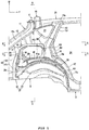
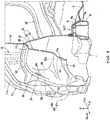
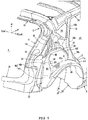
Fig. 1] Fig. 1 is a right side view of a main section of a rear body structure according to an embodiment. - [
Fig. 2] Fig. 2 is a vertical cross-sectional view of a main section of a right surface of the rear body structure according to this embodiment when seen from a cabin side. - [
Fig. 3] Fig. 3 is a perspective view of the main section of the rear body structure according to this embodiment that is seen obliquely downward from a front right side. - [
Fig. 4] Fig. 4 is a perspective view in which a cross section taken along line A-A inFig. 1 is seen obliquely rightward from above. - [
Fig. 5] Fig. 5 is a perspective view in which the main section of the rear body structure according to this embodiment is seen obliquely downward from a rear right side. - [
Fig. 6] Fig. 6 is a cross-sectional view of the main section taken along line B-B inFig. 1 . - [
Fig. 7] Fig. 7 is a cross-sectional view of the main section taken along line C-C inFig. 1 . - A detailed description will hereinafter be made on an embodiment of the present invention with reference to the drawings. In the drawings, an arrow F indicates a vehicle front direction, an arrow R indicates a vehicle right direction, an arrow L indicates a vehicle left direction, an arrow U indicates a vehicle up direction, an arrow out indicates a cabin outer side (an outer side in a vehicle width direction), and an arrow in indicates a cabin side (an inner side in the vehicle width direction).
- A vehicle rear body structure in this embodiment is substantially and bilaterally symmetrical. Thus, a description will be centered on a configuration on a right side of the vehicle. In the drawings, an outer panel as a body outer plate is not illustrated unless otherwise particularly noted. In addition, in the following description, a reinforcement will be abbreviated as a rein.
- As illustrated in
Fig. 1 andFig. 2 , the vehicle in this embodiment is an automobile of a door hatchback type, includes a rear gate opening 1 (seeFig. 5 ), which is opened rearward from a trunk or a boot as a rear section provided in a body rear portion, in the body rear portion. Therear gate opening 1 includes a rear gate of a flip-open type (not illustrated). - A description will be made on a lower portion of the body rear portion as a premised structure of the vehicle rear body structure in this embodiment.
- As illustrated in
Fig. 2 , in the lower portion of the body rear portion, arear seat pan 2, on which rear seats (not illustrated) are placed, and arear floor panel 3 for forming the trunk are provided. On both sides of theserear seat pan 2 and therear floor panel 3,rear side frames 4, each of which extends in a vehicle front-rear direction, are provided. In addition, on a boundary section between theserear seat pan 2 andrear floor panel 3, across member 5 that extends in the vehicle width direction is particularly provided. - The
rear side frame 4 particularly includes: a rear side frame upper 4a (seeFig. 2 andFig. 4 ) having a hat-shaped cross section that is opened downward and is projected upward; and a rear side frame lower 4b (seeFig. 4 ) having a hat-shaped cross section that is opened upward and is projected downward. These constitutes aclosed cross section 4s that extends in the vehicle front-rear direction therein. Inner edges in the vehicle width direction of the rear side frames 4 on both of the sides hold and fix outer edges in the vehicle width direction of therear seat pan 2 and therear floor panel 3 therebetween. - As illustrated in
Fig. 2 andFig. 6 , on a cabin side of awheel house 30, particularly a rear wheel house, therear side frame 4 extends in the vehicle front-rear direction from a rear end of therear floor panel 3 and passes thewheel house 30. A front end portion of therear side frame 4 is connected to a rear portion of a side sill 6 (not illustrated). - A
damper attachment section 7 to which an upper end portion of an unillustrated rear suspension damper (hereinafter abbreviated as a "damper") is attached for support is particularly provided at a position that is an intermediate position in the vehicle front-rear direction of the rear side frame 4 (a position corresponding to an unillustrated rear suspension) and that corresponds to the cabin side of thewheel house 30, which will be described later. - A reinforcing
member 8 that reinforces a portion around thedamper attachment section 7 is particularly provided in an upper portion of therear side frame 4. The reinforcingmember 8 is particularly shaped by aluminum die-casting or the like, and is provided to cover the portion around thedamper attachment section 7 from above while extending between the upper portion of therear side frame 4 and thewheel house 30. - The
damper attachment section 7 is particularly configured to include: adamper insertion hole 7a through which the damper is inserted; anddamper fastening sections 7b provided on both front and rear sides of thedamper insertion hole 7a to fasten and fix the damper to therear side frame 4 and the reinforcingmember 8. Each of thesedamper insertion hole 7a and thedamper fastening sections 7b on the front and rear sides has portions that respectively correspond to therear side frame 4 and the reinforcingmember 8 and thus perforated in a vertical direction. - The reinforcing
member 8 is particularly formed such that an upper surface thereof is one-step higher than an upper surface of therear side frame 4. On the upper surface of therear side frame 4, a circumferential edge of thedamper fastening section 7b on each of the front and rear sides is recessed downward. - Next, a description will be made on a side portion of the vehicle rear body in this embodiment.
- As illustrated in
Fig. 1 to Fig. 3 , in the side portion of the rear body in this embodiment is particularly provided with arear pillar 11, a sideinner panel 12, anintermediate pillar 13, first and second inner-side reins 14, 15 (seeFig. 2 ), thewheel house 30, and first and second door opening rearedge reinforcing members 16, 17 (a first door opening rearedge reinforcing member 16 and a second door opening rear edge reinforcing member 17). - The
rear pillar 11 extends downward and rearward from a side on each of right and left sides of therear gate opening 1, and aclosed cross section 11s (seeFig. 6 ) that extends along an extending direction of therear pillar 11 is defined therein. - Just as described, the
rear pillar 11, which extends in the vehicle front-rear direction (the vertical direction) in the body rear portion, has an upper end that is joined to an outer end in the vehicle width direction of arear header 18 extending in the vehicle width direction along an upper side of therear gate opening 1 and to a rear end of aroof side rail 21 extending along the vehicle front-rear direction on each side of a roof section. Such a joined portion will hereinafter be referred to as a "joined section C". A lower end portion of therear pillar 11 is particularly joined to an outer end in the vehicle width direction of arear end member 22 that extends in the vehicle width direction along a lower edge of the rear gate opening 1 (seeFig. 2 andFig. 4 ). - The side
inner panel 12 is particularly a panel that forms a trunk side wall. A lower portion of the sideinner panel 12 is disposed up to a circumferential edge (mainly an upper portion and a front portion) of thewheel house 30 on the side of the body rear portion except for a lower portion of the circumferential edge in a manner to be held between a wheel house inner 31 and a wheel house outer 32, which will be described later. - In particular, a portion of the side
inner panel 12 above thewheel house 30 is disposed between therear pillar 11 and thewheel house 30. - As illustrated in
Fig. 1 andFig. 3 , theintermediate pillar 13 particularly corresponds to a front side of anopening 23 for a quarter window. Anupper end 13a of theintermediate pillar 13 is joined to a rear portion of theroof side rail 21 by spot welding or the like. - The
opening 23 for the quarter window is particularly constructed of the rear portions of theintermediate pillar 13 and theroof side rail 21 and an upper portion of a front edge of the sideinner panel 12. - As illustrated in
Fig. 2 andFig. 6 , on the cabin side in the side portion of the vehicle rear portion, the first and second inner-side reins 14, 15 (the first inner side rein 14 and the second inner side rein 15) are provided on each side in the vehicle front-rear direction. Each of the first and second inner-side reins rear side frame 4 to at least a portion of the sideinner panel 12 above the wheel house inner 31 in a manner to run across the wheel house inner 31 in the vertical direction (seeFig. 2 ). - Each of these first and second inner-
side reins inner panel 12 to define respective one ofclosed cross sections Fig. 6 andFig. 7 ). - As illustrated in
Fig. 2 , the first inner side rein 14 on the front side extends upward to a substantially lower end portion of theintermediate pillar 13 from an outer end in the vehicle width direction of anupper cross member 5A, which is projected upward (has a hat-shaped cross section opened downward) with respect to therear floor panel 3, in thecross member 5, so as to run across the wheel house inner 31. - The second inner side rein 15 on the rear side extends upward across the wheel house inner 31 and the side
inner panel 12 from therear side frame 4, and an upper end of the second inner side rein 15 is joined to an upper portion of the rear pillar 11 (seeFig. 2 ). - More specifically, the upper end of the second inner side rein 15 is particularly joined to a portion of the
rear pillar 11, which extends while tilting downward to the rear, and the portion is slightly separated rearward from the joined section C (the front end) with therear header 18. - A lower portion of each of the first and second inner-
side reins member 8. The first and second inner-side reins rear side frame 4 on front and rear sides of the damper attachment section 7 (the front and rear sides of thedamper insertion hole 7a) via the reinforcingmember 8. In particular, a position of the lower portion of the second inner side rein 15 matches a position of thedamper fastening section 7b on the rear side in the vehicle front-rear direction of therear side frame 4, and the second inner side rein 15 extends upward in a substantially linear manner from a portion corresponding to thedamper fastening section 7b on the rear side (seeFig. 2 ). - As illustrated in
Fig. 4 , thewheel house 30 is configured that an upper portion of a rear wheel (not illustrated) can be accommodated from a rear side to a front side thereof in the wheel house inner 31, which is bulged to the cabin side (or toward the cabin), and the wheel house outer 32, which is bulged to the cabin outer side (or outward from the cabin). - Each of the wheel house inner 31 and the wheel house outer 32 is particularly configured to include: a bulged
section 33 that is bulged to respective one of the cabin side and the cabin outer side; and aflange 34 that is formed at an outer edge thereof except for a lower edge when seen in the vehicle side view. Theflanges 34 are joined to each other so as to hold a lower edge of the sideinner panel 12 therebetween. - A detailed description will hereinafter be made on the wheel house outer 32.
- Particularly, the bulged
section 33 of the wheel house outer 32 is integrally formed with a wheel arch-shapedsection 35 and an upward extending section 36 (a shelf section). The wheel arch-shapedsection 35 is provided in a lower portion including a lower edge of the bulgedsection 33, and, in an upper portion of the bulgedsection 33, the upward extendingsection 36 extends upward from the wheel arch-shapedsection 35. - The wheel house inner 31 is particularly formed to correspond or adapted to the wheel house outer 32 and thus extends upward to the substantially same height as the bulged section 33 (see
Fig. 4 ). - The wheel arch-shaped
section 35 is formed in a shape that follows a lower edge of the wheel house outer 32, that is, an arch shape (an arcuate shape) in which an intermediate portion in the vehicle front-rear direction is projected upward when seen in the vehicle side view. - As illustrated in
Fig. 1 andFig. 5 , a front portion of the wheel arch-shapedsection 35 is particularly formed to be gradually lowered to the front, and a front lower end thereof is connected to a rear portion of theside sill 6. The front portion of the wheel arch-shapedsection 35 is particularly formed such that a front edge thereof is located in front of the front edge of the sideinner panel 12, so as to form a lower portion of arear edge 24r of adoor opening 24, which is provided on the body side portion and is used for seating on and leaving from the rear seat (seeFig. 1 ). - As illustrated in
Fig. 1 , the upward extendingsection 36 particularly extends upward from the wheel arch-shapedsection 35, and a lower end portion thereof extends upward from a rear end of the wheel arch-shapedsection 35 such that the upward extendingsection 36 has a width in the vehicle front-rear direction between the rear end and a position slightly in front of an apex (an upper end) of the wheel arch-shapedsection 35. That is, the upward extendingsection 36 is provided across the second inner side rein 15 in the vehicle front-rear direction. - The bulged
section 33 is integrally formed such that internal spaces of the upward extendingsection 36 and the wheel arch-shapedsection 35 provided on upper and lower sides thereof communicate with each other in the vertical direction (seeFig. 4 ) . - Meanwhile, as illustrated in
Fig. 3 to Fig. 6 , the upward extendingsection 36 is formed such that a bulged length (a bulged amount) to the cabin outer side of the substantially entire upward extendingsection 36 except for arear portion 36r is less than that of the wheel arch-shapedsection 35. In this example, the substantially entire upward extendingsection 36 except for therear portion 36r is bulged to have the bulged length that is approximately one half of the bulged length of the wheel arch-shapedsection 35. Meanwhile, arear portion 35r of the wheel arch-shapedsection 35 is bulged such that, as therear portion 35r is gradually lowered, a bulged length thereof becomes substantially equal to the bulged length of the wheel arch-shaped section 35 (seeFigs. 3 to 6 ). - Such a bulged
section 33, that is, the wheel arch-shapedsection 35 and the upward extendingsection 36 are each formed in a bulged shape to the cabin outer side. In this way, step-shapedridgeline sections - That is, the
ridgeline sections - More specifically, when seen in the vehicle side view, in the wheel arch-shaped
portion 35, aridgeline section 41 in an arch shape (hereinafter also referred to as an "arch-shapedridgeline section 41") is formed along a circumferential edge (an upper edge portion from the rear end to a front end) except for a lower end. - The arch-shaped
ridgeline section 41 particularly includes: afront side portion 41f that extends to be located downward to the front; anupper side portion 41u that extends substantially horizontally across the apex of the wheel arch-shapedsection 35 in the vehicle front-rear direction; and arear side portion 41r that extends in the vertical direction more steeply than the front side portion while being inclined downward to the rear. Of these, while thefront side portion 41f and theupper side portion 41u extend continuously when seen in the vehicle side view, theupper side portion 41u and therear side portion 41r are separated from each other via therear portion 35r of the wheel arch-shapedsection 35. - Here, as described above, the
rear portion 35r of the wheel arch-shapedsection 35 and therear portion 36r of the upward extendingsection 36 positioned right above therear portion 35r are formed to have the substantially same bulged amount to the cabin outer side. In addition, as described above, a boundary between therear portions section 35 and the upward extendingsection 36 in the vertical direction is located between theupper side portion 41u and therear side portion 41r of the arch-shapedridgeline section 41. Accordingly, theupper side portion 41u and therear side portion 41r of the arch-shapedridgeline section 41 are formed discontinuously in the vehicle front-rear direction. - As illustrated in
Fig. 1 ,Fig. 3 , andFig. 5 , when seen in the vehicle side view, in the upward extendingsection 36, a ridgeline section 42 (hereinafter also referred to as an "upward extendingridgeline section 42") is provided along a circumferential edge except for a lower end. - The upward extending
ridgeline section 42 particularly includes: afront side portion 42f that extends to be located downward to the front; anupper side portion 42u that extends substantially horizontally in the vehicle front-rear direction; and arear side portion 42r that extends in the vertical direction more steeply than thefront side portion 42f while being inclined downward to the rear. Thesefront side portion 42f, theupper side portion 42u, and therear side portion 42r extend continuously along the circumferential edge except for the lower end of the upward extendingsection 36 when seen in the vehicle side view. - The
front side portion 42f of the upward extendingridgeline section 42 extends in the vertical direction more gently than therear side portion 42r, and thisfront side portion 42f is set as a first verticaldirection ridgeline section 42f. - This first vertical
direction ridgeline section 42f is formed by thefront side portion 42f of the upward extendingridgeline section 42, extends downward to the front so as to reach the wheel arch-shapedsection 35, and extends in the vertical direction at a separated position on a front side from the second inner side rein 15. - The
rear side portion 42r of the upward extendingridgeline section 42 and therear side portion 41r of the wheel arch-shapedsection 35 extend continuously along the vertical direction when seen in the vehicle side view, and are collectively set as a second verticaldirection ridgeline section 43. - A rear edge of the bulged
section 33 extends continuously over an substantially entire length of the wheel house outer 32 in the vertical direction, and the second verticaldirection ridgeline section 43 is formed in a vertical wall shape that is inclined steeply, so as to be located forward to the above by the rear edge of this bulgedsection 33. - At a separated position on the vehicle rear side from the second inner side rein 15, the second vertical
direction ridgeline section 43 extends substantially linearly to the above (the rear pillar 11) from the height of therear side frame 4. - Here, as described above, the
rear portion 36r of the upward extendingsection 36 is formed to be gradually bulged to the cabin outer side as therear portion 36r is lowered so that the bulged amount of the lower portion thereof is substantially the same as that of therear portion 35r of the wheel arch-shapedsection 35 to the cabin outer side. - In addition, as illustrated in
Fig. 3 ,Fig. 5 , andFig. 6 , therear portion 36r of the upward extendingsection 36 is formed to be bulged to the cabin outer side when compared to the front portion. Thus, a front edge (44) of therear portion 36r is formed in a vertical wall shape that extends in the vertical direction. Accordingly, therear portion 36r of the upward extendingsection 36 is also formed with aridgeline section 44 by the front edge (44) in the vertical wall shape of therear portion 36r. For this reason, theridgeline section 44 at the front edge of therear portion 36r of the upward extendingsection 36 is set as a third verticaldirection ridgeline section 44. - Similarly to the second vertical
direction ridgeline section 43, at a separated position on the vehicle rear side from the second inner side rein 15, this third verticaldirection ridgeline section 44 extends in the vertical direction. - In addition, both of the
upper side portion 42u of the upward extendingridgeline section 42 and theupper side portion 41u of the arch-shapedridgeline section 41 extend across the second inner side rein 15 in the vehicle front-rear direction, and overlap the second inner side rein 15 when seen in the vehicle side view. - As illustrated in
Fig. 1 ,Fig. 3 ,Fig. 5 , andFig. 6 , the first and second door opening rearedge reinforcing members rear edge 24r, are particularly provided at therear edge 24r of thedoor opening 24, which is used for seating on and leaving from the rear seat. - The first door opening rear
edge reinforcing member 16 is a reinforcing member that reinforces an intermediate portion in the vertical direction of therear edge 24r of the door opening 24 (between theintermediate pillar 13 and the wheel arch-shaped section 35). The first door opening rearedge reinforcing member 16 is formed to have a hat-shaped cross section such that a cross section orthogonal to the extending direction thereof is opened to the cabin side, and cooperates with the sideinner panel 12 to define aclosed cross section 16s with the side inner panel 12 (seeFig. 6 andFig. 7 ). An upper end of the first door opening rearedge reinforcing member 16 is joined to a lower end of theintermediate pillar 13, and a lower end of the first door opening rearedge reinforcing member 16 is joined to a front lower portion of the upward extendingsection 36, that is, a lower portion of the first verticaldirection ridgeline section 42f (see the first door opening rearedge reinforcing member 16 indicated by imaginary lines inFig. 3 ). - The second door opening rear
edge reinforcing member 17 is a reinforcing member that reinforces a lower portion of therear edge 24r of the door opening 24 (thefront side portion 41f of the wheel arch-shaped section 35), extends along the lower portion of therear edge 24r of thedoor opening 24, that is, thefront side portion 41f of the wheel arch-shapedsection 35, and is formed to have a hat-shaped cross section such that a cross section orthogonal to the extending direction is opened to thefront side portion 41f. Then, the second door opening rearedge reinforcing member 17 cooperates with thefront side portion 41f of the wheel arch-shapedsection 35 so as to define aclosed cross section 17s with the wheel arch-shaped section 35 (seeFig. 1 andFig. 2 ). - A rear upper portion of the second door opening rear
edge reinforcing member 17 is joined to a lower portion (a root portion) of the first door opening rearedge reinforcing member 16, and a front lower portion of the second door opening rearedge reinforcing member 17 is joined to the rear portion of the side sill 6 (seeFig. 1 ). - The vehicle rear body structure according to above-described embodiment is the vehicle rear body structure that is provided with the
wheel house 30 having: the wheel house outer 32 in the bulged shape to the cabin outer side; and the wheel house inner 31 located on the cabin side from the wheel house outer 32. While the wheel house inner 31 is provided with the second inner side rein 15 (the inner-side reinforcement) that extends in the vertical direction, the bulgedsection 33 formed in the wheel house outer 32 in the manner to be bulged to the cabin outer side includes the wheel arch-shapedsection 35 formed in the arch shape to cover the rear wheel from above when seen in the vehicle side view. The wheel house outer 32 is formed with the upward extending ridgeline section 42 (the ridgeline section 42) that extends upward to the position above the wheel arch-shapedsection 35 along the bulged shape of the bulgedsection 33 bulged to the cabin outer side, and at least the portion of the upward extending ridgeline section 42 (the ridgeline section 42) overlaps the second inner side rein 15 when seen in the vehicle side view (seeFig. 1 andFig. 3 toFig. 7 ) . - According to the above configuration, the portion of the wheel house outer 32, which overlaps the second inner side rein 15 when seen in the vehicle side view, is reinforced by the
ridgeline sections section 33. Thus, it is possible to improve rigidity without adding a reinforcing component. - More specifically, according to the above configuration, in the wheel house outer 32, the
ridgeline section 42 that extends upward to the position above the wheel arch-shapedsection 35 is formed by the bulged shape of the bulgedsection 33. Thus, it is possible to reinforce the wheel house outer 32 itself, that is, the cabin outer side in the body rear portion without adding a component such as a reinforcing member (that is, increasing body weight). - In addition, the
ridgeline section 42 is formed to overlap the second inner side rein 15 when seen in the vehicle side view. That is, in this example, of the upward extendingridgeline section 42, theupper side portion 42u extends in the vehicle front-rear direction across the second inner side rein 15, which extends in the vertical direction. Thus, the upward extendingridgeline section 42 and the second inner side rein 15 cooperate with each other to increase the rigidity around thewheel house 30 from both sides that are the cabin side (the inner side) and the cabin outer side (the outer side). - As an aspect of the present invention, according to the above configuration, at the position above the wheel arch-shaped
section 35 in the bulgedsection 33, the upward extendingsection 36 is provided to be bulged to the cabin outer side so as to extend upward from the wheel arch-shapedsection 35. The upward extendingridgeline section 42 is formed along the bulged shape of the upward extendingsection 36 to the cabin outer side (seeFig. 1 andFig. 3 toFig. 7 ). - According to the above configuration, the bulged
section 33 allows the integral formation of the upward extendingsection 36 and the wheel arch-shapedsection 35 on the upper and lower sides. Thus, it is possible to increase strength of the wheel house outer 32. - As an aspect of the present invention, the
rear side frame 4, which is provided on the cabin side and in the lower portion of thewheel house 30, is provided with thedamper attachment section 7 to which the upper end portion of the damper (not illustrated) is attached for support (seeFig. 2 andFig. 6 ). The second inner side rein 15 extends upward from the damper attachment section 7 (the rear sidedamper fastening section 7b in this example), which is provided in therear side frame 4, in the vehicle front-rear direction (seeFig. 2 ). Theridgeline sections direction ridgeline section 43 continuously extends upward across the wheel arch-shapedsection 35 from the height of therear side frame 4 to the upward extending section 36 (seeFig. 1 andFig. 3 toFig. 5 ). - According to the above configuration, similar to the second inner side rein 15, the second vertical
direction ridgeline section 43 extends upward from the height of therear side frame 4. Thus, the second verticaldirection ridgeline section 43 can suppress the displacement of the second inner side rein 15, which is caused by an external force applied from the damper to the body side via thedamper attachment section 7. - In detail, in order to disperse the external force, which is applied from the damper to the body side via the
damper attachment section 7, for example, only the cabin side is reinforced by providing the second inner side rein 15, which extends upward from thedamper attachment section 7 in the cabin side, or the like. In such a case, a difference in rigidity occurs between the cabin side and the cabin outer side. Thus, it is necessary to relatively increase the strength on the cabin outer side. - However, in the case where the cabin outer side (the wheel house outer 32) is simply reinforced by providing the reinforcing member, or the like, the body weight (the number of components) is increased.
- Meanwhile, in this embodiment, the
ridgeline sections 41, 42 (particularly, the second vertical direction ridgeline section 43), each of which extends upward from the height of therear side frame 4, are formed in the wheel house outer 32 by the bulged shape of the bulgedsection 33. In this way, it is possible to also reinforce the cabin outer side, and thus can cancel the difference in rigidity between the cabin side and the cabin outer side. - As a result, the number of the components (the body weight) of the vehicle is not increased, and the external force, which is transmitted from the damper to the body rear portion, can effectively be dispersed above the body by the second inner side rein 15 and the
ridgeline sections - As an aspect of the present invention, the first door opening rear edge reinforcing member 16 (the door opening rear edge reinforcing member) is joined to the upward extending
section 36, the first door opening rear edge reinforcing member 16 (the door opening rear edge reinforcing member) extending along therear edge 24r of the door opening 24 provided in the body side portion and used for seating on and leaving from the rear seat (seeFig. 1 ,Fig. 3 , andFig. 5 toFig. 7 ). Thefront side portion 42f and theupper side portion 42u of the upward extendingridgeline section 42 continuously extend to the first door opening rearedge reinforcing member 16 and the second inner side rein 15, which is provided on the vehicle rear side of the first door opening rear edge reinforcing member 16 (seeFig. 1 ,Fig. 3 ,Fig. 5 , andFig. 6 ). - According to the above configuration, in the rear body structure, it is possible to increase the rigidity of the portion from the
rear edge 24r of the door opening 24 to the second inner side rein 15. - That is, the first door opening rear
edge reinforcing member 16 and the second inner side rein 15 are connected by thefront side portion 42f and theupper side portion 42u of the upward extendingridgeline section 42 when seen in the vehicle side view. In this way, compared to a case where thesecomponents edge reinforcing member 16 and second inner side rein 15. - As an aspect of the present invention, the
rear header 18, which extends in the vehicle width direction, is provided on the vehicle front side and the vehicle upper side of the second inner side rein 15. The rear pillar 11 (the closed cross-sectional structure), which extends rearward from therear header 18 and is lowered to the rear, is provided above thewheel house 30. The upper end of the second inner side rein 15 is joined to the portion, which is separated rearward from the joined section C with therear header 18, in the rear pillar 11 (see particularlyFig. 2 ofFig. 1 to Fig. 5 ). - In detail, in the configuration in which the
rear pillar 11, which constitutes the lateral side of therear gate opening 1, is provided to be lowered rearward from the outer end in the vehicle width direction of therear header 18, it is concerned that therear pillar 11 vibrates (swings) and is deformed with therear header 18 as a point of origin during travel of the vehicle when seen in the vehicle side view and when seen in the vehicle rear view. - More specifically, during the travel of the vehicle, the lower rear portion of the
rear pillar 11 vibrates in the vertical direction (in the front-rear direction) with therear header 18 being a fulcrum point when seen in the vehicle side view. When seen in the vehicle rear view, the lower rear portion thereof vibrates between the inner side and the outer side with therear header 18 being the fulcrum point. - Meanwhile, in this embodiment, the portion of the
rear pillar 11 separated from the joined section C with therear header 18 is supported by the upper end of the second inner side rein 15. In this way, compared to the case where the joined section C of therear pillar 11 with therear header 18 is supported, it is possible to effectively suppress the above-described deformation of therear pillar 11 during the travel (with the principle of leverage). - As an aspect of the present invention, at the separated position on the vehicle rear side from the second inner side rein 15, the second vertical
direction ridgeline section 43 as the ridgeline section extends in the vertical direction (seeFig. 1 andFig. 3 toFig. 7 ). - According to the above configuration, the second vertical
direction ridgeline section 43 extends upward at the separated position from the second inner side rein 15 in the vehicle front-rear direction. Thus, from the portion that is further separated rearward in the vehicle from the joined section C of the second inner side rein 15 with therear header 18, the second verticaldirection ridgeline section 43 can further effectively suppress the deformation of therear pillar 11 with therear header 18 being the point of origin during the travel of the vehicle when seen in the vehicle side view and when seen in the vehicle rear view. - In detail, as described above, instead of directly supporting the joined section C of the
rear pillar 11 to therear header 18 by the upper end of the second inner side rein 15 extending in the vertical direction, the portion, which is further separated rearward in the vehicle from the joined section C to therear header 18, in therear pillar 11 is supported by the upper end of the second inner side rein 15. This is effective to suppress the above-described deformation of therear pillar 11 with the principle of leverage. - However, in order to transmit and disperse the external force, which is applied to the body side from the damper via the
damper attachment section 7, as illustrated inFig. 2 , the second inner side rein 15 is preferably provided to extend upward (in a vertically upper direction when possible) from thedamper attachment section 7. - The position in the vehicle front-rear direction of such a second inner side rein 15 possibly restricts provision of the second inner side rein 15 at the position separated as much as possible to the rear in the vehicle from the joined section C with the
rear header 18 in therear pillar 11. - Thus, in this embodiment, the bulged
section 33 of the wheel house outer 32 is provided with the upward extendingsection 36, which is closer to therear pillar 11 than the wheel arch-shapedsection 35. In this way, it is configured that the upward extendingsection 36 also has an effect of suppressing the vibrations of therear pillar 11. - That is, the wheel house outer 32 is formed with the second vertical
direction ridgeline section 43, which extends upward above the wheel arch-shapedsection 35. In this way, it is possible to simultaneously exert an effect of transmitting and dispersing an input load from the damper to the body side and a vibration suppression effect for therear pillar 11 without the increase in the body weight. - As an aspect of the present invention, the upward extending
section 36 is provided with the plurality of the upward extending ridgeline sections 42 (the ridgeline sections), each of which extends in the vertical direction (seeFig. 1 andFig. 3 to 7 ). That is, in this example, as the upward extendingridgeline sections 42 extending in the vertical direction, the first verticaldirection ridgeline section 42f, the second verticaldirection ridgeline section 43, and the third verticaldirection ridgeline section 44 are provided (seeFig. 1 andFig. 3 to 7 ). - In particular, the second and third vertical
direction ridgeline sections direction ridgeline sections rear pillar 11 with therear header 18 being the point of origin. - Here, the portions of the
ridgeline sections 42 that extend upward are not limited to the second verticaldirection ridgeline section 43 and the third verticaldirection ridgeline section 44 as described above. However, three or more of theridgeline sections 42 may be provided. - The present invention is not limited to the configuration in the above-described embodiment, but can be implemented in various embodiments.
- In this embodiment, the upward extending
ridgeline section 42 includes the ridgeline portion in which thefront side portion 42f, theupper side portion 42u, and therear side portion 42r continuously extend along the outer edge of the upward extendingsection 36. However, the present invention is not limited thereto. Thefront side portion 42f, theupper side portion 42u, and therear side portion 42r may separately be formed in a discontinued manner as long as at least a portion of the upward extendingridgeline section 42 overlaps the second inner side rein 15 when seen in the vehicle side view. - In addition, the upward extending
ridgeline section 42 is not limited that the portion extending in the vehicle front-rear direction overlaps so as to intersect the second inner side rein 15 when seen in the vehicle side view as in this embodiment. However, it may be configured that the portion extending in the vertical direction overlaps the second inner side rein 15 when seen in the vehicle side view. -
- 4: Rear side frame
- 7: Damper attachment section
- 11: Rear pillar (closed cross-sectional structure)
- 15: Second inner side rein (inner-side reinforcement)
- 16: First door opening rear edge reinforcing member (door opening rear edge reinforcing member)
- 18: Rear header
- 24: Door opening used for seating on and leaving from rear seat
- 24r: Rear edge of door opening used for seating on and leaving from rear seat
- 30: Wheel house
- 31: Wheel house inner
- 32: Wheel house outer
- 33: Bulged section
- 35: Wheel arch-shaped section
- 36: Upward extending section
- 42: Vertical direction ridgeline section (ridgeline section)
- 42f, 42u: Front side portion and upper side portion of upward extending ridgeline section (ridgeline extending to door opening rear edge reinforcing member and inner-side reinforcement)
- 43: Second vertical direction ridgeline section (ridgeline section extending in vertical direction at position separated to rear in vehicle from inner-side reinforcement)
- 43, 44: Second vertical direction ridgeline section and third vertical direction ridgeline section (plurality of ridgeline sections extending in vertical direction)
- C: Joined section of rear pillar to rear header
Claims (15)
- A vehicle rear body structure provided with a wheel house (30) that includes a wheel house outer (32) in a bulged shape to a cabin outer side, and a wheel house inner (31) located on a cabin side from the wheel house outer (32), wherein
the wheel house inner (31) is provided with an inner-side reinforcement (15) that extends in a vertical direction,
in the wheel house outer (32), a bulged section (33) that is formed to be bulged to the cabin outer side includes a wheel arch-shaped section (35) that is formed in an arch shape configured to cover a rear wheel from above when seen in a vehicle side view, and
the wheel house outer (32) is formed with a ridgeline section (42) that extends upward above the wheel arch-shaped section (35) along a bulged shape of the bulged section (33) to the cabin outer side and at least a portion of which overlaps the inner-side reinforcement (15) when seen in the vehicle side view. - The vehicle rear body structure according to claim 1, wherein
in a portion above the wheel arch-shaped section (35) in the bulged section (33), an upward extending section (36) that is bulged to the cabin outer side is provided to extend upward from the wheel arch-shaped section (35). - The vehicle rear body structure according to claim 2, wherein
the ridgeline section (42) is formed along a bulged shape of the upward extending section (36) to the cabin outer side. - The vehicle rear body structure according to claim 2 or 3, wherein
a damper attachment section (7) to which an upper end portion of a suspension damper is to be attached for support is provided in a rear side frame (4) provided on the cabin side and in a lower portion of the wheel house (30). - The vehicle rear body structure according to claim 4, wherein
the inner-side reinforcement (15) extends upward from the damper attachment section (7) provided in the rear side frame (4) . - The vehicle rear body structure according to claim 4 or 5, wherein
the ridgeline section (42) of the wheel house outer (32) extends upward across the wheel arch-shaped section (35). - The vehicle rear body structure according to claim 6, wherein
the ridgeline section (42) of the wheel house outer (32) extends upward across the wheel arch-shaped section (35) from a height of the rear side frame (4) to the upward extending section (36) . - The vehicle rear body structure according to any one of claims 2 to 7, wherein
a door opening rear edge reinforcing member (16) is joined to the upward extending section (36), the door opening rear edge reinforcing member (16) extending along a rear edge of a door opening (24) provided in a body side portion and used for seating on and/or leaving from a rear seat. - The vehicle rear body structure according to claim 8, wherein
the ridgeline section (42) extends to the door opening rear edge reinforcing member (16) and the inner-side reinforcement (15), which is provided on a vehicle rear side from the door opening rear edge reinforcing member (16). - The vehicle rear body structure according to any one of claims 2 to 9, wherein
a rear header (18) that extends in a vehicle width direction is provided on a vehicle front side and a vehicle upper side from the inner-side reinforcement (15). - The vehicle rear body structure according to claim 10, wherein
a closed cross-sectional structure (11) that extends rearward from the rear header (18) and is lowered to the rear is provided above the wheel house (30). - The vehicle rear body structure according to claim 11, wherein
an upper end of the inner-side reinforcement (15) is joined to a portion, which is separated rearward from a joined section (C) with the rear header, in the closed cross-sectional structure (11) . - The vehicle rear body structure according to any one of claims 2 to 12, wherein
the ridgeline section (43) extends in the vertical direction at a position that is separated rearward in the vehicle from the inner-side reinforcement (15). - The vehicle rear body structure according to claim 13, wherein
the upward extending section (36) is provided with one or a plurality of the ridgeline sections (42f, 43, 44), each of which extends in the vertical direction. - An vehicle comprising the vehicle rear body structure according to any one of the preceding claims.
Applications Claiming Priority (1)
| Application Number | Priority Date | Filing Date | Title |
|---|---|---|---|
| JP2019078317A JP7259506B2 (en) | 2019-04-17 | 2019-04-17 | vehicle rear body structure |
Publications (2)
| Publication Number | Publication Date |
|---|---|
| EP3725646A1 true EP3725646A1 (en) | 2020-10-21 |
| EP3725646B1 EP3725646B1 (en) | 2022-09-07 |
Family
ID=69784181
Family Applications (1)
| Application Number | Title | Priority Date | Filing Date |
|---|---|---|---|
| EP20161821.2A Active EP3725646B1 (en) | 2019-04-17 | 2020-03-09 | Vehicle rear body structure, and vehicle |
Country Status (4)
| Country | Link |
|---|---|
| US (1) | US11273874B2 (en) |
| EP (1) | EP3725646B1 (en) |
| JP (1) | JP7259506B2 (en) |
| CN (1) | CN111824268B (en) |
Cited By (1)
| Publication number | Priority date | Publication date | Assignee | Title |
|---|---|---|---|---|
| FR3116257A1 (en) * | 2020-11-18 | 2022-05-20 | Psa Automobiles Sa | REAR WHEELHOUSE BOX WITH ENHANCED PROTECTION |
Families Citing this family (7)
| Publication number | Priority date | Publication date | Assignee | Title |
|---|---|---|---|---|
| JP7284132B2 (en) * | 2020-09-04 | 2023-05-30 | トヨタ自動車株式会社 | vehicle body |
| KR20220055292A (en) * | 2020-10-26 | 2022-05-03 | 현대자동차주식회사 | Rear side structure for vehicle |
| KR20220096102A (en) * | 2020-12-30 | 2022-07-07 | 현대자동차주식회사 | Rear floor side member assenbly |
| CN113147904B (en) * | 2021-05-18 | 2022-11-11 | 上汽通用五菱汽车股份有限公司 | Two electric motor car door ring strengthening frame subassemblies |
| CN115214785B (en) * | 2021-12-09 | 2023-09-01 | 广州汽车集团股份有限公司 | Automobile body rear structure and car |
| CN114735083B (en) * | 2022-05-05 | 2023-09-19 | 北京汽车股份有限公司 | Car body C post assembly and car |
| CN117360627A (en) * | 2022-06-29 | 2024-01-09 | 长城汽车股份有限公司 | Vehicle body components and vehicles |
Citations (5)
| Publication number | Priority date | Publication date | Assignee | Title |
|---|---|---|---|---|
| US20070138837A1 (en) * | 2005-12-15 | 2007-06-21 | Mazda Motor Corporation | Vehicle body structure |
| JP2012006507A (en) | 2010-06-25 | 2012-01-12 | Mazda Motor Corp | Rear body structure of vehicle |
| DE102015009155A1 (en) * | 2014-07-22 | 2016-01-28 | Mazda Motor Corporation | A rear vehicle body structure of a vehicle and method for reinforcing a rear vehicle body structure |
| JP2016132334A (en) * | 2015-01-19 | 2016-07-25 | マツダ株式会社 | Rear body structure of automobile |
| DE102016104045A1 (en) * | 2015-04-17 | 2016-10-20 | Suzuki Motor Corporation | Vehicle rear structure |
Family Cites Families (12)
| Publication number | Priority date | Publication date | Assignee | Title |
|---|---|---|---|---|
| JP2543414Y2 (en) * | 1992-04-20 | 1997-08-06 | トヨタ車体株式会社 | Rear wheel house structure of a leaf spring axle suspension type car |
| JP2001063630A (en) | 1999-08-26 | 2001-03-13 | Nissan Motor Co Ltd | Body side structure |
| JP2009067231A (en) | 2007-09-13 | 2009-04-02 | Mazda Motor Corp | Vehicle rear body structure |
| JP5589879B2 (en) | 2011-02-10 | 2014-09-17 | トヨタ自動車株式会社 | Body structure |
| JP5798605B2 (en) * | 2013-10-04 | 2015-10-21 | 本田技研工業株式会社 | Vehicle rear structure |
| JP6137693B2 (en) | 2014-02-04 | 2017-05-31 | 本田技研工業株式会社 | Auto body structure |
| WO2016199499A1 (en) * | 2015-06-08 | 2016-12-15 | 本田技研工業株式会社 | Structure for rear part of vehicle body |
| DE102015008728A1 (en) * | 2015-07-07 | 2017-01-12 | GM Global Technology Operations LLC (n. d. Ges. d. Staates Delaware) | Motor vehicle body with multi-shell wheel installation |
| JP6409724B2 (en) | 2015-09-18 | 2018-10-24 | マツダ株式会社 | Car side body structure |
| US10093149B2 (en) * | 2017-01-18 | 2018-10-09 | Ford Global Technologies, Llc | Vehicle body with HVAC unit |
| JP6597760B2 (en) * | 2017-03-27 | 2019-10-30 | マツダ株式会社 | Rear body structure of the vehicle |
| JP6597761B2 (en) | 2017-03-27 | 2019-10-30 | マツダ株式会社 | Rear body structure of the vehicle |
-
2019
- 2019-04-17 JP JP2019078317A patent/JP7259506B2/en active Active
-
2020
- 2020-02-26 CN CN202010120774.3A patent/CN111824268B/en active Active
- 2020-03-09 EP EP20161821.2A patent/EP3725646B1/en active Active
- 2020-03-10 US US16/814,067 patent/US11273874B2/en active Active
Patent Citations (5)
| Publication number | Priority date | Publication date | Assignee | Title |
|---|---|---|---|---|
| US20070138837A1 (en) * | 2005-12-15 | 2007-06-21 | Mazda Motor Corporation | Vehicle body structure |
| JP2012006507A (en) | 2010-06-25 | 2012-01-12 | Mazda Motor Corp | Rear body structure of vehicle |
| DE102015009155A1 (en) * | 2014-07-22 | 2016-01-28 | Mazda Motor Corporation | A rear vehicle body structure of a vehicle and method for reinforcing a rear vehicle body structure |
| JP2016132334A (en) * | 2015-01-19 | 2016-07-25 | マツダ株式会社 | Rear body structure of automobile |
| DE102016104045A1 (en) * | 2015-04-17 | 2016-10-20 | Suzuki Motor Corporation | Vehicle rear structure |
Cited By (1)
| Publication number | Priority date | Publication date | Assignee | Title |
|---|---|---|---|---|
| FR3116257A1 (en) * | 2020-11-18 | 2022-05-20 | Psa Automobiles Sa | REAR WHEELHOUSE BOX WITH ENHANCED PROTECTION |
Also Published As
| Publication number | Publication date |
|---|---|
| JP2020175736A (en) | 2020-10-29 |
| US20200331538A1 (en) | 2020-10-22 |
| CN111824268B (en) | 2022-09-09 |
| US11273874B2 (en) | 2022-03-15 |
| JP7259506B2 (en) | 2023-04-18 |
| EP3725646B1 (en) | 2022-09-07 |
| CN111824268A (en) | 2020-10-27 |
Similar Documents
| Publication | Publication Date | Title |
|---|---|---|
| EP3725646B1 (en) | Vehicle rear body structure, and vehicle | |
| US9381944B2 (en) | Upper vehicle-body structure of automotive vehicle provided with sun roof | |
| US9604674B2 (en) | Rear vehicle-body structure of vehicle | |
| CN107848577B (en) | car body rear structure | |
| US11192593B2 (en) | Vehicle body structure of vehicle | |
| CN105813928B (en) | The sidepiece body structure of vehicle | |
| US9302711B2 (en) | Vehicle body rear structure | |
| US9616936B2 (en) | Upper vehicle-body structure of vehicle | |
| US11008048B2 (en) | Lower vehicle-body structure | |
| JP2020026231A (en) | Lower body structure | |
| EP3581470A1 (en) | Lower vehicle-body structure and method of producing a lower vehicle-body structure | |
| CN112046615B (en) | Upper vehicle body structure | |
| US9248863B2 (en) | Vehicle body superstructure | |
| EP3581472A1 (en) | Lower vehicle-body structure and method of producing a lower vehicle-body structure | |
| EP3718864B1 (en) | Vehicle side body structure, and vehicle | |
| CN107097858B (en) | Body structure | |
| CN103228526A (en) | Structure for side portion of vehicle | |
| CN107444085B (en) | Vehicle door structure | |
| EP3718863B1 (en) | Vehicle side body structure, and vehicle | |
| JP2016002836A (en) | Rear body structure of automobile | |
| US20240166272A1 (en) | Lower vehicle-body structure of vehicle | |
| US11529999B2 (en) | Vehicle | |
| US11254196B2 (en) | Vehicle-body structure of vehicle | |
| CN112046614B (en) | Upper vehicle body structure | |
| CN104108427A (en) | Vehicle body structure |
Legal Events
| Date | Code | Title | Description |
|---|---|---|---|
| PUAI | Public reference made under article 153(3) epc to a published international application that has entered the european phase |
Free format text: ORIGINAL CODE: 0009012 |
|
| STAA | Information on the status of an ep patent application or granted ep patent |
Free format text: STATUS: THE APPLICATION HAS BEEN PUBLISHED |
|
| AK | Designated contracting states |
Kind code of ref document: A1 Designated state(s): AL AT BE BG CH CY CZ DE DK EE ES FI FR GB GR HR HU IE IS IT LI LT LU LV MC MK MT NL NO PL PT RO RS SE SI SK SM TR |
|
| AX | Request for extension of the european patent |
Extension state: BA ME |
|
| STAA | Information on the status of an ep patent application or granted ep patent |
Free format text: STATUS: REQUEST FOR EXAMINATION WAS MADE |
|
| 17P | Request for examination filed |
Effective date: 20210415 |
|
| RBV | Designated contracting states (corrected) |
Designated state(s): AL AT BE BG CH CY CZ DE DK EE ES FI FR GB GR HR HU IE IS IT LI LT LU LV MC MK MT NL NO PL PT RO RS SE SI SK SM TR |
|
| GRAP | Despatch of communication of intention to grant a patent |
Free format text: ORIGINAL CODE: EPIDOSNIGR1 |
|
| STAA | Information on the status of an ep patent application or granted ep patent |
Free format text: STATUS: GRANT OF PATENT IS INTENDED |
|
| INTG | Intention to grant announced |
Effective date: 20220405 |
|
| GRAS | Grant fee paid |
Free format text: ORIGINAL CODE: EPIDOSNIGR3 |
|
| GRAA | (expected) grant |
Free format text: ORIGINAL CODE: 0009210 |
|
| STAA | Information on the status of an ep patent application or granted ep patent |
Free format text: STATUS: THE PATENT HAS BEEN GRANTED |
|
| AK | Designated contracting states |
Kind code of ref document: B1 Designated state(s): AL AT BE BG CH CY CZ DE DK EE ES FI FR GB GR HR HU IE IS IT LI LT LU LV MC MK MT NL NO PL PT RO RS SE SI SK SM TR |
|
| REG | Reference to a national code |
Ref country code: GB Ref legal event code: FG4D |
|
| REG | Reference to a national code |
Ref country code: CH Ref legal event code: EP Ref country code: AT Ref legal event code: REF Ref document number: 1516829 Country of ref document: AT Kind code of ref document: T Effective date: 20220915 |
|
| REG | Reference to a national code |
Ref country code: DE Ref legal event code: R096 Ref document number: 602020004880 Country of ref document: DE |
|
| REG | Reference to a national code |
Ref country code: IE Ref legal event code: FG4D |
|
| REG | Reference to a national code |
Ref country code: LT Ref legal event code: MG9D |
|
| REG | Reference to a national code |
Ref country code: NL Ref legal event code: MP Effective date: 20220907 |
|
| PG25 | Lapsed in a contracting state [announced via postgrant information from national office to epo] |
Ref country code: SE Free format text: LAPSE BECAUSE OF FAILURE TO SUBMIT A TRANSLATION OF THE DESCRIPTION OR TO PAY THE FEE WITHIN THE PRESCRIBED TIME-LIMIT Effective date: 20220907 Ref country code: RS Free format text: LAPSE BECAUSE OF FAILURE TO SUBMIT A TRANSLATION OF THE DESCRIPTION OR TO PAY THE FEE WITHIN THE PRESCRIBED TIME-LIMIT Effective date: 20220907 Ref country code: NO Free format text: LAPSE BECAUSE OF FAILURE TO SUBMIT A TRANSLATION OF THE DESCRIPTION OR TO PAY THE FEE WITHIN THE PRESCRIBED TIME-LIMIT Effective date: 20221207 Ref country code: LV Free format text: LAPSE BECAUSE OF FAILURE TO SUBMIT A TRANSLATION OF THE DESCRIPTION OR TO PAY THE FEE WITHIN THE PRESCRIBED TIME-LIMIT Effective date: 20220907 Ref country code: LT Free format text: LAPSE BECAUSE OF FAILURE TO SUBMIT A TRANSLATION OF THE DESCRIPTION OR TO PAY THE FEE WITHIN THE PRESCRIBED TIME-LIMIT Effective date: 20220907 Ref country code: FI Free format text: LAPSE BECAUSE OF FAILURE TO SUBMIT A TRANSLATION OF THE DESCRIPTION OR TO PAY THE FEE WITHIN THE PRESCRIBED TIME-LIMIT Effective date: 20220907 |
|
| REG | Reference to a national code |
Ref country code: AT Ref legal event code: MK05 Ref document number: 1516829 Country of ref document: AT Kind code of ref document: T Effective date: 20220907 |
|
| PG25 | Lapsed in a contracting state [announced via postgrant information from national office to epo] |
Ref country code: HR Free format text: LAPSE BECAUSE OF FAILURE TO SUBMIT A TRANSLATION OF THE DESCRIPTION OR TO PAY THE FEE WITHIN THE PRESCRIBED TIME-LIMIT Effective date: 20220907 Ref country code: GR Free format text: LAPSE BECAUSE OF FAILURE TO SUBMIT A TRANSLATION OF THE DESCRIPTION OR TO PAY THE FEE WITHIN THE PRESCRIBED TIME-LIMIT Effective date: 20221208 |
|
| PG25 | Lapsed in a contracting state [announced via postgrant information from national office to epo] |
Ref country code: SM Free format text: LAPSE BECAUSE OF FAILURE TO SUBMIT A TRANSLATION OF THE DESCRIPTION OR TO PAY THE FEE WITHIN THE PRESCRIBED TIME-LIMIT Effective date: 20220907 Ref country code: RO Free format text: LAPSE BECAUSE OF FAILURE TO SUBMIT A TRANSLATION OF THE DESCRIPTION OR TO PAY THE FEE WITHIN THE PRESCRIBED TIME-LIMIT Effective date: 20220907 Ref country code: PT Free format text: LAPSE BECAUSE OF FAILURE TO SUBMIT A TRANSLATION OF THE DESCRIPTION OR TO PAY THE FEE WITHIN THE PRESCRIBED TIME-LIMIT Effective date: 20230109 Ref country code: ES Free format text: LAPSE BECAUSE OF FAILURE TO SUBMIT A TRANSLATION OF THE DESCRIPTION OR TO PAY THE FEE WITHIN THE PRESCRIBED TIME-LIMIT Effective date: 20220907 Ref country code: CZ Free format text: LAPSE BECAUSE OF FAILURE TO SUBMIT A TRANSLATION OF THE DESCRIPTION OR TO PAY THE FEE WITHIN THE PRESCRIBED TIME-LIMIT Effective date: 20220907 Ref country code: AT Free format text: LAPSE BECAUSE OF FAILURE TO SUBMIT A TRANSLATION OF THE DESCRIPTION OR TO PAY THE FEE WITHIN THE PRESCRIBED TIME-LIMIT Effective date: 20220907 |
|
| PG25 | Lapsed in a contracting state [announced via postgrant information from national office to epo] |
Ref country code: SK Free format text: LAPSE BECAUSE OF FAILURE TO SUBMIT A TRANSLATION OF THE DESCRIPTION OR TO PAY THE FEE WITHIN THE PRESCRIBED TIME-LIMIT Effective date: 20220907 Ref country code: PL Free format text: LAPSE BECAUSE OF FAILURE TO SUBMIT A TRANSLATION OF THE DESCRIPTION OR TO PAY THE FEE WITHIN THE PRESCRIBED TIME-LIMIT Effective date: 20220907 Ref country code: IS Free format text: LAPSE BECAUSE OF FAILURE TO SUBMIT A TRANSLATION OF THE DESCRIPTION OR TO PAY THE FEE WITHIN THE PRESCRIBED TIME-LIMIT Effective date: 20230107 Ref country code: EE Free format text: LAPSE BECAUSE OF FAILURE TO SUBMIT A TRANSLATION OF THE DESCRIPTION OR TO PAY THE FEE WITHIN THE PRESCRIBED TIME-LIMIT Effective date: 20220907 |
|
| REG | Reference to a national code |
Ref country code: DE Ref legal event code: R097 Ref document number: 602020004880 Country of ref document: DE |
|
| PG25 | Lapsed in a contracting state [announced via postgrant information from national office to epo] |
Ref country code: NL Free format text: LAPSE BECAUSE OF FAILURE TO SUBMIT A TRANSLATION OF THE DESCRIPTION OR TO PAY THE FEE WITHIN THE PRESCRIBED TIME-LIMIT Effective date: 20220907 Ref country code: AL Free format text: LAPSE BECAUSE OF FAILURE TO SUBMIT A TRANSLATION OF THE DESCRIPTION OR TO PAY THE FEE WITHIN THE PRESCRIBED TIME-LIMIT Effective date: 20220907 |
|
| PLBE | No opposition filed within time limit |
Free format text: ORIGINAL CODE: 0009261 |
|
| STAA | Information on the status of an ep patent application or granted ep patent |
Free format text: STATUS: NO OPPOSITION FILED WITHIN TIME LIMIT |
|
| PG25 | Lapsed in a contracting state [announced via postgrant information from national office to epo] |
Ref country code: DK Free format text: LAPSE BECAUSE OF FAILURE TO SUBMIT A TRANSLATION OF THE DESCRIPTION OR TO PAY THE FEE WITHIN THE PRESCRIBED TIME-LIMIT Effective date: 20220907 |
|
| 26N | No opposition filed |
Effective date: 20230608 |
|
| PG25 | Lapsed in a contracting state [announced via postgrant information from national office to epo] |
Ref country code: SI Free format text: LAPSE BECAUSE OF FAILURE TO SUBMIT A TRANSLATION OF THE DESCRIPTION OR TO PAY THE FEE WITHIN THE PRESCRIBED TIME-LIMIT Effective date: 20220907 |
|
| PG25 | Lapsed in a contracting state [announced via postgrant information from national office to epo] |
Ref country code: MC Free format text: LAPSE BECAUSE OF FAILURE TO SUBMIT A TRANSLATION OF THE DESCRIPTION OR TO PAY THE FEE WITHIN THE PRESCRIBED TIME-LIMIT Effective date: 20220907 |
|
| REG | Reference to a national code |
Ref country code: CH Ref legal event code: PL |
|
| REG | Reference to a national code |
Ref country code: BE Ref legal event code: MM Effective date: 20230331 |
|
| PG25 | Lapsed in a contracting state [announced via postgrant information from national office to epo] |
Ref country code: LU Free format text: LAPSE BECAUSE OF NON-PAYMENT OF DUE FEES Effective date: 20230309 |
|
| REG | Reference to a national code |
Ref country code: IE Ref legal event code: MM4A |
|
| PG25 | Lapsed in a contracting state [announced via postgrant information from national office to epo] |
Ref country code: LI Free format text: LAPSE BECAUSE OF NON-PAYMENT OF DUE FEES Effective date: 20230331 Ref country code: IE Free format text: LAPSE BECAUSE OF NON-PAYMENT OF DUE FEES Effective date: 20230309 Ref country code: FR Free format text: LAPSE BECAUSE OF NON-PAYMENT OF DUE FEES Effective date: 20230331 Ref country code: CH Free format text: LAPSE BECAUSE OF NON-PAYMENT OF DUE FEES Effective date: 20230331 |
|
| PG25 | Lapsed in a contracting state [announced via postgrant information from national office to epo] |
Ref country code: BE Free format text: LAPSE BECAUSE OF NON-PAYMENT OF DUE FEES Effective date: 20230331 |
|
| PG25 | Lapsed in a contracting state [announced via postgrant information from national office to epo] |
Ref country code: IT Free format text: LAPSE BECAUSE OF FAILURE TO SUBMIT A TRANSLATION OF THE DESCRIPTION OR TO PAY THE FEE WITHIN THE PRESCRIBED TIME-LIMIT Effective date: 20220907 |
|
| PG25 | Lapsed in a contracting state [announced via postgrant information from national office to epo] |
Ref country code: BG Free format text: LAPSE BECAUSE OF FAILURE TO SUBMIT A TRANSLATION OF THE DESCRIPTION OR TO PAY THE FEE WITHIN THE PRESCRIBED TIME-LIMIT Effective date: 20220907 |
|
| GBPC | Gb: european patent ceased through non-payment of renewal fee |
Effective date: 20240309 |
|
| PG25 | Lapsed in a contracting state [announced via postgrant information from national office to epo] |
Ref country code: BG Free format text: LAPSE BECAUSE OF FAILURE TO SUBMIT A TRANSLATION OF THE DESCRIPTION OR TO PAY THE FEE WITHIN THE PRESCRIBED TIME-LIMIT Effective date: 20220907 |
|
| PG25 | Lapsed in a contracting state [announced via postgrant information from national office to epo] |
Ref country code: GB Free format text: LAPSE BECAUSE OF NON-PAYMENT OF DUE FEES Effective date: 20240309 |
|
| PG25 | Lapsed in a contracting state [announced via postgrant information from national office to epo] |
Ref country code: GB Free format text: LAPSE BECAUSE OF NON-PAYMENT OF DUE FEES Effective date: 20240309 |
|
| PG25 | Lapsed in a contracting state [announced via postgrant information from national office to epo] |
Ref country code: CY Free format text: LAPSE BECAUSE OF FAILURE TO SUBMIT A TRANSLATION OF THE DESCRIPTION OR TO PAY THE FEE WITHIN THE PRESCRIBED TIME-LIMIT; INVALID AB INITIO Effective date: 20200309 |
|
| PG25 | Lapsed in a contracting state [announced via postgrant information from national office to epo] |
Ref country code: HU Free format text: LAPSE BECAUSE OF FAILURE TO SUBMIT A TRANSLATION OF THE DESCRIPTION OR TO PAY THE FEE WITHIN THE PRESCRIBED TIME-LIMIT; INVALID AB INITIO Effective date: 20200309 |
|
| PG25 | Lapsed in a contracting state [announced via postgrant information from national office to epo] |
Ref country code: TR Free format text: LAPSE BECAUSE OF FAILURE TO SUBMIT A TRANSLATION OF THE DESCRIPTION OR TO PAY THE FEE WITHIN THE PRESCRIBED TIME-LIMIT Effective date: 20220907 |
|
| PGFP | Annual fee paid to national office [announced via postgrant information from national office to epo] |
Ref country code: DE Payment date: 20260128 Year of fee payment: 7 |