EP3725587A1 - Electric seat and angle adjustment device thereof - Google Patents
Electric seat and angle adjustment device thereof Download PDFInfo
- Publication number
- EP3725587A1 EP3725587A1 EP18887742.7A EP18887742A EP3725587A1 EP 3725587 A1 EP3725587 A1 EP 3725587A1 EP 18887742 A EP18887742 A EP 18887742A EP 3725587 A1 EP3725587 A1 EP 3725587A1
- Authority
- EP
- European Patent Office
- Prior art keywords
- driving
- adjustment device
- angle adjustment
- damping element
- damping
- Prior art date
- Legal status (The legal status is an assumption and is not a legal conclusion. Google has not performed a legal analysis and makes no representation as to the accuracy of the status listed.)
- Granted
Links
Images



Classifications
-
- B—PERFORMING OPERATIONS; TRANSPORTING
- B60—VEHICLES IN GENERAL
- B60N—SEATS SPECIALLY ADAPTED FOR VEHICLES; VEHICLE PASSENGER ACCOMMODATION NOT OTHERWISE PROVIDED FOR
- B60N2/00—Seats specially adapted for vehicles; Arrangement or mounting of seats in vehicles
- B60N2/02—Seats specially adapted for vehicles; Arrangement or mounting of seats in vehicles the seat or part thereof being movable, e.g. adjustable
- B60N2/0224—Non-manual adjustments, e.g. with electrical operation
- B60N2/02246—Electric motors therefor
-
- B—PERFORMING OPERATIONS; TRANSPORTING
- B60—VEHICLES IN GENERAL
- B60N—SEATS SPECIALLY ADAPTED FOR VEHICLES; VEHICLE PASSENGER ACCOMMODATION NOT OTHERWISE PROVIDED FOR
- B60N2/00—Seats specially adapted for vehicles; Arrangement or mounting of seats in vehicles
- B60N2/02—Seats specially adapted for vehicles; Arrangement or mounting of seats in vehicles the seat or part thereof being movable, e.g. adjustable
- B60N2/22—Seats specially adapted for vehicles; Arrangement or mounting of seats in vehicles the seat or part thereof being movable, e.g. adjustable the back-rest being adjustable
- B60N2/225—Seats specially adapted for vehicles; Arrangement or mounting of seats in vehicles the seat or part thereof being movable, e.g. adjustable the back-rest being adjustable by cycloidal or planetary mechanisms
- B60N2/2254—Seats specially adapted for vehicles; Arrangement or mounting of seats in vehicles the seat or part thereof being movable, e.g. adjustable the back-rest being adjustable by cycloidal or planetary mechanisms provided with braking systems
-
- B—PERFORMING OPERATIONS; TRANSPORTING
- B60—VEHICLES IN GENERAL
- B60N—SEATS SPECIALLY ADAPTED FOR VEHICLES; VEHICLE PASSENGER ACCOMMODATION NOT OTHERWISE PROVIDED FOR
- B60N2/00—Seats specially adapted for vehicles; Arrangement or mounting of seats in vehicles
- B60N2/02—Seats specially adapted for vehicles; Arrangement or mounting of seats in vehicles the seat or part thereof being movable, e.g. adjustable
- B60N2/22—Seats specially adapted for vehicles; Arrangement or mounting of seats in vehicles the seat or part thereof being movable, e.g. adjustable the back-rest being adjustable
- B60N2/224—Stepwise movement mechanisms, e.g. ratchets
-
- B—PERFORMING OPERATIONS; TRANSPORTING
- B60—VEHICLES IN GENERAL
- B60N—SEATS SPECIALLY ADAPTED FOR VEHICLES; VEHICLE PASSENGER ACCOMMODATION NOT OTHERWISE PROVIDED FOR
- B60N2/00—Seats specially adapted for vehicles; Arrangement or mounting of seats in vehicles
- B60N2/02—Seats specially adapted for vehicles; Arrangement or mounting of seats in vehicles the seat or part thereof being movable, e.g. adjustable
- B60N2/0224—Non-manual adjustments, e.g. with electrical operation
- B60N2/02246—Electric motors therefor
- B60N2/02253—Electric motors therefor characterised by the transmission between the electric motor and the seat or seat parts
-
- B—PERFORMING OPERATIONS; TRANSPORTING
- B60—VEHICLES IN GENERAL
- B60N—SEATS SPECIALLY ADAPTED FOR VEHICLES; VEHICLE PASSENGER ACCOMMODATION NOT OTHERWISE PROVIDED FOR
- B60N2/00—Seats specially adapted for vehicles; Arrangement or mounting of seats in vehicles
- B60N2/02—Seats specially adapted for vehicles; Arrangement or mounting of seats in vehicles the seat or part thereof being movable, e.g. adjustable
- B60N2/04—Seats specially adapted for vehicles; Arrangement or mounting of seats in vehicles the seat or part thereof being movable, e.g. adjustable the whole seat being movable
- B60N2/16—Seats specially adapted for vehicles; Arrangement or mounting of seats in vehicles the seat or part thereof being movable, e.g. adjustable the whole seat being movable height-adjustable
- B60N2/168—Seats specially adapted for vehicles; Arrangement or mounting of seats in vehicles the seat or part thereof being movable, e.g. adjustable the whole seat being movable height-adjustable and provided with braking systems
-
- B—PERFORMING OPERATIONS; TRANSPORTING
- B60—VEHICLES IN GENERAL
- B60N—SEATS SPECIALLY ADAPTED FOR VEHICLES; VEHICLE PASSENGER ACCOMMODATION NOT OTHERWISE PROVIDED FOR
- B60N2/00—Seats specially adapted for vehicles; Arrangement or mounting of seats in vehicles
- B60N2/02—Seats specially adapted for vehicles; Arrangement or mounting of seats in vehicles the seat or part thereof being movable, e.g. adjustable
- B60N2/22—Seats specially adapted for vehicles; Arrangement or mounting of seats in vehicles the seat or part thereof being movable, e.g. adjustable the back-rest being adjustable
- B60N2/225—Seats specially adapted for vehicles; Arrangement or mounting of seats in vehicles the seat or part thereof being movable, e.g. adjustable the back-rest being adjustable by cycloidal or planetary mechanisms
- B60N2/2252—Seats specially adapted for vehicles; Arrangement or mounting of seats in vehicles the seat or part thereof being movable, e.g. adjustable the back-rest being adjustable by cycloidal or planetary mechanisms in which the central axis of the gearing lies inside the periphery of an orbital gear, e.g. one gear without sun gear
-
- B—PERFORMING OPERATIONS; TRANSPORTING
- B60—VEHICLES IN GENERAL
- B60N—SEATS SPECIALLY ADAPTED FOR VEHICLES; VEHICLE PASSENGER ACCOMMODATION NOT OTHERWISE PROVIDED FOR
- B60N2/00—Seats specially adapted for vehicles; Arrangement or mounting of seats in vehicles
- B60N2/02—Seats specially adapted for vehicles; Arrangement or mounting of seats in vehicles the seat or part thereof being movable, e.g. adjustable
- B60N2/22—Seats specially adapted for vehicles; Arrangement or mounting of seats in vehicles the seat or part thereof being movable, e.g. adjustable the back-rest being adjustable
- B60N2/225—Seats specially adapted for vehicles; Arrangement or mounting of seats in vehicles the seat or part thereof being movable, e.g. adjustable the back-rest being adjustable by cycloidal or planetary mechanisms
- B60N2/2254—Seats specially adapted for vehicles; Arrangement or mounting of seats in vehicles the seat or part thereof being movable, e.g. adjustable the back-rest being adjustable by cycloidal or planetary mechanisms provided with braking systems
- B60N2/2258—Seats specially adapted for vehicles; Arrangement or mounting of seats in vehicles the seat or part thereof being movable, e.g. adjustable the back-rest being adjustable by cycloidal or planetary mechanisms provided with braking systems with ratchets
-
- B—PERFORMING OPERATIONS; TRANSPORTING
- B60—VEHICLES IN GENERAL
- B60N—SEATS SPECIALLY ADAPTED FOR VEHICLES; VEHICLE PASSENGER ACCOMMODATION NOT OTHERWISE PROVIDED FOR
- B60N2/00—Seats specially adapted for vehicles; Arrangement or mounting of seats in vehicles
- B60N2/90—Details or parts not otherwise provided for
- B60N2/919—Positioning and locking mechanisms
- B60N2/933—Positioning and locking mechanisms rotatable
- B60N2/943—Stepwise movement mechanisms, e.g. ratchets
Definitions
- the present application relates to the technical field of automobile parts, and in particular to an electric seat and an angle adjustment device for the electric seat.
- a seat angle adjuster is used for connecting a chair seat and a chair back of an automobile seat. Passengers can obtain the most comfortable and accustomed riding angle by adjusting an angle of the chair back to the optimal position through the seat angle adjuster. Drives can obtain the best view by adjusting the angle of the chair back, and can easily manipulate a steering wheel, a pedal, a shift lever and other operating parts by adjusting the angle of the chair back. With the development of the automobile industry, customers' requirements for the angle adjuster and the comfort performance of the seat are gradually improved.
- the electric seat angle adjuster generally adopts a planetary gear transmission principle, and when the members are assembled, due to the existence of a certain degree of processing and assembling errors, there is a certain distance between a driving member and a driving matching surface, and the distance between the driving member and the driving matching surface forms an operating idle stroke of the electric seat angle adjuster.
- the driving member Due to the existence of the above operating idle stroke, when the chair seat and the chair back are in reversing operation, the driving member must first pass through the operating idle stroke and then be in contact with the driving matching surface, thereby causing the problems of driving out-of-synchronization, backrest adjustment lag, reversing impact noise and the like in the reversing operation process, and causing the poor comfort of the electric seat.
- an object of the present application is to provide an angle adjustment device for an electric seat, which includes an inner toothed plate and an outer toothed plate engaging with each other, an eccentric cavity is formed between the inner toothed plate and the outer toothed plate, an eccentric ring filling a forward eccentric zone of the eccentric cavity is arranged in the eccentric cavity, the eccentric ring is provided with a first accommodating zone and a second accommodating zone in the circumferential direction, and the angle adjustment device for an electric seat further includes a driving member for driving the eccentric ring to rotate.
- a damping member is arranged in the first accommodating zone and/or the second accommodating zone, and the damping member is in a compressed state during the working of the driving member.
- the damping member can fill the operating idle stroke of the angle adjustment device, so that the damping member is in a compressed state before the driving member is matched with the driving matching surface, and after the driving member is matched with the driving matching surface, the eccentric ring is driven to rotate, achieving the angle adjustment. Therefore, the arrangement of the damping member can eliminate the operating idle stroke described above, thereby eliminating the adjustment lag felt by the passenger during the reversing adjustment process of the seat and the backrest, and the arrangement of the damping member can consume energy when the driving member is in contact with the driving matching surface, thereby reducing the noise during reversing adjustment of the seat and the backrest, and further improving the comfort of the electric seat.
- a wedge-shaped block is arranged in the first accommodating zone, and the driving member can drive the wedge-shaped block or the eccentric ring to drive the eccentric ring to rotate; and the angle adjustment device further includes an elastic member for compressing the eccentric ring and the wedge-shaped block.
- the driving member includes a first driving block extending into the first accommodating zone and a second driving block extending into the second accommodating zone, and each of the first driving block and the second driving block has a driving working surface and a non-driving working surface; and the damping member includes a first damping element arranged in the first accommodating zone and a second damping element arranged in the second accommodating zone, one end of each of the first damping element and the second damping abuts against the non-driving working surface of the relative driving block, and another end of the two damping elements abuts against the side wall of the relative accommodating zone.
- the first accommodating zone is filled with the first driving block and the first damping element
- the second accommodating zone is filled with the second driving block and the second damping element
- the first damping element and the second damping element are of separate structures.
- the first damping element is a rubber block or a spring
- the second damping element is a rubber block or a spring
- the damping member is an integrally formed elastic structure and is provided with a groove, the groove is engaged with the eccentric ring, and the first damping element and the second damping element are provide on two sides of the groove, respectively.
- an accommodating groove for engaging with the relative damping element is provided in a side wall of each of the first accommodating zone and the second accommodating zone.
- each of the first damping element and the second damping element is of a blocky structure, and an oil guiding groove is arranged in an outer periphery of each of the first damping element and the second damping element.
- the present application further provides an electric seat which includes a chair seat and a chair back, and the chair seat is connected with the chair back through an angle adjustment device, where the angle adjustment device is the angle adjustment device described above.
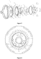
- Figure 1 is an exploded view of an angle adjustment device according to the present application when a damping member is removed;
- Figure 2 is a schematic diagram of a gear mechanism shown in Figure 1 ;
- Figure 3 is an exploded view of the angle adjustment device according to the present application;
- Figure 4 is a top view of the angle adjustment device according to the present application;
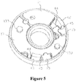
- Figure 5 illustrates the matching relationship between a wedge-shaped block, the damping member, a driving block and an eccentric ring shown in Figure 4 ;
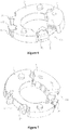
- Figure 6 is a schematic structural view when the eccentric ring shown in Figure 5 is provided with a first damping member;
- Figure 7 is a schematic structural view when the eccentric ring shown in Figure 5 is provided with a second damping member;
- Figure 8 is a schematic structural view when the eccentric ring shown in Figure 5 is provided with a third damping member;
- Figure 9 is a schematic structural view when the damping member is removed in Figure 5 ; and
- Figure 10 is a transverse sectional view of Figure 9 .
- the present application provides an angle adjustment device for an electric seat, as shown in Figure 1 , which includes an inner toothed plate 11 having an inner toothed ring 111 and an outer toothed plate 12 having an outer toothed ring 121, the inner toothed plate 11 is used for being connected with a seat of an electric seat, and the outer toothed plate 12 is used for being connected with a seat back of the electric seat.
- a shaft collar 112 is provided in the middle of the inner toothed plate 11.
- a central hole 122 is formed in the middle of the outer toothed plate 12, the inner toothed plate 11 is eccentrically engaged with the outer toothed plate 12 through the inner toothed ring 111 and the outer toothed ring 121, and an eccentric cavity is formed between the shaft collar 12 and the central hole 122 after engaging.
- An eccentric ring 13 filling a forward eccentric zone of the eccentric cavity is arranged in the eccentric cavity, and the forward eccentric zone refers to a zone with a large inner radial size of the eccentric cavity.
- a gear mechanism 1 is formed by the inner toothed plate 11, the outer toothed plate 12 and the eccentric ring 13, and the gear mechanism 1 is a less-tooth-difference planetary gear transmission mechanism, and on the basis of realizing transmission, the gear mechanism 1 has the advantage of being compact in structure, and can be used for the electric seat.
- the eccentric ring 13 is provided with a first accommodating zone 131 and a second accommodating zone 132 in the circumferential direction, a driving member for driving the eccentric ring 13 to rotate is arranged in the first accommodating zone 131 and/or the second accommodating zone 132, and under the driving of the driving member, the eccentric ring 13 rotates, so that the inner toothed plate 11 rotates with respect to the outer toothed plate 12, thereby realizing the adjustment of the angle between the chair seat and the chair back.
- the driving member achieves the rotation of the eccentric ring 13 by driving the side walls of the first accommodating zone 131 and/or the second accommodating zone 132, however, as shown in Figure 2 , a certain operating idle strokes a and b are formed between the driving member and driving matching surface of the first accommodating zone 131 and/or between the driving member and driving matching surface of the second accommodating zone 132, that is, a certain distance is formed between the driving member and the driving matching surface.
- the driving member needs to pass through the operating idle strokes a and b before abutting against the driving matching surface, and then the driving member can be matched with the driving matching surface.
- the passenger can feel an apparent lag in the adjusting process, which affects the comfort during reversing of the electric seat.
- the driving member is matched with the driving matching surface after passing through the operating idle strokes a and b, the driving member is in contact with the driving matching surface at a high speed, so that a significant noise is generated when the seat and the chair back are reversely adjusted, which also affects the comfort of the electric seat.
- a damping member 15 is further arranged in the first accommodating zone 131 and/or the second accommodating zone 132 in addition to the driving member.
- the damping member 15 can fill the operating idle stroke of the angle adjustment device, so that the damping member 15 is in a compressed state before the driving member is matched with the driving matching surface, and after the driving member is matched with the driving matching surface, the damping member 15 drives the eccentric ring 13 to rotate, thereby achieving the angle adjustment. Therefore, the arrangement of the damping member 15 can eliminate the operating idle stroke, thereby eliminating the adjustment lag felt by passengers during the reversing adjustment process of the seat and the backrest, and the arrangement of the damping member 15 can also consume energy when the driving member is in contact with the driving matching surface, thereby reducing the noise when the seat and the backrest are reversely adjusted, and further improving the comfort of the electric seat.
- a wedge-shaped block 2 is arranged in the first accommodating zone 131 of the eccentric ring 13.
- the driving member drives the eccentric ring 13 to rotate by driving the wedge-shaped block 2.
- the angle adjustment device further includes an elastic member, and the elastic force of the elastic member compresses the eccentric ring 13 and the wedge-shaped block 2.
- the circumferential elastic force applied by the elastic member acts on the eccentric ring 13 and the wedge-shaped block 2, so that the eccentric ring 13 abuts against a hole wall of a central hole 122 of the outer toothed plate 12, and the wedge-shaped block 2 abuts against the shaft collar 112 of the inner toothed plate 11, thereby eliminating the clearance between engaging teeth of the inner toothed ring 111 and the outer toothed ring 121, and further improving the comfort of the electric seat.
- the elastic member can be a torsion spring 3 having two axial legs arranged in the same direction.
- one leg of the torsion spring 3 is mounted into a fixing hole of the wedge-shaped block 2 after passing through a locking hole 53 of a locking plate 5, and the other leg abuts against the inner wall of the wedge-shaped block 2 after passing through the locking hole 53, so that the eccentric ring 13 and the wedge-shaped block 2 are tightly wedged by the torsion spring 3.
- the driving member includes a first driving block 42 extending into the first accommodating zone 131 and a second driving block 43 extending into the second accommodating zone 132, and the two driving blocks are both convex blocks arranged on the end face of a driving wheel 4.
- the first driving block 42 and the second driving block 43 extend into the first accommodating zone 131 and the second accommodating zone 132 of the eccentric ring 13 respectively after passing through the two driving holes 52 of the locking plate 5, and each of two driving blocks is provided with a driving working surface 44 and a non-driving working surface 45 in the circumferential direction.
- the locking plate 5 also has a fixing hole 51 connected with the other members.
- the damping member 15 is arranged in each of the first accommodating zone 131 and the second accommodating zone 132, and the damping member 15 located in the first accommodating zone 131 is a first damping member, and the damping member 15 located in the second accommodating zone 132 is a second damping member.
- one of the two driving blocks is in a driving mode and the other is in a non-driving mode, one end of the damping member 15 in each of the two accommodating zones abuts against the non-driving working surface 45 of the corresponding driving block, and the other end of the damping member 15 abuts against the circumferential side wall of the corresponding accommodating zone.
- the first driving block 42 When the first driving block 42 is a driving end, as shown in Figure 5 , in the process that a rotating shaft 41 drives the driving wheel 4 to rotate, the second driving block 43 moves toward the damping member 15 (the second damping element) and compresses the damping member 15 before the first driving block 42 is in contact with the first driving matching surface 21, and when the damping member 15 (the second damping element) is deformed into that the first driving block 42 can be in contact with the first driving matching surface 21 during compression, the first driving block 42 drives the eccentric ring 13 to rotate by the wedge-shaped block 2.
- the rotating shaft 41 drives the driving wheel 4 to rotate reversely
- the first driving block 42 moves towards the damping member 15 (the first damping element) and compresses the damping member 15 before the second driving block 43 is in contact with the second driving matching surface 135, and when the damping member 15 (the first damping element) is deformed into that the second driving block 43 can be in contact with the second driving matching surface 135 during compression, the second driving block 43 drives the eccentric ring 13 to rotate reversely.
- first accommodating zone 131 is filled with the first driving block 42 and the damping member 15 (the first damping element)
- second accommodating zone 132 is filled with the second driving block 43 and the damping member 15 (the second damping element).
- the size of the damping member 15 by controlling the size of the damping member 15, it can achieve that the driving block and the damping member 15 fill the corresponding accommodating zone as much as possible, so that when the driving block of the driving end is in contact with the corresponding driving matching surface, the required amount of deformation of the damping member 15 is less, thereby prolonging the service life of the damping member 15.
- the operating idle strokes a and b are randomly distributed, both of which may be different or the same, and when the operating idle stroke a and b are different, the eccentric directions of the eccentric ring 13 are different in the two directions, thereby resulting in that driving forces are different when the angle adjustment device is adjusted in two directions.
- the distance between each of the two driving blocks and the corresponding driving matching surface is adjustable, so that the distances can be artificially controlled to be equal to allow the eccentric directions on the two sides of the eccentric ring 13 consistent.
- the damping members 15 in each of the first accommodating zone 131 and the second accommodating zone 132 can be a rubber block, that is, the first damping element and the second damping element are both rubber blocks, and the rubber block is always in an elastic deformation stage during the working process of the angle adjustment device to avoid yielding and crushing, thereby ensuring that the angle adjustment device can work normally.
- the damping member 15 can also be a spring, and in addition, the damping members 15 in the first accommodation zone 131 and the second accommodating zone 132 can be the same or different, that is, the first damping element and the second damping element can be the same structure or different structures, for example: the first damping element is a rubber block, and the second damping element is a spring.
- the damping member 15 in the first accommodating zone 131 and the damping member 15 in the second accommodating zone 132 can also be an integrally formed elastic structure, that is, the first damping element and the second damping element can also be the integrally formed elastic structure, a groove is arranged in the middle of the damping member 15, and the two ends of the groove are respectively located in the two accommodating zones, that is, the two ends of the groove of the damping member 15 form the first damping element and the second damping element, respectively.
- the damping member 15 is buckled on the eccentric ring 13.
- an accommodating groove 14 for engaging with the damping member 15 is provided in the side wall of each of the first accommodating zone 131 and the second accommodating zone 132, and the damping member 15 is arranged in the accommodating groove 14.
- the lubricating oil can be introduced into the angle adjustment device, thereby reducing the abrasion of the members during relative movement, prolonging the service life of the angle adjustment device, and further reducing the noise during working.
- the present application further provides an electric seat which includes a chair seat and a chair back, the chair seat and the chair back are connected through an angle adjustment device, and the angle between the chair seat and the chair back is changed through the angle adjustment device.
- the angle adjustment device is the angle adjustment device according to any one of the above embodiments. Since the angle adjustment device has the above technical effect, the electric seat including the angle adjustment device should also have a corresponding technical effect, which will not be repeated here.
Landscapes
- Engineering & Computer Science (AREA)
- Aviation & Aerospace Engineering (AREA)
- Transportation (AREA)
- Mechanical Engineering (AREA)
- Chairs For Special Purposes, Such As Reclining Chairs (AREA)
- Seats For Vehicles (AREA)
Abstract
Description
- The present application claims the benefits of Chinese patent application No.
201711321068.X 201721748382.1 - The present application relates to the technical field of automobile parts, and in particular to an electric seat and an angle adjustment device for the electric seat.
- A seat angle adjuster is used for connecting a chair seat and a chair back of an automobile seat. Passengers can obtain the most comfortable and accustomed riding angle by adjusting an angle of the chair back to the optimal position through the seat angle adjuster. Drives can obtain the best view by adjusting the angle of the chair back, and can easily manipulate a steering wheel, a pedal, a shift lever and other operating parts by adjusting the angle of the chair back. With the development of the automobile industry, customers' requirements for the angle adjuster and the comfort performance of the seat are gradually improved.
- At present, the electric seat angle adjuster generally adopts a planetary gear transmission principle, and when the members are assembled, due to the existence of a certain degree of processing and assembling errors, there is a certain distance between a driving member and a driving matching surface, and the distance between the driving member and the driving matching surface forms an operating idle stroke of the electric seat angle adjuster.
- Due to the existence of the above operating idle stroke, when the chair seat and the chair back are in reversing operation, the driving member must first pass through the operating idle stroke and then be in contact with the driving matching surface, thereby causing the problems of driving out-of-synchronization, backrest adjustment lag, reversing impact noise and the like in the reversing operation process, and causing the poor comfort of the electric seat.
- In view of this, a technical problem to be solved urgently by those skilled in the art is how to provide an angle adjuster for an electric seat, which can eliminate or reduce the operating idle stroke of the driving member, thereby improving the comfort of the electric seat.
- In order to solve the above technical problem, an object of the present application is to provide an angle adjustment device for an electric seat, which includes an inner toothed plate and an outer toothed plate engaging with each other, an eccentric cavity is formed between the inner toothed plate and the outer toothed plate, an eccentric ring filling a forward eccentric zone of the eccentric cavity is arranged in the eccentric cavity, the eccentric ring is provided with a first accommodating zone and a second accommodating zone in the circumferential direction, and the angle adjustment device for an electric seat further includes a driving member for driving the eccentric ring to rotate. A damping member is arranged in the first accommodating zone and/or the second accommodating zone, and the damping member is in a compressed state during the working of the driving member.
- In the present application, after the damping member is arranged, the damping member can fill the operating idle stroke of the angle adjustment device, so that the damping member is in a compressed state before the driving member is matched with the driving matching surface, and after the driving member is matched with the driving matching surface, the eccentric ring is driven to rotate, achieving the angle adjustment. Therefore, the arrangement of the damping member can eliminate the operating idle stroke described above, thereby eliminating the adjustment lag felt by the passenger during the reversing adjustment process of the seat and the backrest, and the arrangement of the damping member can consume energy when the driving member is in contact with the driving matching surface, thereby reducing the noise during reversing adjustment of the seat and the backrest, and further improving the comfort of the electric seat.
- In one embodiment, a wedge-shaped block is arranged in the first accommodating zone, and the driving member can drive the wedge-shaped block or the eccentric ring to drive the eccentric ring to rotate; and
the angle adjustment device further includes an elastic member for compressing the eccentric ring and the wedge-shaped block. - In one embodiment, the driving member includes a first driving block extending into the first accommodating zone and a second driving block extending into the second accommodating zone, and each of the first driving block and the second driving block has a driving working surface and a non-driving working surface; and
the damping member includes a first damping element arranged in the first accommodating zone and a second damping element arranged in the second accommodating zone, one end of each of the first damping element and the second damping abuts against the non-driving working surface of the relative driving block, and another end of the two damping elements abuts against the side wall of the relative accommodating zone. - In one embodiment, the first accommodating zone is filled with the first driving block and the first damping element, and the second accommodating zone is filled with the second driving block and the second damping element.
- In one embodiment, the first damping element and the second damping element are of separate structures.
- In one embodiment, the first damping element is a rubber block or a spring, and the second damping element is a rubber block or a spring.
- In one embodiment, the damping member is an integrally formed elastic structure and is provided with a groove, the groove is engaged with the eccentric ring, and the first damping element and the second damping element are provide on two sides of the groove, respectively.
- In one embodiment, an accommodating groove for engaging with the relative damping element is provided in a side wall of each of the first accommodating zone and the second accommodating zone.
- In one embodiment, each of the first damping element and the second damping element is of a blocky structure, and an oil guiding groove is arranged in an outer periphery of each of the first damping element and the second damping element.
- In addition, the present application further provides an electric seat which includes a chair seat and a chair back, and the chair seat is connected with the chair back through an angle adjustment device, where the angle adjustment device is the angle adjustment device described above.
-
-
Figure 1 is an exploded view of an angle adjustment device according to the present application when a damping member is removed; -
Figure 2 is a schematic diagram of a gear mechanism shown inFigure 1 ; -
Figure 3 is an exploded view of the angle adjustment device according to the present application; -
Figure 4 is a top view of the angle adjustment device according to the present application; -
Figure 5 illustrates the matching relationship between a wedge-shaped block, the damping member, a driving block and an eccentric ring shown inFigure 4 ; -
Figure 6 is a schematic structural view when the eccentric ring shown inFigure 5 is provided with a first damping member; -
Figure 7 is a schematic structural view when the eccentric ring shown inFigure 5 is provided with a second damping member; -
Figure 8 is a schematic structural view when the eccentric ring shown inFigure 5 is provided with a third damping member; -
Figure 9 is a schematic structural view when the damping member is removed inFigure 5 ; and -
Figure 10 is a transverse sectional view ofFigure 9 . - In order to enable those skilled in the art to better understand the solutions of the present application, the present application is further described in detail hereinafter in conjunction with the accompanying drawings and specific embodiments.
- Referring to
Figures 1 to 10 ,Figure 1 is an exploded view of an angle adjustment device according to the present application when a damping member is removed;Figure 2 is a schematic diagram of a gear mechanism shown inFigure 1 ;Figure 3 is an exploded view of the angle adjustment device according to the present application;Figure 4 is a top view of the angle adjustment device according to the present application;Figure 5 illustrates the matching relationship between a wedge-shaped block, the damping member, a driving block and an eccentric ring shown inFigure 4 ;Figure 6 is a schematic structural view when the eccentric ring shown inFigure 5 is provided with a first damping member;Figure 7 is a schematic structural view when the eccentric ring shown inFigure 5 is provided with a second damping member;Figure 8 is a schematic structural view when the eccentric ring shown inFigure 5 is provided with a third damping member;Figure 9 is a schematic structural view when the damping member is removed inFigure 5 ; andFigure 10 is a transverse sectional view ofFigure 9 . - In a specific embodiment, the present application provides an angle adjustment device for an electric seat, as shown in
Figure 1 , which includes aninner toothed plate 11 having aninner toothed ring 111 and anouter toothed plate 12 having anouter toothed ring 121, theinner toothed plate 11 is used for being connected with a seat of an electric seat, and theouter toothed plate 12 is used for being connected with a seat back of the electric seat. A shaft collar 112 is provided in the middle of theinner toothed plate 11. Acentral hole 122 is formed in the middle of theouter toothed plate 12, the innertoothed plate 11 is eccentrically engaged with the outertoothed plate 12 through the innertoothed ring 111 and theouter toothed ring 121, and an eccentric cavity is formed between theshaft collar 12 and thecentral hole 122 after engaging. Aneccentric ring 13 filling a forward eccentric zone of the eccentric cavity is arranged in the eccentric cavity, and the forward eccentric zone refers to a zone with a large inner radial size of the eccentric cavity. - In the present application, a gear mechanism 1 is formed by the
inner toothed plate 11, theouter toothed plate 12 and theeccentric ring 13, and the gear mechanism 1 is a less-tooth-difference planetary gear transmission mechanism, and on the basis of realizing transmission, the gear mechanism 1 has the advantage of being compact in structure, and can be used for the electric seat. - Specifically, as shown in
Figures 1 and 2 , theeccentric ring 13 is provided with a firstaccommodating zone 131 and a secondaccommodating zone 132 in the circumferential direction, a driving member for driving theeccentric ring 13 to rotate is arranged in thefirst accommodating zone 131 and/or the secondaccommodating zone 132, and under the driving of the driving member, theeccentric ring 13 rotates, so that theinner toothed plate 11 rotates with respect to theouter toothed plate 12, thereby realizing the adjustment of the angle between the chair seat and the chair back. - In the present embodiment, the driving member achieves the rotation of the
eccentric ring 13 by driving the side walls of thefirst accommodating zone 131 and/or the secondaccommodating zone 132, however, as shown inFigure 2 , a certain operating idle strokes a and b are formed between the driving member and driving matching surface of thefirst accommodating zone 131 and/or between the driving member and driving matching surface of the secondaccommodating zone 132, that is, a certain distance is formed between the driving member and the driving matching surface. When the angle adjustment device works, the driving member needs to pass through the operating idle strokes a and b before abutting against the driving matching surface, and then the driving member can be matched with the driving matching surface. - Therefore, in the above angle adjustment device, due to the existence of the operating idle strokes a and b, when the seat and the backrest are reversely adjusted, the passenger can feel an apparent lag in the adjusting process, which affects the comfort during reversing of the electric seat. When the driving member is matched with the driving matching surface after passing through the operating idle strokes a and b, the driving member is in contact with the driving matching surface at a high speed, so that a significant noise is generated when the seat and the chair back are reversely adjusted, which also affects the comfort of the electric seat.
- In order to solve the above technical problem, in the angle adjustment device according to the present application, a
damping member 15 is further arranged in thefirst accommodating zone 131 and/or the secondaccommodating zone 132 in addition to the driving member. - In the present application, after the damping
member 15 is arranged, the dampingmember 15 can fill the operating idle stroke of the angle adjustment device, so that thedamping member 15 is in a compressed state before the driving member is matched with the driving matching surface, and after the driving member is matched with the driving matching surface, the dampingmember 15 drives theeccentric ring 13 to rotate, thereby achieving the angle adjustment. Therefore, the arrangement of the dampingmember 15 can eliminate the operating idle stroke, thereby eliminating the adjustment lag felt by passengers during the reversing adjustment process of the seat and the backrest, and the arrangement of the dampingmember 15 can also consume energy when the driving member is in contact with the driving matching surface, thereby reducing the noise when the seat and the backrest are reversely adjusted, and further improving the comfort of the electric seat. - Further, a wedge-
shaped block 2 is arranged in the firstaccommodating zone 131 of theeccentric ring 13. In the firstaccommodating zone 131, the driving member drives theeccentric ring 13 to rotate by driving the wedge-shaped block 2. The angle adjustment device further includes an elastic member, and the elastic force of the elastic member compresses theeccentric ring 13 and the wedge-shaped block 2. - When the angle adjustment device works, the circumferential elastic force applied by the elastic member acts on the
eccentric ring 13 and the wedge-shaped block 2, so that theeccentric ring 13 abuts against a hole wall of acentral hole 122 of theouter toothed plate 12, and the wedge-shaped block 2 abuts against the shaft collar 112 of theinner toothed plate 11, thereby eliminating the clearance between engaging teeth of theinner toothed ring 111 and theouter toothed ring 121, and further improving the comfort of the electric seat. - Specifically, the elastic member can be a torsion spring 3 having two axial legs arranged in the same direction. During assembly, one leg of the torsion spring 3 is mounted into a fixing hole of the wedge-
shaped block 2 after passing through alocking hole 53 of alocking plate 5, and the other leg abuts against the inner wall of the wedge-shaped block 2 after passing through thelocking hole 53, so that theeccentric ring 13 and the wedge-shaped block 2 are tightly wedged by the torsion spring 3. - Further, as shown in
Figure 5 , the driving member includes afirst driving block 42 extending into thefirst accommodating zone 131 and asecond driving block 43 extending into thesecond accommodating zone 132, and the two driving blocks are both convex blocks arranged on the end face of a driving wheel 4. Specifically, thefirst driving block 42 and thesecond driving block 43 extend into thefirst accommodating zone 131 and the secondaccommodating zone 132 of theeccentric ring 13 respectively after passing through the two driving holes 52 of thelocking plate 5, and each of two driving blocks is provided with a driving workingsurface 44 and a non-driving workingsurface 45 in the circumferential direction. Thelocking plate 5 also has a fixing hole 51 connected with the other members. - In order to further eliminate the operating idle strokes a and b between the driving member and the driving matching surface, the
damping member 15 is arranged in each of thefirst accommodating zone 131 and thesecond accommodating zone 132, and thedamping member 15 located in thefirst accommodating zone 131 is a first damping member, and thedamping member 15 located in thesecond accommodating zone 132 is a second damping member. In the two driving blocks, one of the two driving blocks is in a driving mode and the other is in a non-driving mode, one end of the dampingmember 15 in each of the two accommodating zones abuts against thenon-driving working surface 45 of the corresponding driving block, and the other end of the dampingmember 15 abuts against the circumferential side wall of the corresponding accommodating zone. - Specifically, as shown in
Figures 6 to 9 , in the firstaccommodating zone 131, two ends of the damping member 15 (the first damping element) abut against thefirst driving block 42 and a firstbuffering matching face 134 of the firstaccommodating zone 131 in the circumferential direction, respectively. In the secondaccommodating zone 132, two ends of the damping member 15 (the first damping element) abut against thesecond driving block 43 and a secondbuffering matching face 134 of the secondaccommodating zone 132 in the circumferential direction, respectively. - When the
first driving block 42 is a driving end, as shown inFigure 5 , in the process that a rotating shaft 41 drives the driving wheel 4 to rotate, thesecond driving block 43 moves toward the damping member 15 (the second damping element) and compresses the dampingmember 15 before thefirst driving block 42 is in contact with the firstdriving matching surface 21, and when the damping member 15 (the second damping element) is deformed into that thefirst driving block 42 can be in contact with the firstdriving matching surface 21 during compression, thefirst driving block 42 drives theeccentric ring 13 to rotate by the wedge-shapedblock 2. When thesecond driving block 43 is the driving end, the rotating shaft 41 drives the driving wheel 4 to rotate reversely, thefirst driving block 42 moves towards the damping member 15 (the first damping element) and compresses the dampingmember 15 before thesecond driving block 43 is in contact with the seconddriving matching surface 135, and when the damping member 15 (the first damping element) is deformed into that thesecond driving block 43 can be in contact with the seconddriving matching surface 135 during compression, thesecond driving block 43 drives theeccentric ring 13 to rotate reversely. - In order to achieve the reversing operation, it is necessary to ensure that the damping
member 15 has a sufficient amount of deformation. - Further, the first
accommodating zone 131 is filled with thefirst driving block 42 and the damping member 15 (the first damping element), and the secondaccommodating zone 132 is filled with thesecond driving block 43 and the damping member 15 (the second damping element). - In the present embodiment, by controlling the size of the damping
member 15, it can achieve that the driving block and the dampingmember 15 fill the corresponding accommodating zone as much as possible, so that when the driving block of the driving end is in contact with the corresponding driving matching surface, the required amount of deformation of the dampingmember 15 is less, thereby prolonging the service life of the dampingmember 15. - In addition, as shown in
Figure 2 , when the damping member is not provided, the operating idle strokes a and b are randomly distributed, both of which may be different or the same, and when the operating idle stroke a and b are different, the eccentric directions of theeccentric ring 13 are different in the two directions, thereby resulting in that driving forces are different when the angle adjustment device is adjusted in two directions. - In the present application, as shown in
Figure 10 , by controlling the size of the dampingmembers 15 in the two accommodating zones, the distance between each of the two driving blocks and the corresponding driving matching surface is adjustable, so that the distances can be artificially controlled to be equal to allow the eccentric directions on the two sides of theeccentric ring 13 consistent. - Specifically, as shown in
Figure 6 , the dampingmembers 15 in each of the firstaccommodating zone 131 and the secondaccommodating zone 132 can be a rubber block, that is, the first damping element and the second damping element are both rubber blocks, and the rubber block is always in an elastic deformation stage during the working process of the angle adjustment device to avoid yielding and crushing, thereby ensuring that the angle adjustment device can work normally. - As shown in
Figure 7 , the dampingmember 15 can also be a spring, and in addition, the dampingmembers 15 in thefirst accommodation zone 131 and the secondaccommodating zone 132 can be the same or different, that is, the first damping element and the second damping element can be the same structure or different structures, for example: the first damping element is a rubber block, and the second damping element is a spring. - As shown in
Figure 8 , the dampingmember 15 in the firstaccommodating zone 131 and the dampingmember 15 in the secondaccommodating zone 132 can also be an integrally formed elastic structure, that is, the first damping element and the second damping element can also be the integrally formed elastic structure, a groove is arranged in the middle of the dampingmember 15, and the two ends of the groove are respectively located in the two accommodating zones, that is, the two ends of the groove of the dampingmember 15 form the first damping element and the second damping element, respectively. The dampingmember 15 is buckled on theeccentric ring 13. - Further, as shown in
Figure 9 , in order to improve the mounting reliability of the dampingmember 15, anaccommodating groove 14 for engaging with the dampingmember 15 is provided in the side wall of each of the firstaccommodating zone 131 and the secondaccommodating zone 132, and the dampingmember 15 is arranged in theaccommodating groove 14. - In the above embodiments, as shown in
Figure 6 , when each of the first damping element and the second damping element is of a block structure, anoil guiding groove 151 is provided in the outer periphery of each of the first damping element and the second damping element. - In the present embodiment, by arranging the
oil guide groove 151 in the outer periphery of the dampingmember 15, the lubricating oil can be introduced into the angle adjustment device, thereby reducing the abrasion of the members during relative movement, prolonging the service life of the angle adjustment device, and further reducing the noise during working. - In addition, the present application further provides an electric seat which includes a chair seat and a chair back, the chair seat and the chair back are connected through an angle adjustment device, and the angle between the chair seat and the chair back is changed through the angle adjustment device. The angle adjustment device is the angle adjustment device according to any one of the above embodiments. Since the angle adjustment device has the above technical effect, the electric seat including the angle adjustment device should also have a corresponding technical effect, which will not be repeated here.
- The electric seat and the angle adjustment device thereof according to the present application are described in detail. Although the principles and embodiments of the present application have been described herein with specific examples, the description of the embodiments above is merely intended to aid in the understanding of the methods and core concepts of the present application. It should be noted that multiple improvements and modifications of the present application may be made by those skilled in the art without departing from the principles of the present application, which are also within the scope of the present application defined by the claims.
| 1 | gear mechanism, | 11 | inner toothed plate, |
| 111 | inner toothed ring, | 112 | shaft collar, |
| 12 | outer toothed plate, | 121 | outer toothed ring, |
| 122 | center hole, | 13 | eccentric ring, |
| 131 | first accommodating zone, | 132 | second accommodating zone, |
| 133 | flange, | 134 | first buffering matching face, |
| 135 | second driving matching face, | 136 | second buffering matching face, |
| 14 | accommodating groove, | 15 | damping member, |
| 151 | oil guiding groove; | ||
| 2 | wedge-shaped block, | 21 | first driving matching face, |
| 3 | torsion spring; | ||
| 4 | driving wheel, | 41 | rotating shaft, |
| 42 | first driving block, | 43 | second driving block, |
| 44 | driving work surface, | 45 | non-drive working surface; |
| 5 | locking plate, | 51 | fixing hole, |
| 52 | driving hole, | 53 | locking hole. |
Claims (10)
- An angle adjustment device for an electric seat, comprising an inner toothed plate (11) and an outer toothed plate (12) engaging with each other, an eccentric cavity being formed between the inner toothed plate (11) and the outer toothed plate (12), an eccentric ring (13) filling a forward eccentric zone of the eccentric cavity being arranged in the eccentric cavity, the eccentric ring (13) being provided with a first accommodating zone (131) and a second accommodating zone (132) in a circumferential direction, and the angle adjustment device for an electric seat further comprising a driving member for driving the eccentric ring (13) to rotate; wherein, a damping member (15) is arranged in the first accommodating zone (131) and/or the second accommodating zone (132), and the damping member (15) is in a compressed state during working of the driving member.
- The angle adjustment device according to claim 1, wherein, a wedge-shaped block (2) is arranged in the first accommodating zone (131), and the driving member is configured to drive the wedge-shaped block (2) or the eccentric ring (13) to drive the eccentric ring (13) to rotate; and
the angle adjustment device further comprises an elastic member for compressing the eccentric ring (13) and the wedge-shaped block (2). - The angle adjustment device according to claim 2, wherein, the driving member comprises a first driving block (42) extending into the first accommodating zone (131) and a second driving block (43) extending into the second accommodating zone (132), and each of the first driving block (42) and the second driving block (43) has a driving working surface (44) and a non-driving working surface (45); and
the damping member comprises a first damping element arranged in the first accommodating zone (131) and a second damping element arranged in the second accommodating zone (132), one end of each of the first damping element and the second damping abuts against the non-driving working surface (45) of a relative driving block, and another end of each of the first damping element and the second damping element abuts against a side wall of a relative accommodating zone. - The angle adjustment device according to claim 3, wherein, the first accommodating zone (131) is filled with the first driving block (42) and the first damping element, and the second accommodating zone (132) is filled with the second driving block (43) and the second damping element.
- The angle adjustment device according to claim 3, wherein, the first damping element and the second damping element are of separate structures.
- The angle adjustment device according to claim 5, wherein, the first damping element is a rubber block or a spring, and the second damping element is a rubber block or a spring.
- The angle adjustment device according to claim 3, wherein, the damping member is an integrally formed elastic structure and is provided with a groove, the groove is engaged with the eccentric ring (13), and the first damping element and the second damping element are provided on two sides of the groove, respectively.
- The angle adjustment device according to claim 3, wherein, an accommodating groove (14) for engaging with a relative damping element is provided in a side wall of each of the first accommodating zone (131) and the second accommodating zone (132).
- The angle adjustment device according to claim 3, wherein, each of the first damping element and the second damping element is of a blocky structure, and an oil guiding groove (151) is arranged in an outer periphery of each of the first damping element and the second damping element.
- An electric seat, comprising a chair seat and a chair back, the chair seat being connected to the chair back through an angle adjustment device, wherein the angle adjustment device is the angle adjustment device according to any one of claims 1 to 9.
Applications Claiming Priority (3)
| Application Number | Priority Date | Filing Date | Title |
|---|---|---|---|
| CN201721748382.1U CN207535735U (en) | 2017-12-12 | 2017-12-12 | A kind of automatic seat and its angle regulator |
| CN201711321068.XA CN107933383B (en) | 2017-12-12 | 2017-12-12 | Electric seat and angle adjusting device thereof |
| PCT/CN2018/098498 WO2019114286A1 (en) | 2017-12-12 | 2018-08-03 | Electric seat and angle adjustment device thereof |
Publications (3)
| Publication Number | Publication Date |
|---|---|
| EP3725587A1 true EP3725587A1 (en) | 2020-10-21 |
| EP3725587A4 EP3725587A4 (en) | 2021-09-15 |
| EP3725587B1 EP3725587B1 (en) | 2023-01-04 |
Family
ID=66819513
Family Applications (1)
| Application Number | Title | Priority Date | Filing Date |
|---|---|---|---|
| EP18887742.7A Active EP3725587B1 (en) | 2017-12-12 | 2018-08-03 | Electric seat and angle adjustment device thereof |
Country Status (4)
| Country | Link |
|---|---|
| US (1) | US11312266B2 (en) |
| EP (1) | EP3725587B1 (en) |
| JP (1) | JP7046206B2 (en) |
| WO (1) | WO2019114286A1 (en) |
Families Citing this family (4)
| Publication number | Priority date | Publication date | Assignee | Title |
|---|---|---|---|---|
| CN107933383B (en) * | 2017-12-12 | 2023-09-12 | 湖北中航精机科技有限公司 | Electric seat and angle adjusting device thereof |
| DE102021201575B3 (en) * | 2021-02-18 | 2022-05-05 | Brose Fahrzeugteile SE & Co. Kommanditgesellschaft, Coburg | Adjustment device with an asymmetrically acting brake assembly and vehicle seat with such an adjustment device |
| US12516706B2 (en) * | 2023-03-16 | 2026-01-06 | Feng-Yu Kuan | Rotating shaft braking structure |
| WO2025152047A1 (en) * | 2024-01-16 | 2025-07-24 | 杭州天铭科技股份有限公司 | Joint module, robotic arm, and robot |
Family Cites Families (30)
| Publication number | Priority date | Publication date | Assignee | Title |
|---|---|---|---|---|
| FR2729108B1 (en) * | 1995-01-10 | 1997-03-28 | Faure Bertrand Equipements Sa | ARTICULATION FOR VEHICLE SEAT, AND VEHICLE SEAT PROVIDED WITH SUCH ARTICULATION |
| US6520583B1 (en) * | 2000-08-24 | 2003-02-18 | Fisher Dynamics Corporation | Compact disc recliner |
| BR0205967B1 (en) * | 2001-09-06 | 2012-06-12 | trim for a vehicle seat. | |
| ATE357365T1 (en) * | 2001-09-14 | 2007-04-15 | Jen-Chih Liu | BICYCLE BRAKE |
| KR100442747B1 (en) * | 2002-03-14 | 2004-08-02 | 주식회사다스 | Pumping device of seat for vehicle |
| DE102007007362B4 (en) * | 2007-02-14 | 2009-07-09 | Faurecia Autositze Gmbh | adjustment |
| JP5177134B2 (en) * | 2007-05-08 | 2013-04-03 | トヨタ紡織株式会社 | Connecting device |
| US7878593B2 (en) | 2008-06-23 | 2011-02-01 | Lear Corporation | Anti back drive device for a seat recliner |
| CN101941389B (en) | 2009-07-04 | 2012-06-20 | 湖北中航精机科技股份有限公司 | Seat angle adjuster and seat with angle adjuster |
| KR100956729B1 (en) * | 2009-12-11 | 2010-05-06 | 대원정밀공업(주) | Pumping device for vehicle seat cushion |
| DE102009060344A1 (en) | 2009-12-24 | 2011-06-30 | Sitech Sitztechnik GmbH, 38442 | Adjustment fitting for adjusting inclination of backrest of motor vehicle seat relative to seat part, has wedge segments in direct or indirect connection by damping element to damp relative movements of segments relative to each other |
| FR2963288B1 (en) * | 2010-07-29 | 2014-04-25 | Faurecia Sieges Automobile | JOINT MECHANISM AND VEHICLE SEAT COMPRISING SUCH A MECHANISM. |
| FR2967102B1 (en) * | 2010-11-10 | 2012-12-07 | Faurecia Sieges Automobile | ADJUSTING MECHANISM FOR VEHICLE SEAT |
| CN103129418B (en) * | 2011-11-25 | 2015-03-25 | 湖北中航精机科技有限公司 | Seat angle adjuster and seat thereof |
| JP6067293B2 (en) | 2012-09-19 | 2017-01-25 | デルタ工業株式会社 | Angle adjustment device for seat bracket |
| US9884572B2 (en) * | 2013-03-22 | 2018-02-06 | Ts Tech Co., Ltd. | Braking device |
| FR3006637B1 (en) | 2013-06-10 | 2015-07-17 | Faurecia Sieges Automobile | ARTICULATION MECHANISM AND VEHICLE SEAT COMPRISING SUCH A MECHANISM |
| CN103273859B (en) * | 2013-06-17 | 2015-05-06 | 湖北中航精机科技有限公司 | Seat angle adjuster and oil gathering element |
| DE102013016289B4 (en) * | 2013-07-11 | 2020-11-12 | Adient Luxembourg Holding S.À R.L. | Adjustment drive, in particular height adjustment drive, of a vehicle seat with a safety gear |
| DE102013215073B3 (en) * | 2013-08-01 | 2014-08-28 | Schaeffler Technologies Gmbh & Co. Kg | Sequencer |
| FR3018051B1 (en) * | 2014-03-03 | 2017-07-21 | Faurecia Sieges Automobile | ARTICULATION MECHANISM AND VEHICLE SEAT COMPRISING SUCH A MECHANISM |
| FR3024080B1 (en) * | 2014-07-22 | 2017-06-23 | Faurecia Sieges Automobile | ANGULAR ADJUSTMENT DEVICE FOR VEHICLE SEAT |
| FR3025758B1 (en) * | 2014-09-12 | 2016-10-21 | Faurecia Sieges Automobile | ANGLE ADJUSTING DEVICE NOT REDUCED FOR VEHICLE SEAT |
| CN107429768B (en) * | 2015-07-16 | 2019-07-26 | 提爱思科技股份有限公司 | Brake apparatus |
| KR101791993B1 (en) * | 2016-03-03 | 2017-11-01 | 현대다이모스(주) | Seat pumping device of vehicle |
| JP6682300B2 (en) * | 2016-03-04 | 2020-04-15 | シロキ工業株式会社 | Seat reclining device |
| EP3293041B1 (en) | 2016-09-09 | 2025-04-09 | Hubei Aviation Precision Machinery Technology Co., Ltd. | Angle adjusting device and seat having the same |
| CN106388368B (en) | 2016-09-09 | 2024-01-16 | 湖北中航精机科技有限公司 | Angle adjusting device and seat with same |
| CN107933383B (en) | 2017-12-12 | 2023-09-12 | 湖北中航精机科技有限公司 | Electric seat and angle adjusting device thereof |
| CN207535735U (en) | 2017-12-12 | 2018-06-26 | 湖北航嘉麦格纳座椅系统有限公司 | A kind of automatic seat and its angle regulator |
-
2018
- 2018-08-03 JP JP2020544086A patent/JP7046206B2/en active Active
- 2018-08-03 US US16/767,547 patent/US11312266B2/en active Active
- 2018-08-03 EP EP18887742.7A patent/EP3725587B1/en active Active
- 2018-08-03 WO PCT/CN2018/098498 patent/WO2019114286A1/en not_active Ceased
Also Published As
| Publication number | Publication date |
|---|---|
| US11312266B2 (en) | 2022-04-26 |
| US20210170917A1 (en) | 2021-06-10 |
| WO2019114286A1 (en) | 2019-06-20 |
| BR112020011282A2 (en) | 2020-11-17 |
| EP3725587A4 (en) | 2021-09-15 |
| EP3725587B1 (en) | 2023-01-04 |
| JP7046206B2 (en) | 2022-04-01 |
| JP2021502304A (en) | 2021-01-28 |
Similar Documents
| Publication | Publication Date | Title |
|---|---|---|
| US11312266B2 (en) | Electric seat and angle adjustment device thereof | |
| US9376035B2 (en) | Seat angle regulator and seat with same | |
| CN101734276B (en) | Rack bar supporting device and vehicle steering apparatus with the same | |
| KR101003718B1 (en) | Stepless adjustable recliner for car seats | |
| CN105358367A (en) | Rotary operation control mechanism and seat | |
| CN207535735U (en) | A kind of automatic seat and its angle regulator | |
| CN110936861B (en) | Concentric adjustment seat angle adjuster | |
| US20080272639A1 (en) | Gear-Driven Adjusting Assembly for Continuous Adjustment of Seat Angle | |
| US12162383B2 (en) | Brake device for power swivel seat | |
| KR20140068662A (en) | Reclining apparatus for seat of vehicle | |
| KR101635354B1 (en) | Device recliner for vehicle | |
| KR101613449B1 (en) | Device recliner for vehicle | |
| CN108528280B (en) | Vehicle seat and electric rotating device thereof | |
| KR20230133637A (en) | Brake apparatus for vehicle | |
| KR101058472B1 (en) | Car Reclining Device | |
| CN107933383B (en) | Electric seat and angle adjusting device thereof | |
| CN114851925A (en) | Seat height adjuster and seat height adjusting device | |
| JP2545309B2 (en) | Planetary gear reducer | |
| CN116490704A (en) | Eccentric transmission mechanism for brake force generator, brake force generator | |
| CN219564849U (en) | Seat height adjuster and seat height adjusting device | |
| CN118082641A (en) | An angle adjustment device for a planetary system with small tooth difference | |
| CN114901540A (en) | Worm gear and worm transmission mechanism | |
| KR101512049B1 (en) | Gear housing of geared motor to reduce starting noise | |
| US11614128B2 (en) | Clutch structure | |
| CN210830408U (en) | Motor and driving wheel mounting structure thereof |
Legal Events
| Date | Code | Title | Description |
|---|---|---|---|
| STAA | Information on the status of an ep patent application or granted ep patent |
Free format text: STATUS: THE INTERNATIONAL PUBLICATION HAS BEEN MADE |
|
| PUAI | Public reference made under article 153(3) epc to a published international application that has entered the european phase |
Free format text: ORIGINAL CODE: 0009012 |
|
| STAA | Information on the status of an ep patent application or granted ep patent |
Free format text: STATUS: REQUEST FOR EXAMINATION WAS MADE |
|
| 17P | Request for examination filed |
Effective date: 20200526 |
|
| AK | Designated contracting states |
Kind code of ref document: A1 Designated state(s): AL AT BE BG CH CY CZ DE DK EE ES FI FR GB GR HR HU IE IS IT LI LT LU LV MC MK MT NL NO PL PT RO RS SE SI SK SM TR |
|
| AX | Request for extension of the european patent |
Extension state: BA ME |
|
| DAV | Request for validation of the european patent (deleted) | ||
| DAX | Request for extension of the european patent (deleted) | ||
| RAP1 | Party data changed (applicant data changed or rights of an application transferred) |
Owner name: HUBEI AVIATION PRECISION MACHINERY TECHNOLOGY CO., LTD. |
|
| RAP3 | Party data changed (applicant data changed or rights of an application transferred) |
Owner name: HUBEI AVIATION PRECISION MACHINERY TECHNOLOGY CO., LTD. |
|
| A4 | Supplementary search report drawn up and despatched |
Effective date: 20210812 |
|
| RIC1 | Information provided on ipc code assigned before grant |
Ipc: B60N 2/225 20060101ALI20210806BHEP Ipc: B60N 2/22 20060101AFI20210806BHEP |
|
| GRAP | Despatch of communication of intention to grant a patent |
Free format text: ORIGINAL CODE: EPIDOSNIGR1 |
|
| STAA | Information on the status of an ep patent application or granted ep patent |
Free format text: STATUS: GRANT OF PATENT IS INTENDED |
|
| INTG | Intention to grant announced |
Effective date: 20220721 |
|
| GRAS | Grant fee paid |
Free format text: ORIGINAL CODE: EPIDOSNIGR3 |
|
| GRAA | (expected) grant |
Free format text: ORIGINAL CODE: 0009210 |
|
| STAA | Information on the status of an ep patent application or granted ep patent |
Free format text: STATUS: THE PATENT HAS BEEN GRANTED |
|
| AK | Designated contracting states |
Kind code of ref document: B1 Designated state(s): AL AT BE BG CH CY CZ DE DK EE ES FI FR GB GR HR HU IE IS IT LI LT LU LV MC MK MT NL NO PL PT RO RS SE SI SK SM TR |
|
| REG | Reference to a national code |
Ref country code: GB Ref legal event code: FG4D |
|
| REG | Reference to a national code |
Ref country code: CH Ref legal event code: EP |
|
| REG | Reference to a national code |
Ref country code: AT Ref legal event code: REF Ref document number: 1541708 Country of ref document: AT Kind code of ref document: T Effective date: 20230115 |
|
| REG | Reference to a national code |
Ref country code: DE Ref legal event code: R096 Ref document number: 602018045181 Country of ref document: DE |
|
| REG | Reference to a national code |
Ref country code: IE Ref legal event code: FG4D |
|
| REG | Reference to a national code |
Ref country code: LT Ref legal event code: MG9D |
|
| REG | Reference to a national code |
Ref country code: NL Ref legal event code: MP Effective date: 20230104 |
|
| REG | Reference to a national code |
Ref country code: AT Ref legal event code: MK05 Ref document number: 1541708 Country of ref document: AT Kind code of ref document: T Effective date: 20230104 |
|
| PG25 | Lapsed in a contracting state [announced via postgrant information from national office to epo] |
Ref country code: NL Free format text: LAPSE BECAUSE OF FAILURE TO SUBMIT A TRANSLATION OF THE DESCRIPTION OR TO PAY THE FEE WITHIN THE PRESCRIBED TIME-LIMIT Effective date: 20230104 |
|
| PG25 | Lapsed in a contracting state [announced via postgrant information from national office to epo] |
Ref country code: RS Free format text: LAPSE BECAUSE OF FAILURE TO SUBMIT A TRANSLATION OF THE DESCRIPTION OR TO PAY THE FEE WITHIN THE PRESCRIBED TIME-LIMIT Effective date: 20230104 Ref country code: PT Free format text: LAPSE BECAUSE OF FAILURE TO SUBMIT A TRANSLATION OF THE DESCRIPTION OR TO PAY THE FEE WITHIN THE PRESCRIBED TIME-LIMIT Effective date: 20230504 Ref country code: NO Free format text: LAPSE BECAUSE OF FAILURE TO SUBMIT A TRANSLATION OF THE DESCRIPTION OR TO PAY THE FEE WITHIN THE PRESCRIBED TIME-LIMIT Effective date: 20230404 Ref country code: LV Free format text: LAPSE BECAUSE OF FAILURE TO SUBMIT A TRANSLATION OF THE DESCRIPTION OR TO PAY THE FEE WITHIN THE PRESCRIBED TIME-LIMIT Effective date: 20230104 Ref country code: LT Free format text: LAPSE BECAUSE OF FAILURE TO SUBMIT A TRANSLATION OF THE DESCRIPTION OR TO PAY THE FEE WITHIN THE PRESCRIBED TIME-LIMIT Effective date: 20230104 Ref country code: HR Free format text: LAPSE BECAUSE OF FAILURE TO SUBMIT A TRANSLATION OF THE DESCRIPTION OR TO PAY THE FEE WITHIN THE PRESCRIBED TIME-LIMIT Effective date: 20230104 Ref country code: ES Free format text: LAPSE BECAUSE OF FAILURE TO SUBMIT A TRANSLATION OF THE DESCRIPTION OR TO PAY THE FEE WITHIN THE PRESCRIBED TIME-LIMIT Effective date: 20230104 Ref country code: AT Free format text: LAPSE BECAUSE OF FAILURE TO SUBMIT A TRANSLATION OF THE DESCRIPTION OR TO PAY THE FEE WITHIN THE PRESCRIBED TIME-LIMIT Effective date: 20230104 |
|
| PG25 | Lapsed in a contracting state [announced via postgrant information from national office to epo] |
Ref country code: SE Free format text: LAPSE BECAUSE OF FAILURE TO SUBMIT A TRANSLATION OF THE DESCRIPTION OR TO PAY THE FEE WITHIN THE PRESCRIBED TIME-LIMIT Effective date: 20230104 Ref country code: PL Free format text: LAPSE BECAUSE OF FAILURE TO SUBMIT A TRANSLATION OF THE DESCRIPTION OR TO PAY THE FEE WITHIN THE PRESCRIBED TIME-LIMIT Effective date: 20230104 Ref country code: IS Free format text: LAPSE BECAUSE OF FAILURE TO SUBMIT A TRANSLATION OF THE DESCRIPTION OR TO PAY THE FEE WITHIN THE PRESCRIBED TIME-LIMIT Effective date: 20230504 Ref country code: GR Free format text: LAPSE BECAUSE OF FAILURE TO SUBMIT A TRANSLATION OF THE DESCRIPTION OR TO PAY THE FEE WITHIN THE PRESCRIBED TIME-LIMIT Effective date: 20230405 Ref country code: FI Free format text: LAPSE BECAUSE OF FAILURE TO SUBMIT A TRANSLATION OF THE DESCRIPTION OR TO PAY THE FEE WITHIN THE PRESCRIBED TIME-LIMIT Effective date: 20230104 |
|
| REG | Reference to a national code |
Ref country code: DE Ref legal event code: R097 Ref document number: 602018045181 Country of ref document: DE |
|
| PG25 | Lapsed in a contracting state [announced via postgrant information from national office to epo] |
Ref country code: SM Free format text: LAPSE BECAUSE OF FAILURE TO SUBMIT A TRANSLATION OF THE DESCRIPTION OR TO PAY THE FEE WITHIN THE PRESCRIBED TIME-LIMIT Effective date: 20230104 Ref country code: RO Free format text: LAPSE BECAUSE OF FAILURE TO SUBMIT A TRANSLATION OF THE DESCRIPTION OR TO PAY THE FEE WITHIN THE PRESCRIBED TIME-LIMIT Effective date: 20230104 Ref country code: EE Free format text: LAPSE BECAUSE OF FAILURE TO SUBMIT A TRANSLATION OF THE DESCRIPTION OR TO PAY THE FEE WITHIN THE PRESCRIBED TIME-LIMIT Effective date: 20230104 Ref country code: DK Free format text: LAPSE BECAUSE OF FAILURE TO SUBMIT A TRANSLATION OF THE DESCRIPTION OR TO PAY THE FEE WITHIN THE PRESCRIBED TIME-LIMIT Effective date: 20230104 Ref country code: CZ Free format text: LAPSE BECAUSE OF FAILURE TO SUBMIT A TRANSLATION OF THE DESCRIPTION OR TO PAY THE FEE WITHIN THE PRESCRIBED TIME-LIMIT Effective date: 20230104 |
|
| PLBE | No opposition filed within time limit |
Free format text: ORIGINAL CODE: 0009261 |
|
| STAA | Information on the status of an ep patent application or granted ep patent |
Free format text: STATUS: NO OPPOSITION FILED WITHIN TIME LIMIT |
|
| PG25 | Lapsed in a contracting state [announced via postgrant information from national office to epo] |
Ref country code: SK Free format text: LAPSE BECAUSE OF FAILURE TO SUBMIT A TRANSLATION OF THE DESCRIPTION OR TO PAY THE FEE WITHIN THE PRESCRIBED TIME-LIMIT Effective date: 20230104 |
|
| 26N | No opposition filed |
Effective date: 20231005 |
|
| PG25 | Lapsed in a contracting state [announced via postgrant information from national office to epo] |
Ref country code: SI Free format text: LAPSE BECAUSE OF FAILURE TO SUBMIT A TRANSLATION OF THE DESCRIPTION OR TO PAY THE FEE WITHIN THE PRESCRIBED TIME-LIMIT Effective date: 20230104 |
|
| PG25 | Lapsed in a contracting state [announced via postgrant information from national office to epo] |
Ref country code: MC Free format text: LAPSE BECAUSE OF FAILURE TO SUBMIT A TRANSLATION OF THE DESCRIPTION OR TO PAY THE FEE WITHIN THE PRESCRIBED TIME-LIMIT Effective date: 20230104 |
|
| REG | Reference to a national code |
Ref country code: CH Ref legal event code: PL |
|
| PG25 | Lapsed in a contracting state [announced via postgrant information from national office to epo] |
Ref country code: MC Free format text: LAPSE BECAUSE OF FAILURE TO SUBMIT A TRANSLATION OF THE DESCRIPTION OR TO PAY THE FEE WITHIN THE PRESCRIBED TIME-LIMIT Effective date: 20230104 |
|
| PG25 | Lapsed in a contracting state [announced via postgrant information from national office to epo] |
Ref country code: LU Free format text: LAPSE BECAUSE OF NON-PAYMENT OF DUE FEES Effective date: 20230803 |
|
| GBPC | Gb: european patent ceased through non-payment of renewal fee |
Effective date: 20230803 |
|
| PG25 | Lapsed in a contracting state [announced via postgrant information from national office to epo] |
Ref country code: LU Free format text: LAPSE BECAUSE OF NON-PAYMENT OF DUE FEES Effective date: 20230803 Ref country code: CH Free format text: LAPSE BECAUSE OF NON-PAYMENT OF DUE FEES Effective date: 20230831 |
|
| REG | Reference to a national code |
Ref country code: BE Ref legal event code: MM Effective date: 20230831 |
|
| REG | Reference to a national code |
Ref country code: IE Ref legal event code: MM4A |
|
| PG25 | Lapsed in a contracting state [announced via postgrant information from national office to epo] |
Ref country code: IT Free format text: LAPSE BECAUSE OF FAILURE TO SUBMIT A TRANSLATION OF THE DESCRIPTION OR TO PAY THE FEE WITHIN THE PRESCRIBED TIME-LIMIT Effective date: 20230104 |
|
| PG25 | Lapsed in a contracting state [announced via postgrant information from national office to epo] |
Ref country code: IE Free format text: LAPSE BECAUSE OF NON-PAYMENT OF DUE FEES Effective date: 20230803 |
|
| PG25 | Lapsed in a contracting state [announced via postgrant information from national office to epo] |
Ref country code: GB Free format text: LAPSE BECAUSE OF NON-PAYMENT OF DUE FEES Effective date: 20230803 |
|
| PG25 | Lapsed in a contracting state [announced via postgrant information from national office to epo] |
Ref country code: IE Free format text: LAPSE BECAUSE OF NON-PAYMENT OF DUE FEES Effective date: 20230803 Ref country code: GB Free format text: LAPSE BECAUSE OF NON-PAYMENT OF DUE FEES Effective date: 20230803 |
|
| PG25 | Lapsed in a contracting state [announced via postgrant information from national office to epo] |
Ref country code: BE Free format text: LAPSE BECAUSE OF NON-PAYMENT OF DUE FEES Effective date: 20230831 |
|
| PG25 | Lapsed in a contracting state [announced via postgrant information from national office to epo] |
Ref country code: BG Free format text: LAPSE BECAUSE OF FAILURE TO SUBMIT A TRANSLATION OF THE DESCRIPTION OR TO PAY THE FEE WITHIN THE PRESCRIBED TIME-LIMIT Effective date: 20230104 |
|
| PG25 | Lapsed in a contracting state [announced via postgrant information from national office to epo] |
Ref country code: BG Free format text: LAPSE BECAUSE OF FAILURE TO SUBMIT A TRANSLATION OF THE DESCRIPTION OR TO PAY THE FEE WITHIN THE PRESCRIBED TIME-LIMIT Effective date: 20230104 |
|
| PG25 | Lapsed in a contracting state [announced via postgrant information from national office to epo] |
Ref country code: CY Free format text: LAPSE BECAUSE OF FAILURE TO SUBMIT A TRANSLATION OF THE DESCRIPTION OR TO PAY THE FEE WITHIN THE PRESCRIBED TIME-LIMIT; INVALID AB INITIO Effective date: 20180803 |
|
| PG25 | Lapsed in a contracting state [announced via postgrant information from national office to epo] |
Ref country code: HU Free format text: LAPSE BECAUSE OF FAILURE TO SUBMIT A TRANSLATION OF THE DESCRIPTION OR TO PAY THE FEE WITHIN THE PRESCRIBED TIME-LIMIT; INVALID AB INITIO Effective date: 20180803 |
|
| PGFP | Annual fee paid to national office [announced via postgrant information from national office to epo] |
Ref country code: DE Payment date: 20250826 Year of fee payment: 8 |
|
| PGFP | Annual fee paid to national office [announced via postgrant information from national office to epo] |
Ref country code: FR Payment date: 20250828 Year of fee payment: 8 |
|
| PG25 | Lapsed in a contracting state [announced via postgrant information from national office to epo] |
Ref country code: TR Free format text: LAPSE BECAUSE OF FAILURE TO SUBMIT A TRANSLATION OF THE DESCRIPTION OR TO PAY THE FEE WITHIN THE PRESCRIBED TIME-LIMIT Effective date: 20230104 |