EP3725457A1 - Turbine casing component and repair method therefor - Google Patents
Turbine casing component and repair method therefor Download PDFInfo
- Publication number
- EP3725457A1 EP3725457A1 EP19461528.2A EP19461528A EP3725457A1 EP 3725457 A1 EP3725457 A1 EP 3725457A1 EP 19461528 A EP19461528 A EP 19461528A EP 3725457 A1 EP3725457 A1 EP 3725457A1
- Authority
- EP
- European Patent Office
- Prior art keywords
- layer
- butter
- casing component
- nickel
- turbine
- Prior art date
- Legal status (The legal status is an assumption and is not a legal conclusion. Google has not performed a legal analysis and makes no representation as to the accuracy of the status listed.)
- Granted
Links
Images


Classifications
-
- F—MECHANICAL ENGINEERING; LIGHTING; HEATING; WEAPONS; BLASTING
- F01—MACHINES OR ENGINES IN GENERAL; ENGINE PLANTS IN GENERAL; STEAM ENGINES
- F01D—NON-POSITIVE DISPLACEMENT MACHINES OR ENGINES, e.g. STEAM TURBINES
- F01D25/00—Component parts, details, or accessories, not provided for in, or of interest apart from, other groups
- F01D25/005—Selecting particular materials
-
- B—PERFORMING OPERATIONS; TRANSPORTING
- B23—MACHINE TOOLS; METAL-WORKING NOT OTHERWISE PROVIDED FOR
- B23K—SOLDERING OR UNSOLDERING; WELDING; CLADDING OR PLATING BY SOLDERING OR WELDING; CUTTING BY APPLYING HEAT LOCALLY, e.g. FLAME CUTTING; WORKING BY LASER BEAM
- B23K35/00—Rods, electrodes, materials, or media, for use in soldering, welding, or cutting
- B23K35/22—Rods, electrodes, materials, or media, for use in soldering, welding, or cutting characterised by the composition or nature of the material
- B23K35/24—Selection of soldering or welding materials proper
- B23K35/30—Selection of soldering or welding materials proper with the principal constituent melting at less than 1550°C
- B23K35/3033—Ni as the principal constituent
-
- B—PERFORMING OPERATIONS; TRANSPORTING
- B23—MACHINE TOOLS; METAL-WORKING NOT OTHERWISE PROVIDED FOR
- B23P—METAL-WORKING NOT OTHERWISE PROVIDED FOR; COMBINED OPERATIONS; UNIVERSAL MACHINE TOOLS
- B23P6/00—Restoring or reconditioning objects
- B23P6/002—Repairing turbine components, e.g. moving or stationary blades, rotors
- B23P6/007—Repairing turbine components, e.g. moving or stationary blades, rotors using only additive methods, e.g. build-up welding
-
- B—PERFORMING OPERATIONS; TRANSPORTING
- B32—LAYERED PRODUCTS
- B32B—LAYERED PRODUCTS, i.e. PRODUCTS BUILT-UP OF STRATA OF FLAT OR NON-FLAT, e.g. CELLULAR OR HONEYCOMB, FORM
- B32B15/00—Layered products comprising a layer of metal
- B32B15/01—Layered products comprising a layer of metal all layers being exclusively metallic
-
- B—PERFORMING OPERATIONS; TRANSPORTING
- B32—LAYERED PRODUCTS
- B32B—LAYERED PRODUCTS, i.e. PRODUCTS BUILT-UP OF STRATA OF FLAT OR NON-FLAT, e.g. CELLULAR OR HONEYCOMB, FORM
- B32B15/00—Layered products comprising a layer of metal
- B32B15/01—Layered products comprising a layer of metal all layers being exclusively metallic
- B32B15/013—Layered products comprising a layer of metal all layers being exclusively metallic one layer being formed of an iron alloy or steel, another layer being formed of a metal other than iron or aluminium
-
- C—CHEMISTRY; METALLURGY
- C22—METALLURGY; FERROUS OR NON-FERROUS ALLOYS; TREATMENT OF ALLOYS OR NON-FERROUS METALS
- C22C—ALLOYS
- C22C37/00—Cast-iron alloys
- C22C37/04—Cast-iron alloys containing spheroidal graphite
-
- F—MECHANICAL ENGINEERING; LIGHTING; HEATING; WEAPONS; BLASTING
- F01—MACHINES OR ENGINES IN GENERAL; ENGINE PLANTS IN GENERAL; STEAM ENGINES
- F01D—NON-POSITIVE DISPLACEMENT MACHINES OR ENGINES, e.g. STEAM TURBINES
- F01D11/00—Preventing or minimising internal leakage of working-fluid, e.g. between stages
- F01D11/08—Preventing or minimising internal leakage of working-fluid, e.g. between stages for sealing space between rotor blade tips and stator
-
- F—MECHANICAL ENGINEERING; LIGHTING; HEATING; WEAPONS; BLASTING
- F01—MACHINES OR ENGINES IN GENERAL; ENGINE PLANTS IN GENERAL; STEAM ENGINES
- F01D—NON-POSITIVE DISPLACEMENT MACHINES OR ENGINES, e.g. STEAM TURBINES
- F01D25/00—Component parts, details, or accessories, not provided for in, or of interest apart from, other groups
- F01D25/24—Casings; Casing parts, e.g. diaphragms, casing fastenings
-
- F—MECHANICAL ENGINEERING; LIGHTING; HEATING; WEAPONS; BLASTING
- F01—MACHINES OR ENGINES IN GENERAL; ENGINE PLANTS IN GENERAL; STEAM ENGINES
- F01D—NON-POSITIVE DISPLACEMENT MACHINES OR ENGINES, e.g. STEAM TURBINES
- F01D5/00—Blades; Blade-carrying members; Heating, heat-insulating, cooling or antivibration means on the blades or the members
- F01D5/005—Repairing methods or devices
-
- B—PERFORMING OPERATIONS; TRANSPORTING
- B23—MACHINE TOOLS; METAL-WORKING NOT OTHERWISE PROVIDED FOR
- B23K—SOLDERING OR UNSOLDERING; WELDING; CLADDING OR PLATING BY SOLDERING OR WELDING; CUTTING BY APPLYING HEAT LOCALLY, e.g. FLAME CUTTING; WORKING BY LASER BEAM
- B23K2101/00—Articles made by soldering, welding or cutting
- B23K2101/001—Turbines
-
- C—CHEMISTRY; METALLURGY
- C21—METALLURGY OF IRON
- C21D—MODIFYING THE PHYSICAL STRUCTURE OF FERROUS METALS; GENERAL DEVICES FOR HEAT TREATMENT OF FERROUS OR NON-FERROUS METALS OR ALLOYS; MAKING METAL MALLEABLE, e.g. BY DECARBURISATION OR TEMPERING
- C21D2251/00—Treating composite or clad material
-
- C—CHEMISTRY; METALLURGY
- C22—METALLURGY; FERROUS OR NON-FERROUS ALLOYS; TREATMENT OF ALLOYS OR NON-FERROUS METALS
- C22C—ALLOYS
- C22C19/00—Alloys based on nickel or cobalt
- C22C19/03—Alloys based on nickel or cobalt based on nickel
-
- F—MECHANICAL ENGINEERING; LIGHTING; HEATING; WEAPONS; BLASTING
- F05—INDEXING SCHEMES RELATING TO ENGINES OR PUMPS IN VARIOUS SUBCLASSES OF CLASSES F01-F04
- F05D—INDEXING SCHEME FOR ASPECTS RELATING TO NON-POSITIVE-DISPLACEMENT MACHINES OR ENGINES, GAS-TURBINES OR JET-PROPULSION PLANTS
- F05D2230/00—Manufacture
- F05D2230/20—Manufacture essentially without removing material
- F05D2230/23—Manufacture essentially without removing material by permanently joining parts together
- F05D2230/232—Manufacture essentially without removing material by permanently joining parts together by welding
- F05D2230/233—Electron beam welding
-
- F—MECHANICAL ENGINEERING; LIGHTING; HEATING; WEAPONS; BLASTING
- F05—INDEXING SCHEMES RELATING TO ENGINES OR PUMPS IN VARIOUS SUBCLASSES OF CLASSES F01-F04
- F05D—INDEXING SCHEME FOR ASPECTS RELATING TO NON-POSITIVE-DISPLACEMENT MACHINES OR ENGINES, GAS-TURBINES OR JET-PROPULSION PLANTS
- F05D2230/00—Manufacture
- F05D2230/30—Manufacture with deposition of material
- F05D2230/31—Layer deposition
-
- F—MECHANICAL ENGINEERING; LIGHTING; HEATING; WEAPONS; BLASTING
- F05—INDEXING SCHEMES RELATING TO ENGINES OR PUMPS IN VARIOUS SUBCLASSES OF CLASSES F01-F04
- F05D—INDEXING SCHEME FOR ASPECTS RELATING TO NON-POSITIVE-DISPLACEMENT MACHINES OR ENGINES, GAS-TURBINES OR JET-PROPULSION PLANTS
- F05D2230/00—Manufacture
- F05D2230/80—Repairing, retrofitting or upgrading methods
-
- F—MECHANICAL ENGINEERING; LIGHTING; HEATING; WEAPONS; BLASTING
- F05—INDEXING SCHEMES RELATING TO ENGINES OR PUMPS IN VARIOUS SUBCLASSES OF CLASSES F01-F04
- F05D—INDEXING SCHEME FOR ASPECTS RELATING TO NON-POSITIVE-DISPLACEMENT MACHINES OR ENGINES, GAS-TURBINES OR JET-PROPULSION PLANTS
- F05D2300/00—Materials; Properties thereof
- F05D2300/10—Metals, alloys or intermetallic compounds
- F05D2300/11—Iron
- F05D2300/111—Cast iron
-
- F—MECHANICAL ENGINEERING; LIGHTING; HEATING; WEAPONS; BLASTING
- F05—INDEXING SCHEMES RELATING TO ENGINES OR PUMPS IN VARIOUS SUBCLASSES OF CLASSES F01-F04
- F05D—INDEXING SCHEME FOR ASPECTS RELATING TO NON-POSITIVE-DISPLACEMENT MACHINES OR ENGINES, GAS-TURBINES OR JET-PROPULSION PLANTS
- F05D2300/00—Materials; Properties thereof
- F05D2300/10—Metals, alloys or intermetallic compounds
- F05D2300/17—Alloys
- F05D2300/171—Steel alloys
Definitions
- the present disclosure relates generally to turbine or turbomachine casing components and more specifically to the material composition, construction and repair methods therefor.
- Nodular cast iron such as ductile cast iron grade GGG40 (DIN)
- DIN ductile cast iron grade GGG40
- Casings are usually large and cast in non-serial production. This often leads to casting defects, as the process is not fully optimized. Furthermore, the casting can be damaged during machining due to damaged cutting tools or incorrect process settings.
- Turbine casings are exposed to high mechanical loads during operation. Vibrations can lead to material fatigue and thus to the formation of cracks. Thermal stresses occur during start and stop sequences of the gas turbine. These temperature fluctuations and the concomitant expansion and contraction of the housing/casing can contribute to the formation of cracks and promotes the spread of existing cracks. If the cracks exceed design limits, the casings may be scrapped and new casings are required, which leads to high cost not only due to the manufacturing cost but also due to the delay in starting operation of the turbine. If possible, the defective castings are repaired mechanically and less often by welding due to the difficulty in the process. The welds often crack during the welding process, upon cooling or shortly during service time.
- Hot welding comprises of depositing nodular cast iron material in the defective area. This process requires high preheat, 594°C (1,100°F) or higher, that may lead to deformation of the casing. For that reason, hot welding cannot be performed on finish machined parts.
- Cold welding involves using welding wire or electrode made of Ni, Ni-Fe or Ni-Fe-Mn alloy. The Ni alloy usually have lower strength than nodular cast iron. Ni-Fe and Ni-Fe-Mn alloys match the strength of nodular cast iron but those alloys have very low coefficient of thermal expansion (CTE). It makes the welding easier, however in large repairs will likely lead to failure during thermal cycling of the casing due to the increased stresses from the CTE mismatch.
- CTE coefficient of thermal expansion
- a casing component is part of a gas or steam turbine.
- the casing component includes a base made of nodular cast iron, and a repaired region in the base.
- the repaired region includes a butter layer applied on the base and a filling layer applied on the butter layer.
- a method for repairing a casing component that is part of a gas or steam turbine includes a step for applying a butter layer on a base material.
- the butter layer is applied with a first interpass temperature.
- a second step applies a fill layer on the butter layer, and the fill layer is applied with a second interpass temperature.
- the first interpass temperature is lower than the second interpass temperature.
- FIG. 1 illustrates a section of an axial flow steam turbine to which exemplary embodiments may be applied. Shown is a casing component 10, a steam flow path 22 and a last stage 20 comprising a stationary vane row 16 and a downstream rotating blade row 18.
- the casing component 10 forms a radial outer limit of the axial steam flow path 22, thereby in part defining the axial steam flow path 22.
- the casing component 10 may additionally provide a carrier means for carrying one or more stationary vane rows 16.
- the casing component 10 may form only a portion of the casing of the steam turbine. That is, the casing component 10 is one component of several components. Alternatively, the casing component 10 may define the casing of the steam turbine.
- stationary vane rows 16 that are each followed downstream, that is an axial direction corresponding to the nominal flow direction or working fluid through the flow path 22, by rotating blade rows 18.
- the last vane row 16 / blade row 18 combination contained within the flow path 22 defines the last stage 20 of the turbine.
- the casing component 10 comprises a base 12 made of nodular cast iron (or ductile iron) and a repaired region 14 that is located the base 12 in a region exposed to the steam flow path 22.
- the repaired region 14 consists of a butter layer underlying a filler or fill layer.
- the repaired region 14 is located in a region radially between the rotating blade row 18 and the base 12, wherein the radial direction is defined at the direction perpendicular to the rotational axis of the rotating blade row 18.
- the repaired region 14 may be located anywhere in or on casing 10.
- FIG. 3 illustrates a sectional view of a repaired region 14 that includes one or more butter layers 32 and a fill layer 34, according to an aspect of the present disclosure.
- the substrate or base 12 is comprised of nodular cast iron, which may also be referred to as ductile iron, ductile cast iron, spheroidal graphite iron, or spheroidal graphite cast iron.
- nodular cast iron which may also be referred to as ductile iron, ductile cast iron, spheroidal graphite iron, or spheroidal graphite cast iron.
- graphite In ductile or nodule cast irons, graphite is in the form of spheres or nodules rather than flakes as in grey iron. In grey iron, sharp graphite flakes create stress concentration points within the metal matrix.
- the rounded or spherical nodules in nodular cast iron inhibit the creation of cracks, providing enhanced ductility and superior mechanical properties.
- region 14 may take the form of a cavity or recess, and this recess may be further excavated to provide a stable base on which to build the repair.
- the substrate or component may then be subjected to an optional pre-heating step, where the substrate is heated to a maximum of 204°C (400°F). This optional heating step is to facilitate the removal of undesired moisture levels.
- Each butter layer 32 may be comprised of nickel, a nickel alloy, a nickel iron alloy or a nickel iron manganese alloy.
- the butter layers 32 are relatively soft and do not form a brittle microstructure due to the large carbon pickup from the cast iron base 14.
- the butter layers 32 are preferably applied with low heat input, an interpass temperature less than 204°C (400°F) and low to no preheat. Interpass temperature is the temperature of the weld site at which subsequent weld runs are deposited, and a specific maximum interpass temperature is selected to control weld metal microstructural development and to minimize the risk of solidification or liquation cracking for austenitic nickel and nickel alloys. A welder must wait for the weld site to cool before making another pass, if the local temperature is above the desired interpass temperature.
- a fill layer 34 is applied on the butter layers 32.
- the fill layer 34 may be comprised of 1 or more layers of low carbon steel.
- a low carbon steel material or welding electrode is one in which the carbon content does not exceed about 0.25% and the manganese content does not exceed about 1.65%.
- the carbon steel material has a similar mean coefficient of thermal expansion as the nodular cast iron ensuring that the welded region will expand and contract at the approximately same rate as base material during thermal cycles of the casing.
- the fill layer 34 may be applied in one or multiple passes until a desired profile is obtained.
- An advantage to using the fill layer 34 is that it may deposited with a higher rate than the butter layers 32 and with higher interpass temperature, up to 400°C (750°F).
- the butter layers 32 may be deposited by using a welding electrode or welding wire.
- a material composition (by weight) for a welding/buttering electrode is iron (Fe) balance, nickel (Ni) about 56.8%, carbon (C) about 1.18%, silicon (Si) about 0.49% and manganese (Mn) about 0.49%.
- Mechanical properties of a resulting weld metal are a tensile strength of about 480 N/mm 2 or 70 ksi, elongation of about 18% and a hardness of about 170 to 190 HV or 85-90 HRB.
- welding/buttering electrode material compositions are: Ni balance, Fe 0.80% to 5.3%, C 0.43% to 1.2%, manganese 0.25% to 2.5%, Si 0.32% to 0.70%.
- a nickel or nickel alloy welding/buttering electrode may also be employed in specific applications for the butter layers 32.
- a suitable Ni alloy has a composition of at least 85% Ni, a Ni-Fe alloy has 45% - 75% Ni with the balance Fe, and a Ni-Fe-Mn alloy has a minimum of 35% Ni, 10% to 15% Mn, and the balance Fe.
- the nickel alloys may have trace or small amounts of C, Si, Mn, Cu, Al and up to 3% strong carbide forming elements.
- FIG. 4 illustrates a flowchart for a method 40 for repairing a casing component that forms part of a flow path in a turbine.
- the turbine may be a gas turbine or a steam turbine.
- the method includes a preparing step 42 that prepares the base material.
- the base material 10 is ductile cast iron or nodular cast iron.
- the preparing step 42 may include identifying a region needing to be repaired or serviced, excavating this region and cleaning the region. Excavating may entail removing loose base material or profiling the shape of the region to a desired shape for subsequent repair/service.
- an applying step 44 applies one or more butter layers 32 to the base material 10.
- the butter layer(s) 32 are applied on the base material 10 with a first preheat temperature and a first interpass temperature.
- the first preheat temperature may be from about room or ambient temperature up to 204°C (400°F).
- the interpass temperature ranges from ambient to 204°C (400°F).
- a second applying step 46 applies one or more fill layers 34 on the butter layer 32.
- the fill layer 34 is applied with a second interpass temperature that ranges between ambient to 400°C (750°F).
- the first heat input level may be lower than the second heat input level.
- the fill layer 34 may also be applied at a second deposition rate which is higher than the first deposition rate.
- a finishing step 48 may be used to machine or polish the surface of the repaired area to a desired shape profile or surface roughness.
Landscapes
- Engineering & Computer Science (AREA)
- Mechanical Engineering (AREA)
- General Engineering & Computer Science (AREA)
- Chemical & Material Sciences (AREA)
- Materials Engineering (AREA)
- Metallurgy (AREA)
- Organic Chemistry (AREA)
- Butt Welding And Welding Of Specific Article (AREA)
- Turbine Rotor Nozzle Sealing (AREA)
- Laminated Bodies (AREA)
Abstract
Description
- The present disclosure relates generally to turbine or turbomachine casing components and more specifically to the material composition, construction and repair methods therefor.
- Nodular cast iron, such as ductile cast iron grade GGG40 (DIN), is a common material used to manufacture casings of turbines used in power generation. Casings are usually large and cast in non-serial production. This often leads to casting defects, as the process is not fully optimized. Furthermore, the casting can be damaged during machining due to damaged cutting tools or incorrect process settings.
- Turbine casings are exposed to high mechanical loads during operation. Vibrations can lead to material fatigue and thus to the formation of cracks. Thermal stresses occur during start and stop sequences of the gas turbine. These temperature fluctuations and the concomitant expansion and contraction of the housing/casing can contribute to the formation of cracks and promotes the spread of existing cracks. If the cracks exceed design limits, the casings may be scrapped and new casings are required, which leads to high cost not only due to the manufacturing cost but also due to the delay in starting operation of the turbine. If possible, the defective castings are repaired mechanically and less often by welding due to the difficulty in the process. The welds often crack during the welding process, upon cooling or shortly during service time.
- Two typical methods exist for welding cast iron referred as cold and hot welding. Hot welding comprises of depositing nodular cast iron material in the defective area. This process requires high preheat, 594°C (1,100°F) or higher, that may lead to deformation of the casing. For that reason, hot welding cannot be performed on finish machined parts. Cold welding involves using welding wire or electrode made of Ni, Ni-Fe or Ni-Fe-Mn alloy. The Ni alloy usually have lower strength than nodular cast iron. Ni-Fe and Ni-Fe-Mn alloys match the strength of nodular cast iron but those alloys have very low coefficient of thermal expansion (CTE). It makes the welding easier, however in large repairs will likely lead to failure during thermal cycling of the casing due to the increased stresses from the CTE mismatch.
- Provided is a formulation of and a manufacturing method for a nodular cast iron casing and repair method therefor.
- According to one aspect, a casing component is part of a gas or steam turbine. The casing component includes a base made of nodular cast iron, and a repaired region in the base. The repaired region includes a butter layer applied on the base and a filling layer applied on the butter layer.
- According to another aspect, a method for repairing a casing component that is part of a gas or steam turbine is provided. The method includes a step for applying a butter layer on a base material. The butter layer is applied with a first interpass temperature. A second step applies a fill layer on the butter layer, and the fill layer is applied with a second interpass temperature. The first interpass temperature is lower than the second interpass temperature.
- Other aspects and advantages of the present disclosure will become apparent from the following description, taken in connection with the accompanying drawings which by way of example illustrate exemplary aspects or embodiments of the present invention.
- By way of example, embodiments of the present disclosure are described more fully hereinafter with reference to the accompanying drawings, in which:
-
FIG. 1 illustrates a sectional view of a portion of a steam turbine to which an exemplary aspect of the disclosure may be applied; -
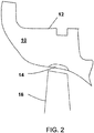
FIG. 2 illustrates an expanded view of a section ofFIG. 1 showing a repaired region of an exemplary aspect; -
FIG. 3 illustrates a sectional view of a repaired region that includes one or more butter layers and a fill layer, according to an exemplary aspect; -
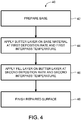
FIG. 4 illustrates a flowchart for a method for repairing a casing component that forms part of a flow path in a steam or gas turbine. - Exemplary embodiments of the present disclosure are now described with references to the drawings, wherein like reference numerals are used to refer to like elements throughout. In the following description, for purposes of explanation, numerous specific details are set forth to provide a thorough understanding of the disclosure. However, the present disclosure may be practiced without these specific details and is not limited to the exemplary embodiments disclosed herein.
- The articles "a" and "an," as used herein, mean one or more when applied to any feature in embodiments of the present invention described in the specification and claims. The use of "a" and "an" does not limit the meaning to a single feature unless such a limit is specifically stated. The article "the" preceding singular or plural nouns or noun phrases denotes a particular specified feature or particular specified features and may have a singular or plural connotation depending upon the context in which it is used. The adjective "any" means one, some, or all indiscriminately of whatever quantity.
-
FIG. 1 illustrates a section of an axial flow steam turbine to which exemplary embodiments may be applied. Shown is acasing component 10, asteam flow path 22 and alast stage 20 comprising astationary vane row 16 and a downstream rotatingblade row 18. - The
casing component 10 forms a radial outer limit of the axialsteam flow path 22, thereby in part defining the axialsteam flow path 22. Thecasing component 10 may additionally provide a carrier means for carrying one or morestationary vane rows 16. Thecasing component 10 may form only a portion of the casing of the steam turbine. That is, thecasing component 10 is one component of several components. Alternatively, thecasing component 10 may define the casing of the steam turbine. - As shown in
FIG. 1 , contained within the axialsteam flow path 22 arestationary vane rows 16 that are each followed downstream, that is an axial direction corresponding to the nominal flow direction or working fluid through theflow path 22, by rotatingblade rows 18. Thelast vane row 16 /blade row 18 combination contained within theflow path 22 defines thelast stage 20 of the turbine. - In an exemplary embodiment shown in
FIG. 2 , thecasing component 10 comprises abase 12 made of nodular cast iron (or ductile iron) and a repairedregion 14 that is located thebase 12 in a region exposed to thesteam flow path 22. The repairedregion 14 consists of a butter layer underlying a filler or fill layer. In an exemplary embodiment the repairedregion 14 is located in a region radially between the rotatingblade row 18 and thebase 12, wherein the radial direction is defined at the direction perpendicular to the rotational axis of the rotatingblade row 18. However, the repairedregion 14 may be located anywhere in or oncasing 10. -
FIG. 3 illustrates a sectional view of a repairedregion 14 that includes one or more butter layers 32 and afill layer 34, according to an aspect of the present disclosure. The substrate orbase 12 is comprised of nodular cast iron, which may also be referred to as ductile iron, ductile cast iron, spheroidal graphite iron, or spheroidal graphite cast iron. In ductile or nodule cast irons, graphite is in the form of spheres or nodules rather than flakes as in grey iron. In grey iron, sharp graphite flakes create stress concentration points within the metal matrix. In contrast, the rounded or spherical nodules in nodular cast iron inhibit the creation of cracks, providing enhanced ductility and superior mechanical properties. Prior to repair,region 14 may take the form of a cavity or recess, and this recess may be further excavated to provide a stable base on which to build the repair. The substrate or component may then be subjected to an optional pre-heating step, where the substrate is heated to a maximum of 204°C (400°F). This optional heating step is to facilitate the removal of undesired moisture levels. - After a satisfactory base shape is obtained two or more butter or buttering layers 32 are applied to
base 12. Each butter layer 32 may be comprised of nickel, a nickel alloy, a nickel iron alloy or a nickel iron manganese alloy. The butter layers 32 are relatively soft and do not form a brittle microstructure due to the large carbon pickup from thecast iron base 14. The butter layers 32 are preferably applied with low heat input, an interpass temperature less than 204°C (400°F) and low to no preheat. Interpass temperature is the temperature of the weld site at which subsequent weld runs are deposited, and a specific maximum interpass temperature is selected to control weld metal microstructural development and to minimize the risk of solidification or liquation cracking for austenitic nickel and nickel alloys. A welder must wait for the weld site to cool before making another pass, if the local temperature is above the desired interpass temperature. - A
fill layer 34 is applied on the butter layers 32. Thefill layer 34 may be comprised of 1 or more layers of low carbon steel. A low carbon steel material or welding electrode is one in which the carbon content does not exceed about 0.25% and the manganese content does not exceed about 1.65%. The carbon steel material has a similar mean coefficient of thermal expansion as the nodular cast iron ensuring that the welded region will expand and contract at the approximately same rate as base material during thermal cycles of the casing. Thefill layer 34 may be applied in one or multiple passes until a desired profile is obtained. An advantage to using thefill layer 34 is that it may deposited with a higher rate than the butter layers 32 and with higher interpass temperature, up to 400°C (750°F). - The butter layers 32 may be deposited by using a welding electrode or welding wire. One example of a material composition (by weight) for a welding/buttering electrode is iron (Fe) balance, nickel (Ni) about 56.8%, carbon (C) about 1.18%, silicon (Si) about 0.49% and manganese (Mn) about 0.49%. Mechanical properties of a resulting weld metal are a tensile strength of about 480 N/mm2 or 70 ksi, elongation of about 18% and a hardness of about 170 to 190 HV or 85-90 HRB. Additional examples of welding/buttering electrode material compositions are: Ni balance, Fe 0.80% to 5.3%, C 0.43% to 1.2%, manganese 0.25% to 2.5%, Si 0.32% to 0.70%. Furthermore, a nickel or nickel alloy welding/buttering electrode may also be employed in specific applications for the butter layers 32. A suitable Ni alloy has a composition of at least 85% Ni, a Ni-Fe alloy has 45% - 75% Ni with the balance Fe, and a Ni-Fe-Mn alloy has a minimum of 35% Ni, 10% to 15% Mn, and the balance Fe. The nickel alloys may have trace or small amounts of C, Si, Mn, Cu, Al and up to 3% strong carbide forming elements.
-
FIG. 4 illustrates a flowchart for amethod 40 for repairing a casing component that forms part of a flow path in a turbine. The turbine may be a gas turbine or a steam turbine. The method includes a preparingstep 42 that prepares the base material. Thebase material 10 is ductile cast iron or nodular cast iron. The preparingstep 42 may include identifying a region needing to be repaired or serviced, excavating this region and cleaning the region. Excavating may entail removing loose base material or profiling the shape of the region to a desired shape for subsequent repair/service. After the base material is prepared, an applyingstep 44 applies one or more butter layers 32 to thebase material 10. The butter layer(s) 32 are applied on thebase material 10 with a first preheat temperature and a first interpass temperature. The first preheat temperature may be from about room or ambient temperature up to 204°C (400°F). The interpass temperature ranges from ambient to 204°C (400°F). - A second applying
step 46 applies one or more fill layers 34 on the butter layer 32. Thefill layer 34 is applied with a second interpass temperature that ranges between ambient to 400°C (750°F). The first heat input level may be lower than the second heat input level. Thefill layer 34 may also be applied at a second deposition rate which is higher than the first deposition rate. A finishingstep 48 may be used to machine or polish the surface of the repaired area to a desired shape profile or surface roughness. - When an element or layer is referred to as being "on", "engaged to", "connected to" or "coupled to" another element or layer, it may be directly on, engaged, connected or coupled to the other element or layer, or intervening elements or layers may be present. In contrast, when an element is referred to as being "directly on," "directly engaged to", "directly connected to" or "directly coupled to" another element or layer, there may be no intervening elements or layers present. Other words used to describe the relationship between elements should be interpreted in a like fashion (e.g., "between" versus "directly between," "adjacent" versus "directly adjacent," etc.). As used herein, the term "and/or" includes any and all combinations of one or more of the associated listed items.
- This written description uses examples to disclose the invention, including the best mode, and also to enable any person skilled in the art to practice the invention, including making and using any devices or systems and performing any incorporated methods. The patentable scope of the invention is defined by the claims, and may include other examples that occur to those skilled in the art. Such other examples are intended to be within the scope of the claims if they have structural elements that do not differ from the literal language of the claims, or if they include equivalent structural elements with insubstantial differences from the literal languages of the claims.
Claims (11)
- A casing component (10) configured to form part of a flow path (22) in a turbine, the casing component comprising:a base (12) made of nodular cast iron; anda repaired region (14) in the base, the repaired region comprised of a butter layer (32) applied on the base and a fill layer (34) applied on the butter layer.
- The casing component of claim 1, wherein the butter layer (32) is comprised of a nickel alloy, a nickel-iron alloy or a nickel-iron-manganese alloy.
- The casing component of claim 1 or claim 2, wherein the fill layer (34) is comprised of carbon steel.
- The casing component of any preceding claim, wherein the turbine is a gas turbine or a steam turbine.
- A method (40) for repairing a casing component (10) that forms part of a flow path (22) in a turbine, the method comprising:applying (44) a butter layer (32) on a base material (12), the butter layer applied with a first interpass temperature;applying (46) a fill layer (34) on the butter layer, the fill layer applied with a second interpass temperature; andwherein the first interpass temperature is lower than the second interpass temperature.
- The method of claim 5, wherein the butter layer (32) is comprised of a nickel alloy, a nickel-iron alloy, or a nickel-iron-manganese alloy.
- The method of claim 5 or claim 6, wherein the fill layer (34) is comprised of carbon steel or low carbon steel.
- The method of any of claims 5 to 7, wherein the base material (12) is comprised of cast iron or nodular cast iron.
- The method of any of claims 5 to 8, wherein the applying the butter layer step (44) comprises applying multiple butter layers.
- The method of any of claims 5 to 9, wherein the first interpass temperature is between ambient to about 204°C (400°F).
- The method of any of claims 5 to 9, wherein the second interpass temperature is between ambient to about 400°C (750°F).
Priority Applications (7)
| Application Number | Priority Date | Filing Date | Title |
|---|---|---|---|
| EP19461528.2A EP3725457B1 (en) | 2019-04-17 | 2019-04-17 | Turbine casing component and repair method therefor |
| PL19461528.2T PL3725457T3 (en) | 2019-04-17 | 2019-04-17 | Turbine casing component and repair method therefor |
| CN202080029001.2A CN113692331A (en) | 2019-04-17 | 2020-04-13 | Turbine casing component and repair method thereof |
| US17/594,369 US11708770B2 (en) | 2019-04-17 | 2020-04-13 | Turbine casing component and repair method therefor |
| JP2021560674A JP7520878B2 (en) | 2019-04-17 | 2020-04-13 | Turbine casing component and repair method thereof |
| KR1020217034835A KR102845172B1 (en) | 2019-04-17 | 2020-04-13 | Turbine casing components and their maintenance methods |
| PCT/US2020/027893 WO2020214514A1 (en) | 2019-04-17 | 2020-04-13 | Turbine casing component and repair method therefor |
Applications Claiming Priority (1)
| Application Number | Priority Date | Filing Date | Title |
|---|---|---|---|
| EP19461528.2A EP3725457B1 (en) | 2019-04-17 | 2019-04-17 | Turbine casing component and repair method therefor |
Publications (2)
| Publication Number | Publication Date |
|---|---|
| EP3725457A1 true EP3725457A1 (en) | 2020-10-21 |
| EP3725457B1 EP3725457B1 (en) | 2024-07-03 |
Family
ID=66448493
Family Applications (1)
| Application Number | Title | Priority Date | Filing Date |
|---|---|---|---|
| EP19461528.2A Active EP3725457B1 (en) | 2019-04-17 | 2019-04-17 | Turbine casing component and repair method therefor |
Country Status (7)
| Country | Link |
|---|---|
| US (1) | US11708770B2 (en) |
| EP (1) | EP3725457B1 (en) |
| JP (1) | JP7520878B2 (en) |
| KR (1) | KR102845172B1 (en) |
| CN (1) | CN113692331A (en) |
| PL (1) | PL3725457T3 (en) |
| WO (1) | WO2020214514A1 (en) |
Cited By (1)
| Publication number | Priority date | Publication date | Assignee | Title |
|---|---|---|---|---|
| WO2022177452A1 (en) | 2021-02-22 | 2022-08-25 | General Electric Company | Dissimilar metal lifing enhancement |
Families Citing this family (2)
| Publication number | Priority date | Publication date | Assignee | Title |
|---|---|---|---|---|
| US12270306B2 (en) * | 2021-12-15 | 2025-04-08 | General Electric Company | Engine component with abradable material and treatment |
| CN114457332B (en) * | 2022-01-23 | 2023-11-24 | 南华大学 | Special iron-based alloy powder and method for repairing ductile iron castings |
Citations (7)
| Publication number | Priority date | Publication date | Assignee | Title |
|---|---|---|---|---|
| EP0296861A1 (en) * | 1987-06-22 | 1988-12-28 | Westinghouse Electric Corporation | Improvements in or relating to laminated metal structures for resisting wear at elevated temperatures |
| US4817859A (en) * | 1986-09-24 | 1989-04-04 | Bbc Brown Boveri Ag | Method of joining nodular cast iron to steel by means of fusion welding |
| EP0715922A1 (en) * | 1994-12-09 | 1996-06-12 | FERRY-CAPITAIN (Sarl) | Welding method by melting spheroidal graphite cast iron workpieces |
| JP2006021206A (en) * | 2004-07-06 | 2006-01-26 | Kansai Electric Power Co Inc:The | Cast steel product with weld repair location and weld repair method for cast steel product |
| JP2007021530A (en) * | 2005-07-15 | 2007-02-01 | Kansai Electric Power Co Inc:The | Welding repair method for cast steel products and cast steel products having weld repair parts |
| EP1844894A1 (en) * | 2006-04-12 | 2007-10-17 | Linde Aktiengesellschaft | Process of welding repair of cast materials having a defect; Workpiece made of cast material having such a repaired part; Use of a gas mixing for such process |
| EP2236236A1 (en) * | 2009-04-03 | 2010-10-06 | Siemens AG | Method for weld manufacturing a large-dimension component part made from spheroidal graphite iron using builtup materials |
Family Cites Families (13)
| Publication number | Priority date | Publication date | Assignee | Title |
|---|---|---|---|---|
| US4609577A (en) * | 1985-01-10 | 1986-09-02 | Armco Inc. | Method of producing weld overlay of austenitic stainless steel |
| US4897519A (en) * | 1988-03-14 | 1990-01-30 | Westinghouse Electric Co. | More creep resistant turbine rotor, and procedures for repear welding of low alloy ferrous turbine components |
| US5735045A (en) * | 1996-01-29 | 1998-04-07 | Gasi Engine Services Corporation | Method for refurbishing a jet engine |
| JP2003214113A (en) * | 2002-01-28 | 2003-07-30 | Toshiba Corp | Geothermal turbine |
| US20040258192A1 (en) * | 2003-06-16 | 2004-12-23 | General Electric Company | Mitigation of steam turbine stress corrosion cracking |
| KR101147719B1 (en) * | 2006-08-02 | 2012-05-24 | 가부시끼가이샤 도시바 | Erosion preventive method and member with erosion preventive section |
| DE102008000284A1 (en) * | 2007-03-02 | 2008-09-04 | Alstom Technology Ltd. | Power station steam turbine has inner housing of welded construction end forged or rolled steel blade roots |
| US8394215B2 (en) * | 2007-03-22 | 2013-03-12 | United Technologies Corporation | Dual process nickel alloy crack repair |
| EP2410137A1 (en) * | 2010-07-22 | 2012-01-25 | Siemens Aktiengesellschaft | Method for manufacturing a large-dimension component part made from spheroidal graphite iron |
| CN104039482B (en) * | 2011-12-15 | 2016-01-20 | 维斯塔斯风力系统集团公司 | Repair the method for defect in cast iron part and the method being connected cast iron part |
| US20160175991A1 (en) * | 2014-12-19 | 2016-06-23 | General Electric Company | Weld filler for superalloys |
| DE102015219512A1 (en) * | 2015-10-08 | 2017-04-13 | MTU Aero Engines AG | Repair of worn component surfaces |
| EP3208029B1 (en) * | 2016-02-17 | 2021-01-27 | General Electric Technology GmbH | Steam turbine inner casing component and repair method therefor |
-
2019
- 2019-04-17 EP EP19461528.2A patent/EP3725457B1/en active Active
- 2019-04-17 PL PL19461528.2T patent/PL3725457T3/en unknown
-
2020
- 2020-04-13 CN CN202080029001.2A patent/CN113692331A/en active Pending
- 2020-04-13 WO PCT/US2020/027893 patent/WO2020214514A1/en not_active Ceased
- 2020-04-13 JP JP2021560674A patent/JP7520878B2/en active Active
- 2020-04-13 KR KR1020217034835A patent/KR102845172B1/en active Active
- 2020-04-13 US US17/594,369 patent/US11708770B2/en active Active
Patent Citations (7)
| Publication number | Priority date | Publication date | Assignee | Title |
|---|---|---|---|---|
| US4817859A (en) * | 1986-09-24 | 1989-04-04 | Bbc Brown Boveri Ag | Method of joining nodular cast iron to steel by means of fusion welding |
| EP0296861A1 (en) * | 1987-06-22 | 1988-12-28 | Westinghouse Electric Corporation | Improvements in or relating to laminated metal structures for resisting wear at elevated temperatures |
| EP0715922A1 (en) * | 1994-12-09 | 1996-06-12 | FERRY-CAPITAIN (Sarl) | Welding method by melting spheroidal graphite cast iron workpieces |
| JP2006021206A (en) * | 2004-07-06 | 2006-01-26 | Kansai Electric Power Co Inc:The | Cast steel product with weld repair location and weld repair method for cast steel product |
| JP2007021530A (en) * | 2005-07-15 | 2007-02-01 | Kansai Electric Power Co Inc:The | Welding repair method for cast steel products and cast steel products having weld repair parts |
| EP1844894A1 (en) * | 2006-04-12 | 2007-10-17 | Linde Aktiengesellschaft | Process of welding repair of cast materials having a defect; Workpiece made of cast material having such a repaired part; Use of a gas mixing for such process |
| EP2236236A1 (en) * | 2009-04-03 | 2010-10-06 | Siemens AG | Method for weld manufacturing a large-dimension component part made from spheroidal graphite iron using builtup materials |
Cited By (1)
| Publication number | Priority date | Publication date | Assignee | Title |
|---|---|---|---|---|
| WO2022177452A1 (en) | 2021-02-22 | 2022-08-25 | General Electric Company | Dissimilar metal lifing enhancement |
Also Published As
| Publication number | Publication date |
|---|---|
| JP7520878B2 (en) | 2024-07-23 |
| US20220220862A1 (en) | 2022-07-14 |
| PL3725457T3 (en) | 2025-01-20 |
| KR20210151111A (en) | 2021-12-13 |
| WO2020214514A1 (en) | 2020-10-22 |
| US11708770B2 (en) | 2023-07-25 |
| CN113692331A (en) | 2021-11-23 |
| KR102845172B1 (en) | 2025-08-11 |
| JP2022529145A (en) | 2022-06-17 |
| EP3725457B1 (en) | 2024-07-03 |
Similar Documents
| Publication | Publication Date | Title |
|---|---|---|
| CN106563929B (en) | Repair and manufacture the method and turbine engine components of turbine engine components | |
| US8720056B2 (en) | Turbine rotor blade repair method | |
| US5351395A (en) | Process for producing turbine bucket with water droplet erosion protection | |
| US11708770B2 (en) | Turbine casing component and repair method therefor | |
| US6908288B2 (en) | Repair of advanced gas turbine blades | |
| JP7038545B2 (en) | Repairing brazed structure of difficult-to-weld superalloy parts using diffusion alloy inserts | |
| US11203064B2 (en) | Section replacement of a turbine airfoil with a metallic braze presintered preform | |
| JP2011062749A (en) | Superalloy composition and method of forming turbine engine component | |
| US20100059572A1 (en) | Weld repair process and article repaired thereby | |
| JP2022529145A5 (en) | ||
| CN102852559B (en) | Disk preform, its welding turbine rotor made and the method manufacturing them | |
| JP5535799B2 (en) | Repair method of metal parts and repaired metal parts | |
| CN108798805A (en) | Handle the method for turbine baffle and processed turbine baffle | |
| US20220145765A1 (en) | Tip repair of a turbine component using a composite tip boron base pre-sintered preform | |
| US11066933B2 (en) | Rotor shaft and method for producing a rotor shaft | |
| Miglietti et al. | Repair process technology development and experience for w501f row 1 hot gas path blades | |
| Miglietti et al. | Repair process technology development and experience of frame 7FA+ E, Stage 1 Turbine Buckets | |
| JP6573061B1 (en) | Welding repair method for precipitation strengthened castings | |
| JP2020037899A (en) | Method for repairing gas turbine vane and method for manufacturing high strength gas turbine vane | |
| Curtis et al. | Development and Implementation of Repair Processes for Refurbishment of W501F, Row 1 Turbine Blades | |
| EP2564978A1 (en) | Filler metal chemistry for improved weldability of super alloys | |
| RU2742963C1 (en) | Method of hard to weld materials production | |
| Gowreesan et al. | Weld Repair of Steam Turbine Rotor with 12 Cr Weld to Mitigate Corrosion Issues | |
| Miglietti et al. | Liquid Phase Diffusion Bond Repair of Westinghouse 501F, Row 3 Vanes | |
| Anton et al. | Repair of advanced gas turbine blades |
Legal Events
| Date | Code | Title | Description |
|---|---|---|---|
| PUAI | Public reference made under article 153(3) epc to a published international application that has entered the european phase |
Free format text: ORIGINAL CODE: 0009012 |
|
| STAA | Information on the status of an ep patent application or granted ep patent |
Free format text: STATUS: THE APPLICATION HAS BEEN PUBLISHED |
|
| AK | Designated contracting states |
Kind code of ref document: A1 Designated state(s): AL AT BE BG CH CY CZ DE DK EE ES FI FR GB GR HR HU IE IS IT LI LT LU LV MC MK MT NL NO PL PT RO RS SE SI SK SM TR |
|
| AX | Request for extension of the european patent |
Extension state: BA ME |
|
| STAA | Information on the status of an ep patent application or granted ep patent |
Free format text: STATUS: REQUEST FOR EXAMINATION WAS MADE |
|
| 17P | Request for examination filed |
Effective date: 20210409 |
|
| RBV | Designated contracting states (corrected) |
Designated state(s): AL AT BE BG CH CY CZ DE DK EE ES FI FR GB GR HR HU IE IS IT LI LT LU LV MC MK MT NL NO PL PT RO RS SE SI SK SM TR |
|
| RAP1 | Party data changed (applicant data changed or rights of an application transferred) |
Owner name: GENERAL ELECTRIC TECHNOLOGY GMBH |
|
| RIC1 | Information provided on ipc code assigned before grant |
Ipc: C22C 19/03 20060101ALN20231218BHEP Ipc: C22C 37/04 20060101ALI20231218BHEP Ipc: B32B 15/01 20060101ALI20231218BHEP Ipc: F01D 25/24 20060101ALI20231218BHEP Ipc: B23K 35/30 20060101ALI20231218BHEP Ipc: F01D 5/00 20060101ALI20231218BHEP Ipc: B23P 6/00 20060101AFI20231218BHEP |
|
| GRAP | Despatch of communication of intention to grant a patent |
Free format text: ORIGINAL CODE: EPIDOSNIGR1 |
|
| STAA | Information on the status of an ep patent application or granted ep patent |
Free format text: STATUS: GRANT OF PATENT IS INTENDED |
|
| RIC1 | Information provided on ipc code assigned before grant |
Ipc: C22C 19/03 20060101ALN20240114BHEP Ipc: C22C 37/04 20060101ALI20240114BHEP Ipc: B32B 15/01 20060101ALI20240114BHEP Ipc: F01D 25/24 20060101ALI20240114BHEP Ipc: B23K 35/30 20060101ALI20240114BHEP Ipc: F01D 5/00 20060101ALI20240114BHEP Ipc: B23P 6/00 20060101AFI20240114BHEP |
|
| RIC1 | Information provided on ipc code assigned before grant |
Ipc: C22C 19/03 20060101ALN20240125BHEP Ipc: C22C 37/04 20060101ALI20240125BHEP Ipc: B32B 15/01 20060101ALI20240125BHEP Ipc: F01D 25/24 20060101ALI20240125BHEP Ipc: B23K 35/30 20060101ALI20240125BHEP Ipc: F01D 5/00 20060101ALI20240125BHEP Ipc: B23P 6/00 20060101AFI20240125BHEP |
|
| INTG | Intention to grant announced |
Effective date: 20240205 |
|
| GRAS | Grant fee paid |
Free format text: ORIGINAL CODE: EPIDOSNIGR3 |
|
| GRAA | (expected) grant |
Free format text: ORIGINAL CODE: 0009210 |
|
| STAA | Information on the status of an ep patent application or granted ep patent |
Free format text: STATUS: THE PATENT HAS BEEN GRANTED |
|
| AK | Designated contracting states |
Kind code of ref document: B1 Designated state(s): AL AT BE BG CH CY CZ DE DK EE ES FI FR GB GR HR HU IE IS IT LI LT LU LV MC MK MT NL NO PL PT RO RS SE SI SK SM TR |
|
| REG | Reference to a national code |
Ref country code: CH Ref legal event code: EP |
|
| REG | Reference to a national code |
Ref country code: DE Ref legal event code: R096 Ref document number: 602019054528 Country of ref document: DE |
|
| REG | Reference to a national code |
Ref country code: LT Ref legal event code: MG9D |
|
| REG | Reference to a national code |
Ref country code: NL Ref legal event code: MP Effective date: 20240703 |
|
| PG25 | Lapsed in a contracting state [announced via postgrant information from national office to epo] |
Ref country code: PT Free format text: LAPSE BECAUSE OF FAILURE TO SUBMIT A TRANSLATION OF THE DESCRIPTION OR TO PAY THE FEE WITHIN THE PRESCRIBED TIME-LIMIT Effective date: 20241104 |
|
| REG | Reference to a national code |
Ref country code: AT Ref legal event code: MK05 Ref document number: 1699350 Country of ref document: AT Kind code of ref document: T Effective date: 20240703 |
|
| PG25 | Lapsed in a contracting state [announced via postgrant information from national office to epo] |
Ref country code: NL Free format text: LAPSE BECAUSE OF FAILURE TO SUBMIT A TRANSLATION OF THE DESCRIPTION OR TO PAY THE FEE WITHIN THE PRESCRIBED TIME-LIMIT Effective date: 20240703 |
|
| PG25 | Lapsed in a contracting state [announced via postgrant information from national office to epo] |
Ref country code: PT Free format text: LAPSE BECAUSE OF FAILURE TO SUBMIT A TRANSLATION OF THE DESCRIPTION OR TO PAY THE FEE WITHIN THE PRESCRIBED TIME-LIMIT Effective date: 20241104 Ref country code: NL Free format text: LAPSE BECAUSE OF FAILURE TO SUBMIT A TRANSLATION OF THE DESCRIPTION OR TO PAY THE FEE WITHIN THE PRESCRIBED TIME-LIMIT Effective date: 20240703 |
|
| PG25 | Lapsed in a contracting state [announced via postgrant information from national office to epo] |
Ref country code: NO Free format text: LAPSE BECAUSE OF FAILURE TO SUBMIT A TRANSLATION OF THE DESCRIPTION OR TO PAY THE FEE WITHIN THE PRESCRIBED TIME-LIMIT Effective date: 20241003 |
|
| PG25 | Lapsed in a contracting state [announced via postgrant information from national office to epo] |
Ref country code: FI Free format text: LAPSE BECAUSE OF FAILURE TO SUBMIT A TRANSLATION OF THE DESCRIPTION OR TO PAY THE FEE WITHIN THE PRESCRIBED TIME-LIMIT Effective date: 20240703 Ref country code: GR Free format text: LAPSE BECAUSE OF FAILURE TO SUBMIT A TRANSLATION OF THE DESCRIPTION OR TO PAY THE FEE WITHIN THE PRESCRIBED TIME-LIMIT Effective date: 20241004 |
|
| PG25 | Lapsed in a contracting state [announced via postgrant information from national office to epo] |
Ref country code: BG Free format text: LAPSE BECAUSE OF FAILURE TO SUBMIT A TRANSLATION OF THE DESCRIPTION OR TO PAY THE FEE WITHIN THE PRESCRIBED TIME-LIMIT Effective date: 20240703 |
|
| PG25 | Lapsed in a contracting state [announced via postgrant information from national office to epo] |
Ref country code: LV Free format text: LAPSE BECAUSE OF FAILURE TO SUBMIT A TRANSLATION OF THE DESCRIPTION OR TO PAY THE FEE WITHIN THE PRESCRIBED TIME-LIMIT Effective date: 20240703 |
|
| PG25 | Lapsed in a contracting state [announced via postgrant information from national office to epo] |
Ref country code: AT Free format text: LAPSE BECAUSE OF FAILURE TO SUBMIT A TRANSLATION OF THE DESCRIPTION OR TO PAY THE FEE WITHIN THE PRESCRIBED TIME-LIMIT Effective date: 20240703 Ref country code: IS Free format text: LAPSE BECAUSE OF FAILURE TO SUBMIT A TRANSLATION OF THE DESCRIPTION OR TO PAY THE FEE WITHIN THE PRESCRIBED TIME-LIMIT Effective date: 20241103 |
|
| PG25 | Lapsed in a contracting state [announced via postgrant information from national office to epo] |
Ref country code: CZ Free format text: LAPSE BECAUSE OF FAILURE TO SUBMIT A TRANSLATION OF THE DESCRIPTION OR TO PAY THE FEE WITHIN THE PRESCRIBED TIME-LIMIT Effective date: 20240703 Ref country code: HR Free format text: LAPSE BECAUSE OF FAILURE TO SUBMIT A TRANSLATION OF THE DESCRIPTION OR TO PAY THE FEE WITHIN THE PRESCRIBED TIME-LIMIT Effective date: 20240703 |
|
| PG25 | Lapsed in a contracting state [announced via postgrant information from national office to epo] |
Ref country code: ES Free format text: LAPSE BECAUSE OF FAILURE TO SUBMIT A TRANSLATION OF THE DESCRIPTION OR TO PAY THE FEE WITHIN THE PRESCRIBED TIME-LIMIT Effective date: 20240703 Ref country code: RS Free format text: LAPSE BECAUSE OF FAILURE TO SUBMIT A TRANSLATION OF THE DESCRIPTION OR TO PAY THE FEE WITHIN THE PRESCRIBED TIME-LIMIT Effective date: 20241003 |
|
| PG25 | Lapsed in a contracting state [announced via postgrant information from national office to epo] |
Ref country code: RS Free format text: LAPSE BECAUSE OF FAILURE TO SUBMIT A TRANSLATION OF THE DESCRIPTION OR TO PAY THE FEE WITHIN THE PRESCRIBED TIME-LIMIT Effective date: 20241003 Ref country code: NO Free format text: LAPSE BECAUSE OF FAILURE TO SUBMIT A TRANSLATION OF THE DESCRIPTION OR TO PAY THE FEE WITHIN THE PRESCRIBED TIME-LIMIT Effective date: 20241003 Ref country code: LV Free format text: LAPSE BECAUSE OF FAILURE TO SUBMIT A TRANSLATION OF THE DESCRIPTION OR TO PAY THE FEE WITHIN THE PRESCRIBED TIME-LIMIT Effective date: 20240703 Ref country code: IS Free format text: LAPSE BECAUSE OF FAILURE TO SUBMIT A TRANSLATION OF THE DESCRIPTION OR TO PAY THE FEE WITHIN THE PRESCRIBED TIME-LIMIT Effective date: 20241103 Ref country code: HR Free format text: LAPSE BECAUSE OF FAILURE TO SUBMIT A TRANSLATION OF THE DESCRIPTION OR TO PAY THE FEE WITHIN THE PRESCRIBED TIME-LIMIT Effective date: 20240703 Ref country code: GR Free format text: LAPSE BECAUSE OF FAILURE TO SUBMIT A TRANSLATION OF THE DESCRIPTION OR TO PAY THE FEE WITHIN THE PRESCRIBED TIME-LIMIT Effective date: 20241004 Ref country code: FI Free format text: LAPSE BECAUSE OF FAILURE TO SUBMIT A TRANSLATION OF THE DESCRIPTION OR TO PAY THE FEE WITHIN THE PRESCRIBED TIME-LIMIT Effective date: 20240703 Ref country code: ES Free format text: LAPSE BECAUSE OF FAILURE TO SUBMIT A TRANSLATION OF THE DESCRIPTION OR TO PAY THE FEE WITHIN THE PRESCRIBED TIME-LIMIT Effective date: 20240703 Ref country code: CZ Free format text: LAPSE BECAUSE OF FAILURE TO SUBMIT A TRANSLATION OF THE DESCRIPTION OR TO PAY THE FEE WITHIN THE PRESCRIBED TIME-LIMIT Effective date: 20240703 Ref country code: BG Free format text: LAPSE BECAUSE OF FAILURE TO SUBMIT A TRANSLATION OF THE DESCRIPTION OR TO PAY THE FEE WITHIN THE PRESCRIBED TIME-LIMIT Effective date: 20240703 Ref country code: AT Free format text: LAPSE BECAUSE OF FAILURE TO SUBMIT A TRANSLATION OF THE DESCRIPTION OR TO PAY THE FEE WITHIN THE PRESCRIBED TIME-LIMIT Effective date: 20240703 |
|
| REG | Reference to a national code |
Ref country code: DE Ref legal event code: R097 Ref document number: 602019054528 Country of ref document: DE |
|
| PG25 | Lapsed in a contracting state [announced via postgrant information from national office to epo] |
Ref country code: SM Free format text: LAPSE BECAUSE OF FAILURE TO SUBMIT A TRANSLATION OF THE DESCRIPTION OR TO PAY THE FEE WITHIN THE PRESCRIBED TIME-LIMIT Effective date: 20240703 Ref country code: DK Free format text: LAPSE BECAUSE OF FAILURE TO SUBMIT A TRANSLATION OF THE DESCRIPTION OR TO PAY THE FEE WITHIN THE PRESCRIBED TIME-LIMIT Effective date: 20240703 Ref country code: RO Free format text: LAPSE BECAUSE OF FAILURE TO SUBMIT A TRANSLATION OF THE DESCRIPTION OR TO PAY THE FEE WITHIN THE PRESCRIBED TIME-LIMIT Effective date: 20240703 |
|
| PG25 | Lapsed in a contracting state [announced via postgrant information from national office to epo] |
Ref country code: EE Free format text: LAPSE BECAUSE OF FAILURE TO SUBMIT A TRANSLATION OF THE DESCRIPTION OR TO PAY THE FEE WITHIN THE PRESCRIBED TIME-LIMIT Effective date: 20240703 |
|
| PG25 | Lapsed in a contracting state [announced via postgrant information from national office to epo] |
Ref country code: SK Free format text: LAPSE BECAUSE OF FAILURE TO SUBMIT A TRANSLATION OF THE DESCRIPTION OR TO PAY THE FEE WITHIN THE PRESCRIBED TIME-LIMIT Effective date: 20240703 |
|
| PLBE | No opposition filed within time limit |
Free format text: ORIGINAL CODE: 0009261 |
|
| STAA | Information on the status of an ep patent application or granted ep patent |
Free format text: STATUS: NO OPPOSITION FILED WITHIN TIME LIMIT |
|
| 26N | No opposition filed |
Effective date: 20250404 |
|
| PGFP | Annual fee paid to national office [announced via postgrant information from national office to epo] |
Ref country code: DE Payment date: 20250319 Year of fee payment: 7 |
|
| PG25 | Lapsed in a contracting state [announced via postgrant information from national office to epo] |
Ref country code: SE Free format text: LAPSE BECAUSE OF FAILURE TO SUBMIT A TRANSLATION OF THE DESCRIPTION OR TO PAY THE FEE WITHIN THE PRESCRIBED TIME-LIMIT Effective date: 20240703 |
|
| REG | Reference to a national code |
Ref country code: CH Ref legal event code: H13 Free format text: ST27 STATUS EVENT CODE: U-0-0-H10-H13 (AS PROVIDED BY THE NATIONAL OFFICE) Effective date: 20251125 |
|
| PG25 | Lapsed in a contracting state [announced via postgrant information from national office to epo] |
Ref country code: LU Free format text: LAPSE BECAUSE OF NON-PAYMENT OF DUE FEES Effective date: 20250417 |
|
| PG25 | Lapsed in a contracting state [announced via postgrant information from national office to epo] |
Ref country code: MC Free format text: LAPSE BECAUSE OF FAILURE TO SUBMIT A TRANSLATION OF THE DESCRIPTION OR TO PAY THE FEE WITHIN THE PRESCRIBED TIME-LIMIT Effective date: 20240703 |
|
| REG | Reference to a national code |
Ref country code: BE Ref legal event code: MM Effective date: 20250430 |
|
| PG25 | Lapsed in a contracting state [announced via postgrant information from national office to epo] |
Ref country code: FR Free format text: LAPSE BECAUSE OF NON-PAYMENT OF DUE FEES Effective date: 20250430 |
|
| PG25 | Lapsed in a contracting state [announced via postgrant information from national office to epo] |
Ref country code: BE Free format text: LAPSE BECAUSE OF NON-PAYMENT OF DUE FEES Effective date: 20250430 |
|
| PG25 | Lapsed in a contracting state [announced via postgrant information from national office to epo] |
Ref country code: CH Free format text: LAPSE BECAUSE OF NON-PAYMENT OF DUE FEES Effective date: 20250430 |
|
| PGFP | Annual fee paid to national office [announced via postgrant information from national office to epo] |
Ref country code: GB Payment date: 20260319 Year of fee payment: 8 |
|
| PG25 | Lapsed in a contracting state [announced via postgrant information from national office to epo] |
Ref country code: IE Free format text: LAPSE BECAUSE OF NON-PAYMENT OF DUE FEES Effective date: 20250417 |
|
| PGFP | Annual fee paid to national office [announced via postgrant information from national office to epo] |
Ref country code: IT Payment date: 20260319 Year of fee payment: 8 |
|
| PGFP | Annual fee paid to national office [announced via postgrant information from national office to epo] |
Ref country code: PL Payment date: 20260319 Year of fee payment: 8 |