EP3725278A1 - Apparatus for manufacturing absorbent core of disposable wearing article and exchange method for exchanging part of said apparatus - Google Patents
Apparatus for manufacturing absorbent core of disposable wearing article and exchange method for exchanging part of said apparatus Download PDFInfo
- Publication number
- EP3725278A1 EP3725278A1 EP18888016.5A EP18888016A EP3725278A1 EP 3725278 A1 EP3725278 A1 EP 3725278A1 EP 18888016 A EP18888016 A EP 18888016A EP 3725278 A1 EP3725278 A1 EP 3725278A1
- Authority
- EP
- European Patent Office
- Prior art keywords
- fiber
- stacking
- rotation shaft
- wheel
- drum
- Prior art date
- Legal status (The legal status is an assumption and is not a legal conclusion. Google has not performed a legal analysis and makes no representation as to the accuracy of the status listed.)
- Pending
Links
Images




Classifications
-
- A—HUMAN NECESSITIES
- A61—MEDICAL OR VETERINARY SCIENCE; HYGIENE
- A61F—FILTERS IMPLANTABLE INTO BLOOD VESSELS; PROSTHESES; DEVICES PROVIDING PATENCY TO, OR PREVENTING COLLAPSING OF, TUBULAR STRUCTURES OF THE BODY, e.g. STENTS; ORTHOPAEDIC, NURSING OR CONTRACEPTIVE DEVICES; FOMENTATION; TREATMENT OR PROTECTION OF EYES OR EARS; BANDAGES, DRESSINGS OR ABSORBENT PADS; FIRST-AID KITS
- A61F13/00—Bandages or dressings; Absorbent pads
- A61F13/15—Absorbent pads, e.g. sanitary towels, swabs or tampons for external or internal application to the body; Supporting or fastening means therefor; Tampon applicators
- A61F13/15577—Apparatus or processes for manufacturing
- A61F13/15617—Making absorbent pads from fibres or pulverulent material with or without treatment of the fibres
- A61F13/15642—Making absorbent pads from fibres or pulverulent material with or without treatment of the fibres by depositing continuous layers or pads of fibrous material on single sheets or webs
-
- A—HUMAN NECESSITIES
- A61—MEDICAL OR VETERINARY SCIENCE; HYGIENE
- A61F—FILTERS IMPLANTABLE INTO BLOOD VESSELS; PROSTHESES; DEVICES PROVIDING PATENCY TO, OR PREVENTING COLLAPSING OF, TUBULAR STRUCTURES OF THE BODY, e.g. STENTS; ORTHOPAEDIC, NURSING OR CONTRACEPTIVE DEVICES; FOMENTATION; TREATMENT OR PROTECTION OF EYES OR EARS; BANDAGES, DRESSINGS OR ABSORBENT PADS; FIRST-AID KITS
- A61F13/00—Bandages or dressings; Absorbent pads
- A61F13/15—Absorbent pads, e.g. sanitary towels, swabs or tampons for external or internal application to the body; Supporting or fastening means therefor; Tampon applicators
- A61F13/15577—Apparatus or processes for manufacturing
- A61F13/15764—Transferring, feeding or handling devices; Drives
-
- D—TEXTILES; PAPER
- D04—BRAIDING; LACE-MAKING; KNITTING; TRIMMINGS; NON-WOVEN FABRICS
- D04H—MAKING TEXTILE FABRICS, e.g. FROM FIBRES OR FILAMENTARY MATERIAL; FABRICS MADE BY SUCH PROCESSES OR APPARATUS, e.g. FELTS, NON-WOVEN FABRICS; COTTON-WOOL; WADDING ; NON-WOVEN FABRICS FROM STAPLE FIBRES, FILAMENTS OR YARNS, BONDED WITH AT LEAST ONE WEB-LIKE MATERIAL DURING THEIR CONSOLIDATION
- D04H1/00—Non-woven fabrics formed wholly or mainly of staple fibres or like relatively short fibres
- D04H1/40—Non-woven fabrics formed wholly or mainly of staple fibres or like relatively short fibres from fleeces or layers composed of fibres without existing or potential cohesive properties
- D04H1/44—Non-woven fabrics formed wholly or mainly of staple fibres or like relatively short fibres from fleeces or layers composed of fibres without existing or potential cohesive properties the fleeces or layers being consolidated by mechanical means, e.g. by rolling
-
- A—HUMAN NECESSITIES
- A61—MEDICAL OR VETERINARY SCIENCE; HYGIENE
- A61F—FILTERS IMPLANTABLE INTO BLOOD VESSELS; PROSTHESES; DEVICES PROVIDING PATENCY TO, OR PREVENTING COLLAPSING OF, TUBULAR STRUCTURES OF THE BODY, e.g. STENTS; ORTHOPAEDIC, NURSING OR CONTRACEPTIVE DEVICES; FOMENTATION; TREATMENT OR PROTECTION OF EYES OR EARS; BANDAGES, DRESSINGS OR ABSORBENT PADS; FIRST-AID KITS
- A61F13/00—Bandages or dressings; Absorbent pads
- A61F13/15—Absorbent pads, e.g. sanitary towels, swabs or tampons for external or internal application to the body; Supporting or fastening means therefor; Tampon applicators
- A61F13/15577—Apparatus or processes for manufacturing
- A61F13/15617—Making absorbent pads from fibres or pulverulent material with or without treatment of the fibres
- A61F13/15658—Forming continuous, e.g. composite, fibrous webs, e.g. involving the application of pulverulent material on parts thereof
-
- D—TEXTILES; PAPER
- D10—INDEXING SCHEME ASSOCIATED WITH SUBLASSES OF SECTION D, RELATING TO TEXTILES
- D10B—INDEXING SCHEME ASSOCIATED WITH SUBLASSES OF SECTION D, RELATING TO TEXTILES
- D10B2509/00—Medical; Hygiene
- D10B2509/02—Bandages, dressings or absorbent pads
- D10B2509/026—Absorbent pads; Tampons; Laundry; Towels
Definitions
- the present invention relates to an apparatus for manufacturing an absorbent core of a disposable worn article and a method for replacing a part of the apparatus.
- an absorbent body is typically formed by allowing a crushed fiber to be adsorbed on a fiber-stacking depression formed on the outer circumference of a fiber-stacking drum.
- the fiber-stacking depression of the drum is formed in a predetermined pattern on the outer circumferential surface of a cylindrical fiber-stacking ring, there is a need to change the pattern in accordance with the size of the worn article, for example.
- the pattern is formed of segments such as a large number of templates and mesh members arranged along the circumferential direction of the drum.
- a hood for drawing the fiber onto the drum and a conveyer for introducing a carrier web onto the drum are opposing the outer circumferential surface of the drum.
- the fiber-stacking drum is slidable in the axial direction of the rotation shaft so that the drum can be moved away from the hood and the conveyer. This allows for replacement of segments of the drum such as a large number of templates and mesh members, while preventing interference by the hood and the conveyer.
- the apparatus of the present invention is an apparatus for manufacturing an absorbent core of a disposable worn article, including:
- the method of the present invention is a replacement method for replacing the wheel 21 and the fiber-stacking ring 22 of the fiber-stacking drum 2 of the manufacturing apparatus, the replacement method including the steps of:
- the fiber-stacking ring 22 and the wheel 21 can be replaced without disassembling the fiber-stacking ring 22 into segments. Therefore, the replacement operation can be done in a short amount of time. This, as a result, improves the facility utilization rate.
- the fiber-stacking drum 2 further includes a cylindrical bearing cylinder 24 for rotatably supporting the rotation shaft 20; and the fiber-stacking drum 2 including the bearing cylinder 24 is supported by the fixed frame 5 so as to be slidable relative to the fixed frame 5 in the axial direction S.
- an output section M1 of a motor M for rotating the rotation shaft 20 is linked to the other end of the rotation shaft 20; and the motor M, together with the bearing cylinder 24, is supported by the fixed frame 5 so as to be slidable relative to the fixed frame 5 in the axial direction S.
- the replacement can be done while the motor M remains linked to the rotation shaft 20.
- the motor M remains linked to the rotation shaft 20.
- the manufacturing apparatus further includes:
- the manufacturing apparatus further includes an actuator 7 for sliding the slider 25 along the linear guide 41.
- An absorbent core to be manufactured by the present manufacturing apparatus is used as the core of incontinence pads as well as disposable pants and diapers, for example, and has an hourglass-like shape, for example.
- the present manufacturing apparatus includes a dispenser 1, a fiber-stacking drum 2, a suction chamber 6, a guide roll 8 and a conveyer 9.
- the dispenser 1 includes a dome-shaped case 10 and a defibrator (a defibration machine) 11.
- the defibrator 11 defibrates (crushes) a pulp dispensed from upstream into a fibrous material to produce a fluff pulp (fiber).
- the fluff pulp fills up the case 10, and with the suction chamber 6 of the fiber-stacking drum 2 set at a negative pressure, the fluff pulp is stacked onto the fiber-stacking ring 22 of the fiber-stacking drum 2.
- Such defibration and fiber-stacking are techniques well known in the art, and are disclosed in JP2009-112438A , for example.
- a granular material of a polymer compound having a high absorption capacity called "SAP" may be added as a material of the absorbent core.
- the fiber-stacking ring 22 of FIG. 4A is generally cylindrical and includes a plurality of, or a large number of, segments 3 arranged along the circumferential direction R of FIG. 1 .
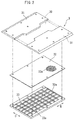
- FIG. 2 shows components of one segment 3 disassembled and arranged in a flat layout.
- Each segment 3 includes a template 31, a mesh member 32 and a lattice member 33, etc.
- a large number of, or countless, through holes 32a are formed in the mesh member 32 by performing an etching process well known in the art on a thin metal plate.
- the through holes 32a are sized so that they allow air therethrough but can receive the fiber and SAP.
- a pair of templates 31 are provided and arranged on the outer circumferential surface side of the mesh member 32, forming a fiber-stacking depression 30.
- the pair of templates 31 and 31 are spaced apart from each other in the width direction D, wherein the space therebetween forms the fiber-stacking depression 30.
- the fiber stacked in the fiber-stacking depression 30 becomes an absorbent core of an individual worn article.
- the fiber-stacking drum 2 of FIG. 1 while continuously rotating in the circumferential direction R, sucks the fiber dispensed from the dispenser 1 toward the suction chamber 6 on the inner side from an outer circumferential surface 2f ( FIG. 4A ) of the fiber-stacking ring 22, thereby continuously stacking the fiber onto the outer circumferential surface 2f of a predetermined fiber-stacking depression 30 of FIG. 4B . That is, the fiber is stacked on the outer circumferential surface 2f of the cylindrical fiber-stacking ring 22 defining the fiber-stacking depression 30.
- the lattice member 33 of FIG. 2 is formed of frames 33a extending in the width direction D and the circumferential direction R so as not to inhibit suction of the fiber.
- the lattice member 33 is in contact with the mesh member 32 and supports the inner circumferential surface of the mesh member 32, which is vulnerable to an external force.
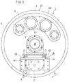
- the suction chamber 6 is arranged over a predetermined section of the fiber-stacking drum 2 in the circumferential direction R, and is connected to a negative pressure source (not shown) via a plurality of ducts 61 so that the inside of the chamber is at a negative pressure.
- the suction chamber 6 is arranged close to the inner circumference side of the fiber-stacking ring 22 of the fiber-stacking drum 2. That is, the suction chamber 6 is fixed to the fixed frame 5, wherein the suction chamber 6 is in contact with the inner circumference of (arranged on the inner side of) the fiber-stacking ring 22 and produces a suction force exerting from the outer circumference of the fiber-stacking ring 22 toward the inner circumference of the fiber-stacking ring 22.
- this suction chamber 6 may be fixed to the fixed frame 5 via the ducts 61.
- the fixed frame 5 is a vertical place well known in the art that supports the various machine parts of the apparatus for manufacturing a disposable worn article. As will be described below, the fixed frame 5 rotatably supports the fiber-stacking drum 2.
- the fiber-stacking drum 2 includes a rotation shaft 20 that is rotated, a wheel 21 attached to the distal end (one end) of the rotation shaft 20, and the cylindrical fiber-stacking ring 22.
- the fiber-stacking ring 22 is provided on the outer circumference portion along the edge of the wheel 21 for stacking the fiber.
- the wheel 21 is removably attached to the distal end (one end) of the rotation shaft 20 via a fastener 23.
- the fastener 23 may include a plurality of bolts, which pass through the wheel 21 and are screwed into the distal end of the rotation shaft 20.
- the fiber-stacking ring 22 includes a pair of annular frame rings 29.
- a large number of segments 3 are arranged next to each other in the circumferential direction R as shown in FIG. 1 along the annular frame rings 29.
- the pair of frame rings 29, 29 are linked to each other in the axial direction S via the lattice member 33.
- the template 31, the mesh member 32 and the lattice member 33 of each segment 3 are fixed between the pair of frame rings 29, 29 in the axial direction S.
- the fiber-stacking drum 2 further includes a cylindrical bearing cylinder (a cylindrical bearing sleeve) 24 that rotatably supports the rotation shaft 20.
- An output section M1 of a servomotor M that rotates the rotation shaft 20 is linked to the proximal end (the other end) of the rotation shaft 20 via a decelerator G and a coupling J.
- the motor M is fixed to the bearing cylinder 24 via the decelerator G.
- a link portion 26 is attached to the bearing cylinder 24, and a case 28 extending in the axial direction S is attached to one end of the link portion 26.
- a portion of the rotation shaft 20 and the coupling J are accommodated inside the case 28, and the opening of the case 28 is covered (lidded) by the decelerator G. That is, the rotation shaft 20 and the coupling J are accommodated in the space that is formed by the bearing cylinder 24, the case 28 and the decelerator G, and it is therefore possible to prevent the crushed fluff pulp (fiber) from being stuck on the rotation shaft 20, etc.
- the bearing cylinder 24 is fixed to a slider 25. That is, the slider 25 is attached to the bearing cylinder 24 via the link portion 26 and a moving plate 42.
- the slider 25 is guided by a linear guide 41 in the direction parallel to the axial direction S.
- the linear guide 41 is fixed to the fixed frame 5 via a base 4. Note that the slider 25 is colored in gray in the figures.
- An actuator 7 such as an air cylinder is attached to the base 4. That is, the actuator 7 is fixed to the fixed frame 5 via the base 4. In other words, the actuator 7 is attached to a non-rotating portion of the present manufacturing apparatus.
- the actuator 7 slides the motor M, the bearing cylinder 24 and the fiber-stacking drum 2 in the axial direction S via the slider 25, the moving plate 42 and the link portion 26.
- the moving plate 42 is fixed to the distal end of a rod 71 of an air cylinder 7, and the fiber-stacking drum 2 slides between the operation position P1 of FIG. 4A and the replacement position P2 of FIG. 5 .
- the fiber-stacking drum 2 together with the motor M and the bearing cylinder 24, is supported by the fixed frame 5 so as to be slidable relative to the fixed frame 5 in the axial direction S, in which the axial line L of the rotation shaft 20 extends.
- the bearing cylinder 24, the motor M and the fiber-stacking drum 2 can easily slide in the axial direction S.
- the fiber-stacking drum 2 is set to the operation position P1 of FIG. 4A .
- a carrier web W is continuously introduced from the guide roll 8 onto the fiber-stacking drum 2 of FIG. 1 .
- the fiber dispensed from the dispenser 1 is sucked by the suction chamber 6 toward the inside from the outer circumferential surface 2f of the fiber-stacking drum 2 (the outer circumferential surface 2f of the fiber-stacking depression 30 ).
- the fiber is continuously stacked on the outer circumferential surface 2f ( FIG. 4B ) of the fiber-stacking depression 30, thereby producing a continuous core C.
- the carrier web W dispensed from the guide roll 8 is laid over the stacked continuous core C. Then, the continuous core C and the carrier web W are rolled out of the fiber-stacking drum 2 as an integral material. Then, as well known in the art, it may be severed into absorbent cores of individual worn articles on the downstream side (not shown). Instead of producing the continuous core C, individual absorbent cores may be produced by fiber-stacking on the fiber-stacking drum 2.
- the operator slides the fiber-stacking drum 2 of FIG. 4A from the operation position P1 to the replacement position P2 of FIG. 5 . That is, the wheel 21 and the fiber-stacking ring 22 are moved from the operation position P1 to the replacement position P2 of FIG. 5 by sliding the motor M, the bearing cylinder 24 and the fiber-stacking drum 2 in the first direction D1 along the axial line L by protruding the rod 71 of the air cylinder 7 of FIG. 4A . Thus, the wheel 21 and the fiber-stacking ring 22 move to a position away from the dispenser 1 ( FIG. 1 ).
- first direction D1 means the direction from the proximal end (the proximal end of the rotation shaft 20 ) to which the output section M1 of the motor M is linked toward one end (one end of the rotation shaft 20 ) to which the wheel 21 is attached.
- the operator moves another wheel (a substitute wheel) 21A and another fiber-stacking ring (a substitute fiber-stacking ring) 22A of FIG. 7 from a second platform truck 102 and attaches them to the distal end of the rotation shaft 20, in place of the wheel 21 and the fiber-stacking ring 22 of FIG. 6 having been removed.
- the segments 3 on the other fiber-stacking ring 22A may be of a different pattern from the segments of the removed fiber-stacking ring 22.
- the operator actuates the actuator 7 to slide the rotation shaft 20, to which the other wheel 21A and the other fiber-stacking ring 22A have been attached, together with the motor M and the bearing cylinder 24 of FIG. 5 , in the second direction D2, which is opposite to the first direction D1.
- the replacement of the wheel and the fiber-stacking ring may be done for a change in the shape of the absorbent core, instead of a change in size.
- a plurality of through holes may be provided in the wheel for reducing the weight thereof.
- the present invention is applicable to an apparatus for manufacturing an absorbent core of a disposable worn article.
Landscapes
- Health & Medical Sciences (AREA)
- Engineering & Computer Science (AREA)
- Animal Behavior & Ethology (AREA)
- General Health & Medical Sciences (AREA)
- Biomedical Technology (AREA)
- Heart & Thoracic Surgery (AREA)
- Vascular Medicine (AREA)
- Life Sciences & Earth Sciences (AREA)
- Manufacturing & Machinery (AREA)
- Epidemiology (AREA)
- Public Health (AREA)
- Veterinary Medicine (AREA)
- Mechanical Engineering (AREA)
- Textile Engineering (AREA)
- Absorbent Articles And Supports Therefor (AREA)
- Nonwoven Fabrics (AREA)
Abstract
Description
- The present invention relates to an apparatus for manufacturing an absorbent core of a disposable worn article and a method for replacing a part of the apparatus.
- As a method for manufacturing an absorbent core of this type, an absorbent body is typically formed by allowing a crushed fiber to be adsorbed on a fiber-stacking depression formed on the outer circumference of a fiber-stacking drum.
- While the fiber-stacking depression of the drum is formed in a predetermined pattern on the outer circumferential surface of a cylindrical fiber-stacking ring, there is a need to change the pattern in accordance with the size of the worn article, for example. The pattern is formed of segments such as a large number of templates and mesh members arranged along the circumferential direction of the drum.
- On the other hand, a hood for drawing the fiber onto the drum and a conveyer for introducing a carrier web onto the drum are opposing the outer circumferential surface of the drum.
- With the apparatus of the first patent document identified below, the fiber-stacking drum is slidable in the axial direction of the rotation shaft so that the drum can be moved away from the hood and the conveyer. This allows for replacement of segments of the drum such as a large number of templates and mesh members, while preventing interference by the hood and the conveyer.
- First Patent Document:
USP4,995,141 (front page) - With the prior art, however, there is a need to disassemble segments from the drum for replacement. Therefore, for each change of size, there is a need to disassemble a large number of segments and to assemble a large number of other segments. This may lower the facility utilization rate.
- It is an object of the present invention to provide an apparatus for manufacturing an absorbent core of a disposable worn article and a method for replacing a part of the apparatus, with which it is possible to improve the facility utilization rate.
- The apparatus of the present invention is an apparatus for manufacturing an absorbent core of a disposable worn article, including:
- a
dispenser 1 for dispensing a crushed fiber; - a fiber-stacking
drum 2 for stacking the fiber dispensed from thedispenser 1 on an outercircumferential surface 2f of thedrum 2 while sucking the fiber from the outercircumferential surface 2f toward an inside of thedrum 2; and - a
fixed frame 5 for rotatably supporting the fiber-stackingdrum 2, wherein the fiber-stackingdrum 2 includes:- a
rotation shaft 20 that is rotated; - a
wheel 21 attached to one end of therotation shaft 20; and - a cylindrical fiber-
stacking ring 22 provided on an outer circumference portion of thewheel 21 for stacking the fiber, wherein:- a
suction chamber 6 is fixed to thefixed frame 5, wherein thesuction chamber 6 is arranged on an inner side of the fiber-stackingring 22 and produces a suction force from an outer circumference toward an inner circumference of the fiber-stackingring 22; - the fiber-stacking
drum 2 is supported by thefixed frame 5 so as to be slidable relative to thefixed frame 5 in an axial direction S, in which an axial line L of therotation shaft 20 extends; and - the
wheel 21 is removably attached to the one end of therotation shaft 20 via afastener 23.
- a
- a
- The method of the present invention is a replacement method for replacing the
wheel 21 and the fiber-stacking ring 22 of the fiber-stackingdrum 2 of the manufacturing apparatus, the replacement method including the steps of: - moving the fiber-stacking
drum 2 at an operation position P1 to a replacement position P2 away from thedispenser 1 by sliding the fiber-stackingdrum 2 in a first direction D1 along the axial line L; - loosening the
fastener 23 to remove thewheel 21 and the fiber-stackingring 22 from therotation shaft 20; - attaching another
wheel 21A and another fiber-stackingring 22A to the one end of therotation shaft 20, in place of thewheel 21 and the fiber-stackingring 22 having been removed; and - sliding the
rotation shaft 20, to which theother wheel 21A and the other fiber-stacking ring 22A have been attached, in a second direction D2, which is opposite to the first direction D1. - According to the present invention, the fiber-
stacking ring 22 and thewheel 21 can be replaced without disassembling the fiber-stackingring 22 into segments. Therefore, the replacement operation can be done in a short amount of time. This, as a result, improves the facility utilization rate. -
-
FIG. 1 is a schematic front view of a manufacturing apparatus showing one example of the present invention. -
FIG. 2 is a perspective view showing a segment disassembled. -
FIG. 3 is a schematic back view of the manufacturing apparatus. -
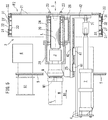
FIG. 4A is a vertical cross-sectional view showing a fiber-stacking drum, etc., while in operation, andFIG. 4B is a cross-sectional view showing the details of a fiber-stacking ring. -
FIG. 5 is a vertical cross-sectional view showing the fiber-stacking drum, etc., during replacement. -
FIG. 6 is a schematic side view showing a method for removing a fiber-stacking ring. -
FIG. 7 is a schematic side view showing a method for installing a fiber-stacking ring. - Note that sliders and bearing inner and outer races are colored in gray for ease of understanding of the drawings.
- Preferably, with the apparatus of the present invention, the fiber-stacking
drum 2 further includes a cylindrical bearingcylinder 24 for rotatably supporting therotation shaft 20; and
the fiber-stackingdrum 2 including the bearingcylinder 24 is supported by thefixed frame 5 so as to be slidable relative to thefixed frame 5 in the axial direction S. - In this case, there is no need for a configuration where the
rotation shaft 20 can slide in the axial direction S relative to the bearingcylinder 24. Therefore, it is possible with the bearingcylinder 24 to reliably axially support therotation shaft 20, which rotates at a high speed. - More preferably, an output section M1 of a motor M for rotating the
rotation shaft 20 is linked to the other end of therotation shaft 20; and
the motor M, together with the bearingcylinder 24, is supported by thefixed frame 5 so as to be slidable relative to thefixed frame 5 in the axial direction S. - In this case, the replacement can be done while the motor M remains linked to the
rotation shaft 20. Thus, it is possible to realize a stable rotation of the motor M and therotation shaft 20, which rotate at a high speed. - More preferably, the manufacturing apparatus further includes:
- a
slider 25 fixed to the bearingcylinder 24; and - a
linear guide 41 for guiding theslider 25 in a direction parallel to the axial direction S. - In this case, it is possible to reliably and easily slide the fiber-stacking
drum 2 in the axial direction S. - More preferably, the manufacturing apparatus further includes an
actuator 7 for sliding theslider 25 along thelinear guide 41. - In this case, it is possible to slide the fiber-stacking
drum 2 in the axial direction S by operating theactuator 7. - Any feature illustrated and/or depicted in conjunction with one of the aforementioned aspects or the following embodiments may be used in the same or similar form in one or more of the other aspects or other embodiments, and/or may be used in combination with, or in place of, any feature of the other aspects or embodiments.
- The present invention will be understood more clearly from the following description of preferred embodiments taken in conjunction with the accompanying drawings. Note however that the embodiments and the drawings are merely illustrative and should not be taken to define the scope of the present invention. The scope of the present invention shall be defined only by the appended claims. In the accompanying drawings, like reference numerals denote like components throughout the plurality of figures.
- One embodiment of the present invention will now be described with reference to the drawings.
- An absorbent core to be manufactured by the present manufacturing apparatus is used as the core of incontinence pads as well as disposable pants and diapers, for example, and has an hourglass-like shape, for example.
- As shown in
FIG. 1 , the present manufacturing apparatus includes adispenser 1, a fiber-stackingdrum 2, asuction chamber 6, aguide roll 8 and aconveyer 9. - The
dispenser 1 includes a dome-shapedcase 10 and a defibrator (a defibration machine) 11. Thedefibrator 11 defibrates (crushes) a pulp dispensed from upstream into a fibrous material to produce a fluff pulp (fiber). The fluff pulp fills up thecase 10, and with thesuction chamber 6 of the fiber-stackingdrum 2 set at a negative pressure, the fluff pulp is stacked onto the fiber-stackingring 22 of the fiber-stackingdrum 2. Such defibration and fiber-stacking are techniques well known in the art, and are disclosed inJP2009-112438A - Note that a granular material of a polymer compound having a high absorption capacity called "SAP" (super absorbent polymer particles) may be added as a material of the absorbent core.
- The fiber-stacking
ring 22 ofFIG. 4A is generally cylindrical and includes a plurality of, or a large number of,segments 3 arranged along the circumferential direction R ofFIG. 1 . - For the sake of illustration,
FIG. 2 shows components of onesegment 3 disassembled and arranged in a flat layout. Eachsegment 3 includes atemplate 31, amesh member 32 and alattice member 33, etc. - A large number of, or countless, through
holes 32a are formed in themesh member 32 by performing an etching process well known in the art on a thin metal plate. The throughholes 32a are sized so that they allow air therethrough but can receive the fiber and SAP. For example, a pair oftemplates 31 are provided and arranged on the outer circumferential surface side of themesh member 32, forming a fiber-stackingdepression 30. - Note that for the sake of illustration, meshes of the
mesh member 32 are shown enlarged and only some of them are shown. - The pair of
templates depression 30. The fiber stacked in the fiber-stackingdepression 30 becomes an absorbent core of an individual worn article. - That is, the fiber-stacking
drum 2 ofFIG. 1 , while continuously rotating in the circumferential direction R, sucks the fiber dispensed from thedispenser 1 toward thesuction chamber 6 on the inner side from an outercircumferential surface 2f (FIG. 4A ) of the fiber-stackingring 22, thereby continuously stacking the fiber onto the outercircumferential surface 2f of a predetermined fiber-stackingdepression 30 ofFIG. 4B . That is, the fiber is stacked on the outercircumferential surface 2f of the cylindrical fiber-stackingring 22 defining the fiber-stackingdepression 30. - The
lattice member 33 ofFIG. 2 is formed offrames 33a extending in the width direction D and the circumferential direction R so as not to inhibit suction of the fiber. Thelattice member 33 is in contact with themesh member 32 and supports the inner circumferential surface of themesh member 32, which is vulnerable to an external force. - As shown in
FIG. 3 , thesuction chamber 6 is arranged over a predetermined section of the fiber-stackingdrum 2 in the circumferential direction R, and is connected to a negative pressure source (not shown) via a plurality ofducts 61 so that the inside of the chamber is at a negative pressure. - As shown in
FIG. 4A , thesuction chamber 6 is arranged close to the inner circumference side of the fiber-stackingring 22 of the fiber-stackingdrum 2. That is, thesuction chamber 6 is fixed to the fixedframe 5, wherein thesuction chamber 6 is in contact with the inner circumference of (arranged on the inner side of) the fiber-stackingring 22 and produces a suction force exerting from the outer circumference of the fiber-stackingring 22 toward the inner circumference of the fiber-stackingring 22. For example, thissuction chamber 6 may be fixed to the fixedframe 5 via theducts 61. - The fixed
frame 5 is a vertical place well known in the art that supports the various machine parts of the apparatus for manufacturing a disposable worn article. As will be described below, the fixedframe 5 rotatably supports the fiber-stackingdrum 2. - As shown in
FIG. 4A , the fiber-stackingdrum 2 includes arotation shaft 20 that is rotated, awheel 21 attached to the distal end (one end) of therotation shaft 20, and the cylindrical fiber-stackingring 22. - The fiber-stacking
ring 22 is provided on the outer circumference portion along the edge of thewheel 21 for stacking the fiber. Thewheel 21 is removably attached to the distal end (one end) of therotation shaft 20 via afastener 23. For example, thefastener 23 may include a plurality of bolts, which pass through thewheel 21 and are screwed into the distal end of therotation shaft 20. - As shown in
FIG. 4A and FIG. 4B , the fiber-stackingring 22 includes a pair of annular frame rings 29. A large number ofsegments 3 are arranged next to each other in the circumferential direction R as shown inFIG. 1 along the annular frame rings 29. - As shown in
FIG. 4B , the pair of frame rings 29, 29 are linked to each other in the axial direction S via thelattice member 33. Thetemplate 31, themesh member 32 and thelattice member 33 of eachsegment 3 are fixed between the pair of frame rings 29, 29 in the axial direction S. - As shown in
FIG. 4A , the fiber-stackingdrum 2 further includes a cylindrical bearing cylinder (a cylindrical bearing sleeve) 24 that rotatably supports therotation shaft 20. An output section M1 of a servomotor M that rotates therotation shaft 20 is linked to the proximal end (the other end) of therotation shaft 20 via a decelerator G and a coupling J. The motor M is fixed to thebearing cylinder 24 via the decelerator G. - A
link portion 26 is attached to thebearing cylinder 24, and acase 28 extending in the axial direction S is attached to one end of thelink portion 26. A portion of therotation shaft 20 and the coupling J are accommodated inside thecase 28, and the opening of thecase 28 is covered (lidded) by the decelerator G. That is, therotation shaft 20 and the coupling J are accommodated in the space that is formed by the bearingcylinder 24, thecase 28 and the decelerator G, and it is therefore possible to prevent the crushed fluff pulp (fiber) from being stuck on therotation shaft 20, etc. - The bearing
cylinder 24 is fixed to aslider 25. That is, theslider 25 is attached to thebearing cylinder 24 via thelink portion 26 and a movingplate 42. Theslider 25 is guided by alinear guide 41 in the direction parallel to the axial direction S. Thelinear guide 41 is fixed to the fixedframe 5 via abase 4. Note that theslider 25 is colored in gray in the figures. - An
actuator 7 such as an air cylinder is attached to thebase 4. That is, theactuator 7 is fixed to the fixedframe 5 via thebase 4. In other words, theactuator 7 is attached to a non-rotating portion of the present manufacturing apparatus. - The
actuator 7 slides the motor M, the bearingcylinder 24 and the fiber-stackingdrum 2 in the axial direction S via theslider 25, the movingplate 42 and thelink portion 26. - For example, the moving
plate 42 is fixed to the distal end of arod 71 of anair cylinder 7, and the fiber-stackingdrum 2 slides between the operation position P1 ofFIG. 4A and the replacement position P2 ofFIG. 5 . - Thus, the fiber-stacking
drum 2, together with the motor M and the bearingcylinder 24, is supported by the fixedframe 5 so as to be slidable relative to the fixedframe 5 in the axial direction S, in which the axial line L of therotation shaft 20 extends. - In the present embodiment, since the axial line L of the
rotation shaft 20 and the axial line L of the motor M are arranged on the same axial line, the bearingcylinder 24, the motor M and the fiber-stackingdrum 2 can easily slide in the axial direction S. - Next, a method for manufacturing an absorbent core will be described briefly.
- While manufacturing an absorbent core, the fiber-stacking
drum 2 is set to the operation position P1 ofFIG. 4A . - A carrier web W is continuously introduced from the
guide roll 8 onto the fiber-stackingdrum 2 ofFIG. 1 . On the other hand, while the fiber-stackingdrum 2 continuously rotates in the circumferential direction R, the fiber dispensed from thedispenser 1 is sucked by thesuction chamber 6 toward the inside from the outercircumferential surface 2f of the fiber-stacking drum 2 (the outercircumferential surface 2f of the fiber-stacking depression 30). Thus, the fiber is continuously stacked on the outercircumferential surface 2f (FIG. 4B ) of the fiber-stackingdepression 30, thereby producing a continuous core C. - In
FIG. 1 , as well known in the art, the carrier web W dispensed from theguide roll 8 is laid over the stacked continuous core C. Then, the continuous core C and the carrier web W are rolled out of the fiber-stackingdrum 2 as an integral material. Then, as well known in the art, it may be severed into absorbent cores of individual worn articles on the downstream side (not shown). Instead of producing the continuous core C, individual absorbent cores may be produced by fiber-stacking on the fiber-stackingdrum 2. - Next, a replacement method for replacing the
wheel 21 and the fiber-stackingring 22 of the fiber-stackingdrum 2 of the manufacturing apparatus. - In order to replace, first, the operator slides the fiber-stacking
drum 2 ofFIG. 4A from the operation position P1 to the replacement position P2 ofFIG. 5 . That is, thewheel 21 and the fiber-stackingring 22 are moved from the operation position P1 to the replacement position P2 ofFIG. 5 by sliding the motor M, the bearingcylinder 24 and the fiber-stackingdrum 2 in the first direction D1 along the axial line L by protruding therod 71 of theair cylinder 7 ofFIG. 4A . Thus, thewheel 21 and the fiber-stackingring 22 move to a position away from the dispenser 1 (FIG. 1 ). - Note that the first direction D1 means the direction from the proximal end (the proximal end of the rotation shaft 20) to which the output section M1 of the motor M is linked toward one end (one end of the rotation shaft 20) to which the
wheel 21 is attached. - Then, the operator loosens the
fastener 23 ofFIG. 5 and removes thewheel 21 and the fiber-stackingring 22 from therotation shaft 20. As shown inFIG. 6 , thewheel 21 and the fiber-stackingring 22 having been removed are moved onto afirst platform truck 101. - The operator moves another wheel (a substitute wheel) 21A and another fiber-stacking ring (a substitute fiber-stacking ring) 22A of
FIG. 7 from asecond platform truck 102 and attaches them to the distal end of therotation shaft 20, in place of thewheel 21 and the fiber-stackingring 22 ofFIG. 6 having been removed. Thesegments 3 on the other fiber-stackingring 22A may be of a different pattern from the segments of the removed fiber-stackingring 22. - Thereafter, through an opposite procedure from the removal, the operator actuates the
actuator 7 to slide therotation shaft 20, to which theother wheel 21A and the other fiber-stackingring 22A have been attached, together with the motor M and the bearingcylinder 24 ofFIG. 5 , in the second direction D2, which is opposite to the first direction D1. - Thus, replacement can be done quickly when manufacturing worn articles of different sizes, for example.
- While one embodiment has been described above with reference to the drawings, obvious variations and modifications will readily occur to those skilled in the art upon reading the present specification.
- For example, the replacement of the wheel and the fiber-stacking ring may be done for a change in the shape of the absorbent core, instead of a change in size.
- When replacing the fiber-stacking ring, only segments may be replaced without replacing the wheel.
- A plurality of through holes may be provided in the wheel for reducing the weight thereof.
- Thus, such variations and modifications shall fall within the scope of the present invention as defined by the appended claims.
- The present invention is applicable to an apparatus for manufacturing an absorbent core of a disposable worn article.
-
- 1: Dispenser, 10: Case, 11: Defibrator
- 2: Fiber-stacking drum, 2f: Outer circumferential surface, 20: Rotation shaft, 21: Wheel
- 22: Fiber-stacking ring, 29: Frame ring
- 21A: Another wheel, 22A: Another fiber-stacking ring
- 23: Fastener, 24: Bearing cylinder, 25: Slider, 26: Link portion, 28: Case
- 3: Segment, 30: Fiber-stacking depression, 31: Template, 32: Mesh member
- 32f: Inner circumferential surface side, 33: Lattice member, 33a: Frame
- 4: Base, 41: Linear guide, 42: Moving plate
- 5: Fixed frame, 6: Suction chamber, 61: Duct
- 7: Actuator, 71: Rod, 8: Guide roll, 9: Conveyer
- 101, 102: Platform truck
- C: Continuous core, L: Axial line, S: Axial direction
- M: Motor, Ml: Output section, G: Decelerator, J: Coupling
- P1: Operation position, P2: Replacement position
- R: Circumferential direction, D: Width direction, D1: First direction, D2: Second direction
- W: Carrier web
Claims (8)
- An apparatus for manufacturing an absorbent core of a disposable worn article, comprising:a dispenser 1 for dispensing a crushed fiber;a fiber-stacking drum 2 for stacking the fiber dispensed from the dispenser 1 on an outer circumferential surface 2f while sucking the fiber from the outer circumferential surface 2f toward an inside; anda fixed frame 5 for rotatably supporting the fiber-stacking drum 2, wherein the fiber-stacking drum 2 includes:a rotation shaft 20 that is rotated;a wheel 21 attached to one end of the rotation shaft 20; anda cylindrical fiber-stacking ring 22 provided on an outer circumference portion of the wheel 21 for stacking the fiber, wherein:a suction chamber 6 is fixed to the fixed frame 5, wherein the suction chamber 6 is arranged on an inner side of the fiber-stacking ring 22 and produces a suction force from an outer circumference toward an inner circumference of the fiber-stacking ring 22;the fiber-stacking drum 2 is supported by the fixed frame 5 so as to be slidable relative to the fixed frame 5 in an axial direction S, in which an axial line L of the rotation shaft 20 extends; andthe wheel 21 is removably attached to the one end of the rotation shaft 20 via a fastener 23.
- The manufacturing apparatus according to claim 1, wherein:the fiber-stacking drum 2 further includes a cylindrical bearing cylinder 24 for rotatably supporting the rotation shaft 20; andthe fiber-stacking drum 2 including the bearing cylinder 24 is supported by the fixed frame 5 so as to be slidable relative to the fixed frame 5 in the axial direction S.
- The manufacturing apparatus according to claim 2, wherein:an output section M1 of a motor M for rotating the rotation shaft 20 is linked to another end of the rotation shaft 20; andthe motor M, together with the bearing cylinder 24, is supported by the fixed frame 5 so as to be slidable relative to the fixed frame 5 in the axial direction S.
- The manufacturing apparatus according to claim 3, further comprising:a slider 25 fixed to the bearing cylinder 24; anda linear guide 41 for guiding the slider 25 in a direction parallel to the axial direction S.
- The manufacturing apparatus according to claim 4, further comprising an actuator 7 for sliding the slider 25 along the linear guide 41.
- The manufacturing apparatus according to claim 1, wherein:the fiber-stacking drum 2 further includes a cylindrical bearing cylinder 24 for rotatably supporting the rotation shaft 20;an output section M1 of a motor M for rotating the rotation shaft 20 is linked to another end of the rotation shaft 20;the motor M is fixed to the bearing cylinder 24;a slider 25 is attached to the bearing cylinder 24;a linear guide 41 is fixed to the fixed frame 5, the linear guide 41 guiding the slider 25 in a direction parallel to the axial direction S; andan actuator 7 is fixed to the fixed frame 5, the actuator 7 sliding the fiber-stacking drum 2 including the bearing cylinder 24 and the motor M in the axial direction S via the slider 25.
- A replacement method for replacing the wheel 21 and the fiber-stacking ring 22 of the fiber-stacking drum 2 of the manufacturing apparatus of claim 1, the replacement method comprising the steps of:moving the fiber-stacking drum 2 at an operation position P1 to a replacement position P2 away from the dispenser 1 by sliding the fiber-stacking drum 2 in a first direction D1 along the axial line L;loosening the fastener 23 to remove the wheel 21 and the fiber-stacking ring 22 from the rotation shaft 20;attaching another wheel 21A and another fiber-stacking ring 22A to the one end of the rotation shaft 20, in place of the wheel 21 and the fiber-stacking ring 22 having been removed; andsliding the rotation shaft 20, to which the other wheel 21A and the other fiber-stacking ring 22A have been attached, in a second direction D2, which is opposite to the first direction D1.
- A replacement method for replacing the wheel 21 and the fiber-stacking ring 22 of the fiber-stacking drum 2 of the manufacturing apparatus of claim 6, the replacement method comprising the steps of:actuating the actuator 7 to slide the motor M, the bearing cylinder 24 and the fiber-stacking drum 2 at an operation position P1 in a first direction D1 along the axial line L so as to move the fiber-stacking ring 22 to a replacement position P2 away from the dispenser 1;loosening the fastener 23 to remove the wheel 21 and the fiber-stacking ring 22 from the rotation shaft 20;attaching another wheel 21A and another fiber-stacking ring 22A to the one end of the rotation shaft 20, in place of the wheel 21 and the fiber-stacking ring 22 having been removed; andactuating the actuator 7 to slide the rotation shaft 20, to which the other wheel 21A and the other fiber-stacking ring 22A have been attached, together with the motor M and the bearing cylinder 24, in a second direction D2, which is opposite to the first direction D1.
Applications Claiming Priority (2)
| Application Number | Priority Date | Filing Date | Title |
|---|---|---|---|
| JP2017236737 | 2017-12-11 | ||
| PCT/JP2018/043140 WO2019116852A1 (en) | 2017-12-11 | 2018-11-22 | Apparatus for manufacturing absorbent core of disposable wearing article and exchange method for exchanging part of said apparatus |
Publications (2)
| Publication Number | Publication Date |
|---|---|
| EP3725278A1 true EP3725278A1 (en) | 2020-10-21 |
| EP3725278A4 EP3725278A4 (en) | 2021-08-25 |
Family
ID=66819178
Family Applications (1)
| Application Number | Title | Priority Date | Filing Date |
|---|---|---|---|
| EP18888016.5A Pending EP3725278A4 (en) | 2017-12-11 | 2018-11-22 | APPARATUS FOR MANUFACTURING AN ABSORBENT CORE OF AN ARTICLE TO BE WEAR DISPOSABLE AND EXCHANGE PROCEDURE FOR EXCHANGING PART OF SAID APPARATUS |
Country Status (6)
| Country | Link |
|---|---|
| US (1) | US11793681B2 (en) |
| EP (1) | EP3725278A4 (en) |
| JP (1) | JP7256993B2 (en) |
| CN (1) | CN111432766B (en) |
| MX (1) | MX2020005722A (en) |
| WO (1) | WO2019116852A1 (en) |
Family Cites Families (14)
| Publication number | Priority date | Publication date | Assignee | Title |
|---|---|---|---|---|
| US4666647A (en) * | 1985-12-10 | 1987-05-19 | Kimberly-Clark Corporation | Apparatus and process for forming a laid fibrous web |
| ATE82597T1 (en) * | 1985-12-10 | 1992-12-15 | Kimberly Clark Co | APPARATUS AND PROCESS FOR PRODUCTION OF A FIBER WEB. |
| US4995141A (en) | 1990-07-16 | 1991-02-26 | Paper Converting Machine Company | Method and apparatus for facilitating product changeover in the manufacture of fluff pads for disposable diapers |
| JPH0749335B2 (en) * | 1992-05-07 | 1995-05-31 | 東亜機工株式会社 | Powder and dusting device |
| JP4372734B2 (en) | 2005-08-11 | 2009-11-25 | 花王株式会社 | Processing unit fixing system |
| JP4974522B2 (en) | 2005-12-26 | 2012-07-11 | 大王製紙株式会社 | Absorber manufacturing equipment |
| ES2338264T3 (en) * | 2007-04-05 | 2010-05-05 | Snap-On Equipment Srl A Unico Socio | DEVICE FOR CHANGING TIRES. |
| JP5046865B2 (en) | 2007-11-05 | 2012-10-10 | 花王株式会社 | Absorbent article and manufacturing method thereof |
| JP5396321B2 (en) * | 2010-03-26 | 2014-01-22 | ユニ・チャーム株式会社 | Absorber manufacturing equipment |
| EP2386277B1 (en) * | 2010-04-20 | 2013-11-13 | The Procter and Gamble Company | Apparatus and method for receiving and transferring solid material |
| JP5767821B2 (en) * | 2011-02-04 | 2015-08-19 | ユニ・チャーム株式会社 | Absorber manufacturing apparatus and manufacturing method |
| JP5808164B2 (en) * | 2011-06-24 | 2015-11-10 | 中村留精密工業株式会社 | Tool and automatic tool changer |
| CN202751508U (en) * | 2012-07-20 | 2013-02-27 | 江苏金卫机械设备有限公司 | Cotton core die wheel system |
| WO2018173118A1 (en) | 2017-03-21 | 2018-09-27 | ユニ・チャーム株式会社 | Method and device for manufacturing absorptive article |
-
2018
- 2018-11-22 CN CN201880078564.3A patent/CN111432766B/en active Active
- 2018-11-22 JP JP2019559519A patent/JP7256993B2/en active Active
- 2018-11-22 WO PCT/JP2018/043140 patent/WO2019116852A1/en not_active Ceased
- 2018-11-22 EP EP18888016.5A patent/EP3725278A4/en active Pending
- 2018-11-22 MX MX2020005722A patent/MX2020005722A/en unknown
- 2018-11-22 US US16/768,134 patent/US11793681B2/en active Active
Also Published As
| Publication number | Publication date |
|---|---|
| EP3725278A4 (en) | 2021-08-25 |
| MX2020005722A (en) | 2020-08-13 |
| CN111432766A (en) | 2020-07-17 |
| JPWO2019116852A1 (en) | 2020-12-03 |
| JP7256993B2 (en) | 2023-04-13 |
| WO2019116852A1 (en) | 2019-06-20 |
| US11793681B2 (en) | 2023-10-24 |
| CN111432766B (en) | 2021-12-21 |
| US20210169705A1 (en) | 2021-06-10 |
Similar Documents
| Publication | Publication Date | Title |
|---|---|---|
| JP6888080B2 (en) | A device for transferring and rotating an object | |
| JP4613064B2 (en) | Apparatus and mold for the formation of air-forming fibrous webs | |
| EP2043574B1 (en) | An apparatus and method for forming air-laid absorbent cores | |
| EP4112518A1 (en) | Method and apparatus for depositing discrete elements on a support element | |
| ITBO20110112A1 (en) | LEATHER CUTTING MACHINE | |
| EP2707544B1 (en) | Seal assembly | |
| US11793681B2 (en) | Apparatus for manufacturing absorbent core of disposable worn article, and replacement method for replacing part of the apparatus | |
| JPH11124761A (en) | Device for air laying fibrous material or particle material | |
| DK2659868T3 (en) | Method and device for placing single transfer insert | |
| JP5892883B2 (en) | Absorber manufacturing equipment | |
| EP3184679A1 (en) | Method for operating an open-ended rotor spinning device and open ended rotor spinning machine with a multitude of open-ended rotor spinning devices side by side | |
| CN104005095B (en) | A kind of big device of automatic silk reeling machine | |
| US7553146B2 (en) | Apparatus for making air-laid structures | |
| WO2013058196A1 (en) | Fiber stacking device | |
| WO2008061178A2 (en) | Apparatus for making air-laid structures | |
| CN101484106A (en) | A mat-forming wheel | |
| JP5743282B2 (en) | Absorber manufacturing equipment | |
| EP2758581B1 (en) | Apparatus for pliabilizing knitted or woven materials | |
| JP6513533B2 (en) | Stacking device | |
| CN206184544U (en) | Ring roller grinds convenient to maintenance | |
| CN220922253U (en) | Frock is changed to cigarette machine detection wheel non-dismantling formula sealing washer | |
| CN203878240U (en) | Large culture device of automatic silk reeling machine | |
| CN213476282U (en) | Base cloth fiber leveling device based on fabric layer | |
| JP2019504740A (en) | Unit for supplying side flaps of sanitary absorbent articles and method for changing the format of a supply unit | |
| CN206542640U (en) | A kind of quick-detachable multiple nip drum wheel assembly of screening cover attachment |
Legal Events
| Date | Code | Title | Description |
|---|---|---|---|
| STAA | Information on the status of an ep patent application or granted ep patent |
Free format text: STATUS: THE INTERNATIONAL PUBLICATION HAS BEEN MADE |
|
| PUAI | Public reference made under article 153(3) epc to a published international application that has entered the european phase |
Free format text: ORIGINAL CODE: 0009012 |
|
| STAA | Information on the status of an ep patent application or granted ep patent |
Free format text: STATUS: REQUEST FOR EXAMINATION WAS MADE |
|
| 17P | Request for examination filed |
Effective date: 20200525 |
|
| AK | Designated contracting states |
Kind code of ref document: A1 Designated state(s): AL AT BE BG CH CY CZ DE DK EE ES FI FR GB GR HR HU IE IS IT LI LT LU LV MC MK MT NL NO PL PT RO RS SE SI SK SM TR |
|
| AX | Request for extension of the european patent |
Extension state: BA ME |
|
| DAV | Request for validation of the european patent (deleted) | ||
| DAX | Request for extension of the european patent (deleted) | ||
| A4 | Supplementary search report drawn up and despatched |
Effective date: 20210722 |
|
| RIC1 | Information provided on ipc code assigned before grant |
Ipc: A61F 13/15 20060101AFI20210716BHEP |
|
| STAA | Information on the status of an ep patent application or granted ep patent |
Free format text: STATUS: EXAMINATION IS IN PROGRESS |
|
| 17Q | First examination report despatched |
Effective date: 20221222 |