EP3725222B1 - System and ventilator for real-time determination of local stress of a lung during artificial respiration - Google Patents
System and ventilator for real-time determination of local stress of a lung during artificial respiration Download PDFInfo
- Publication number
- EP3725222B1 EP3725222B1 EP20000151.9A EP20000151A EP3725222B1 EP 3725222 B1 EP3725222 B1 EP 3725222B1 EP 20000151 A EP20000151 A EP 20000151A EP 3725222 B1 EP3725222 B1 EP 3725222B1
- Authority
- EP
- European Patent Office
- Prior art keywords
- electrical impedance
- ventilator
- value
- eit
- specific
- Prior art date
- Legal status (The legal status is an assumption and is not a legal conclusion. Google has not performed a legal analysis and makes no representation as to the accuracy of the status listed.)
- Active
Links
- 210000004072 lung Anatomy 0.000 title claims description 120
- 230000029058 respiratory gaseous exchange Effects 0.000 title claims description 50
- 238000009423 ventilation Methods 0.000 claims description 52
- 238000002593 electrical impedance tomography Methods 0.000 claims description 30
- 230000000241 respiratory effect Effects 0.000 claims description 24
- 230000008859 change Effects 0.000 claims description 11
- 210000000038 chest Anatomy 0.000 claims description 7
- 230000001419 dependent effect Effects 0.000 claims description 4
- 238000000034 method Methods 0.000 description 30
- 239000007789 gas Substances 0.000 description 22
- 238000005259 measurement Methods 0.000 description 16
- QVGXLLKOCUKJST-UHFFFAOYSA-N atomic oxygen Chemical compound [O] QVGXLLKOCUKJST-UHFFFAOYSA-N 0.000 description 10
- 229910052760 oxygen Inorganic materials 0.000 description 9
- 239000001301 oxygen Substances 0.000 description 9
- CURLTUGMZLYLDI-UHFFFAOYSA-N Carbon dioxide Chemical compound O=C=O CURLTUGMZLYLDI-UHFFFAOYSA-N 0.000 description 8
- 230000008569 process Effects 0.000 description 6
- 238000010606 normalization Methods 0.000 description 5
- 229910002092 carbon dioxide Inorganic materials 0.000 description 4
- 239000001569 carbon dioxide Substances 0.000 description 4
- 230000001276 controlling effect Effects 0.000 description 4
- 230000000694 effects Effects 0.000 description 4
- 238000002847 impedance measurement Methods 0.000 description 4
- 238000003325 tomography Methods 0.000 description 4
- 239000000853 adhesive Substances 0.000 description 3
- 230000001070 adhesive effect Effects 0.000 description 3
- 239000012790 adhesive layer Substances 0.000 description 3
- 238000004364 calculation method Methods 0.000 description 3
- 238000004891 communication Methods 0.000 description 3
- 230000008878 coupling Effects 0.000 description 3
- 238000010168 coupling process Methods 0.000 description 3
- 238000005859 coupling reaction Methods 0.000 description 3
- 230000007423 decrease Effects 0.000 description 3
- 238000003384 imaging method Methods 0.000 description 3
- 239000010410 layer Substances 0.000 description 3
- 210000003281 pleural cavity Anatomy 0.000 description 3
- 238000005516 engineering process Methods 0.000 description 2
- 239000004753 textile Substances 0.000 description 2
- 208000007123 Pulmonary Atelectasis Diseases 0.000 description 1
- 210000004712 air sac Anatomy 0.000 description 1
- 238000004458 analytical method Methods 0.000 description 1
- 230000005540 biological transmission Effects 0.000 description 1
- 230000037396 body weight Effects 0.000 description 1
- 238000011161 development Methods 0.000 description 1
- 230000018109 developmental process Effects 0.000 description 1
- 210000003238 esophagus Anatomy 0.000 description 1
- 230000006870 function Effects 0.000 description 1
- 230000005484 gravity Effects 0.000 description 1
- 230000003434 inspiratory effect Effects 0.000 description 1
- 238000005399 mechanical ventilation Methods 0.000 description 1
- 238000012545 processing Methods 0.000 description 1
- 230000001105 regulatory effect Effects 0.000 description 1
- 230000004044 response Effects 0.000 description 1
- 238000010321 sleep therapy Methods 0.000 description 1
- 230000002123 temporal effect Effects 0.000 description 1
- 238000002560 therapeutic procedure Methods 0.000 description 1
- 238000011144 upstream manufacturing Methods 0.000 description 1
- 238000012800 visualization Methods 0.000 description 1
Images


Classifications
-
- A—HUMAN NECESSITIES
- A61—MEDICAL OR VETERINARY SCIENCE; HYGIENE
- A61B—DIAGNOSIS; SURGERY; IDENTIFICATION
- A61B5/00—Measuring for diagnostic purposes; Identification of persons
- A61B5/05—Detecting, measuring or recording for diagnosis by means of electric currents or magnetic fields; Measuring using microwaves or radio waves
- A61B5/053—Measuring electrical impedance or conductance of a portion of the body
- A61B5/0536—Impedance imaging, e.g. by tomography
-
- A—HUMAN NECESSITIES
- A61—MEDICAL OR VETERINARY SCIENCE; HYGIENE
- A61M—DEVICES FOR INTRODUCING MEDIA INTO, OR ONTO, THE BODY; DEVICES FOR TRANSDUCING BODY MEDIA OR FOR TAKING MEDIA FROM THE BODY; DEVICES FOR PRODUCING OR ENDING SLEEP OR STUPOR
- A61M16/00—Devices for influencing the respiratory system of patients by gas treatment, e.g. mouth-to-mouth respiration; Tracheal tubes
-
- A—HUMAN NECESSITIES
- A61—MEDICAL OR VETERINARY SCIENCE; HYGIENE
- A61B—DIAGNOSIS; SURGERY; IDENTIFICATION
- A61B5/00—Measuring for diagnostic purposes; Identification of persons
- A61B5/0033—Features or image-related aspects of imaging apparatus classified in A61B5/00, e.g. for MRI, optical tomography or impedance tomography apparatus; arrangements of imaging apparatus in a room
- A61B5/0036—Features or image-related aspects of imaging apparatus classified in A61B5/00, e.g. for MRI, optical tomography or impedance tomography apparatus; arrangements of imaging apparatus in a room including treatment, e.g., using an implantable medical device, ablating, ventilating
-
- A—HUMAN NECESSITIES
- A61—MEDICAL OR VETERINARY SCIENCE; HYGIENE
- A61B—DIAGNOSIS; SURGERY; IDENTIFICATION
- A61B5/00—Measuring for diagnostic purposes; Identification of persons
- A61B5/0033—Features or image-related aspects of imaging apparatus classified in A61B5/00, e.g. for MRI, optical tomography or impedance tomography apparatus; arrangements of imaging apparatus in a room
- A61B5/004—Features or image-related aspects of imaging apparatus classified in A61B5/00, e.g. for MRI, optical tomography or impedance tomography apparatus; arrangements of imaging apparatus in a room adapted for image acquisition of a particular organ or body part
-
- A—HUMAN NECESSITIES
- A61—MEDICAL OR VETERINARY SCIENCE; HYGIENE
- A61B—DIAGNOSIS; SURGERY; IDENTIFICATION
- A61B5/00—Measuring for diagnostic purposes; Identification of persons
- A61B5/08—Detecting, measuring or recording devices for evaluating the respiratory organs
- A61B5/0803—Recording apparatus specially adapted therefor
-
- A—HUMAN NECESSITIES
- A61—MEDICAL OR VETERINARY SCIENCE; HYGIENE
- A61B—DIAGNOSIS; SURGERY; IDENTIFICATION
- A61B5/00—Measuring for diagnostic purposes; Identification of persons
- A61B5/08—Detecting, measuring or recording devices for evaluating the respiratory organs
- A61B5/0809—Detecting, measuring or recording devices for evaluating the respiratory organs by impedance pneumography
-
- A—HUMAN NECESSITIES
- A61—MEDICAL OR VETERINARY SCIENCE; HYGIENE
- A61B—DIAGNOSIS; SURGERY; IDENTIFICATION
- A61B5/00—Measuring for diagnostic purposes; Identification of persons
- A61B5/08—Detecting, measuring or recording devices for evaluating the respiratory organs
- A61B5/085—Measuring impedance of respiratory organs or lung elasticity
-
- A—HUMAN NECESSITIES
- A61—MEDICAL OR VETERINARY SCIENCE; HYGIENE
- A61B—DIAGNOSIS; SURGERY; IDENTIFICATION
- A61B5/00—Measuring for diagnostic purposes; Identification of persons
- A61B5/68—Arrangements of detecting, measuring or recording means, e.g. sensors, in relation to patient
- A61B5/6801—Arrangements of detecting, measuring or recording means, e.g. sensors, in relation to patient specially adapted to be attached to or worn on the body surface
- A61B5/6802—Sensor mounted on worn items
- A61B5/6803—Head-worn items, e.g. helmets, masks, headphones or goggles
-
- A—HUMAN NECESSITIES
- A61—MEDICAL OR VETERINARY SCIENCE; HYGIENE
- A61B—DIAGNOSIS; SURGERY; IDENTIFICATION
- A61B5/00—Measuring for diagnostic purposes; Identification of persons
- A61B5/74—Details of notification to user or communication with user or patient ; user input means
- A61B5/742—Details of notification to user or communication with user or patient ; user input means using visual displays
- A61B5/743—Displaying an image simultaneously with additional graphical information, e.g. symbols, charts, function plots
-
- A—HUMAN NECESSITIES
- A61—MEDICAL OR VETERINARY SCIENCE; HYGIENE
- A61M—DEVICES FOR INTRODUCING MEDIA INTO, OR ONTO, THE BODY; DEVICES FOR TRANSDUCING BODY MEDIA OR FOR TAKING MEDIA FROM THE BODY; DEVICES FOR PRODUCING OR ENDING SLEEP OR STUPOR
- A61M16/00—Devices for influencing the respiratory system of patients by gas treatment, e.g. mouth-to-mouth respiration; Tracheal tubes
- A61M16/0057—Pumps therefor
-
- A—HUMAN NECESSITIES
- A61—MEDICAL OR VETERINARY SCIENCE; HYGIENE
- A61M—DEVICES FOR INTRODUCING MEDIA INTO, OR ONTO, THE BODY; DEVICES FOR TRANSDUCING BODY MEDIA OR FOR TAKING MEDIA FROM THE BODY; DEVICES FOR PRODUCING OR ENDING SLEEP OR STUPOR
- A61M16/00—Devices for influencing the respiratory system of patients by gas treatment, e.g. mouth-to-mouth respiration; Tracheal tubes
- A61M16/021—Devices for influencing the respiratory system of patients by gas treatment, e.g. mouth-to-mouth respiration; Tracheal tubes operated by electrical means
- A61M16/022—Control means therefor
- A61M16/024—Control means therefor including calculation means, e.g. using a processor
-
- A—HUMAN NECESSITIES
- A61—MEDICAL OR VETERINARY SCIENCE; HYGIENE
- A61M—DEVICES FOR INTRODUCING MEDIA INTO, OR ONTO, THE BODY; DEVICES FOR TRANSDUCING BODY MEDIA OR FOR TAKING MEDIA FROM THE BODY; DEVICES FOR PRODUCING OR ENDING SLEEP OR STUPOR
- A61M16/00—Devices for influencing the respiratory system of patients by gas treatment, e.g. mouth-to-mouth respiration; Tracheal tubes
- A61M16/10—Preparation of respiratory gases or vapours
- A61M16/1005—Preparation of respiratory gases or vapours with O2 features or with parameter measurement
-
- A—HUMAN NECESSITIES
- A61—MEDICAL OR VETERINARY SCIENCE; HYGIENE
- A61B—DIAGNOSIS; SURGERY; IDENTIFICATION
- A61B5/00—Measuring for diagnostic purposes; Identification of persons
- A61B5/08—Detecting, measuring or recording devices for evaluating the respiratory organs
- A61B5/0816—Measuring devices for examining respiratory frequency
-
- A—HUMAN NECESSITIES
- A61—MEDICAL OR VETERINARY SCIENCE; HYGIENE
- A61M—DEVICES FOR INTRODUCING MEDIA INTO, OR ONTO, THE BODY; DEVICES FOR TRANSDUCING BODY MEDIA OR FOR TAKING MEDIA FROM THE BODY; DEVICES FOR PRODUCING OR ENDING SLEEP OR STUPOR
- A61M16/00—Devices for influencing the respiratory system of patients by gas treatment, e.g. mouth-to-mouth respiration; Tracheal tubes
- A61M16/0057—Pumps therefor
- A61M16/0066—Blowers or centrifugal pumps
-
- A—HUMAN NECESSITIES
- A61—MEDICAL OR VETERINARY SCIENCE; HYGIENE
- A61M—DEVICES FOR INTRODUCING MEDIA INTO, OR ONTO, THE BODY; DEVICES FOR TRANSDUCING BODY MEDIA OR FOR TAKING MEDIA FROM THE BODY; DEVICES FOR PRODUCING OR ENDING SLEEP OR STUPOR
- A61M16/00—Devices for influencing the respiratory system of patients by gas treatment, e.g. mouth-to-mouth respiration; Tracheal tubes
- A61M16/06—Respiratory or anaesthetic masks
- A61M16/0683—Holding devices therefor
-
- A—HUMAN NECESSITIES
- A61—MEDICAL OR VETERINARY SCIENCE; HYGIENE
- A61M—DEVICES FOR INTRODUCING MEDIA INTO, OR ONTO, THE BODY; DEVICES FOR TRANSDUCING BODY MEDIA OR FOR TAKING MEDIA FROM THE BODY; DEVICES FOR PRODUCING OR ENDING SLEEP OR STUPOR
- A61M16/00—Devices for influencing the respiratory system of patients by gas treatment, e.g. mouth-to-mouth respiration; Tracheal tubes
- A61M16/0003—Accessories therefor, e.g. sensors, vibrators, negative pressure
- A61M2016/0027—Accessories therefor, e.g. sensors, vibrators, negative pressure pressure meter
-
- A—HUMAN NECESSITIES
- A61—MEDICAL OR VETERINARY SCIENCE; HYGIENE
- A61M—DEVICES FOR INTRODUCING MEDIA INTO, OR ONTO, THE BODY; DEVICES FOR TRANSDUCING BODY MEDIA OR FOR TAKING MEDIA FROM THE BODY; DEVICES FOR PRODUCING OR ENDING SLEEP OR STUPOR
- A61M16/00—Devices for influencing the respiratory system of patients by gas treatment, e.g. mouth-to-mouth respiration; Tracheal tubes
- A61M16/0003—Accessories therefor, e.g. sensors, vibrators, negative pressure
- A61M2016/003—Accessories therefor, e.g. sensors, vibrators, negative pressure with a flowmeter
- A61M2016/0033—Accessories therefor, e.g. sensors, vibrators, negative pressure with a flowmeter electrical
-
- A—HUMAN NECESSITIES
- A61—MEDICAL OR VETERINARY SCIENCE; HYGIENE
- A61M—DEVICES FOR INTRODUCING MEDIA INTO, OR ONTO, THE BODY; DEVICES FOR TRANSDUCING BODY MEDIA OR FOR TAKING MEDIA FROM THE BODY; DEVICES FOR PRODUCING OR ENDING SLEEP OR STUPOR
- A61M2202/00—Special media to be introduced, removed or treated
- A61M2202/02—Gases
- A61M2202/0208—Oxygen
-
- A—HUMAN NECESSITIES
- A61—MEDICAL OR VETERINARY SCIENCE; HYGIENE
- A61M—DEVICES FOR INTRODUCING MEDIA INTO, OR ONTO, THE BODY; DEVICES FOR TRANSDUCING BODY MEDIA OR FOR TAKING MEDIA FROM THE BODY; DEVICES FOR PRODUCING OR ENDING SLEEP OR STUPOR
- A61M2205/00—General characteristics of the apparatus
- A61M2205/33—Controlling, regulating or measuring
- A61M2205/3331—Pressure; Flow
- A61M2205/3334—Measuring or controlling the flow rate
-
- A—HUMAN NECESSITIES
- A61—MEDICAL OR VETERINARY SCIENCE; HYGIENE
- A61M—DEVICES FOR INTRODUCING MEDIA INTO, OR ONTO, THE BODY; DEVICES FOR TRANSDUCING BODY MEDIA OR FOR TAKING MEDIA FROM THE BODY; DEVICES FOR PRODUCING OR ENDING SLEEP OR STUPOR
- A61M2205/00—General characteristics of the apparatus
- A61M2205/33—Controlling, regulating or measuring
- A61M2205/3379—Masses, volumes, levels of fluids in reservoirs, flow rates
-
- A—HUMAN NECESSITIES
- A61—MEDICAL OR VETERINARY SCIENCE; HYGIENE
- A61M—DEVICES FOR INTRODUCING MEDIA INTO, OR ONTO, THE BODY; DEVICES FOR TRANSDUCING BODY MEDIA OR FOR TAKING MEDIA FROM THE BODY; DEVICES FOR PRODUCING OR ENDING SLEEP OR STUPOR
- A61M2205/00—General characteristics of the apparatus
- A61M2205/35—Communication
- A61M2205/3546—Range
- A61M2205/3569—Range sublocal, e.g. between console and disposable
-
- A—HUMAN NECESSITIES
- A61—MEDICAL OR VETERINARY SCIENCE; HYGIENE
- A61M—DEVICES FOR INTRODUCING MEDIA INTO, OR ONTO, THE BODY; DEVICES FOR TRANSDUCING BODY MEDIA OR FOR TAKING MEDIA FROM THE BODY; DEVICES FOR PRODUCING OR ENDING SLEEP OR STUPOR
- A61M2205/00—General characteristics of the apparatus
- A61M2205/35—Communication
- A61M2205/3576—Communication with non implanted data transmission devices, e.g. using external transmitter or receiver
- A61M2205/3592—Communication with non implanted data transmission devices, e.g. using external transmitter or receiver using telemetric means, e.g. radio or optical transmission
-
- A—HUMAN NECESSITIES
- A61—MEDICAL OR VETERINARY SCIENCE; HYGIENE
- A61M—DEVICES FOR INTRODUCING MEDIA INTO, OR ONTO, THE BODY; DEVICES FOR TRANSDUCING BODY MEDIA OR FOR TAKING MEDIA FROM THE BODY; DEVICES FOR PRODUCING OR ENDING SLEEP OR STUPOR
- A61M2205/00—General characteristics of the apparatus
- A61M2205/50—General characteristics of the apparatus with microprocessors or computers
- A61M2205/502—User interfaces, e.g. screens or keyboards
-
- A—HUMAN NECESSITIES
- A61—MEDICAL OR VETERINARY SCIENCE; HYGIENE
- A61M—DEVICES FOR INTRODUCING MEDIA INTO, OR ONTO, THE BODY; DEVICES FOR TRANSDUCING BODY MEDIA OR FOR TAKING MEDIA FROM THE BODY; DEVICES FOR PRODUCING OR ENDING SLEEP OR STUPOR
- A61M2205/00—General characteristics of the apparatus
- A61M2205/50—General characteristics of the apparatus with microprocessors or computers
- A61M2205/52—General characteristics of the apparatus with microprocessors or computers with memories providing a history of measured variating parameters of apparatus or patient
-
- A—HUMAN NECESSITIES
- A61—MEDICAL OR VETERINARY SCIENCE; HYGIENE
- A61M—DEVICES FOR INTRODUCING MEDIA INTO, OR ONTO, THE BODY; DEVICES FOR TRANSDUCING BODY MEDIA OR FOR TAKING MEDIA FROM THE BODY; DEVICES FOR PRODUCING OR ENDING SLEEP OR STUPOR
- A61M2209/00—Ancillary equipment
- A61M2209/08—Supports for equipment
- A61M2209/088—Supports for equipment on the body
-
- A—HUMAN NECESSITIES
- A61—MEDICAL OR VETERINARY SCIENCE; HYGIENE
- A61M—DEVICES FOR INTRODUCING MEDIA INTO, OR ONTO, THE BODY; DEVICES FOR TRANSDUCING BODY MEDIA OR FOR TAKING MEDIA FROM THE BODY; DEVICES FOR PRODUCING OR ENDING SLEEP OR STUPOR
- A61M2230/00—Measuring parameters of the user
- A61M2230/04—Heartbeat characteristics, e.g. ECG, blood pressure modulation
-
- A—HUMAN NECESSITIES
- A61—MEDICAL OR VETERINARY SCIENCE; HYGIENE
- A61M—DEVICES FOR INTRODUCING MEDIA INTO, OR ONTO, THE BODY; DEVICES FOR TRANSDUCING BODY MEDIA OR FOR TAKING MEDIA FROM THE BODY; DEVICES FOR PRODUCING OR ENDING SLEEP OR STUPOR
- A61M2230/00—Measuring parameters of the user
- A61M2230/08—Other bio-electrical signals
- A61M2230/10—Electroencephalographic signals
-
- A—HUMAN NECESSITIES
- A61—MEDICAL OR VETERINARY SCIENCE; HYGIENE
- A61M—DEVICES FOR INTRODUCING MEDIA INTO, OR ONTO, THE BODY; DEVICES FOR TRANSDUCING BODY MEDIA OR FOR TAKING MEDIA FROM THE BODY; DEVICES FOR PRODUCING OR ENDING SLEEP OR STUPOR
- A61M2230/00—Measuring parameters of the user
- A61M2230/08—Other bio-electrical signals
- A61M2230/14—Electro-oculogram [EOG]
-
- A—HUMAN NECESSITIES
- A61—MEDICAL OR VETERINARY SCIENCE; HYGIENE
- A61M—DEVICES FOR INTRODUCING MEDIA INTO, OR ONTO, THE BODY; DEVICES FOR TRANSDUCING BODY MEDIA OR FOR TAKING MEDIA FROM THE BODY; DEVICES FOR PRODUCING OR ENDING SLEEP OR STUPOR
- A61M2230/00—Measuring parameters of the user
- A61M2230/20—Blood composition characteristics
- A61M2230/202—Blood composition characteristics partial carbon oxide pressure, e.g. partial dioxide pressure (P-CO2)
-
- A—HUMAN NECESSITIES
- A61—MEDICAL OR VETERINARY SCIENCE; HYGIENE
- A61M—DEVICES FOR INTRODUCING MEDIA INTO, OR ONTO, THE BODY; DEVICES FOR TRANSDUCING BODY MEDIA OR FOR TAKING MEDIA FROM THE BODY; DEVICES FOR PRODUCING OR ENDING SLEEP OR STUPOR
- A61M2230/00—Measuring parameters of the user
- A61M2230/20—Blood composition characteristics
- A61M2230/205—Blood composition characteristics partial oxygen pressure (P-O2)
-
- A—HUMAN NECESSITIES
- A61—MEDICAL OR VETERINARY SCIENCE; HYGIENE
- A61M—DEVICES FOR INTRODUCING MEDIA INTO, OR ONTO, THE BODY; DEVICES FOR TRANSDUCING BODY MEDIA OR FOR TAKING MEDIA FROM THE BODY; DEVICES FOR PRODUCING OR ENDING SLEEP OR STUPOR
- A61M2230/00—Measuring parameters of the user
- A61M2230/40—Respiratory characteristics
- A61M2230/43—Composition of exhalation
- A61M2230/432—Composition of exhalation partial CO2 pressure (P-CO2)
-
- A—HUMAN NECESSITIES
- A61—MEDICAL OR VETERINARY SCIENCE; HYGIENE
- A61M—DEVICES FOR INTRODUCING MEDIA INTO, OR ONTO, THE BODY; DEVICES FOR TRANSDUCING BODY MEDIA OR FOR TAKING MEDIA FROM THE BODY; DEVICES FOR PRODUCING OR ENDING SLEEP OR STUPOR
- A61M2230/00—Measuring parameters of the user
- A61M2230/40—Respiratory characteristics
- A61M2230/43—Composition of exhalation
- A61M2230/435—Composition of exhalation partial O2 pressure (P-O2)
-
- A—HUMAN NECESSITIES
- A61—MEDICAL OR VETERINARY SCIENCE; HYGIENE
- A61M—DEVICES FOR INTRODUCING MEDIA INTO, OR ONTO, THE BODY; DEVICES FOR TRANSDUCING BODY MEDIA OR FOR TAKING MEDIA FROM THE BODY; DEVICES FOR PRODUCING OR ENDING SLEEP OR STUPOR
- A61M2230/00—Measuring parameters of the user
- A61M2230/40—Respiratory characteristics
- A61M2230/46—Resistance or compliance of the lungs
-
- A—HUMAN NECESSITIES
- A61—MEDICAL OR VETERINARY SCIENCE; HYGIENE
- A61M—DEVICES FOR INTRODUCING MEDIA INTO, OR ONTO, THE BODY; DEVICES FOR TRANSDUCING BODY MEDIA OR FOR TAKING MEDIA FROM THE BODY; DEVICES FOR PRODUCING OR ENDING SLEEP OR STUPOR
- A61M2230/00—Measuring parameters of the user
- A61M2230/60—Muscle strain, i.e. measured on the user
-
- A—HUMAN NECESSITIES
- A61—MEDICAL OR VETERINARY SCIENCE; HYGIENE
- A61M—DEVICES FOR INTRODUCING MEDIA INTO, OR ONTO, THE BODY; DEVICES FOR TRANSDUCING BODY MEDIA OR FOR TAKING MEDIA FROM THE BODY; DEVICES FOR PRODUCING OR ENDING SLEEP OR STUPOR
- A61M2230/00—Measuring parameters of the user
- A61M2230/65—Impedance, e.g. conductivity, capacity
-
- G—PHYSICS
- G06—COMPUTING; CALCULATING OR COUNTING
- G06T—IMAGE DATA PROCESSING OR GENERATION, IN GENERAL
- G06T2207/00—Indexing scheme for image analysis or image enhancement
- G06T2207/30—Subject of image; Context of image processing
- G06T2207/30004—Biomedical image processing
- G06T2207/30061—Lung
Definitions
- the present invention relates to a system for real-time determination of a local strain on a lung during artificial respiration. Furthermore, the invention relates to a system for the automated setting of a value specified by a ventilator, in particular a pressure, preferably a positive end-expiratory pressure (PEEP), comprising an aforementioned system for real-time determination of a local load on a lung during artificial ventilation, and also a Respirator comprising an aforesaid system for the automated setting of a value specified by a respirator.
- PEEP positive end-expiratory pressure
- a method for determining local stress on a lung during artificial respiration and a method for automatically setting a value specified by a respirator are not in accordance with the invention and are used for illustration.
- the invention relates to a corresponding ventilator.
- PEEP - positive end-expiratory pressure
- the respiration device applies at least one predetermined overpressure, the PEEP, to the airway permanently—that is, both during the inspiration phase and during the expiration phase.
- the PEEP is therefore still present after the end of the expiratory phase.
- the problem with such a determination of the load on the lungs is, on the one hand, that the functional residual capacity is difficult to determine, particularly during artificial respiration of a patient.
- such an above-mentioned determination of the strain on the lungs only provides a global value for the strain on the lungs. No local resolution is possible as to which areas of the lungs are more and which are less stressed. A conclusion about locally overstretched lung areas or locally collapsed sections of the lung is not possible.
- EIT electro-impedance tomography
- EIT is an imaging technique that can be used to non-invasively draw conclusions about the condition of a patient's lungs. For this purpose, use is made of the fact that the change in an impedance signal obtained by means of EIT, which is influenced by the patient's breathing movements, is greater in areas in which the lung has not yet collapsed than in areas with collapsed alveoli.
- EIT provides a method that allows information about the condition of the lungs to be obtained in real time, in particular about the opening and closing of alveoli or an overexpansion of alveoli. EIT can be performed at the patient's bedside and provides spatially differentiated information regarding different areas of the lungs. Details of the EIT are also on the document DE 10 2013 203 177 A1 referred.
- the object of the present invention is to provide a system for real-time determination of a local load on a lung during artificial respiration, which system can display the local load on the lungs in a non-invasive, fast and reliable manner.
- a further object is to provide a system for the automated setting of a value specified by a ventilator, which can control the artificial ventilation of the lungs in a fast and reliable manner.
- a further object is to provide a ventilator which can reliably perform artificial ventilation of the lungs, reducing the risk of overexpansion or collapse of regions of the lungs.
- a further object is to provide a method for determining a local strain on a lung during artificial respiration, by means of which the local strain on the lungs can be determined in a non-invasive, rapid and reliable manner.
- a further object is to provide a method for the automated setting of a value specified by a ventilator, by means of which the artificial ventilation of the lungs can be controlled in a reliable manner.
- a system for real-time determination of a local strain on a lung during artificial respiration according to claim 1 by a system for automatically setting a value specified by a ventilator according to claim 4 and by a ventilator according to claim 5 .
- a method for determining local stress on a lung during artificial respiration and a method for automatically setting a value specified by a respirator are not in accordance with the invention and are used for illustration.
- a system for real-time determination of a local strain on a lung during artificial respiration includes a ventilator, the ventilator being part of the system; wherein a device for electro-impedance tomography (EIT) is provided, which is set up to detect an electrical impedance distribution along at least one two-dimensional section through a human thorax; wherein a device for assigning the recorded electrical impedance distribution is provided, which is set up for this purpose is to subdivide the detected electrical impedance distribution into a plurality of EIT pixels at different points in time during the artificial respiration and to assign a specific value of the electrical impedance to a specific EIT pixel at a specific point in time, a device for determining a local strain value being provided , which is set up for this; to determine at least an end-inspiratory electrical impedance (ZINSP) of the specific EIT pixel and an end-expiratory electrical impedance (ZEXSP) of
- the impedance values recorded can be used as reference values for a volume present in a specific EIT pixel, a local determination of an analog value for the tidal volume in the specific EIT pixel can be undertaken for individual regions of the lung. If this reference impedance value representing the tidal volume is now related to the reference impedance value representing the volume remaining in the same EIT pixel, a value can be obtained which reflects the strain in this specific area of the lung. So instead of the global determination of the stress or the "strain" according to the prior art, a local resolution can be achieved and the local stress or the local "strain" can be determined.
- the end-expiratory electrical impedance (Z EXSP ) is subtracted from the end-inspiratory electrical impedance (Z INSP ) to determine the local tidal volume reference value ( ⁇ Z) of the specific EIT pixel.
- the end-inspiratory electrical impedance (Z INSP ) and the end-expiratory electrical impedance (Z EXSP ) are determined using the present system. From this, the difference is determined as a representative for the local tidal volume in the specific lung area. Finally, by relating this reference again to the end-expiratory electrical impedance (Z EXSP ), which represents the volume remaining in the specific area, a value representing the stress on the lung area is achieved.
- the end-expiratory electrical impedance corresponds to the final value of the electrical impedance at the end of expiration in the specific EIT pixel. It can also be called EELI for short.
- This value which represents the stress on the specific area of the lungs, is referred to here as the "preliminary stress value”.
- this provisional stress value is normalized using the present system. Such normalization means that a quotient is formed from the provisional stress value and a reference stress value (STR REF ). In this way, a relative stress value is finally obtained, which represents the local stress on the lungs.
- the standardization achieves comparability, in that the specific, provisional stress value determined in real time is still based on a reference stress value is obtained, which represents the condition of the "open lung".
- "Open lung” means that the lung is neither collapsed nor overstretched.
- the concretely determined, provisional stress value is therefore normalized by relating it to a value that represents the lungs in an approximately normal state. In this way, a relative stress value is obtained that represents the local stress on the lungs.
- the reference stress value (STR REF ) can be a quotient of the local tidal volume reference value ( ⁇ Z) and the end-expiratory electrical impedance (Z EXSP ) of the specific EIT pixel at a given positive end-expiratory pressure ( PEEP) act.
- the device for determining a local stress value for forming the relative stress value (STR RELATIVE ) of the specific EIT pixel can be designed in such a way that the preliminary stress value (STR VORL ) is based on a quotient of the local tidal volume reference value ( ⁇ Z) and the final expiratory electrical impedance (Z EXSP ) of the specific EIT pixel at a given positive end-expiratory pressure (PEEP).
- This predefined positive end-expiratory pressure (PEEP) can be a so-called “open lung PEEP” or “OL-PEEP” for short.
- the quotient of the local tidal volume reference value ( ⁇ Z) and the end-expiratory electrical impedance (Z EXSP ) can be used as a reference for the normalization described, for example with a positive end-expiratory pressure of 15 cmH 2 O. Alternatively, another positive end-expiratory pressure can also serve as a reference value.
- a system for the automated setting of a value specified by a ventilator in particular a pressure, preferably a positive end-expiratory pressure (PEEP), is proposed, comprising an above-described system, a control device being provided which is set up to adjust the value given by the ventilator based on the formed relative stress values (STR RELATIVE ).
- a pressure preferably a positive end-expiratory pressure (PEEP)
- STR RELATIVE formed relative stress values
- a ventilator comprising such a system for the automated setting of a value specified by a ventilator.
- the invention is also characterized in that the device for electro-impedance tomography (EIT) is coupled to the ventilator or is part of the ventilator.
- EIT electro-impedance tomography
- the artificial ventilation of a patient can be improved in that the knowledge gained about the local load on individual lung areas can be used to adjust ventilation parameters.
- the PEEP can be adjusted in particular if it is determined that individual areas of the lung are exposed to excessive stress. This can be detected, for example, by the fact that the relative stress value is high.
- the change in the relative stress value STR RELATIVE
- Another ventilation parameter to be set can be the tidal volume, for example.
- a control device can also be provided which automatically adjust the PEEP or other values such as the tidal volume or other values, so that a desired, for example particularly low, relative stress value (STR RELATIVE ) is present at all times.
- a method for determining a local stress on a lung during artificial respiration is proposed, in particular for implementation in a system according to one of claims 1 to 2.
- the following steps are carried out: detecting an electrical impedance distribution along at least one two-dimensional section through a human thorax using a device for electro-impedance tomography (EIT); dividing the detected electrical impedance distribution at different times during artificial respiration into a plurality of EIT pixels; assigning a specific electrical impedance value to a specific EIT pixel at a specific time; determining at least an end-inspiratory electrical impedance (Z INSP ) of the specific EIT pixel and an end-expiratory electrical impedance (Z EXSP ) of the specific EIT pixel; Forming a local tidal volume reference value ( ⁇ Z) of the specific EIT pixel as the difference between the end-inspiratory electrical impedance (Z INSP ) and the end-
- EIT electro-impedance tomography
- the reference stress value (STR REF ) as a quotient of the local tidal volume reference value ( ⁇ Z) and the end-expiratory electrical impedance (Z EXSP ) of the specific EIT pixel at a predetermined positive end-expiratory pressure (PEEP).
- a relevant lung area can first be identified. This step can further increase the efficiency of the method. In this way, the area in which the lung tissue to be observed is present in the patient can be precisely recorded by means of a preceding step.
- the EIT can be optimized accordingly, since the impedance measurements are only of importance with regard to the areas in which lung tissue is actually present.
- reference impedance measurements can first be carried out.
- the electrical impedance can be determined during artificial respiration under increased PEEP.
- PEEP power-to-emitter-to-emitter-to-emitter-to-emitter-to-emitter-to-emitter-to-emitter-to-emitter-to-emitter-to-emitter-to-emitter-to-emitter-to-emitter tissue that may have collapsed fills with air again and unfolds, and accordingly also shows a deflection in the impedance measurement. All areas that show a significant impedance difference (for example in the form of the local tidal volume reference value ⁇ Z) in an impedance measurement under increased PEEP, for example above a predetermined threshold value, can thus be identified as a relevant lung area.
- ⁇ Z the local tidal volume reference value
- a number of measurements can particularly preferably be carried out at different PEEP values and the pixels which show a previously mentioned significant impedance difference can be marked as relevant lung area in the different measurements.
- previously overstretched air sacs can be ventilated, especially in the upper parts of the lungs, which are independent of gravity, while the lowermost lung areas continue to collapse.
- These lowermost lung areas for example, only show ventilation at a higher PEEP, which is expressed in a relevant, significant impedance difference.
- a variety of different PEEP values should be set when identifying the relevant lung area and those pixels should be identified as lung pixels that show tidal ventilation on at least one of the PEEP levels.
- a device for identifying a relevant area of the lungs can also be provided, which is set up to identify a relevant area of the lungs.
- a method for the automated setting of a value specified by a ventilator, in particular a pressure, preferably a positive end-expiratory pressure (PEEP), is proposed, the following steps being carried out: determining a local strain on a lung during artificial respiration by means of a method for determining a local strain on a lung during artificial respiration according to any one of claims 5 to 7; and adjusting the ventilator commanded value based on the established relative stress values (STR RELATIVE ).
- a pressure preferably a positive end-expiratory pressure
- the previously described value in the form of the relative stress value can be used to adapt the parameters for artificial respiration until the stress or "strain", i.e. an increased relative stress value (STR RELAIIV ), (again) sets a desired low value.
- the proposed method can thus ensure in a reliable manner that overexpansion, but also collapse, of individual lung areas is avoided.
- PEEP can be reduced if the measured relative stress value is too high, above a threshold value.
- the present invention also makes it possible to express the overstretching or the "strain" for the entire lung in values.
- the total of all pixel values of the lung area can serve as a basis for this.
- the average overstretching value or the average "Strain” of all pixels in the lung area can be determined by summing up the "strain values" of all pixels and dividing this sum by the number of pixels in the lung area.
- different ventilation settings can be compared objectively using a simple numerical value.
- the PEEP or the tidal volume can be specifically set on the basis of this simple value.
- the problem of identifying lung stresses when the PEEP is low can be advantageously solved.
- the remaining residual lung tissue is reactively overstretched.
- the user of the system can be encouraged to apply more PEEP in response to increase the lung volume available for ventilation (EELI).
- a ventilator 1 according to the invention is shown, which can be a home ventilator or a sleep therapy device or a clinical ventilator 1 used here.
- the ventilator 1 is designed to carry out the method.
- the ventilator 1 is, for example, part of a system 10 which includes an EIT device 3 .
- the ventilator 1 comprises at least one controllable respiratory gas source 100 and a programmable control device 21 (regulating device) and at least one sensor device 2 for determining the pressure and/or flow of the respiratory gas, with the control device 21 using the respiratory gas source to specify a first predetermined ventilation pattern 45 (in terms of pressure, flow, volume, frequency).
- the ventilator also includes at least two other sensor devices 3 , 30 , 40 that are spatially separate from the ventilator 1 , for example, and that communicate with the control device 21 of the ventilator 1 .
- a sensor 3 is designed as an EIT (or EI) device and has a large number of individual sensor devices 3, 3', 3" ...
- each sensor device is designed to generate electrical potentials and/or to non-invasively determine the electrical impedance (EI ) of a body section and designed to determine and transmit the sensor readings to the control unit.
- the control device 21 evaluates the sensor readings of the EI sensor device 3 to determine the current ventilation 44 or the "strain" (stress) of the lungs during the Ventilation with a first ventilation pattern 45.
- the control device 21 also controls the respiratory gas source, for example, to specify a second ventilation pattern 55, which differs from the first ventilation pattern 45 in terms of pressure and/or flow and/or volume and/or frequency, with the control device 21 evaluates the sensor readings of the EI sensor device 3 to determine the resulting ventilation 54 or the "strain" of the lungs during ventilation with the second ventilation pattern 55, with the control device 21 comparing the instantaneous ventilation 44 or the "strain" with the resulting ventilation 54 or the the resulting "strain” is compared to determine the more suitable ventilation pattern. For example, the control device adjusts at least one pressure, for example the PEEP or a ventilation pattern, in such a way that the "strain" is reduced.
- a second ventilation pattern 55 which differs from the first ventilation pattern 45 in terms of pressure and/or flow and/or volume and/or frequency
- the "strain" is reduced by increasing the EPAP or the PEEP.
- the ventilator 1 comprises a respiratory gas source 100 with, for example, a blower device and/or a valve device 101 for generating a respiratory gas flow for ventilation:
- a control device 21 is provided here for controlling the respiratory gas source 100 and for acquiring and processing sensor data.
- the ventilator 1 is operated and set via a user interface 61 with operating elements and a display device 11 (display).
- the ventilator 1 has a respiratory interface 102 in order to supply the respiratory gas flow to a patient for ventilation.
- the breathing interface 102 shown here is a breathing mask 105 embodied as a nasal mask or full mask, for example, or a tube.
- a hood 106 is provided to fix the breathing mask 105 in place.
- the breathing interface 102 can also be designed, for example, as a full-face mask, as a nasal cannula, as a tube or as a laryngeal mask.
- At least one connecting hose 109 is provided for connecting the breathing interface 102 to the breathing gas source 100 and is connected to the breathing gas source 100 via a coupling device 112 to carry air.
- the connecting hose 109 is connected to the breathing interface 102 via a coupling element 107 .
- an exhalation element 108 which comprises a valve or is designed as such.
- the exhalation element 108 is provided, for example, to prevent breathing back into the ventilator 1 while the user is exhaling.
- the control device 21 is equipped with a sensor device 2, 3, 30, 40, not shown in detail. connected, which has one or more sensors for detecting device parameters and/or patient parameters and/or other variables characteristic of ventilation.
- the control device 21 can be designed as a central control device, for example in the ventilator, which processes all sensor values.
- the control device 21 can be implemented in the form of a number of decentralized control devices, for example one in the ventilator and (each) one which is assigned to one (or the) sensor(s). for the ventilation characteristic sizes.
- the control device 21 includes a pressure sensor 2, not shown in detail here, which determines the pressure conditions of the respiratory gas.
- the pressure sensor is operatively connected to the breathing gas, for example via a pressure measuring tube 110 to the breathing interface 102 .
- the pressure-measuring hose 110 is connected to the control device 21 via an inlet connector 111 .
- the control device 21 also includes a flow sensor 2, not shown in detail here, which determines the flow conditions of the breathing gas.
- the control device 21 is used here to control the blower device and/or the valve device 101.
- the control device 21 provides a necessary minimum pressure and compensates for pressure fluctuations that are caused by the user's breathing activity.
- the control device 21 also detects the current pressure in the breathing mask 105 and adjusts the output of the breathing gas source accordingly until a desired breathing pressure is present.
- the device parameters required for setting the breathing gas source 100 and the device configuration and/or device software are stored in a memory device 31 .
- the control device 21 can also regulate the oxygen content in the breathing gas by appropriately controlling the blower device and/or the valve device 101, the valve device having or connecting at least one oxygen source (compressed gas cylinder or hospital line).
- the admixture of oxygen to the respiratory gas flow takes place, for example, downstream or upstream of the blower device.
- the valve means is an oxygen mixing valve.
- the oxygen is admixed to the respiratory gas flow, for example, by a valve unit that guides and regulates the respiratory gas flow and the oxygen flow.
- the control device 21 can also be designed to record patient parameters recorded by sensors.
- the control device 21 can be equipped with sensors for measuring the respiratory excursion, for measuring an oxygen supply and/or a carbon dioxide supply and/or be equipped to measure an EEG, an EMG, an EOG or an EKG activity.
- the system 10 has at least two sensor devices 3, 30, 40 that are spatially separate from the ventilator 1 and that communicate with the control unit 21, with a sensor 3 having a large number of individual sensor devices 3, 3', 3"... and each Sensor device for generating electrical potentials is designed 13 for the non-invasive determination of the electrical impedance EI of a body section.
- the sensor devices 3 are designed, for example, as adhesive patches, with an outer layer facing away from the skin and an adhesive layer facing the skin, or combined as a belt that holds the sensor devices.
- the ventilator also includes at least one further sensor device 30 which is designed for the non-invasive determination of a carbon dioxide (CO2) value 30 .
- the sensor device 30 is designed, for example, as a clamp sensor or as an adhesive patch with an outer layer facing away from the skin and an adhesive layer facing the skin.
- the ventilation device 10 comprises at least one further sensor device 40 which is designed for the non-invasive determination of an oxygen (O2) value 40 .
- the sensor device 30 is designed, for example, as a clamp sensor or as an adhesive patch with an outer layer facing away from the skin and an adhesive layer facing the skin.
- the (CO2) value 30 and/or the (O2) value (40) can be determined invasively or non-invasively in the tissue of the patient and/or non-invasively in the respiratory gas flow.
- the sensors 3,30,40 include, for example, energy and transmission means for determining and wirelessly transmitting the sensor readings.
- the sensors 3, 30, 40 include, for example, communication means 35, 45 for transmitting the sensor readings to the controller 21.
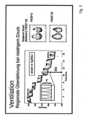
- FIG. 2 shows a schematic representation of the EIT measurement under ventilation.
- the ventilator also includes, for example, at least one additional sensor device 3 for carrying out the EIT measurement.
- the sensor device has, for example, 32 high-resolution sensors 3, 3'... in a textile belt, not shown.
- a not shown, integrated position sensor determines the position of the patient.
- the sensors are interconnected 4 by communication or line means 4 and arranged to receive signals sequentially from all directions.
- the control unit 21 can therefore spatially assign the sensor measurement values to the EIT measurement 3.
- the local tissue resistances can thus be determined from different directions and then converted into moving images.
- the control unit 21 processes the sensor measurement values of the EIT measurement 3 in such a way that a specific electrical impedance (EI) is determined for individual lung sections LA1, LA2.
- the sensor device 3 is connected to the control unit 21 via wired or wireless communication means 35 .
- the control unit 21 stores 11 and processes the sensor readings for use by the ventilator.
- the memory device 31 can be part of the control unit 21 or a separate module.
- the control unit 21 processes the sensor measurement values for use by the ventilator in such a way that, for example, a visualization of the patient's thorax P with the two lungs L is shown on the display of the ventilator 10 .
- the control unit 21 processes the sensor measurement values of the EIT measurement 3 in such a way that a specific electrical impedance (EI) of the lung L is determined for individual lung sections LA1, LA2.
- the specific electrical impedance (EI) of the lung sections LA is processed for display on the display in such a way that lung sections with a high electrical impedance L2 are represented graphically differently than those lung sections with a low electrical impedance L1.
- the control unit 21 temporally processes the sensor measurement values of the EIT measurement 3 in such a way that a specific electrical impedance EI of the lung L is determined for individual lung sections LA1, LA2 for each breath and is prepared for display on the display.
- the sensor device 3 (together with the controller and the memory) is also set up and designed to form, for example, an EIT sum signal 44', which is a measure of the ventilation of the lungs or lung sections.
- the sensor device 3 is also set up and configured (together with the controller and the memory) to determine a frequency of the EIT change frequency 44". The sensor device 3 can therefore determine the instantaneous ventilation 44 in summary.
- the EIT sum signal 44' is understood to mean that the impedance or impedance change distribution in the sectional plane determined by the sensors or the volume spanned by the sensors does not necessarily have to be shown graphically, for example on a display, for the implementation of the method, but at least the calculated result values of the impedance distribution or impedance change distribution (for the implementation of the method in the device according to the invention are available.
- the EIT change frequency 44" can be determined from the respiratory phase-dependent change in the impedance values of the sensors.
- the impedance values of the sensors fluctuate depending on the respiratory phase with inspiration and expiration.
- the EIT change frequency 44" therefore represents an alternative or supplementary measure by which the (frequency der) to determine ventilation of the lungs.
- the sensors are integrated into a textile, breathable and stretchable electrode belt together with a position sensor.
- the sensor 3 and the control unit are set up to generate an image rate of, for example, up to 50 per second. Lung areas LA are visualized.
- patient-related inputs are possible, such as body height, body weight, gender, chest circumference.
- the EIT data determined and processed in this way enable a differentiated analysis and representation of the electrical impedance EI of the lungs with temporal and spatial resolution.
- strain VT / FRC
- strain The calculation of the local strain (strain) of this novel EIT-based method (which as such does not fall under the claims) is carried out at the pixel level by determining the tidal volume of each pixel from its respective impedance change (delta Z) during the respiratory cycle and then inserting this into the in relation to its respective end-expiratory volume, which corresponds to its impedance value at the end of expiration (EELI).
- the pixel strain at each PEEP level was related to the individual pixel strain at the reference PEEP of 15 cmH2O, achieving a normalization that made it possible to create comparable relative strain images, which were the basis for the Calculation of numerical values of the total strain for the respective PEEP level.
- the respective pixel values were added up and normalized with regard to the number of all pixels in the lung ROI of each pig.
- EIT images were generated from the aforementioned strain images, which represented the mean relative strain of all subjects at the respective PEEP level.
- the measurement and control technology of the ventilator is networked with electrical impedance tomography (EIT).
- EIT electrical impedance tomography
Description
Die vorliegende Erfindung betrifft ein System zur Echtzeit-Bestimmung einer lokalen Beanspruchung einer Lunge während einer künstlichen Beatmung. Ferner betrifft die Erfindung ein System zur automatisierten Einstellung eines durch ein Beatmungsgerät vorgegebenen Wertes, insbesondere eines Drucks, vorzugsweise eines positiven endexspiratorischen Drucks (PEEP), umfassend ein vorgenanntes System zur Echtzeit-Bestimmung einer lokalen Beanspruchung einer Lunge während einer künstlichen Beatmung, sowie weiterhin ein Beatmungsgerät umfassend ein vorgenanntes System zur automatisierten Einstellung eines durch ein Beatmungsgerät vorgegebenen Wertes. Ein Verfahren zur Bestimmung einer lokalen Beanspruchung einer Lunge während einer künstlichen Beatmung, sowie ein Verfahren zur automatisierten Einstellung eines durch ein Beatmungsgerät vorgegebenen Wertes sind nicht erfindungsgemäß und dienen der Veranschaulichung. Weiterhin betrifft die Erfindung ein entsprechendes Beatmungsgerät.The present invention relates to a system for real-time determination of a local strain on a lung during artificial respiration. Furthermore, the invention relates to a system for the automated setting of a value specified by a ventilator, in particular a pressure, preferably a positive end-expiratory pressure (PEEP), comprising an aforementioned system for real-time determination of a local load on a lung during artificial ventilation, and also a Respirator comprising an aforesaid system for the automated setting of a value specified by a respirator. A method for determining local stress on a lung during artificial respiration and a method for automatically setting a value specified by a respirator are not in accordance with the invention and are used for illustration. Furthermore, the invention relates to a corresponding ventilator.
Bei maschineller Beatmung von Patienten mittels eines Beatmungsgerätes wird dem Patienten Atemgas mit Überdruck zugeführt. Deswegen ist bei der Beatmung der Atemwegsdruck bzw. alveoläre Druck zumindest während der Inspirationsphase größer als der Druck im die Lungenbläschen bzw. Alveolen umgebenden Pleuraspalt. Wird in der Exspirationsphase die Druckbeaufschlagung des Atemwegs durch die Beatmungseinrichtung wieder zurückgefahren, so hat dies die Folge, dass das Lungengewebe sich entspannt und der Atemwegsdruck bzw. der alveoläre Druck sinkt. Diese Art der Überdruckbeatmung kann unter bestimmten Umständen dazu führen, dass sich die Druckverhältnisse im Atemweg bzw. in den Alveolen am Ende der Exspirationsphase derart ungünstig einstellen, dass es zu einem Kollaps von Teilen der Alveolen kommt. Dann muss der kollabierte Teil des Lungenvolumens im nachfolgenden Atmungszyklus erst wieder entfaltet werden. Die funktionelle Residualkapazität der Lunge wird dadurch negativ beeinträchtigt, so dass die Sauerstoffsättigung abnimmt, und auch das Lungengewebe kann Schaden nehmen.In mechanical ventilation of patients by means of a ventilator, breathing gas is supplied to the patient at overpressure. Therefore, during ventilation, the airway pressure or alveolar pressure is greater than the pressure in the pleural space surrounding the alveoli or alveoli, at least during the inspiration phase. If the pressure applied to the airway by the ventilation device is reduced again in the expiration phase, this has the result that the lung tissue relaxes and the airway pressure or the alveolar pressure decreases. Under certain circumstances, this type of positive pressure ventilation can lead to the pressure conditions in the airway or in the alveoli at the end of the expiration phase being set so unfavorably that parts of the alveoli collapse. The collapsed part of the lung volume then has to be unfolded again in the subsequent breathing cycle. The functional residual capacity of the lungs is negatively affected, so that the oxygen saturation decreases, and the lung tissue can also be damaged.
Um einen Kollaps von Alveolen am Ende der Exspirationsphase vorzubeugen, wird bei der maschinellen Überdruckbeatmung regelmäßig ein sogenannter positiver end-exspiratorischer Druck - im Folgenden kurz PEEP genannt - eingestellt.In order to prevent the alveoli from collapsing at the end of the expiration phase, a so-called positive end-expiratory pressure - hereinafter referred to as PEEP - is regularly set during mechanical positive pressure ventilation.
Bei künstlicher Beatmung mit PEEP beaufschlagt die Beatmungseinrichtung den Atemweg dauerhaft - also sowohl während der Inspirationsphase als auch während der Exspirationsphase - mit zumindest einem vorbestimmten Überdruck, dem PEEP. Der PEEP liegt also nach dem Ende der Exspirationsphase noch an.In the case of artificial respiration with PEEP, the respiration device applies at least one predetermined overpressure, the PEEP, to the airway permanently—that is, both during the inspiration phase and during the expiration phase. The PEEP is therefore still present after the end of the expiratory phase.
Es gilt, den PEEP möglichst so einzustellen, dass während der Exspirationsphase der alveoläre Druck nicht, oder jedenfalls nur so weit, unterhalb des Druckes im Pleuraspalt liegt, dass das alveoläre Gewebe unter der Wirkung des Drucks im Pleuraspalt nicht kollabiert. Allerdings kann ein zu hoher Wert des PEEP negative Folgen haben, insbesondere während der Inspirationsphase. Denn das Lungengewebe kann bei sehr hohen Atemwegsdrücken während der Inspirationsphase überdehnt werden. Es kommt lokal zu einer zu großen Beanspruchung der Lunge.It is important to set the PEEP in such a way that during the expiration phase the alveolar pressure is not, or at least only so far below the pressure in the pleural space that the alveolar tissue does not collapse under the effect of the pressure in the pleural space. However, too high a PEEP value can have negative consequences, especially during the inspiration phase. Because the lung tissue can be overstretched at very high airway pressures during the inspiration phase. There is too much local strain on the lungs.
Es ist daher erstrebenswert, die Beanspruchung der Lunge möglichst genau beobachten zu können, um Rückschlüsse auf einen gegebenenfalls zu hoch oder zu niedrig eingestellten PEEP - bzw. andere die künstliche Beatmung charakterisierende Parameter - zu ziehen.It is therefore desirable to be able to observe the strain on the lungs as precisely as possible in order to draw conclusions about a PEEP which may have been set too high or too low - or other parameters characterizing artificial respiration.
Im Stand der Technik ist es üblich, die Belastung bzw. Beanspruchung der Lunge als sogenannten "strain" anzugeben, indem das Tidalvolumen auf die funktionale Residualkapazität der Lunge bezogen wird. Die Beanspruchung der Lunge ("strain"; STR) lässt sich somit über die folgende Gleichung bestimmen: ![]()
- STR:
- "strain" (Beanspruchung der Lunge)
- FRC:
- funktionale Residualkapazität
- STR:
- "strain" (strain on the lungs)
- FRC:
- functional residual capacity
Problematisch bei einer solchen Bestimmung der Beanspruchung der Lunge ist jedoch zum einen, dass die funktionale Residualkapazität nur schwer bestimmbar ist, in besonderem Maße während einer künstlichen Beatmung eines Patienten. Zum anderen liefert eine solche, oben genannte Bestimmung der Beanspruchung der Lunge nur einen globalen Wert für die Beanspruchung der Lunge. Es ist keine örtliche Auflösung dahingehend möglich, welche Bereiche der Lunge mehr und welche weniger belastet sind. Ein Rückschluss über lokal überdehnte Lungenbereiche oder lokal kollabierte Abschnitte der Lunge ist nicht möglich.However, the problem with such a determination of the load on the lungs is, on the one hand, that the functional residual capacity is difficult to determine, particularly during artificial respiration of a patient. On the other hand, such an above-mentioned determination of the strain on the lungs only provides a global value for the strain on the lungs. No local resolution is possible as to which areas of the lungs are more and which are less stressed. A conclusion about locally overstretched lung areas or locally collapsed sections of the lung is not possible.
An dieser Stelle kann die Elektro-Impedanz-Tomographie - im Folgenden kurz EIT genannt - Abhilfe leisten. EIT ist ein bildgebendes Verfahren, mittels welchem auf nicht-invasive Weise Rückschlüsse auf den Zustand der Lunge eines Patienten gezogen werden können. Hierzu wird ausgenutzt, dass die durch Atembewegungen des Patienten beeinflusste Änderung eines mittels EIT gewonnenen Impedanzsignals in Bereichen, in denen die Lunge noch nicht kollabiert ist, größer ist als in Bereichen mit kollabierten Alveolen.This is where electro-impedance tomography - hereinafter referred to as EIT - can help. EIT is an imaging technique that can be used to non-invasively draw conclusions about the condition of a patient's lungs. For this purpose, use is made of the fact that the change in an impedance signal obtained by means of EIT, which is influenced by the patient's breathing movements, is greater in areas in which the lung has not yet collapsed than in areas with collapsed alveoli.
Durch EIT steht ein Verfahren zur Verfügung, das erlaubt, in Echtzeit Information über den Zustand-der Lunge, insbesondere über das Öffnen und Schließenvon Alveolen oder eine Überdehnung von Alveolen, zu erhalten. Die EIT kann direkt am Bett des Patienten durchgeführt werden und liefert räumlich differenzierte Informationen hinsichtlich unterschiedlicher Bereiche der Lunge. Zu Details der EIT wird auch auf das Dokument
Es ist nun wünschenswert, dass auf möglichst einfache Art und Weise, Rückschlüsse auf die lokale Beanspruchung einer Lunge während einer künstlichen Beatmung geschlossen werden können, um idealerweise auch Handlungsweisungen auf die für die künstliche Beatmung einzustellenden Parameter abzuleiten.It is now desirable to be able to draw conclusions about the local stress on a lung during artificial respiration in the simplest possible way, in order ideally also to derive instructions for the parameters to be set for artificial respiration.
Demnach liegt der vorlegenden Erfindung die Aufgabe zugrunde, ein System zur Echtzeit-Bestimmung einer lokalen Beanspruchung einer Lunge während einer künstlichen Beatmung bereitzustellen, das auf nicht-invasive, schnelle und verlässliche Weise die lokale Beanspruchung der Lunge darstellen kann.Accordingly, the object of the present invention is to provide a system for real-time determination of a local load on a lung during artificial respiration, which system can display the local load on the lungs in a non-invasive, fast and reliable manner.
Eine weitere Aufgabe ist es, ein System zur automatisierten Einstellung eines durch ein Beatmungsgerät vorgegebenen Wertes bereitzustellen, das auf schnelle und verlässliche Weise die künstliche Beatmung der Lunge kontrollieren kann.A further object is to provide a system for the automated setting of a value specified by a ventilator, which can control the artificial ventilation of the lungs in a fast and reliable manner.
Eine weitere Aufgabe ist es, ein Beatmungsgerät bereitzustellen, das auf verlässliche Weise eine künstliche Beatmung der Lunge durchführen kann, wobei die Gefahr einer Überdehnung oder eines Kollapses von Bereichen der Lunge reduziert ist.A further object is to provide a ventilator which can reliably perform artificial ventilation of the lungs, reducing the risk of overexpansion or collapse of regions of the lungs.
Eine weitere Aufgabe ist es, ein Verfahren zur Bestimmung einer lokalen Beanspruchung einer Lunge während einer künstlichen Beatmung bereitzustellen, mittels dessen auf nicht-invasive, schnelle und verlässliche Weise die lokale Beanspruchung der Lunge bestimmt werden kann. Eine weitere Aufgabe ist es, ein Verfahren zur automatisierten Einstellung eines durch ein Beatmungsgerät vorgegebenen Wertes bereitzustellen, mittels dessen auf verlässliche Weise die künstliche Beatmung der Lunge kontrolliert werden kann.A further object is to provide a method for determining a local strain on a lung during artificial respiration, by means of which the local strain on the lungs can be determined in a non-invasive, rapid and reliable manner. A further object is to provide a method for the automated setting of a value specified by a ventilator, by means of which the artificial ventilation of the lungs can be controlled in a reliable manner.
Gelöst werden die genannten Aufgaben durch ein System zur Echtzeit-Bestimmung einer lokalen Beanspruchung einer Lunge während einer künstlichen Beatmung nach Anspruch 1, durch ein System zur automatisierten Einstellung eines durch ein Beatmungsgerät vorgegebenen Wertes nach Anspruch 4 sowie durch ein Beatmungsgerät nach Anspruch 5. Ein Verfahren zur Bestimmung einer lokalen Beanspruchung einer Lunge während einer künstlichen Beatmung, sowie ein Verfahren zur automatisierten Einstellung eines durch ein Beatmungsgerät vorgegebenen Wertes sind nicht erfindungsgemäß und dienen der Veranschaulichung.The stated objects are achieved by a system for real-time determination of a local strain on a lung during artificial respiration according to
Die Unteransprüche betreffen verschiedene voneinander unabhängige, vorteilhafte Weiterbildungen der vorliegenden Erfindung.The dependent claims relate to various advantageous developments of the present invention that are independent of one another.
Im Einzelnen wird nach einem ersten Aspekt der Erfindung ein System zur Echtzeit-Bestimmung einer lokalen Beanspruchung einer Lunge während einer künstlichen Beatmung vorgeschlagen. Das System umfasst ein Beatmungsgerät, wobei das Beatmungsgerät Teil des Systems ist; wobei eine Einrichtung zur Elektro-Impedanz-Tomographie (EIT) vorgesehen ist, die dazu eingerichtet ist, eine elektrische Impedanzverteilung entlang wenigstens eines zweidimensionalen Schnitts durch einen menschlichen Thorax zu erfassen; wobei eine Einrichtung zur Zuordnung der erfassten elektrischen Impedanzverteilung vorgesehen ist, die dazu eingerichtet ist, die erfasste elektrische Impedanzverteilung zu verschiedenen Zeitpunkten während der künstlichen Beatmung in eine Vielzahl von EIT-Pixeln zu unterteilen und einen spezifischen Wert der elektrischen Impedanz zu einem spezifischen Zeitpunkt einem spezifischen EIT-Pixel zuzuweisen, wobei eine Einrichtung zur Bestimmung eines lokalen Beanspruchungswertes vorgesehen ist, die dazu eingerichtet ist; zumindest eine end-inspiratorische elektrische Impedanz (ZINSP) des spezifischen EIT-Pixels sowie eine end-exspiratorische elektrische Impedanz (ZEXSP) des spezifischen EIT-Pixels zu bestimmen und einen lokalen Tidalvolumenreferenzwert (ΔZ) des spezifischen EIT-Pixels als Differenz aus der end-inspiratorischen elektrischen Impedanz (ZINSP) und der end-exspiratorischen elektrischen Impedanz (ZEXSP) durch Subtraktion der end-exspiratorischen elektrischen Impedanz (ZEXSP) von der end-inspiratorischen elektrischen Impedanz (ZINSP) zu bilden, dadurch gekennzeichnet, dass die Einrichtung dazu eingerichtet ist; einen vorläufigen Beanspruchungswert (STRVORL) des spezifischen EIT-Pixels durch Dividieren des lokalen Tidalvolumenreferenzwertes (ΔZ) durch die end-exspiratorische elektrische Impedanz (ZEXSP) zu bilden und einen relativen Beanspruchungswert (STRRELATIV) des spezifischen EIT-Pixels durch Normierung des vorläufigen Beanspruchungswert (STRVORL) auf einen Referenz-Beanspruchungswert (STRREF) zu bilden.In detail, according to a first aspect of the invention, a system for real-time determination of a local strain on a lung during artificial respiration is proposed. The system includes a ventilator, the ventilator being part of the system; wherein a device for electro-impedance tomography (EIT) is provided, which is set up to detect an electrical impedance distribution along at least one two-dimensional section through a human thorax; wherein a device for assigning the recorded electrical impedance distribution is provided, which is set up for this purpose is to subdivide the detected electrical impedance distribution into a plurality of EIT pixels at different points in time during the artificial respiration and to assign a specific value of the electrical impedance to a specific EIT pixel at a specific point in time, a device for determining a local strain value being provided , which is set up for this; to determine at least an end-inspiratory electrical impedance (ZINSP) of the specific EIT pixel and an end-expiratory electrical impedance (ZEXSP) of the specific EIT pixel and a local tidal volume reference value (ΔZ) of the specific EIT pixel as a difference from the end- inspiratory electrical impedance (ZINSP) and the end-expiratory electrical impedance (ZEXSP) by subtracting the end-expiratory electrical impedance (ZEXSP) from the end-inspiratory electrical impedance (ZINSP), characterized in that the device is set up; to form a preliminary stress value (STRVORL) of the specific EIT pixel by dividing the local tidal volume reference value (ΔZ) by the end-expiratory electrical impedance (ZEXSP) and to form a relative stress value (STRRELATIVE) of the specific EIT pixel by normalizing the preliminary stress value (STRVORL ) to form a reference stress value (STRREF).
Wesentlich an der vorliegenden Erfindung ist, dass mithilfe des beschriebenen Systems eine örtlich aufgelöste Beobachtung der Lunge hinsichtlich einer eventuellen Überdehnung vorgenommen werden. Diese Beobachtung kann darüber hinaus in Echtzeit während einer künstlichen Beatmung vorgenommen werden. Dies kann erfolgen, ohne dass aufwendige Eingriffe zu Lasten des Patienten erforderlich wären, da die EIT ein nicht-invasives, bildgebendes Verfahren ist.What is essential to the present invention is that the system described is used to perform a locally resolved observation of the lungs with regard to possible overexpansion. This observation can also be made in real time during artificial respiration. This can be done without the need for costly interventions at the expense of the patient, since EIT is a non-invasive, imaging procedure.
Dadurch dass die erfassten Impedanzwerte als Referenzwerte für ein in einem spezifischen EIT-Pixel vorhandenen Volumen dienen können, kann auf einzelne Bereiche der Lunge aufgelöst eine lokale Bestimmung eines analogen Wertes für das Tidalvolumen im spezifischen EIT-Pixel vorgenommen werden. Wenn dieser, das Tidalvolumen repräsentierende Referenz-Impedanzwert nun auf den Referenz-Impedanzwert, welcher das in demselben EIT-Pixel verbleibende Volumen repräsentiert, bezogen wird, kann ein Wert erreicht werden, welcher die Beanspruchung in diesem spezifischen Bereich der Lunge wiedergibt. So kann anstelle der globalen Bestimmung der Beanspruchung bzw. des "strain" gemäß Stand der Technik nun eine lokale Auflösung erreicht werden und die lokale Beanspruchung bzw. der lokale "strain" bestimmt werden.Since the impedance values recorded can be used as reference values for a volume present in a specific EIT pixel, a local determination of an analog value for the tidal volume in the specific EIT pixel can be undertaken for individual regions of the lung. If this reference impedance value representing the tidal volume is now related to the reference impedance value representing the volume remaining in the same EIT pixel, a value can be obtained which reflects the strain in this specific area of the lung. So instead of the global determination of the stress or the "strain" according to the prior art, a local resolution can be achieved and the local stress or the local "strain" can be determined.
Diese lokale Bestimmung erfolgt dementsprechend für ein spezifisches EIT-Pixel nach der folgenden Gleichung: ![]()
- STRVORL: vorläufiger Beanspruchungswert
- ΔZ: lokaler Tidalvolumenreferenzwert
- ZEXSP: end-exspiratorische elektrische Impedanz
- STR PREL : preliminary stress value
- ΔZ: local tidal volume reference value
- Z EXSP : end-expiratory electrical impedance
Zur Bestimmung des lokalen Tidalvolumenreferenzwertes (ΔZ) des spezifischen EIT-Pixels wird erfindungsgemäß eine Subtraktion der end-exspiratorischen elektrischen Impedanz (ZEXSP) von der end-inspiratorischen elektrischen Impedanz (ZINSP) vorgenommen werden.According to the invention, the end-expiratory electrical impedance (Z EXSP ) is subtracted from the end-inspiratory electrical impedance (Z INSP ) to determine the local tidal volume reference value (ΔZ) of the specific EIT pixel.
Mittels des vorliegenden Systems wird die end-inspiratorische elektrische Impedanz (ZINSP) sowie die end-exspiratorische elektrische Impedanz (ZEXSP) bestimmt. Daraus wird die Differenz als Repräsentant für das lokale Tidalvolumen in dem konkreten Lungenbereich bestimmt. Schließlich wird durch den Bezug dieser Referenz erneut auf die - das in dem konkreten Bereich verbleibende Volumen repräsentierende - end-exspiratorische elektrische Impedanz (ZEXSP) ein die Beanspruchung des Lungenbereichs repräsentierender Wert erreicht.The end-inspiratory electrical impedance (Z INSP ) and the end-expiratory electrical impedance (Z EXSP ) are determined using the present system. From this, the difference is determined as a representative for the local tidal volume in the specific lung area. Finally, by relating this reference again to the end-expiratory electrical impedance (Z EXSP ), which represents the volume remaining in the specific area, a value representing the stress on the lung area is achieved.
Die end-exspiratorische elektrische Impedanz (ZEXSP) entspricht dabei dem Endwert der elektrischen Impedanz zum Ende der Exspiration in dem spezifischen EIT-Pixel. Sie kann auch kurz EELI genannt werden.The end-expiratory electrical impedance (Z EXSP ) corresponds to the final value of the electrical impedance at the end of expiration in the specific EIT pixel. It can also be called EELI for short.
Dieser, die Beanspruchung des konkreten Lungenbereiches repräsentierende Wert wird vorliegend "vorläufiger Beanspruchungswert" genannt. Abschließend wird mittels des vorliegenden Systems dieser vorläufige Beanspruchungswert noch normiert. Eine solche Normierung meint, dass ein Quotient aus dem vorläufigen Beanspruchungswert und einem Referenz-Beanspruchungswert (STRREF) gebildet wird. Auf diese Weise wird schließlich ein relativer Beanspruchungswert erzielt, der die lokale Beanspruchung der Lunge repräsentiert.This value, which represents the stress on the specific area of the lungs, is referred to here as the "preliminary stress value". Finally, this provisional stress value is normalized using the present system. Such normalization means that a quotient is formed from the provisional stress value and a reference stress value (STR REF ). In this way, a relative stress value is finally obtained, which represents the local stress on the lungs.
Durch die Normierung wird eine Vergleichbarkeit erzielt, indem der spezifische, in Echtzeit bestimmte, vorläufige Beanspruchungswert noch auf einen Referenz-Beanspruchungswert bezogen wird, der den Zustand der "offenen Lunge" repräsentiert. Unter "offener Lunge" ist dabei gemeint, dass die Lunge weder kollabiert noch überdehnt ist. Es wird also der konkret bestimmte, vorläufige Beanspruchungswert dadurch normalisiert, dass er auf einen die Lunge repräsentierenden Wert in einem annähernden Normalzustand bezogen wird. Auf diese Weise wird ein relativer Beanspruchungswert erzielt, der die lokale Beanspruchung der Lunge repräsentiert.The standardization achieves comparability, in that the specific, provisional stress value determined in real time is still based on a reference stress value is obtained, which represents the condition of the "open lung". "Open lung" means that the lung is neither collapsed nor overstretched. The concretely determined, provisional stress value is therefore normalized by relating it to a value that represents the lungs in an approximately normal state. In this way, a relative stress value is obtained that represents the local stress on the lungs.
Nach einer ersten vorteilhaften Ausführungsform kann es sich bei dem Referenz-Beanspruchungswert (STRREF) um einen Quotienten aus dem lokalen Tidalvolumenreferenzwert (ΔZ) und der end-exspiratorischen elektrischen Impedanz (ZEXSP) des spezifischen EIT-Pixels bei einem vorgegebenen positiven endexspiratorischen Druck (PEEP) handeln. Dementsprechend kann die Einrichtung zur Bestimmung eines lokalen Beanspruchungswertes für die Bildung des relativen Beanspruchungswert (STRRELATIV) des spezifischen EIT-Pixels derart ausgebildet sein, dass der vorläufige Beanspruchungswert (STRVORL) auf einen Quotienten aus dem lokalen Tidalvolumenreferenzwert (ΔZ) und der end-exspiratorischen elektrischen Impedanz (ZEXSP) des spezifischen EIT-Pixels bei einem vorgegebenen positiven endexspiratorischen Druck (PEEP) normiert werden kann. Bei diesem vorgegebenen positiven endexspiratorischen Druck (PEEP) kann es sich um einen sogenannten "open lung PEEP" oder kurz "OL-PEEP" handeln. Bei diesein Wert für den vorgegebenen positiven endexspiratorischen Druck in Form eines "open lung PEEP" bzw. "OL-PEEP" kann ein end-exspiratorischer Kollaps der Lunge vermieden werden. Dieser Ausführungsform liegt also die Überlegung zugrunde, dass bei einer künstlichen Beatmung mit einem solchen vorgegebenen PEEP die Verhältnisse in der Lunge derart sind, dass die Gefahr eines Kollapses von Lungenbereichen aber auch einer Überdehnung von Lungenbereichen minimal ist. Durch die Normierung auf diesen sogenannten "Normalzustand" kann eine besonders gute Online-Beobachtung in Echtzeit der Belastung einzelner Lungenbereiche erzielt werden. Auf diese Weise kann der Einfluss des PEEP, oder auch anderer die künstliche Beatmung des Patienten steuernder Parameter, auf die lokale Belastung der Lunge beobachtet und demnach über die Steuerung der Parameter kontrolliert werden.According to a first advantageous embodiment, the reference stress value (STR REF ) can be a quotient of the local tidal volume reference value (ΔZ) and the end-expiratory electrical impedance (Z EXSP ) of the specific EIT pixel at a given positive end-expiratory pressure ( PEEP) act. Accordingly, the device for determining a local stress value for forming the relative stress value (STR RELATIVE ) of the specific EIT pixel can be designed in such a way that the preliminary stress value (STR VORL ) is based on a quotient of the local tidal volume reference value (ΔZ) and the final expiratory electrical impedance (Z EXSP ) of the specific EIT pixel at a given positive end-expiratory pressure (PEEP). This predefined positive end-expiratory pressure (PEEP) can be a so-called “open lung PEEP” or “OL-PEEP” for short. With this one value for the predetermined positive end-expiratory pressure in the form of an “open lung PEEP” or “OL-PEEP”, an end-expiratory collapse of the lung can be avoided. This embodiment is therefore based on the consideration that in the case of artificial respiration with such a predetermined PEEP, the conditions in the lungs are such that the risk of lung regions collapsing, but also of lung regions overexpanding, is minimal. By normalizing to this so-called "normal state", a particularly good online observation in real time of the load on individual lung areas can be achieved. In this way, the influence of the PEEP, or other parameters controlling the patient's artificial respiration, on the local load on the lungs can be observed and accordingly controlled by controlling the parameters.
Der relative Beanspruchungswert (STRRELATIV) eines spezifischen EIT-Pixels kann demnach über die folgende Gleichung bestimmt werden: 
- STRRELATIV:
- relativer Beanspruchungswert
- STRVORL:
- vorläufiger Beanspruchungswert
- ΔZOL-PEEP:
- Tidalvolumenreferenzwert bei OL-PEEP
- ZEXSP, OL-PEEP:
- end-exspiratorische elektrische Impedanz bei OL-PEEP
- ΔZ:
- lokaler Tidalvolumenreferenzwert
- ZEXSP:
- end-exspiratorische elektrische Impedanz
- STRRELATIVE:
- relative stress value
- STRIVE:
- preliminary stress value
- ΔZOL PEEP:
- Tidal volume reference value at OL-PEEP
- ZEXSP, OL-PEEP:
- end-expiratory electrical impedance in OL-PEEP
- ΔZ:
- local tidal volume reference
- ZEXSP:
- end-expiratory electrical impedance
Als Referenz für die beschriebene Normierung kann der Quotient aus lokalem Tidalvolumenreferenzwert (ΔZ) und der end-exspiratorischen elektrischen Impedanz (ZEXSP) beispielsweise bei einem positiven endexspiratorischen Druck in Höhe von 15 cmH2O verwendet werden. Alternativ kann auch ein anderer positiver endexspiratorischer Druck als Referenzwert dienen.The quotient of the local tidal volume reference value (ΔZ) and the end-expiratory electrical impedance (Z EXSP ) can be used as a reference for the normalization described, for example with a positive end-expiratory pressure of 15 cmH 2 O. Alternatively, another positive end-expiratory pressure can also serve as a reference value.
Dabei können verschiedene (als solche nicht unter die Ansprüche fallende) Verfahren angewandt werden, um vorab den "OL-PEEP" zu bestimmen und schließlich den zuvor beschriebenen Schritt der Normierung erfolgreich durchzuführen:
- So kann als "OL-PEEP" der Wert verwendet werden, bei dem der transmurale Druck größer als 0 ist.
- Auch kann als "OL-PEEP" der Wert verwendet werden, bei dem der Pesophagus-Druck größer als 0 ist.
- Auch kann mittels EIT ein "OL-PEEP" ermittelt werden, indem eine Druckrampe gefahren und der Druck bestimmt wird, bei dem sich in den abhängigen Lungenpixeln eine plötzliche Zunahme der Impedanz gibt. Dies deutet den Öffnungsdruck der Pixelregion an.
- Auch mittels der sogenannten "best dynamic compliance Technik" kann ein "OL-PEEP" ermittelt werden. Insofern wird auf das Paper von Suarez-Sipmann verwiesen (
Crit Care Med 2007 Vol. 35, No. 1, S. 214 - 221 - Auch mittels EIT gemäß Costa kann ein "OL-PEEP" bestimmt werden. Insofern wird auf das Paper von Cosat verwiesen (
Intensive Care Med; DOI 10.1007/s00134-009-1447-y - Durch direkte Messung des exspiratorischen Lungenvolumens, ist ebenfalls eine Ermittlung eines Referenzwertes zwecks Normierung auf ein annähernd normales Lungenvolumen (welches bei gesunder Lungen und einem PEEP in der Höhe von 0 der funktionalen Residualkapazität - FRC - entspricht) möglich.
- The value at which the transmural pressure is greater than 0 can be used as “OL-PEEP”.
- The value at which the esophagus pressure is greater than 0 can also be used as "OL-PEEP".
- "OL-PEEP" can also be determined using EIT by running a pressure ramp and determining the pressure at which there is a sudden increase in impedance in the dependent lung pixels. This indicates the opening pressure of the pixel region.
- An "OL-PEEP" can also be determined using the so-called "best dynamic compliance technique". In this respect, reference is made to the paper by Suarez-Sipmann (
Crit Care Med 2007 Vol. 35, No. 1, pp. 214 - 221 - An "OL-PEEP" can also be determined using EIT according to Costa. In this respect, reference is made to the paper by Cosat (
Intensive Care Med; DOI 10.1007/s00134-009-1447-y - By directly measuring the expiratory lung volume, it is also possible to determine a reference value for normalization to an almost normal lung volume (which corresponds to the functional residual capacity - FRC - in healthy lungs and a PEEP of 0).
Nach einem weiteren Aspekt der Lehre wird ein System zur automatisierten Einstellung eines durch ein Beatmungsgerät vorgegebenen Wertes, insbesondere eines Drucks, vorzugsweise eines positiven endexspiratorischen Drucks (PEEP), vorgeschlagen, umfassend ein vorbeschriebenes System, wobei eine Regelungseinrichtung vorgesehen ist, die dazu eingerichtet ist, den durch das Beatmungsgerät vorgegebenen Wert auf Grundlage der gebildeten relativen Beanspruchungswerte (STRRELATIV) anzupassen.According to a further aspect of the teaching, a system for the automated setting of a value specified by a ventilator, in particular a pressure, preferably a positive end-expiratory pressure (PEEP), is proposed, comprising an above-described system, a control device being provided which is set up to adjust the value given by the ventilator based on the formed relative stress values (STR RELATIVE ).
Nach einem weiteren Aspekt der Lehre wird ein Beatmungsgerät vorgeschlagen, umfassend ein solches System zur automatisierten Einstellung eines durch ein Beatmungsgerät vorgegebenen Wertes.According to a further aspect of the teaching, a ventilator is proposed, comprising such a system for the automated setting of a value specified by a ventilator.
Nach einem weiteren nicht unter die Ansprüche fallenden Aspekt der Lehre wird ein Beatmungsgerät zur Ausführung der Verfahren und/oder zur Verwendung in den Systemen vorgeschlagen.According to a further aspect of the teaching that does not fall under the claims, a ventilator for carrying out the methods and/or for use in the systems is proposed.
Beispielsweise ist die Erfindung auch dadurch gekennzeichnet, dass die Einrichtung zur Elektro-Impedanz-Tomographie (EIT) mit dem Beatmungsgerät gekoppelt ist oder Teil des Beatmungsgerätes ist.For example, the invention is also characterized in that the device for electro-impedance tomography (EIT) is coupled to the ventilator or is part of the ventilator.
Durch die Übertragung des zuvor beschriebenen Systems zur Echtzeit-Bestimmung einer lokalen Beanspruchung einer Lunge während einer künstlichen Beatmung beispielsweise auf ein Beatmungsgerät kann die künstliche Beatmung eines Patienten dahingehend verbessert werden, dass die gewonnenen Kenntnisse über die lokale Belastung einzelner Lungenareale dazu eingesetzt werden können, die Beatmungsparameter anzupassen. So kann beispielsweise der PEEP insbesondere dann angepasst werden, wenn festgestellt wird, dass einzelne Lungenareale einer zu hohen Beanspruchung ausgesetzt sind. Dies kann beispielsweise dadurch detektiert werden, dass der relative Beanspruchungswert hoch ist. Durch die Anpassung des PEEP (beispielsweise in Form einer Erhöhung oder Verringerung) oder auch durch die Anpassung anderer Beatmungsparameter kann in Echtzeit die Änderung des relative Beanspruchungswert (STRRELATIV) beobachtet werden. Ein anderer einzustellender Beatmungsparameter kann beispielsweise das Tidalvolumen sein. Denn, wenn das an dem Beatmungsgerät vorgesehene Tidalvolumen verringert wird, so wird dadurch auch in der Regel die Überdehnung bzw. der "strain" der Lunge verringert werden können. Es können auch Mittel, beispielsweise eine Regelungseinrichtung, vorgesehen sein, die den PEEP oder andere Werte wie das Tidalvolumen oder andere Werte automatisch anpassen, sodass jederzeit ein gewünschter, beispielsweise besonders geringer, relativer Beanspruchungswert (STRRELATIV) vorliegt.By transferring the system described above for real-time determination of a local load on a lung during artificial ventilation, for example on a ventilator, the artificial ventilation of a patient can be improved in that the knowledge gained about the local load on individual lung areas can be used to adjust ventilation parameters. For example, the PEEP can be adjusted in particular if it is determined that individual areas of the lung are exposed to excessive stress. This can be detected, for example, by the fact that the relative stress value is high. By adjusting the PEEP (e.g. in the form of an increase or decrease) or by adjusting other ventilation parameters, the change in the relative stress value (STR RELATIVE ) can be observed in real time. Another ventilation parameter to be set can be the tidal volume, for example. Because if that provided on the ventilator If the tidal volume is reduced, the overexpansion or "strain" of the lungs can usually be reduced. Means, for example a control device, can also be provided which automatically adjust the PEEP or other values such as the tidal volume or other values, so that a desired, for example particularly low, relative stress value (STR RELATIVE ) is present at all times.
Nach einem weiteren Aspekt der Lehre wird ein (nicht unter die Ansprüche fallendes) Verfahren zur Bestimmung einer lokalen Beanspruchung einer Lunge während einer künstlichen Beatmung vorgeschlagen, insbesondere zur Durchführung in einem System nach einem der Ansprüche 1 bis 2. Dabei werden die folgende Schritte ausgeführt: Erfassen einer elektrischen Impedanzverteilung entlang wenigstens eines zweidimensionalen Schnitts durch einen menschlichen Thorax mittels einer Einrichtung zur Elektro-Impedanz-Tomographie (EIT); Unterteilen der erfassten elektrischen Impedanzverteilung zu verschiedenen Zeitpunkten während der künstlichen Beatmung in eine Vielzahl von EIT-Pixeln; Zuweisen eines spezifischen Wertes der elektrischen Impedanz einem spezifischen EIT-Pixel zu einem spezifischen Zeitpunkt; Bestimmen zumindest einer end-inspiratorischen elektrischen Impedanz (ZINSP) des spezifischen EIT-Pixels sowie einer end-exspiratorischen elektrischen Impedanz (ZEXSP) des spezifischen EIT-Pixels; Bilden eines lokalen Tidalvolumenreferenzwertes (ΔZ) des spezifischen EIT-Pixels als Differenz aus der end-inspiratorischen elektrischen Impedanz (ZINSP) und der end-exspiratorischen elektrischen Impedanz (ZEXSP), insbesondere durch Subtraktion der end-exspiratorischen elektrischen Impedanz (ZEXSP) von der end-inspiratorischen elektrischen Impedanz (ZINSP); Bilden eines vorläufigen Beanspruchungswertes (STRVORL) des spezifischen EIT-Pixels durch Dividieren des lokalen Tidalvolumenreferenzwertes (ΔZ) durch die end-exspiratorische elektrische Impedanz (ZEXSP); und Bilden eines relativen Beanspruchungswertes (STRRELATIV) des spezifischen EIT-Pixels durch Normierung des vorläufigen Beanspruchungswert (STRVORL) auf einen Referenz-Beanspruchungswert (STRREF).According to a further aspect of the teaching, a method (not covered by the claims) for determining a local stress on a lung during artificial respiration is proposed, in particular for implementation in a system according to one of
Nach einer weiteren vorteilhaften Ausführungsform des (nicht unter die Ansprüche fallenden) Verfahrens wird der Referenz-Beanspruchungswert (STRREF) als Quotient aus dem lokalen Tidalvolumenreferenzwert (ΔZ) und der end-exspiratorischen elektrischen Impedanz (ZEXSP) des spezifischen EIT-Pixels bei einem vorgegebenen positiven endexspiratorischen Druck (PEEP) gebildet.According to a further advantageous embodiment of the method (not falling under the claims) the reference stress value (STR REF ) as a quotient of the local tidal volume reference value (ΔZ) and the end-expiratory electrical impedance (Z EXSP ) of the specific EIT pixel at a predetermined positive end-expiratory pressure (PEEP).
Die konkreten Auswirkungen und Vorteile dieser Verfahren sind zuvor bereits hinsichtlich des Systems zur Echtzeit-Bestimmung einer lokalen Beanspruchung einer Lunge während einer künstlichen Beatmung beschrieben worden. Insofern wird auf diese Bezug genommen.The concrete effects and advantages of these methods have already been described above with regard to the system for real-time determination of a local strain on a lung during artificial respiration. In this respect, reference is made to them.
Weiter vorzugsweise kann bei dem (nicht unter die Ansprüche fallenden) Verfahren zunächst ein relevantes Lungenareal identifiziert werden. Durch diesen Schritt kann die Effizienz des Verfahrens weiter erhöht werden. So kann durch einen vorgeschalteten Schritt genau der Bereich erfasst werden, bei welchem zu beobachtendes Lungengewebe bei dem Patienten vorliegt. Die EIT kann dementsprechend optimiert werden, da die impedanzmessungen nur hinsichtlich der Areale von Bedeutung sind, in denen auch wirklich Lungengewebe vorhanden ist.More preferably, in the method (not covered by the claims) a relevant lung area can first be identified. This step can further increase the efficiency of the method. In this way, the area in which the lung tissue to be observed is present in the patient can be precisely recorded by means of a preceding step. The EIT can be optimized accordingly, since the impedance measurements are only of importance with regard to the areas in which lung tissue is actually present.
Dazu können beispielsweise zunächst Referenz-Impedanzmessungen vorgenommen werden. So kann beispielsweis die elektrische Impedanz bei einer künstlichen Beatmung unter erhöhtem PEEP bestimmt werden. Bei einem erhöhtem PEEP wird nämlich davon ausgegangen, dass auch unter Umständen kollabiertes Lungengewebe sich erneut mit Luft füllt und entfaltet und dementsprechend auch einen Ausschlag bei der Impedanzmessung zeigt. Alle Bereiche, die bei einer Impedanzmessung unter erhöhtem PEEP demnach eine signifikante, beispielsweise über einem vorgegebenen Schwellenwert liegende, Impedanzdifferenz (etwa in Form der lokalen Tidalvolumenreferenzwertes ΔZ) zeigen, können somit als relevantes Lungenareal identifiziert werden.For this purpose, for example, reference impedance measurements can first be carried out. For example, the electrical impedance can be determined during artificial respiration under increased PEEP. In the case of an increased PEEP, it is assumed that lung tissue that may have collapsed fills with air again and unfolds, and accordingly also shows a deflection in the impedance measurement. All areas that show a significant impedance difference (for example in the form of the local tidal volume reference value ΔZ) in an impedance measurement under increased PEEP, for example above a predetermined threshold value, can thus be identified as a relevant lung area.
Besonders bevorzugt können zur Identifizierung des relevanten Lungenareals auch mehrere Messungen bei verschiedenen PEEP-Werten vorgenommen werden und jeweils bei den unterschiedlichen Messungen die Pixel, welche eine vorhin genannte, signifikante Impedanzdifferenz zeigen, als relevantes Lungenareal gekennzeichnet werden. Denn gerade bei einem niedrigem PEEP kann es zwar zur Belüftung zuvor überdehnter Lungenbläschen, vor allem in den Schwerkraft-unabhängigen oberen Lungenpartien, kommen, während jedoch die zuunterst liegenden Lungenareale weiterhin kollabieren. Diese zuunterst liegenden Lungenareale zeigen beispielsweise erst bei einem höheren PEEP eine Ventilation, die sich in einer relevanten signifikanten Impedanzdifferenz äußert. Demnach sollte eine Vielzahl verschiedener PEEP Werte bei der Identifizierung des relevanten Lungenareals eingestellt werden und die Pixel als Lungenpixel identifiziert werden, die auf wenigstens einer der PEEP-Stufen tidale Ventilation zeigen.In order to identify the relevant lung area, a number of measurements can particularly preferably be carried out at different PEEP values and the pixels which show a previously mentioned significant impedance difference can be marked as relevant lung area in the different measurements. Especially with a low PEEP, previously overstretched air sacs can be ventilated, especially in the upper parts of the lungs, which are independent of gravity, while the lowermost lung areas continue to collapse. These lowermost lung areas, for example, only show ventilation at a higher PEEP, which is expressed in a relevant, significant impedance difference. Accordingly, a variety of different PEEP values should be set when identifying the relevant lung area and those pixels should be identified as lung pixels that show tidal ventilation on at least one of the PEEP levels.
Bei den zuvor beschriebenen Systemen kann dementsprechend auch eine Einrichtung zur Identifizierung eines relevanten Lungenareals vorgesehen sein, die dazu eingerichtet ist, ein relevantes Lungenareal zu identifizieren.Accordingly, in the systems described above, a device for identifying a relevant area of the lungs can also be provided, which is set up to identify a relevant area of the lungs.
Schließlich wird nach einem weiteren Aspekt der Lehre ein (nicht unter die Ansprüche fallendes) Verfahren zur automatisierten Einstellung eines durch ein Beatmungsgerät vorgegebenen Wertes, insbesondere eines Drucks, vorzugsweise eines positiven endexspiratorischen Drucks (PEEP), vorgeschlagen, wobei die folgenden Schritte ausgeführt werden: Bestimmen einer lokalen Beanspruchung einer Lunge während einer künstlichen Beatmung mittels eines Verfahrens zur Bestimmung einer lokalen Beanspruchung einer Lunge während einer künstlichen Beatmung nach einem der Ansprüche 5 bis 7; und Anpassen des durch das Beatmungsgerät vorgegebenen Wertes auf Grundlage der gebildeten relativen Beanspruchungswerte (STRRELATIV).Finally, according to a further aspect of the teaching, a method (not covered by the claims) for the automated setting of a value specified by a ventilator, in particular a pressure, preferably a positive end-expiratory pressure (PEEP), is proposed, the following steps being carried out: determining a local strain on a lung during artificial respiration by means of a method for determining a local strain on a lung during artificial respiration according to any one of claims 5 to 7; and adjusting the ventilator commanded value based on the established relative stress values (STR RELATIVE ).
Die konkreten Auswirkungen und Vorteile dieses Verfahrens sind zuvor bereits hinsichtlich des Systems zur automatisierten Einstellung eines durch ein Beatmungsgerät vorgegebenen Wertes beschrieben worden. Insofern wird auf diese Bezug genommen.The specific effects and advantages of this method have already been described above with regard to the system for the automated setting of a value specified by a ventilator. In this respect, reference is made to them.
Insbesondere kann der zuvor beschriebene Wert in Form des relativen Beanspruchungswertes (STRRELATIV) dazu genutzt werden, dass die Parameter für die künstliche Beatmung dahingehend angepasst werden, bis sich bei einer zu hohen Beanspruchung bzw. "strain", sprich bei einem erhöhten relativen Beanspruchungswert (STRRELAIIV), (erneut) ein gewünschter niedriger Wert einstellt. So kann durch das vorgeschlagene Verfahren auf zuverlässige Weise sichergestellt_werden, dass eine Überdehnung, jedoch ebenso ein Kollaps, einzelner Lungenbereiche vermieden wird. Beispielsweise kann der PEEP reduziert werden, falls ein zu hoher, über einem Schwellenwert liegender Wert als relativer Beanspruchungswert gemessen wird. Wesentlich ist dabei jedoch auch, dass bei lediglich geringem eingestellten PEEP bei künstlicher Beatmung ebenfalls eine Überdehnung bzw. der "strain" sicher detektiert werden können. Durch die vorliegende Erfindung ist es auch möglich, die Überdehnung bzw. den "Strain" für die Gesamtlunge in Werten auszudrücken. Dazu kann als Grundlage die Gesamtheit aller Pixelwerte des Lungenareals dienen. So kann der mittlere Überdehnungswert bzw. der mittlere "Strain" aller Pixel im Lungenareal bestimmt werden, indem die "Strain-Werte" aller Pixel aufsummiert werden und diese Summe durch die Anzahl der Pixel im Lungenareal geteilt wird. So können anhand eines einfachen numerischen Wertes verschiedene Beatmungseinstellungen objektiv miteinander verglichen werden. So kann der PEEP oder aber das Tidalvolumen auf Grundlage dieses einfachen Wertes gezielt eingestellt werden.In particular, the previously described value in the form of the relative stress value (STR RELATIVE ) can be used to adapt the parameters for artificial respiration until the stress or "strain", i.e. an increased relative stress value ( STR RELAIIV ), (again) sets a desired low value. The proposed method can thus ensure in a reliable manner that overexpansion, but also collapse, of individual lung areas is avoided. For example, PEEP can be reduced if the measured relative stress value is too high, above a threshold value. However, it is also important that with only a low PEEP setting in the case of artificial respiration, an overexpansion or the "strain" can also be reliably detected. The present invention also makes it possible to express the overstretching or the "strain" for the entire lung in values. The total of all pixel values of the lung area can serve as a basis for this. In this way, the average overstretching value or the average "Strain" of all pixels in the lung area can be determined by summing up the "strain values" of all pixels and dividing this sum by the number of pixels in the lung area. In this way, different ventilation settings can be compared objectively using a simple numerical value. In this way, the PEEP or the tidal volume can be specifically set on the basis of this simple value.
Mit der vorliegenden Erfindung kann vorteilhaft das Problem der Identifikation von Lungenbelastungen bei einem niedrigem PEEP gelöst werden. Sobald die Lunge zusammenfällt, wird das verbleibende restliche Lungengewebe reaktiv überdehnt. Je größer der Anteil des Kollapses ist, desto mehr Überdehnung findet statt. Genau diese Überdehnung kann durch die vorliegende Erfindung sichtbar gemacht werden. Der Nutzer des Systems kann animiert werden, als Reaktion mehr PEEP zu applizieren, um das für die Ventilation zur Verfügung stehende Lungenvolumen (EELI) zu erhöhen.With the present invention, the problem of identifying lung stresses when the PEEP is low can be advantageously solved. Once the lung collapses, the remaining residual lung tissue is reactively overstretched. The greater the proportion of collapse, the more overstretching takes place. Exactly this overstretching can be made visible by the present invention. The user of the system can be encouraged to apply more PEEP in response to increase the lung volume available for ventilation (EELI).
In der
Das Beatmungsgerät 1 ist beispielsweise Teil eines Systems 10 welches eine EIT-Vorrichtung 3 umfasst.The
Das Beatmungsgerät 1 umfasst wenigstens eine steuerbare Atemgasquelle 100 und eine programmierbare Steuereinrichtung 21 (Regeleinrichtung) und zumindest eine Sensoreinrichtung 2 zur Bestimmung von Druck und/oder Fluss des Atemgases, wobei die Steuereinrichtung 21 die Atemgasquelle zur Vorgabe eines ersten vorbestimmten Beatmungsmusters 45 (hinsichtlich Druck, Fluss, Volumen, Frequenz) ansteuert. Das Beatmungsgerät umfasst zudem wenigstens zwei weitere beispielsweise räumlich von dem Beatmungsgerät 1 getrennte Sensoreinrichtungen 3, 30, 40, die mit der Steuereinrichtung 21 des Beatmungsgerätes 1 kommunizieren. Ein Sensor 3 ist als EIT (oder EI)-Vorrichtung ausgebildet und weist eine Vielzahl einzelner Sensoreinrichtungen 3, 3', 3" ... auf und jede Sensoreinrichtung ist zur Erzeugung von elektrischen Potenzialen und/oder zur nichtinvasiven Bestimmung der elektrischen Impedanz (EI) eines Körperabschnitts und zur Ermittlung und Übertragung der Sensormesswerte an die Steuereinheit ausgebildet. Die Steuereinrichtung 21 wertet die Sensormesswerte der EI-Sensoreinrichtung 3 aus, zur Bestimmung der momentanen Ventilation 44 oder des "strain" (Beanspruchung) der Lunge während der Beatmung mit einem ersten Beatmungsmuster 45. Die Steuereinrichtung 21 steuert die Atemgasquelle beispielsweise auch zur Vorgabe eines zweiten Beatmungsmusters 55 an, welches hinsichtlich Druck und/oder Fluss und/oder Volumen und/oder Frequenz von dem ersten Beatmungsmuster 45 verschieden ist, wobei die Steuereinrichtung 21 die Sensormesswerte der EI-Sensoreinrichtung 3 auswertet zur Bestimmung der resultierenden Ventilation 54 oder des "strain" der Lunge während der Beatmung mit dem zweiten Beatmungsmuster 55, wobei die Steuereinrichtung 21 die momentanen Ventilation 44 oder den "strain" mit der resultierenden Ventilation 54 oder dem resultierenden "strain" vergleicht zur Feststellung des besser geeigneten Beatmungsmusters. Beispielsweise passt die Steuereinrichtung zumindest einen Druck beispielsweise den PEEP oder ein Beatmungsmuster so an, dass der "strain" reduziert wird.The
Beispielsweise wird der "strain" durch eine Erhöhung des EPAP oder des PEEP reduziert.For example, the "strain" is reduced by increasing the EPAP or the PEEP.
Das Beatmungsgerät 1 umfasst eine Atemgasquelle 100 mit beispielsweise einer Gebläseeinrichtung und/oder einer Ventileinrichtung 101 zur Erzeugung eines Atemgasstromes für die Beatmung: Zur Steuerung der Atemgasquelle 100 und zur Erfassung und Verarbeitung von Sensordaten ist hier eine Steuereinrichtung 21 vorgesehen. Die Bedienung und Einstellung des Beatmungsgerätes 1 erfolgt über eine Benutzerschnittstelle 61 mit Bedienelementen und einer Anzeigeeinrichtung 11 (Display).The
Das Beatmungsgerät 1 weist eine Atemschnittstelle 102 auf, um den Atemgasstrom einem Patienten zur Beatmung zuzuführen. Die hier gezeigte Atemschnittstelle 102 ist eine beispielhaft als Nasalmaske oder Vollmaske ausgebildete Atemmaske 105 oder ein Tubus. Zur Fixierung der Atemmaske 105 ist beispielsweise eine Kopfhaube 106 vorgesehen. Die Atemschnittstelle 102 kann beispielsweise auch als eine Vollgesichtsmaske, als eine Nasenbrille, als ein Tubus oder als eine Larynxmaske ausgestaltet sein.The
Zur Verbindung der Atemschnittstelle 102 mit der Atemgasquelle 100 ist zumindest ein Verbindungsschlauch 109 vorgesehen, der über eine Koppeleinrichtung 112 luftführend mit der Atemgasquelle 100 verbunden wird. Über ein Kuppelungselement 107 wird der Verbindungsschlauch 109 mit der Atemschnittstelle 102 verbunden. Zwischen dem Verbindungsschlauch 109 und dem Kuppelungselement 107 ist ein Ausatmungselement 108 angeordnet, welches ein Ventil umfasst oder als ein solches ausgebildet ist. Das Ausatmungselement 108 ist beispielsweise dazu vorgesehen, während der Ausatmung des Benutzers ein Rückatmen in das Beatmungsgerät 1 zu verhindern.At least one connecting
Die Steuereinrichtung 21 ist mit einer nicht näher dargestellten Sensoreinrichtung 2,3,30,40) verbunden, welche einen oder mehrere Sensoren zur Erfassung von Geräteparametern und/oder Patientenparametern und/oder anderer für die Beatmung charakteristischer Grö-ßen aufweist. Die Steuereinrichtung 21 kann als eine zentrale Steuereinrichtung, beispielsweise im dem Beatmungsgerät, ausgeführt sein, die alle Sensorwerte verarbeitet. Die Steuereinrichtung 21 kann in Form mehrerer dezentraler Steuereinrichtungen, beispielsweise eine im dem Beatmungsgerät und (je) eine, die einem (oder den) Sensor(en) zugeordnet ist, ausgeführt sein. für die Beatmung charakteristischer Größen aufweist.The
Zum Beispiel umfasst die Steuereinrichtung 21 einen hier nicht näher gezeigten Drucksensor 2 welcher die Druckverhältnisse des Atemgases ermittelt. Dazu ist der Drucksensor, beispielsweise über einen Druckmessschlauch 110 zu der Atemschnittstelle 102, mit dem Atemgas wirkverbunden. Über einen Eingangsstutzen 111 ist der Druckmessschlauch 110 an die Steuereinrichtung 21 angebunden. Zum Beispiel umfasst die Steuereinrichtung 21 auch einen hier nicht näher gezeigten Flusssensor 2, welcher die Flussverhältnisse des Atemgases ermittelt. Des Weiteren dient die Steuereinrichtung 21 hier zur Ansteuerung der Gebläseeinrichtung und/oder der Ventileinrichtung 101. Die Steuereinrichtung 21 stellt einen notwendigen Minimaldruck bereit und kompensiert Druckschwankungen, die durch die Atemtätigkeit des Benutzers bedingt sind. Beispielsweise erfasst die Steuereinrichtung 21 auch den gegenwärtigen Druck in der Atemmaske 105 und regelt die Leistung der Atemgasquelle entsprechend nach, bis ein gewünschter Beatmungsdruck anliegt.For example, the
Die zur Einstellung der Atemgasquelle 100 benötigten Geräteparameter sowie die Gerätekonfiguration und/oder Gerätesoftware sind in einer Speichereinrichtung 31 hinterlegt.The device parameters required for setting the
Die Steuereinrichtung 21 kann auch den Sauerstoffgehalt im Atemgas regeln, durch entsprechende Ansteuerung der Gebläseeinrichtung und/oder der Ventileinrichtung 101, wobei die Ventileinrichtung zumindest eine Sauerstoffquelle (Druckgasflasche oder Krankenhausleitung) aufweist oder konnektiert. Die Sauerstoffzumischung zu dem Atemgasstrom erfolgt beispielsweise stromabwärts oder stromaufwärts von der Gebläseeinrichtung. In diesem Fall ist die Ventileinrichtung ein Sauerstoffmischventil. Die Sauerstoffzumischung zu dem Atemgasstrom erfolgt beispielsweise durch eine Ventileinheit, die den Atemgasstrom und den Sauerstoffstrom führt und regelt.The
Die Steuereinrichtung 21 kann auch zur Erfassung von sensorisch erfassten Patientenparametern ausgebildet sein. Die Steuereinrichtung 21 kann dazu mit Sensoren zur Messung der Atemexkursion, zur Messung einer Sauerstoffversorgung und/oder einer Kohlendioxidversorgung und /oder zur Messung einer EEG-, einer EMG-, einer EOG- oder einer EKG-Aktivität ausgestattet sein.The
Das System 10 weist insbesondere wenigstens zwei räumlich von dem Beatmungsgerät 1 getrennte, Sensoreinrichtungen 3,30,40 auf, die mit der Steuereinheit 21 kommunizieren, wobei ein Sensor 3 eine Vielzahl einzelner Sensoreinrichtungen 3, 3', 3" ... aufweist und jede Sensoreinrichtung zur Erzeugung von elektrischen Potenzialen ausgebildet ist 13 zur nichtinvasiven Bestimmung der elektrischen Impedanz EI eines Körperabschnitts. Die Sensoreinrichtungen 3 sind beispielsweise als Klebepflaster ausgeführt, mit einer der Haut abgewandten Au-ßenschicht und einer der Haut zugewandten adhäsiven Schicht, oder als Gurt zusammengefasst, der die Sensoreinrichtungen haltert.In particular, the
Das Beatmungsgerät umfasst beispielhaft auch zumindest eine weitere Sensoreinrichtung 30, die zur nichtinvasiven Bestimmung eines Kohlenstoffdioxid (CO2)-Wertes 30 ausgebildet ist. Die Sensoreinrichtung 30 ist beispielsweise als Klemmsensor oder als Klebepflaster ausgeführt mit einer der Haut abgewandten Außenschicht und einer der Haut zugewandten adhäsiven Schicht. Die Beatmungsvorrichtung 10 umfasst zumindest eine weitere Sensoreinrichtung 40, die zur nichtinvasiven Bestimmung eines Sauerstoff (O2)-Wertes 40 ausgebildet ist. Die Sensoreinrichtung 30 ist beispielsweise als Klemmsensor oder als Klebepflaster ausgeführt mit einer der Haut abgewandten Außenschicht und einer der Haut zugewandten adhäsiven Schicht. Der (CO2)-Werte 30 und/oder der (O2)-Werte (40 können erfindungsgemäß invasiv oder nicht-invasiv im Gewebe des Patienten bestimmt werden und/oder nicht-invasiv im Atemgasstrom.By way of example, the ventilator also includes at least one
Die Sensoren 3,30,40 umfassen beispielsweise Energie- und Sendemittelmittel zur Ermittlung und kabellosen Übertragung der Sensormesswerte. Die Sensoren 3,30,40 umfassen alternativ beispielsweise Kommunikationsmittel 35, 45 zur Übertragung der Sensormesswerte an die Steuerung 21.The
Das Beatmungsgerät umfasst beispielhaft auch zumindest eine weitere Sensoreinrichtung 3 zur Durchführung der EIT-Messung.The ventilator also includes, for example, at least one
Die Sensoreinrichtung weist beispielsweise 32 hochauflösende Sensoren 3,3'... in einem textilen Gürtel, nicht dargestellt, auf. Ein, nicht dargestellter, integrierter Lagesensor bestimmt die Position des Patienten. Die Sensoren sind durch Kommunikations- oder Leitungsmittel 4 miteinander verbunden 4 und so angeordnet, dass sie Signale nacheinander aus allen Richtungen empfangen können. Die Steuereinheit 21 kann die Sensormesswerte der EIT-Messung 3 daher räumlich zuordnen.. Damit können die lokalen Gewebswiderstände aus unterschiedlichen Richtungen ermittelt und dann in bewegte Bilder umgerechnet werden. Die Steuereinheit 21 verarbeitet die Sensormesswerte der EIT-Messung 3 derart, dass für einzelne Lungenabschnitte LA1, LA2 eine spezifische elektrische Impedanz (EI) ermittelt wird. Die Sensoreinrichtung 3 ist über kabelgebundene oder drahtlose Kommunikationsmittel 35 mit der Steuereinheit 21 verbunden. Die Steuereinheit 21 speichert 11 und verarbeitet die Sensormesswerte zur Verwendung durch das Beatmungsgerät. Der Speichereinrichtung 31 kann Bestandteil der Steuereinheit 21 sein oder ein separater Baustein.The sensor device has, for example, 32 high-
Die Sensoreinrichtung 3 ist (zusammen mit der Steuerung und dem Speicher) auch eingerichtet und ausgebildet, beispielsweise ein EIT-Summensignal 44' zu bilden, welches ein Maß für die Ventilation der Lunge bzw. von Lungenabschnitten ist. Die Sensoreinrichtung 3 ist auch (zusammen mit der Steuerung und dem Speicher) eingerichtet und ausgebildet, eine Häufigkeit der EIT-Änderungsfrequenz 44" zu ermitteln. Die Sensoreinrichtung 3 kann somit zusammenfassend die momentane Ventilation 44 ermitteln.The sensor device 3 (together with the controller and the memory) is also set up and designed to form, for example, an EIT sum signal 44', which is a measure of the ventilation of the lungs or lung sections. The
Im Sinne der Erfindung wird unter dem EIT-Summensignal 44' verstanden, dass die Impedanz- oder Impedanzänderungsverteilung in der durch die Sensoren bestimmten Schnittebene oder dem durch die Sensoren umspannten Volumen nicht zwingend für die Durchführung des Verfahrens bildlich beispielsweise auf einem Display dargestellt werden muss, zumindest aber die berechneten Ergebniswerte der Impedanzverteilung oder Impedanzänderungsverteilung (für die Durchführung des Verfahrens in der erfindungsgemäßen Vorrichtung vorliegen.For the purposes of the invention, the EIT sum signal 44' is understood to mean that the impedance or impedance change distribution in the sectional plane determined by the sensors or the volume spanned by the sensors does not necessarily have to be shown graphically, for example on a display, for the implementation of the method, but at least the calculated result values of the impedance distribution or impedance change distribution (for the implementation of the method in the device according to the invention are available.
Bei einer Summation sämtlicher Impedanzwerte der Sensoren ergibt sich demnach bei der Inspiration ein geändertes Summensignal im Vergleich zu dem Summensignal bei der Exspiration. Der Summenwert stellt demnach ein adäquates Maß dar, um die Ventilation der Lunge zu bestimmen.When all the impedance values of the sensors are summed up, a changed sum signal results during inspiration compared to the sum signal during expiration. The total value therefore represents an adequate measure to determine the ventilation of the lungs.
Die EIT-Änderungsfrequenz 44" lässt sich aus der atemphasenabhängigen Änderung der Impedanzwerte der Sensoren bestimmen. Die Impedanzwerte der Sensoren schwanken atemphasenabhängig mit der Inspiration und der Exspiration. Die EIT-Änderungsfrequenz 44" stellt demnach ein alternatives oder ergänzendes Maß dar, um die (Frequenz der) Ventilation der Lunge zu bestimmen.The EIT change frequency 44" can be determined from the respiratory phase-dependent change in the impedance values of the sensors. The impedance values of the sensors fluctuate depending on the respiratory phase with inspiration and expiration. The EIT change frequency 44" therefore represents an alternative or supplementary measure by which the (frequency der) to determine ventilation of the lungs.
Beispielsweise sind die Sensoren in einen textilen und atmungsaktiven und dehnbaren Elektrodengürtel, zusammen mit einem Lagesensor, integriert. Der Sensor 3 und die Steuereinheit sind eingerichtet eine Bildrate von beispielsweise bis zu 50 pro Sekunde zu erzeugen. Dabei werden Lungenbereiche LA visualisiert. Erfindungsgemäß sind patientenbezogene Eingaben möglich, wie Körpergröße, Körpergewicht, Geschlecht, Brustkorbumfang.For example, the sensors are integrated into a textile, breathable and stretchable electrode belt together with a position sensor. The
Die so ermittelten und aufbereiteten EIT-Daten ermöglichen eine zeitlich und räumlich aufgelöste differenzierte Analyse und Darstellung der elektrischen Impedanz EI der Lunge.The EIT data determined and processed in this way enable a differentiated analysis and representation of the electrical impedance EI of the lungs with temporal and spatial resolution.
Alle Berechnungen wurden innerhalb der individuellen Lungen Region of Interest (ROI) durchgeführt, die gebildet wurde von den Pixeln, deren Amplitude mehr als x% der Amplitude des Pixels mit der maximalen atembedingten Impedanzänderung bei PEEP 30 betrug. Erfindungsgemäß kann die Beanspruchung (strain) der gesamten Lungen, die die atemzugsbedingte Verformung des Lungengewebes hervorruft, wie folgt abgeschätzt werden: ![]()
![]()
Die Berechnung der lokalen Beanspruchung (strain) dieser neuartigen EIT-basierten Methode (welche als solche nicht unter die Ansprüche fällt) erfolgt auf Pixelebene, indem das Tidalvolumen eines jeden Pixels aus seiner jeweiligen Impedanzänderung (delta Z) während des Atemzyklus bestimmt und dieses sodann ins Verhältnis zu seinem jeweiligen end-exspiratorischen Volumen, das seinem impedanzwert zum Ende der Exspiration (EELI) entspricht, gesetzt wurde. Die entsprechende Formel lautet daher: ![]()
![]()
Anschließend wurde der Pixel-strain auf jeder PEEP-Stufe ins Verhältnis gesetzt zum individuellen Pixel-strain beim Referenz-PEEP von 15 cmH2O, wodurch eine Normierung erzielt wurde, die es ermöglichte, vergleichbare relative strain-Bilder zu erstellen, die die Grundlage für die Berechnung numerischer Werte des totalen strains für die jeweilige PEEP-Stufe bildete. Hierzu wurden die jeweiligen Pixelwerte aufsummiert und bezüglich der Anzahl aller Pixel in der Lungen ROI eines jeden Schweines normiert. Schließlich wurden aus den zuvor genannten strain-Bildern EIT-Bilder generiert, die den mittleren relativen strain aller Probanden auf dem jeweiligen PEEP-Niveau repräsentierten.Subsequently, the pixel strain at each PEEP level was related to the individual pixel strain at the reference PEEP of 15 cmH2O, achieving a normalization that made it possible to create comparable relative strain images, which were the basis for the Calculation of numerical values of the total strain for the respective PEEP level. For this purpose, the respective pixel values were added up and normalized with regard to the number of all pixels in the lung ROI of each pig. Finally, EIT images were generated from the aforementioned strain images, which represented the mean relative strain of all subjects at the respective PEEP level.
Erfindungsgemäß wird die Mess- und Regelungstechnik des Beatmungsgerätes mit der Elektrischen Impedanz Tomographie EIT) vernetzt. Dadurch kann die Funktion der Lunge kontinuierlich bildgebend dargestellt werden. Die Messwerte des Beatmungsgerätes werden mit den Ergebnissen der elektrischen Impedanztomographie kombiniert. So ermöglicht es diese Technologie, die vielfältigsten klinischen Fragestellungen zu bewerten und die Therapie entspre-chend auszurichten.According to the invention, the measurement and control technology of the ventilator is networked with electrical impedance tomography (EIT). This allows the function of the lungs to be displayed continuously in imaging. The readings from the ventilator are combined with the results of electrical impedance tomography. This technology makes it possible to evaluate a wide range of clinical issues and to adjust therapy accordingly.
Claims (9)
- A system (10) for real-time determination of a local strain of a lung during artificial ventilation (1) using a ventilator, wherein the ventilator is part of the system (10), wherein the system (10) comprises a device for electrical impedance tomography (EIT) (3), which device is configured to capture an electrical impedance distribution along at least one two-dimensional section through a human thorax, and further comprises a device for assigning (33) the captured electrical impedance distribution, which device is configured to divide the captured electrical impedance distribution at different times during the artificial ventilation into a multiplicity of EIT pixels and to assign a specific value of the electrical impedance at a specific time to a specific EIT pixel, wherein the system further comprises a device for determining a local strain value (333), which device is configured to determine at least one end-inspiratory electrical impedance (ZINSP) of the specific EIT pixel and one end-expiratory electrical impedance (ZEXSP) of the specific EIT pixel and to form a local tidal volume reference value (ΔZ) of the specific EIT pixel as a difference between the end-inspiratory electrical impedance (ZINSP) and the end-expiratory electrical impedance (ZEXSP) by subtracting the end-expiratory electrical impedance (ZEXSP) from the end-inspiratory electrical impedance (ZINSP), characterized in that the device for determining a local strain value (333) is configured to form a preliminary strain value (STRVORL) of the specific EIT pixel by dividing the local tidal volume reference value (ΔZ) by the end-expiratory electrical impedance (ZEXSP) and to form a relative strain value (STRRELATIV) of the specific EIT pixel by normalizing the preliminary strain value (STRVORL) to a reference strain value (STRREF).
- The system of at least one of the preceding claims, characterized in that the device is configured to normalize the preliminary strain value (STRVORL) to a quotient of the local tidal volume reference value (ΔZ) and the end-expiratory electrical impedance (ZEXSP) of the specific EIT pixel at a specified positive end-expiratory pressure (PEEP).
- The system of at least one of the preceding claims, characterized in that the system comprises a device for electrical impedance tomography (EIT), which device is configured to capture an electrical impedance distribution along at least one two-dimensional section through a human thorax, and further comprises a device for assigning the captured electrical impedance distribution, which device is configured to divide the captured electrical impedance distribution at different times during the artificial ventilation into a multiplicity of EIT pixels and to assign a specific value of the electrical impedance at a specific time to a specific EIT pixel;wherein the system further comprises a device for determining a local strain value, which device is configuredto determine at least one end-inspiratory electrical impedance (ZINSP) of the specific EIT pixel and an end-expiratory electrical impedance (ZEXSP) of the specific EIT pixel,to form a local tidal volume reference value (ΔZ) of the specific EIT pixel as a difference between the end-inspiratory electrical impedance (ZINSP) and the end-expiratory electrical impedance (ZEXSP), in particular by subtracting the end-expiratory electrical impedance (ZEXSP) from the end-inspiratory electrical impedance (ZINSP), andto form a preliminary strain value (STRVORL) of the specific EIT pixel by dividing the local tidal volume reference value (ΔZ) by the end-expiratory electrical impedance (ZEXSP);and wherein the device for determining a local strain value is further configured to form a relative strain value (STRRELATIV) of the specific EIT pixel by normalizing the preliminary strain value (STRVORL) to a reference strain value (STRREF).
- A system for automatically setting a value specified by a ventilator, in particular of a pressure, preferably of a positive end-expiratory pressure (PEEP), wherein the system comprises a system of one of the preceding claims and a closed-loop control device that is configured to adapt the value specified by the ventilator on the basis of the relative strain values (STRRELATIV) formed.
- A ventilator configured and embodied for use in a system of at least one of claims 1 to 4, wherein the ventilator comprises a control device (21), wherein the ventilator comprises at least one controllable respiratory gas source (100) and at least one sensor device (2) for determining pressure and/or flow of the respiratory gas, wherein the control device (21) drives the respiratory gas source for specifying a first predetermined ventilation pattern (45), wherein the ventilator further comprises at least two further sensor devices (3, 30, 40) that communicate with the control device (21) of the ventilator (1), wherein the device for electrical impedance tomography (EIT) (3) is configured to capture an electrical impedance distribution along at least one two-dimensional section through a human thorax, wherein the control device (21) is configured to evaluate the sensor measured values of the device for electrical impedance tomography (EIT) (3), wherein the ventilator comprises a device for assigning (33) the captured electrical impedance distribution, which device is configured to divide the captured electrical impedance distribution at different times during the artificial ventilation into a multiplicity of EIT pixels and to assign a specific value of the electrical impedance at a specific time to a specific EIT pixel, wherein the ventilator comprises a device for determining a local strain value (333), which device is configured to determine at least one end-inspiratory electrical impedance (ZINSP) of the specific EIT pixel and one end-expiratory electrical impedance (ZEXSP) of the specific EIT pixel and to form a local tidal volume reference value (ΔZ) of the specific EIT pixel as a difference between the end-inspiratory electrical impedance (ZINSP) and the end-expiratory electrical impedance (ZEXSP) by subtracting the end-expiratory electrical impedance (ZEXSP) from the end-inspiratory electrical impedance (ZINSP), characterized in that the device for determining a local strain value (333) is configured to form a preliminary strain value (STRVORL) of the specific EIT pixel by dividing the local tidal volume reference value (ΔZ) by the end-expiratory electrical impedance (ZEXSP) and to form a relative strain value (STRRELATIV) of the specific EIT pixel by normalizing the preliminary strain value (STRVORL) to a reference strain value (STRREF).
- The ventilator (1) of claim 5, wherein the ventilator is configured and embodied to perform the global strain of the lungs, which causes the respiration-dependent deformation of the lung tissue, using the EIT information at a pixel level.
- The ventilator (1) of at least one of the preceding claims, wherein the ventilator is configured and embodied to perform a determination of the local strain of the lung using the EIT information at a pixel level, by virtue of the tidal volume of each pixel being determined from its respective change in impedance (delta Z) during the respiratory cycle and said tidal volume thereupon being related to its respective end-expiratory volume, which corresponds to its impedance value at the end of expiration (EELI).
- The ventilator (1) of at least one of the preceding claims, wherein the sensor device is configured to generate electrical potentials and/or to non-invasively determine the electrical impedance (El) of a body section and to determine and transfer the sensor measured values to the control unit, wherein the control device (21) evaluates the sensor measured values of the EI sensor device (3) for the purposes of determining the current (44) strain of the lung during the ventilation with a first ventilation pattern (45) and wherein the control device (21) drives the respiratory gas source for specifying a second ventilation pattern (55), which differs from the first ventilation pattern (45) in terms of pressure and/or flow and/or volume and/or frequency, wherein the control device (21) evaluates the sensor measured values of the EI sensor device (3) for the purposes of determining a resultant (54) strain of the lung during the ventilation with the second ventilation pattern (55).
- The ventilator (1) of at least one of the preceding claims, wherein the control device adapts at least one pressure, for example, the PEEP, or a ventilation pattern in such a way that the strain is reduced.
Applications Claiming Priority (1)
| Application Number | Priority Date | Filing Date | Title |
|---|---|---|---|
| DE102019109932 | 2019-04-15 |
Publications (2)
| Publication Number | Publication Date |
|---|---|
| EP3725222A1 EP3725222A1 (en) | 2020-10-21 |
| EP3725222B1 true EP3725222B1 (en) | 2023-07-12 |
Family
ID=70285372
Family Applications (1)
| Application Number | Title | Priority Date | Filing Date |
|---|---|---|---|
| EP20000151.9A Active EP3725222B1 (en) | 2019-04-15 | 2020-04-14 | System and ventilator for real-time determination of local stress of a lung during artificial respiration |
Country Status (4)
| Country | Link |
|---|---|
| US (1) | US11696699B2 (en) |
| EP (1) | EP3725222B1 (en) |
| CN (1) | CN111821549A (en) |
| DE (1) | DE102020002279A1 (en) |
Families Citing this family (6)
| Publication number | Priority date | Publication date | Assignee | Title |
|---|---|---|---|---|
| EP4011424A1 (en) * | 2020-12-07 | 2022-06-15 | Löwenstein Medical Technology S.A. | System for ventilating organisms |
| EP4059416A1 (en) * | 2021-03-18 | 2022-09-21 | SenTec AG | Regional strain |
| IT202100010775A1 (en) * | 2021-04-28 | 2022-10-28 | Roni Shabat | SYSTEMS AND METHODS FOR THE DETERMINATION OF LUNG IMPEDANCE |
| CN114024522B (en) * | 2021-12-20 | 2023-02-17 | 广州国家实验室 | Resistor network, device and method for simulating lung respiration |
| WO2024003413A1 (en) * | 2022-07-01 | 2024-01-04 | Academisch Ziekenhuis Maastricht | Method for controlling spontaneously triggered mechanical ventilation of a patient |
| CN116803342B (en) * | 2023-07-20 | 2024-03-29 | 中国人民解放军空军军医大学 | Impedance data processing method for anti-load training and related training system |
Family Cites Families (6)
| Publication number | Priority date | Publication date | Assignee | Title |
|---|---|---|---|---|
| DE102005022896B3 (en) | 2005-05-18 | 2006-05-11 | Dräger Medical AG & Co. KG | Method for controlling respirator involves receiving measuring signals with the help of electrical impedance measuring instrument fitted with electrode application at test person |
| BR102012028367B1 (en) * | 2012-11-06 | 2022-03-22 | Timpel S.A | Method and apparatus for generating and displaying a simplified representation of information obtained through electrical impedance tomography |
| DE102013203177A1 (en) | 2013-02-26 | 2014-08-28 | Hamilton Medical Ag | System for the automated setting of a predetermined by a ventilator pressure |
| DE102015006902B3 (en) | 2015-06-04 | 2016-06-30 | Drägerwerk AG & Co. KGaA | Device for processing and visualizing data from an electro-impedance tomography device for the detection and visualization of regional delays in ventilation in the lungs |
| DE102017007224A1 (en) * | 2017-08-02 | 2019-02-07 | Drägerwerk AG & Co. KGaA | Apparatus and method for determining difference ratios based on EIT data |
| DE102021000312A1 (en) * | 2020-02-07 | 2021-08-12 | Löwenstein Medical Technology S.A. | Method and device for determining a regional compliance of a lung during spontaneous breathing |
-
2020
- 2020-04-11 DE DE102020002279.0A patent/DE102020002279A1/en active Pending
- 2020-04-14 US US16/847,752 patent/US11696699B2/en active Active
- 2020-04-14 EP EP20000151.9A patent/EP3725222B1/en active Active
- 2020-04-15 CN CN202010296977.8A patent/CN111821549A/en active Pending
Also Published As
| Publication number | Publication date |
|---|---|
| US20200324067A1 (en) | 2020-10-15 |
| CN111821549A (en) | 2020-10-27 |
| DE102020002279A1 (en) | 2020-10-15 |
| EP3725222A1 (en) | 2020-10-21 |
| US11696699B2 (en) | 2023-07-11 |
Similar Documents
| Publication | Publication Date | Title |
|---|---|---|
| EP3725222B1 (en) | System and ventilator for real-time determination of local stress of a lung during artificial respiration | |
| EP2961315B2 (en) | System for automated adjustment of a pressure specified by a breathing device | |
| DE102007062214C5 (en) | Method for automatically controlling a respiratory system and associated ventilator | |
| DE69736808T2 (en) | DETERMINATION OF LEAKAGE FLOW | |
| EP1226841B1 (en) | Method and device for sleep monitoring | |
| DE69922511T2 (en) | RESPIRATORY SUPPORT SYSTEM WITH DETECTION OF BREATHING, INCORPORATING NEUROELECTRIC SIGNALS | |
| EP1148907B1 (en) | Non-invasive method for optimizing the respiration of atelectatic lungs | |
| DE102006018198A1 (en) | Method and device for lung ventilation | |
| DE112004001957T5 (en) | System and procedure for diaphragmatic stimulation | |
| EP3653248A2 (en) | Respirators and control methods for respirators | |
| DE102016011161A1 (en) | Device for processing and visualizing data of an electro-impedance tomography device for the determination and visualization of regional characteristics of the ventilation of the lungs | |
| EP3861932A1 (en) | Method and device for determining regional compliance of a lung in spontaneous breathing | |
| WO2009129641A1 (en) | Apparatus for assessing the stress on the circulation of a person during assisted breathing by means of a respirator | |
| WO2021063601A1 (en) | Method and device for determining a respiratory and/or cardiogenic signal | |
| EP3698713B1 (en) | System for detecting a patient's respiratory effort | |
| DE102015014106A1 (en) | Device for pressure-assisted or pressure-controlled ventilation of a patient with limited spontaneous breathing | |
| EP3957241B1 (en) | Assembly and computer program product for determining regional lung compliance | |
| DE102021000313A1 (en) | Method for operating a ventilator for artificial ventilation of a patient and such a ventilator | |
| EP3964253B1 (en) | Computer program and device for automatically determining the target frequency of a breathing apparatus | |
| DE102015011390A1 (en) | Apparatus, method and computer program for ventilating a patient | |
| DE102007052472A1 (en) | Method for operating a ventilation and / or anesthesia device in APRV mode taking into account the impedance and / or the impedance change | |
| DE102020001440A1 (en) | Ventilation device | |
| EP3524305A1 (en) | Artificial respiration device and control and test method | |
| CH719307A2 (en) | Method and system with a measuring device and an analysis device for processing data. | |
| AT515126B1 (en) | Measuring and control device for a ventilator |
Legal Events
| Date | Code | Title | Description |
|---|---|---|---|
| PUAI | Public reference made under article 153(3) epc to a published international application that has entered the european phase |
Free format text: ORIGINAL CODE: 0009012 |
|
| STAA | Information on the status of an ep patent application or granted ep patent |
Free format text: STATUS: THE APPLICATION HAS BEEN PUBLISHED |
|
| AK | Designated contracting states |
Kind code of ref document: A1 Designated state(s): AL AT BE BG CH CY CZ DE DK EE ES FI FR GB GR HR HU IE IS IT LI LT LU LV MC MK MT NL NO PL PT RO RS SE SI SK SM TR |
|
| AX | Request for extension of the european patent |
Extension state: BA ME |
|
| STAA | Information on the status of an ep patent application or granted ep patent |
Free format text: STATUS: REQUEST FOR EXAMINATION WAS MADE |
|
| 17P | Request for examination filed |
Effective date: 20210414 |
|
| RBV | Designated contracting states (corrected) |
Designated state(s): AL AT BE BG CH CY CZ DE DK EE ES FI FR GB GR HR HU IE IS IT LI LT LU LV MC MK MT NL NO PL PT RO RS SE SI SK SM TR |
|
| STAA | Information on the status of an ep patent application or granted ep patent |
Free format text: STATUS: EXAMINATION IS IN PROGRESS |
|
| 17Q | First examination report despatched |
Effective date: 20211011 |
|
| 17Q | First examination report despatched |
Effective date: 20211022 |
|
| REG | Reference to a national code |
Ref country code: DE Ref legal event code: R079 Ref document number: 502020004078 Country of ref document: DE Free format text: PREVIOUS MAIN CLASS: A61B0005053000 Ipc: A61B0005053600 Ref country code: DE Ref legal event code: R079 Free format text: PREVIOUS MAIN CLASS: A61B0005053000 Ipc: A61B0005053600 |
|
| GRAP | Despatch of communication of intention to grant a patent |
Free format text: ORIGINAL CODE: EPIDOSNIGR1 |
|
| STAA | Information on the status of an ep patent application or granted ep patent |
Free format text: STATUS: GRANT OF PATENT IS INTENDED |
|
| RIC1 | Information provided on ipc code assigned before grant |
Ipc: A61B 5/08 19680901ALI20230109BHEP Ipc: A61B 5/085 19900101ALI20230109BHEP Ipc: A61B 5/00 19680901ALI20230109BHEP Ipc: A61M 16/00 19680901ALI20230109BHEP Ipc: A61B 5/0536 20210101AFI20230109BHEP |
|
| INTG | Intention to grant announced |
Effective date: 20230131 |
|
| GRAS | Grant fee paid |
Free format text: ORIGINAL CODE: EPIDOSNIGR3 |
|
| GRAA | (expected) grant |
Free format text: ORIGINAL CODE: 0009210 |
|
| STAA | Information on the status of an ep patent application or granted ep patent |
Free format text: STATUS: THE PATENT HAS BEEN GRANTED |
|
| P01 | Opt-out of the competence of the unified patent court (upc) registered |
Effective date: 20230523 |
|
| AK | Designated contracting states |
Kind code of ref document: B1 Designated state(s): AL AT BE BG CH CY CZ DE DK EE ES FI FR GB GR HR HU IE IS IT LI LT LU LV MC MK MT NL NO PL PT RO RS SE SI SK SM TR |
|
| REG | Reference to a national code |
Ref country code: CH Ref legal event code: EP |
|
| REG | Reference to a national code |
Ref country code: IE Ref legal event code: FG4D Free format text: LANGUAGE OF EP DOCUMENT: GERMAN |
|
| REG | Reference to a national code |
Ref country code: DE Ref legal event code: R096 Ref document number: 502020004078 Country of ref document: DE |
|
| REG | Reference to a national code |
Ref country code: NL Ref legal event code: FP |
|
| REG | Reference to a national code |
Ref country code: LT Ref legal event code: MG9D |
|
| PG25 | Lapsed in a contracting state [announced via postgrant information from national office to epo] |
Ref country code: GR Free format text: LAPSE BECAUSE OF FAILURE TO SUBMIT A TRANSLATION OF THE DESCRIPTION OR TO PAY THE FEE WITHIN THE PRESCRIBED TIME-LIMIT Effective date: 20231013 |
|
| PG25 | Lapsed in a contracting state [announced via postgrant information from national office to epo] |
Ref country code: ES Free format text: LAPSE BECAUSE OF FAILURE TO SUBMIT A TRANSLATION OF THE DESCRIPTION OR TO PAY THE FEE WITHIN THE PRESCRIBED TIME-LIMIT Effective date: 20230712 |
|
| PG25 | Lapsed in a contracting state [announced via postgrant information from national office to epo] |
Ref country code: IS Free format text: LAPSE BECAUSE OF FAILURE TO SUBMIT A TRANSLATION OF THE DESCRIPTION OR TO PAY THE FEE WITHIN THE PRESCRIBED TIME-LIMIT Effective date: 20231112 |
|
| PG25 | Lapsed in a contracting state [announced via postgrant information from national office to epo] |
Ref country code: SE Free format text: LAPSE BECAUSE OF FAILURE TO SUBMIT A TRANSLATION OF THE DESCRIPTION OR TO PAY THE FEE WITHIN THE PRESCRIBED TIME-LIMIT Effective date: 20230712 Ref country code: RS Free format text: LAPSE BECAUSE OF FAILURE TO SUBMIT A TRANSLATION OF THE DESCRIPTION OR TO PAY THE FEE WITHIN THE PRESCRIBED TIME-LIMIT Effective date: 20230712 Ref country code: PT Free format text: LAPSE BECAUSE OF FAILURE TO SUBMIT A TRANSLATION OF THE DESCRIPTION OR TO PAY THE FEE WITHIN THE PRESCRIBED TIME-LIMIT Effective date: 20231113 Ref country code: NO Free format text: LAPSE BECAUSE OF FAILURE TO SUBMIT A TRANSLATION OF THE DESCRIPTION OR TO PAY THE FEE WITHIN THE PRESCRIBED TIME-LIMIT Effective date: 20231012 Ref country code: LV Free format text: LAPSE BECAUSE OF FAILURE TO SUBMIT A TRANSLATION OF THE DESCRIPTION OR TO PAY THE FEE WITHIN THE PRESCRIBED TIME-LIMIT Effective date: 20230712 Ref country code: LT Free format text: LAPSE BECAUSE OF FAILURE TO SUBMIT A TRANSLATION OF THE DESCRIPTION OR TO PAY THE FEE WITHIN THE PRESCRIBED TIME-LIMIT Effective date: 20230712 Ref country code: IS Free format text: LAPSE BECAUSE OF FAILURE TO SUBMIT A TRANSLATION OF THE DESCRIPTION OR TO PAY THE FEE WITHIN THE PRESCRIBED TIME-LIMIT Effective date: 20231112 Ref country code: HR Free format text: LAPSE BECAUSE OF FAILURE TO SUBMIT A TRANSLATION OF THE DESCRIPTION OR TO PAY THE FEE WITHIN THE PRESCRIBED TIME-LIMIT Effective date: 20230712 Ref country code: GR Free format text: LAPSE BECAUSE OF FAILURE TO SUBMIT A TRANSLATION OF THE DESCRIPTION OR TO PAY THE FEE WITHIN THE PRESCRIBED TIME-LIMIT Effective date: 20231013 Ref country code: FI Free format text: LAPSE BECAUSE OF FAILURE TO SUBMIT A TRANSLATION OF THE DESCRIPTION OR TO PAY THE FEE WITHIN THE PRESCRIBED TIME-LIMIT Effective date: 20230712 Ref country code: ES Free format text: LAPSE BECAUSE OF FAILURE TO SUBMIT A TRANSLATION OF THE DESCRIPTION OR TO PAY THE FEE WITHIN THE PRESCRIBED TIME-LIMIT Effective date: 20230712 |
|
| PG25 | Lapsed in a contracting state [announced via postgrant information from national office to epo] |
Ref country code: PL Free format text: LAPSE BECAUSE OF FAILURE TO SUBMIT A TRANSLATION OF THE DESCRIPTION OR TO PAY THE FEE WITHIN THE PRESCRIBED TIME-LIMIT Effective date: 20230712 |