EP3725176B1 - Tensioning systems for footwear - Google Patents
Tensioning systems for footwear Download PDFInfo
- Publication number
- EP3725176B1 EP3725176B1 EP20173088.4A EP20173088A EP3725176B1 EP 3725176 B1 EP3725176 B1 EP 3725176B1 EP 20173088 A EP20173088 A EP 20173088A EP 3725176 B1 EP3725176 B1 EP 3725176B1
- Authority
- EP
- European Patent Office
- Prior art keywords
- cable
- item
- shell
- boot
- tension
- Prior art date
- Legal status (The legal status is an assumption and is not a legal conclusion. Google has not performed a legal analysis and makes no representation as to the accuracy of the status listed.)
- Active
Links
Images





Classifications
-
- A—HUMAN NECESSITIES
- A43—FOOTWEAR
- A43B—CHARACTERISTIC FEATURES OF FOOTWEAR; PARTS OF FOOTWEAR
- A43B5/00—Footwear for sporting purposes
- A43B5/04—Ski or like boots
-
- A—HUMAN NECESSITIES
- A43—FOOTWEAR
- A43B—CHARACTERISTIC FEATURES OF FOOTWEAR; PARTS OF FOOTWEAR
- A43B5/00—Footwear for sporting purposes
- A43B5/002—Mountain boots or shoes
-
- A—HUMAN NECESSITIES
- A43—FOOTWEAR
- A43B—CHARACTERISTIC FEATURES OF FOOTWEAR; PARTS OF FOOTWEAR
- A43B5/00—Footwear for sporting purposes
- A43B5/04—Ski or like boots
- A43B5/0401—Snowboard boots
-
- A—HUMAN NECESSITIES
- A43—FOOTWEAR
- A43B—CHARACTERISTIC FEATURES OF FOOTWEAR; PARTS OF FOOTWEAR
- A43B5/00—Footwear for sporting purposes
- A43B5/04—Ski or like boots
- A43B5/0405—Linings, paddings or insertions; Inner boots
-
- A—HUMAN NECESSITIES
- A43—FOOTWEAR
- A43B—CHARACTERISTIC FEATURES OF FOOTWEAR; PARTS OF FOOTWEAR
- A43B5/00—Footwear for sporting purposes
- A43B5/04—Ski or like boots
- A43B5/0427—Ski or like boots characterised by type or construction details
-
- A—HUMAN NECESSITIES
- A43—FOOTWEAR
- A43B—CHARACTERISTIC FEATURES OF FOOTWEAR; PARTS OF FOOTWEAR
- A43B5/00—Footwear for sporting purposes
- A43B5/04—Ski or like boots
- A43B5/0427—Ski or like boots characterised by type or construction details
- A43B5/0435—Adjustment of the boot to the foot
- A43B5/0443—Adjustment of the boot to the foot to the instep of the foot, e.g. metatarsals; Metatarsal clamping devices
- A43B5/0447—Adjustment of the boot to the foot to the instep of the foot, e.g. metatarsals; Metatarsal clamping devices actuated by flexible means, e.g. cables, straps
-
- A—HUMAN NECESSITIES
- A43—FOOTWEAR
- A43B—CHARACTERISTIC FEATURES OF FOOTWEAR; PARTS OF FOOTWEAR
- A43B5/00—Footwear for sporting purposes
- A43B5/04—Ski or like boots
- A43B5/0427—Ski or like boots characterised by type or construction details
- A43B5/0476—Front-entry skiboots
-
- A—HUMAN NECESSITIES
- A43—FOOTWEAR
- A43B—CHARACTERISTIC FEATURES OF FOOTWEAR; PARTS OF FOOTWEAR
- A43B5/00—Footwear for sporting purposes
- A43B5/16—Skating boots
-
- A—HUMAN NECESSITIES
- A43—FOOTWEAR
- A43C—FASTENINGS OR ATTACHMENTS OF FOOTWEAR; LACES IN GENERAL
- A43C1/00—Shoe lacing fastenings
- A43C1/003—Zone lacing, i.e. whereby different zones of the footwear have different lacing tightening degrees, using one or a plurality of laces
-
- A—HUMAN NECESSITIES
- A43—FOOTWEAR
- A43C—FASTENINGS OR ATTACHMENTS OF FOOTWEAR; LACES IN GENERAL
- A43C11/00—Other fastenings specially adapted for shoes
- A43C11/16—Fastenings secured by wire, bolts, or the like
- A43C11/165—Fastenings secured by wire, bolts, or the like characterised by a spool, reel or pulley for winding up cables, laces or straps by rotation
-
- A—HUMAN NECESSITIES
- A43—FOOTWEAR
- A43C—FASTENINGS OR ATTACHMENTS OF FOOTWEAR; LACES IN GENERAL
- A43C11/00—Other fastenings specially adapted for shoes
- A43C11/20—Fastenings with tightening devices mounted on the tongue
Definitions
- the inventive subject matter in its various possible embodiments is directed to systems that tension an item of footwear to the foot and/or leg of a user so that the foot or leg is secured within the item during use.
- the inventive subject matter is particularly suitable for use in boots for snow and skating sports or any other such sport where sliding movement of the foot or leg relative to the item of footwear is undesirable and where secure coupling of the item to the foot and leg facilitates transfer of power to a board, ski, skate blade, set of skate wheels, etc., that is coupled to the item.
- the inventive subject matter is particularly, but not exclusively, directed to a tensioning system for a snowboard boot that tightens the boot parts around the user's instep or other anatomical areas, retracting the foot into the footbed and simultaneously retracting the heel into the heel area.
- the system provides a tension path that achieves the foregoing results and routes one or more cables to a tensioning mechanism that can be operated by the user to adjustably increase or decrease cable tension.
- Inventive subject matter disclosed herein overcomes one or more disadvantages of the prior art and provides various improvements.
- the present invention is defined by an item of footwear according to the appended claim 1.
- Preferred embodiments are defined by the appended dependent claims.
- the item of footwear may be a boot for a snow or skating sport.
- the closure elements may be adapted to receive laces or other cables.
- a liner in the nature of a removable bootie may be disposed in the shell.
- the closure mechanism may include a wheel or knob operable by a user to tension the cable.
- FIG. 5A through 9 Representative embodiments incorporating one or more aspects of the inventive subject matter are shown in Figs. 5A through 9 , wherein the same or generally similar features share common reference numerals.
- an item of footwear is configured with a foot retraction system for closing around the foot and retracting a portion of the footwear against a user's foot into the footbed and heel area of the item.
- disclosed innovations generally pertain to systems for tensioning a boot to the foot of a user so that the foot is retracted as so.
- the inventive subject matter is particularly useful with snowboarding boots. It can also be used with a variety of other kinds of boots, including ski boots, skate boots, hiking boots, and any other kind of footwear where it is desirable to engage an item footwear around the foot and keep the foot from lifting or sliding in the item of footwear.
- a snowboard boot 10 typically has an outer shell 12.
- the shell is typically a semi-rigid structure made of an assembly of materials, such as one or more of sheets or layers of natural or synthetic leathers, woven or non-woven textiles, and plastics and rubbers. Some or all of the shell may be made of molded plastics or rubbers.
- the boot includes a tongue 14. The tongue is part of the shell
- the boot may have an inner liner 16, which is usually a removable bootie but it can also be built into the shell 12.
- a footbed for receiving the bottom of the user's foot is part of the boot, and may be formed in the liner material or it may be a separate structure.
- the boot also includes a heel cup for wrapping around and receiving the heel of a user. It is typically formed in the liner. In the representative embodiment shown in the Figures, opposing edges of shell 12 are spaced apart and in-filled by tongue 14.
- the outer shell includes an upper portion 12a that extends upward from the instep, over the ankle, and around a lower leg portion of a user.
- the shell also includes a proximal foot enclosure portion 12b, enclosing the general areas of the instep and heel and a distal portion 12c for enclosing the top and sides of the midfoot and forefoot.
- the boot includes a sole 18 that connects to shell 12 and covers the bottom of the user's foot.
- the outer shell 12 in a snowboard boot is made up of relatively stiff and rugged materials, such as leathers and semi-rigid or rigid plastics, rubbers, or other such materials.
- the shell may include an inner liner that is typically made up of a thickened set of materials that provide cushioning, comfort, and insulation to a user's foot.
- the liner may be made of a core of foamed polyurethane (PU) or ethyl vinyl acetate (EVA) materials with outer and inner linings of a textile or fabric.
- the inner liner 16 may also be a separate removable component such as a bootie.
- the tongue or tongue region 14 of the boot may be constructed in a way that is similar to that of the liner.
- the sole may be made of rubber, EVA, PU and other known midsole and outsole materials alone or in combination.
- the shell and soles may be lasted together using any known or developed techniques, including board lasting.
- the upper portion of the shell 12 has spaced-apart, vertically-oriented edges 12d and 12e.
- a tongue 14 is disposed on the boot in the spacing between the edges.
- Boot 10 has a flex zone 13 that generally corresponds to the ankle joint of the intended wearer.
- the ankle joint is a hinging joint between the foot and the leg.
- the uppermost bone of the foot called the talus (ankle-bone)
- talus is disposed between the two bony protuberances formed by the lower ends of the tibia (shin bone) and the fibula.
- Boot 10 may include a closure system that provides for converging of the opposing edges 12d and 12e at least partially over and against the tongue, thereby urging the shell and tongue securely around the leg of a user.
- a closure system is a cable-based system.
- a "cable” is a broad term that means any known pliant, flexible, thin, elongate, tensionable structure that allows for routing along a set of closure elements arranged on a pair of opposing edges that are to be drawn together.
- a suitable cable 20 may include any form of shoe or boot lace, cables of bundled metal fibers or of non-metals, strings, cords, chains, leather strips, etc.
- Closure elements 22 in a cable-based closure or tensioning system may be any combination of loops, hooks, eyelets, gilleys, and other such structures that can receive a cable.
- Mechanical closure systems are also well known.
- the closure elements may be buckles, straps (e.g., belt style or Velcro style), clamps, etc.
- sets of closure elements 22, of the same or different forms are arranged along edges 12d and 12e that run from the front of the lower leg portion of the boot, downwardly and over the top of the foot, to the toe region of the boot.
- Closure systems 22 for snowboard boots and various other kinds of boots are generally centered over the front of the lower leg and the top of the foot. They typically do not extend substantially beyond such centralized areas to the side portions of the boot.
- Fig. 2 shows boot 10 with edges 12d and 12e spaced apart;
- Fig. 3 shows them converged together and over tongue 12.
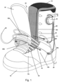
- Cable-based systems deployed from a retractable reel e.g., a reel in tensioning mechanism 24 in Figs. 1 & 3
- a retractable reel e.g., a reel in tensioning mechanism 24 in Figs. 1 & 3
- closure system e.g., a reel in tensioning mechanism 24 in Figs. 1 & 3
- Examples of such systems are found in numerous US and foreign patents, including in the examples listed below, as well as from commercial vendors, such as Boa Technology, Colorado, USA, http://www.boatechnology.com/ .
- the inner liner 16 may include spaced apart edges and a tongue, similar to edges 12d, 12e and tongue 14, and any form of closure system described above.
- the invention relates to tensioning systems that act on one or more cables 120 along a tension path to retract the foot against parts of the boot to better seat the foot in the boot.
- a tensioning mechanism 24 is coupled to the cable(s) to adjustably control tension.
- Such a foot-retraction system may be used in addition to or instead of a conventional closure system, such as those described above.
- tensioning mechanism 24 is a reel-based tensioning mechanism.
- the cables may be of the same nature as described above for the conventional closure systems.
- Arrows T1, T2 and T3 in Figs. 1-2 indicate the direction of force along the tension path when the knob on tensioning mechanism 24 is rotated in direction R, causing tensioning of cable 120, whose ends are disposed on a spooling reel coupled to the knob.
- one or more cables, such as cable 120 may be routed along a tension path from one side of the boot, across the tongue or tongue region 14, to an opposite side of the boot, to create a tension path that tensions the instep, simultaneously causing the bottom side of the user's foot to retract against the footbed and heel areas of the boot. In certain examples, this occurs because at least the tongue 14 is urged rearwardly and downwardly by the tensioned elements in the tension system.
- the tension path extends over the instep area laterally and medially and substantially away from the edges. It continues beyond the edges and wrapping around the sides of the foot or lower leg.
- the extension may be at least 2.5 cm from the edges and in some cases 5.0 cm, 7.5, 10.0 cm, or more.
- a tension path spans the instep or closely adjacent area above and/or below the instep.
- the tension path extends generally laterally and medially from the opposing edges 12d and 12e to the sides of the boot and at a downward angle. It continues at least to points on the lateral and medial sides of the boot that approximately align with the ankle area of the boot.
- a tension path may be constructed so that it passes transversely over longitudinal foot or leg positions ranging from about the metatarsal heads to the front lower leg area.
- the tension path extends to positions on the lateral and/or medial sides of the foot that are at least at or about the ankle.
- One or both terminal ends of such a tension path on a boot may be vertically above, below or over the height of the ankle portion.
- the tension path may extend longitudinally on the foot to a position that is behind the ankle and to the side areas or rear areas of the heel.
- the cable or cables associated with a tension path may be slidably disposed along the path, and therefore tension the shell and/or tongue against the top and/or sides of the user's foot. This tension will tend to cause the foot to retract into the footbed and/or heel areas of the boot.
- the tension path is arranged to provide for a force vector that tensions the boot downwardly and rearwardly against top and sides of the user's foot. The result is that the user's foot is pulled down against the footbed and pulled rearwardly against the heel area, i.e., it is retracted into the areas by virtue of the boot tongue 14 pressing on the top or side surfaces of the foot.
- the tension path may include a portion that is disposed at an angle of about 20 degrees to about 70 degrees from horizontal, providing a direction to the corresponding force vector.
- This downward and rearward vector V is generally indicated in Fig. 3 .
- the cable or cables along such a tension path may interact with the tongue and shell in any one or more ways to tensionably engage those parts.
- one or more sections of one or more cables may be routed over the surfaces of the parts, such as the tongue and shell, and/or the cable or cable sections may be routed in channels or guides 26 through the parts.
- Channels or guides, such as 26a, 26b, and 26c, may be formed in the layer or layers of materials that make up the shell or liner. Guides could be constructed or formed in or on such layers in any number of ways, e.g., leather, synthetic leather, an injected/molded piece, or no guide at all, e.g., just a section of cable over a surface.
- guides or channels such as 26d, 26e, 26f and 26g may be defined by discrete elements that are attached to a boot part and define a segment of a tension path.
- Such elements may include tubes, collars, loops, rings, hooks, etc., that are arranged along a section of a tension path.
- Discrete elements may be most suitable where the tension path needs reinforcement, such as at turns in the path or at anchor points.
- the tension path includes a section that crosses transversely over the outer surface of the tongue 14. Then it extends below the outer surface of outer shell 12, either within the shell layer(s) or on inner surfaces of the shell. Any combination of routing--over surfaces, between surfaces, or on inside surfaces--is contemplated.
- guide elements such as loops, rings, sleeves, tubes, etc., disposed on exterior or interior surfaces, or between surfaces, may be used to define the direction of a segment of a tension path or to facilitate a change in direction of a tension path, while maintaining tensionable engagement with boot parts along a path.
- Guides may be affixed to the surface of the parts or they may be free-floating or repositionable over the parts.
- a free-floating or repositionable element advantageously allows a user to selectively define a tension path and tune the fit of the boot.
- a repositionable guide also may be used in the same or different tension path to allow for clearance of objects through the path.
- a guide may have a portion that snaps or screws into the boot and which can easily be removed by a user's hand so that the user can pull cables out of the opening into which a foot is placed when the boot is taken on or off.
- the Figures show a guide that is integrated with a pressure distribution element 28, e.g., a pad, band, or cuff.
- the guide is disposed over the top of tongue 14.
- the guide includes channels through which cables are slideably routed.
- the pressure distribution pad has a substantially broader surface than the associated cables and thereby distributes the pressure of the cables over a broader surface area.
- the pressure distribution element could be at least 1.0 cm wide and at least 2.0 cm long, in comparison to a cable of not more than a few millimeters in diameter, typically 0.5mm to about 8.0 mm.
- the pressure distribution element 28 shown is not affixed to the tongue or other part of the boot. Rather it is free-floating and vertically and/or laterally repositionable by the user in a desired location over the tongue. It may also self-position according to shape the boot takes with a given foot within it.
- the tongue 14 may have external or internal guides or channels for routing of one or more cables. Guides or channel may be similarly arranged most anywhere else on or in the outer shell parts or other boot parts for routing of the cables.
- the tension path may also continue beyond the paths indicated above.
- the tension path on the lateral side angles or curves upwardly and extends along the side of the boot towards the top of the lateral side of the boot to a tensioning mechanism 24 (discussed in more detail below) for tensioning the cables along the tension path.
- a tensioning mechanism 24 discussed in more detail below
- One or more cables may be disposed along a given tension path. There may also be multiple tension paths, each with one or more cables.
- the tension on a cable in the tension path may be applied in a number of ways.
- the ends of the cable have anchor points that anchor the cable or a segment of the cable in tension.
- the anchor points can be a fixed or adjustable structure of mechanism.
- the end of a cable or segment of a cable is fixed to the point. For example, it is stitched, glued, tied, and/or mechanically captured, to the point.
- an adjustable anchor point the end or the cable or segment of the cable may be repositioned relative to the anchor point and then fixedly captured by it.
- Rotating elements as tensioning mechanisms can also provide leverage based on providing relatively large diameter wheels or levers on a pivot point to which a cable may be connected.
- a wheel of tensioning mechanism may be configured with a diameter that enhances leverage of a cable spool (not shown) to which it is rotatably coupled.
- a tension path has at one end a tensioning mechanism that are operationally clear and independent of the closure system on the edges 12d and 12e.
- the tension path shown is also routed under the closure system (i.e., cable 20 and closure elements 22) so that the cables associated with the tension path and those for the closure system do not impede one another.
- a single cable 80 is disposed on the tension path.
- Each end of the cable is connected to a rotatable tensioning mechanism so that a loop is formed.
- the loop has generally parallel sections 82a, 82b that extend over the instep area 12d.
- the loop has a closed end 82c opposite the rotatable tensioning mechanism 24.
- the loop end 82c is coupled to an anchor point 26c disposed on the side of the boot that is opposite the side of the tensioning mechanism.
- the anchor point is a U-shaped channel 26c or guide through which the end 82c of the loop is routed. It blocks the loop end from pulling forward, allowing simultaneous tensioning of the parallel segments when the free ends are simultaneously tensioned by a tensioning mechanism. If there is not simultaneous tensioning, the cable will slide in the channel shown in the direction of the tensioning. This may be avoided by fixedly attaching the loop end of the strand to an anchor point instead of using a U-shaped channel.
- the anchor point 26c is on the medial side of the boot below and aligned with or behind the ankle area of the boot.
- Parallel sections 82a, 82b route respectively through guides 26a and 26b across the instep area of the boot to turning elements 26d and 26e, e.g., collars or sleeves, that redirect the cable sections upwardly to their anchor points on a reel in the tensioning mechanism 24.
- the sections are windable on the reel and simultaneously tensionable.
- the reel is contained in a housing or on base, and not shown in the Figures. The reel rotates on an axle in housing or base portion of the tensioning mechanism.
- the reel is rotatably coupled to a knob accessible by a user and mounted on the external side of the housing or on the base.
- the tensioning mechanism may include a ratchet mechanism that allows the wheel and reel to be turned by a user to apply tension from the tensioning mechanism across the cable to the medial side anchor element 26c. When tension is applied, the part of the boot that section 26c is integrated is urged toward the opposite part to which the tensioning mechanism is mounted.
- the '521 patent discloses reel system for tensioning a cable on a tension path in an item of footwear.
- the tensioning mechanism may include a wheel that pops out of the housing or base unit affixed to the outer shell of an item of footwear. In the out position, a ratchet in disengaged and the cable tension can be released.
- Tensioning mechanisms include not only reel-based system for retracting cables, but various other tensioning mechanisms, including spring-based clamping systems, turnbuckle systems, and even simple posts, hooks, or other such receivers mountable on a boot or other item of footwear and to which cables can be tied off.
- the single loop could be replaced by two or more individual cables, each with one end anchored to the same or different tensioning mechanisms on one side of the boot and the other end anchored to an anchor point on the other side of the boot.
- the example shown in the picture could be modified by in essence cutting the end of the loop to provide two separate cables emanating from one or more tensioning mechanisms on the opposite side of the instep, in this case the lateral side).
- Each free end on the medial side would be anchored to the same or different anchor points on the medial side.
- a tension path using guides could also be configured to allow for the tensioning mechanism and anchor point to be on the same side of the boot with the tension path crossing to opposite sides of the boot.
- a leverage effect may be provided along any tension path by a having a tensioned cable pass over the instep using turning points over which the tensioned cable slides or pivots.
- a modification to the embodiment shown could be take one cable end of the reel of tensioning mechanism and anchor it anywhere on the same side of the boot as the tensioning mechanism (in this case the lateral side).
- the cable would be slidably disposed over the anchor point at the medial side, which would actually become a turning point.
- the tensioning mechanism would wind the cable at one end and apply tension across the whole tension path, which would be disposed between the two anchor points on the lateral side.
- the cable could have a tension path that crosses the instep multiple times using multiple turning points on opposite sides of the instep to provide multiples of leverage.
- a turning element can be any kind of pivot device that allows for rolling engagement.
- the pivot device could a low friction D-ring, O-ring, a sleeve, collar, a block, a sheave; roller, pulley wheels, etc.
- Figs. 4 through 9 show another possible arrangement of a tensioning system, as described above.
- Figs. 4-5B and 7-9 show external features of the arrangement, and
- Fig. 6 shows a bisected shell revealing internal aspects of the arrangement.
- the tensioning system 100 shown in Figs. 4 through 9 includes an upper cable 110 and a lower cable 120 operatively associated with respective upper and lower tensioners 130, 140 to form respective upper and lower cable loops in a manner described above.
- each of the upper cable 110 and the lower cable 120 defines opposed open ends anchored to a respective tensioner 130, 140, forming a respective loop.
- a tensioning system 100 arranged as shown in Figs. 4 through 9 can draw opposed edges of the shell together with sufficient closure force as not to need or use a separate closure system (e.g., laces, as shown in Figs. 1 through 3 ). Stated differently, a tensioning system 100 arranged as shown in Figs. 4 through 9 can constitute, in some embodiments, a foot retraction system.
- the tensioning system 100 arrangement shown in Figs. 4 through 9 can be used in connection with a boot having a tongue 14 or a boot having a tongue-like element, just as with tensioning systems shown in Figs. 1 through 3 .
- the tensioning system 100 includes a floating element 150 positioned outwardly of the tongue 14 relative to a user's leg.
- the floating element 150 couples the upper loop formed by the upper cable 110 and the lower loop formed by the lower cable 120 to each other.
- an upper segment 121 of the lower loop passes through a lower channel 151 (e.g., a perforation) defined by the floating element 150
- a lower segment 111 of the upper loop passes through an upper channel 152 of the floating element 150.
- a channel permits a sliding engagement between a cable, or a segment thereof, and an adjacent, overlying structural component (e.g., an upper of the boot, the floating element).
- a selected tension applied to the upper cable 110 and a selected tension applied to the lower cable 120 can urge the floating element 150 inwardly of the boot (e.g., toward a user's instep) in a selected manner.
- the floating element 150 in conjunction with the independently tensionable upper and lower cables 110, 120 can, as indicated in Fig.
- a selected force vector T 1a , T 2a (e.g., a selected force magnitude and a selected force direction) to a wearer's instep, providing a user-selectable degree of comfort, together with a user-selectable degree of downward and rearward seating of the wearer's foot in the foot bed and heel in the heel cup.
- the lower cable 120 defines opposed ends captured by a corresponding lower tensioner 140 ( Figs. 5A-9 ).
- the lower tensioner 140 is positioned outwardly of the lateral side of the upper portion 120.
- a position of the lower tensioner 140 can be selected elsewhere for user convenience and comfort without departing from the scope and spirit of this disclosure.
- the opposed ends of the lower cable can be affixed to the lower tensioner 140 such that portions of the lower cable 120 proximate to the lower tensioner 140 can be wound about a reel of the tensioner in a manner as described above.
- a first upper portion of the lower cable 120 can pass into a conduit 161 (or a channel), extending rearwardly of the boot from the lower tensioner 140 on the lateral side 51 of the boot 50 and around a rear portion 53 of the boot 50 in a region adjacent to or slightly above a wearer's Achilles tendon, and to an upper rear portion of the medial side 52 of the boot.
- the first upper portion of the lower cable can be routed downwardly along the rear portion 53 (e.g., a proximal portion) of the medial side 52 of the boot (e.g., along a portion of the boot overlying a region between the wearer's Achilles tendon and a medial protuberance of the ankle) to a lower rear portion of the medial side 52 of the boot.
- the first portion of the lower cable can be routed distally from the lower rear portion 53 of the medial side 52 of the boot 50 to a position 162 of the medial edge of the shell 12 overlying a lower portion of the wearer's instep, indicated by the position of the upper anchor channel 161 (sometimes referred to as an anchor point) for the lower cable 120 in Fig. 6 .
- a second upper portion of the lower cable 120 can pass into a conduit 163 extending rearwardly of the boot 50 from the lower tensioner 140 and downwardly along the rear portion (e.g. a proximal portion) of the lateral side 51 of the boot 50 (e.g., along a portion of the boot overlying a region between the wearer's Achilles tendon and a lateral protuberance of the ankle) to a lower rear portion 53 of the lateral side 51 of the boot 50.
- the rear portion e.g. a proximal portion
- the lateral side 51 of the boot 50 e.g., along a portion of the boot overlying a region between the wearer's Achilles tendon and a lateral protuberance of the ankle
- the second portion of the lower cable 120 can be routed distally from the lower rear portion of the lateral side of the boot to a position 164 of the lateral edge of the shell opposite the position 162 on the medial edge of the shell to which the first portion of the lower cable is routed.
- the first upper portion of the lower cable 120 can span the gap 165 between the medial and the lateral edges of the shell, passing from an upper anchor channel 161 positioned adjacent the medial edge, through the lower channel 151 defined by the floating element 150, and into an upper aperture 164 of a lower anchor channel 168 positioned adjacent the lateral edge of the shell 12.
- the second portion of the lower cable 120 can span the gap 165 between the lateral and the medial edges of the shell, passing from an upper anchor channel 163 positioned adjacent the lateral edge, through the lower channel 151 defined by the floating element 150, and into an upper aperture 167 of a lower anchor channel 168 positioned adjacent the medial edge of the shell.
- An intermediate segment 124 of the lower cable is continuous with and extends between the first upper portion and the second upper portion of the lower cable.
- the intermediate segment 124 can be considered as extending between opposed portions of the lower cable 120 positioned adjacent the upper aperture 164 of the lower anchor channel 168 positioned adjacent the lateral edge of the shell and the upper aperture 167 of the lower anchor channel 169 positioned adjacent the medial edge of the shell.
- a portion of the lower segment spans a distal portion of the gap 165 between the lateral edge and the medial edge of the shell, passing through a lower tongue channel 153.
- an upper tensioner 130 is positioned on the tongue 12, and the upper cable 110 extends laterally and medially outwardly of the upper tensioner 130 into upper apertures 171, 172 of respective lateral and medial upper anchor channels 173, 174.
- the opposed ends of the upper cable can be affixed to the upper tensioner 130 such that portions of the upper cable 110 proximate to the upper tensioner 130 can be wound about a reel of the tensioner in a manner as described above.
- the opposed portions of the upper cable 110 extend through the respective upper anchor channels 173, 174 and outwardly of lower apertures 175, 176 defined by the respective upper anchor channels 173, 174.
- the portion of the upper segment of the upper cable extending from the lateral-side aperture 175 spans the gap 165 between the lateral and the medial edges, passing through an upper tongue channel 154 and into an aperture 177 defined by a lower anchor channel 178 for the upper cable, positioned on the medial side 52 of the shell.
- the portion of the upper segment of the upper cable 110 extending from the medial side aperture 176 spans the gap 165 between the medial and the lateral edges, also passing through the upper tongue channel 154 and into an aperture 179 defined by a lower anchor channel 180 for the upper cable, positioned on the lateral side 51 of the shell.
- the respective medial and lateral lower anchor channels 178, 180 for the upper cable 110 extend rearwardly from the edges of the shell to a position generally rearward of a user's ankle protuberances, downward around the ankle protuberances and forward to a position 181, 182 generally below and slightly forward of the ankle protuberances.
- the position generally below and slightly forward of the ankle protuberances is positioned rearwardly of, and slightly below, the medial edge of the shell, the lateral edge of the shell, or both, as shown in Fig. 6 .
- the cable is seen extending into the boot between the shell 12 and the tongue 14 toward the recessed positions of the opposed lower apertures 181, 182 of the respective lower anchor channels 178, 180.
- An intermediate segment of the upper cable sometimes also referred to as a lower segment 111 (e.g., of the upper cable), extends between the respective medial and lateral apertures 181, 182 defined by the lower anchor channels 178, 180 for the upper cable 110.
- the intermediate segment 111 of the upper cannel can be considered as extending between opposed portions of the upper cable.
- the lower segment 111 of the upper cable 110 extends from the position 181, 182 generally below and slightly forward of the ankle protuberances in correspondence to a flexible region 185 of the boot, as shown in Figs. 4 and 6 .
- the flexible region 185 of the boot can be positioned to correspond to a position of the wearer's flexible ankle joint.
- a selected tension in the upper cable can urge an upper portion 152 of the floating element 150 downwardly and rearwardly against the tongue, urging a wearer's foot downwardly into the foot bed and rearwardly into the heel cup, with greater force T1a as compared to an arrangement in which the cable was routed into an anchor channel having an aperture positioned directly adjacent an edge of the shell.
Landscapes
- Health & Medical Sciences (AREA)
- General Health & Medical Sciences (AREA)
- Physical Education & Sports Medicine (AREA)
- Footwear And Its Accessory, Manufacturing Method And Apparatuses (AREA)
Description
- The inventive subject matter in its various possible embodiments is directed to systems that tension an item of footwear to the foot and/or leg of a user so that the foot or leg is secured within the item during use. The inventive subject matter is particularly suitable for use in boots for snow and skating sports or any other such sport where sliding movement of the foot or leg relative to the item of footwear is undesirable and where secure coupling of the item to the foot and leg facilitates transfer of power to a board, ski, skate blade, set of skate wheels, etc., that is coupled to the item. The inventive subject matter is particularly, but not exclusively, directed to a tensioning system for a snowboard boot that tightens the boot parts around the user's instep or other anatomical areas, retracting the foot into the footbed and simultaneously retracting the heel into the heel area. The system provides a tension path that achieves the foregoing results and routes one or more cables to a tensioning mechanism that can be operated by the user to adjustably increase or decrease cable tension.
- Systems that include a tensionable band or cables over the instep of a boot are known in rigid shell ski boots, for example. The instep tensioning system retracts the foot downwardly against the footbed and rearwardly into the heel area of the footwear item. Such boots are made of stiffer plastic parts and have specially molded features for routing of tensioning cables. Such boots may not allow for easy or precise adjustment of the cable tension. The integration of such systems into boot may also pose manufacturing challenges and may be costly. Further, in the case of snowboard boots, the shells typically have opposing, spaced apart edges and a tongue disposed in the spaced area (sometimes referred to herein as a "gap"). In such boots, a lace or cable-based closure system may be used. Unfortunately, until the inventive subject matter, the integration of a separate instep tensioning system has proven challenging because the conventional closure system and the instep tensioning system may interfere with each other. For example,
US Patent No. 7,386,947 shows a tensioning system using cords and a retractable reel mounted on the upper sides of the boot with the cable routing over the instep. However, the cords are routed using a cumbersome harness assembly disposed within the outer shell of the boot that adds bulk and expense. The system does not integrate directly with the outer shell parts for optimal engagement with those parts. DocumentUS 2004/226190 A1 discloses an item of footwear according to the preamble of claim 1. - The foregoing is not intended to be an exhaustive listing of disadvantages of the prior art and needed improvements; it is only a sampling. In view of the foregoing, there is a substantial need for improved systems for tensioning items of footwear to the feet of users.
- Inventive subject matter disclosed herein overcomes one or more disadvantages of the prior art and provides various improvements. The present invention is defined by an item of footwear according to the appended claim 1. Preferred embodiments are defined by the appended dependent claims.
- In the embodiments contemplated herein, the item of footwear may be a boot for a snow or skating sport.
- In the examples contemplated herein, the closure elements may be adapted to receive laces or other cables. In the examples contemplated herein, a liner in the nature of a removable bootie may be disposed in the shell. In the embodiments contemplated herein, the closure mechanism may include a wheel or knob operable by a user to tension the cable.
- These and other embodiments are described in more detail below and in the accompanying Figures.
- The accompanying drawings in
Figs. 5A through 9 show embodiments according to the inventive subject matter. -
Figs. 1 through 9 show left boot embodiments. Left and right boots are mirror images of each other. -
Fig. 1 shows a lateral perspective view of a boot with a tensioning system in an untensioned condition. -
Fig. 2 shows a medial perspective view of the boot inFig.1 -
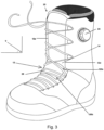
Fig. 3 shows another lateral view of the boot inFig. 1 , in this case with the tensioning system under tension and engaging boot parts. -
Fig. 4 shows a partial front view of a left boot with another tensioning system in a tensioned condition. -
Fig. 5A shows a lateral, side-elevation view of the boot and tensioning system shown inFig. 4 in an untensioned condition. -
Fig. 5B shows a lateral perspective view of the boot and tensioning system shown inFigs. 4 and5A . -
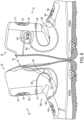
Fig. 6 shows a shell of a left boot bisected along a plane dividing the medial side of the boot from the lateral side of the boot, revealing internal features of the shell and the tensioning system. -
Fig. 7 shows a lateral, side elevation view of the boot shown inFig. 4 , with the tensioning system in a tensioned condition and a portion of the lateral eyerow folded down to reveal features of the tongue. -
Fig. 8 shows a lateral view of the boot shown inFig. 7 with the eyerow folded up. -
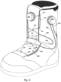
Fig. 9 shows a lateral perspective view of the boot as shown inFig. 8 . - Representative embodiments incorporating one or more aspects of the inventive subject matter are shown in
Figs. 5A through 9 , wherein the same or generally similar features share common reference numerals. - In broad terms, an item of footwear is configured with a foot retraction system for closing around the foot and retracting a portion of the footwear against a user's foot into the footbed and heel area of the item. In certain respects, disclosed innovations generally pertain to systems for tensioning a boot to the foot of a user so that the foot is retracted as so. The inventive subject matter is particularly useful with snowboarding boots. It can also be used with a variety of other kinds of boots, including ski boots, skate boots, hiking boots, and any other kind of footwear where it is desirable to engage an item footwear around the foot and keep the foot from lifting or sliding in the item of footwear.
- For illustrative purposes, a snowboard boot will be used as a representative boot in which the inventive subject matter may be embodied. From the following discussion, persons skilled in the art will understand how the inventive subject matter may be embodied in other forms of boots and footwear. A
snowboard boot 10 typically has anouter shell 12. The shell is typically a semi-rigid structure made of an assembly of materials, such as one or more of sheets or layers of natural or synthetic leathers, woven or non-woven textiles, and plastics and rubbers. Some or all of the shell may be made of molded plastics or rubbers. The boot includes atongue 14. The tongue is part of the shell - The boot may have an
inner liner 16, which is usually a removable bootie but it can also be built into theshell 12. A footbed for receiving the bottom of the user's foot is part of the boot, and may be formed in the liner material or it may be a separate structure. The boot also includes a heel cup for wrapping around and receiving the heel of a user. It is typically formed in the liner. In the representative embodiment shown in the Figures, opposing edges ofshell 12 are spaced apart and in-filled bytongue 14. - The outer shell includes an
upper portion 12a that extends upward from the instep, over the ankle, and around a lower leg portion of a user. The shell also includes a proximalfoot enclosure portion 12b, enclosing the general areas of the instep and heel and adistal portion 12c for enclosing the top and sides of the midfoot and forefoot. The boot includes a sole 18 that connects to shell 12 and covers the bottom of the user's foot. - The
outer shell 12 in a snowboard boot is made up of relatively stiff and rugged materials, such as leathers and semi-rigid or rigid plastics, rubbers, or other such materials. The shell may include an inner liner that is typically made up of a thickened set of materials that provide cushioning, comfort, and insulation to a user's foot. For example, the liner may be made of a core of foamed polyurethane (PU) or ethyl vinyl acetate (EVA) materials with outer and inner linings of a textile or fabric. Theinner liner 16 may also be a separate removable component such as a bootie. The tongue ortongue region 14 of the boot may be constructed in a way that is similar to that of the liner. - The sole may be made of rubber, EVA, PU and other known midsole and outsole materials alone or in combination. The shell and soles may be lasted together using any known or developed techniques, including board lasting.
- In the embodiment shown in the Figures, the upper portion of the
shell 12 has spaced-apart, vertically-orientededges tongue 14 is disposed on the boot in the spacing between the edges. -
Boot 10 has aflex zone 13 that generally corresponds to the ankle joint of the intended wearer. The ankle joint is a hinging joint between the foot and the leg. The uppermost bone of the foot, called the talus (ankle-bone), is disposed between the two bony protuberances formed by the lower ends of the tibia (shin bone) and the fibula. By tensioning the boot over the ankle's hinge joint, the element can cause the foot to be secured over the sole of the boot, allowing for precise and controlled flexation and transmission of power to a snowboard. -
Boot 10 may include a closure system that provides for converging of the opposingedges suitable cable 20 may include any form of shoe or boot lace, cables of bundled metal fibers or of non-metals, strings, cords, chains, leather strips, etc.Closure elements 22 in a cable-based closure or tensioning system may be any combination of loops, hooks, eyelets, gilleys, and other such structures that can receive a cable. Mechanical closure systems are also well known. In a mechanical closure system, the closure elements may be buckles, straps (e.g., belt style or Velcro style), clamps, etc. - In the representative example of the Figures, sets of
closure elements 22, of the same or different forms, are arranged alongedges Closure systems 22 for snowboard boots and various other kinds of boots are generally centered over the front of the lower leg and the top of the foot. They typically do not extend substantially beyond such centralized areas to the side portions of the boot. To illustrate the operation of a closure system,Fig. 2 showsboot 10 withedges Fig. 3 shows them converged together and overtongue 12. - Cable-based systems deployed from a retractable reel, e.g., a reel in
tensioning mechanism 24 inFigs. 1 &3 , are another form of closure system that may be used to draw together opposingedges - The
inner liner 16 may include spaced apart edges and a tongue, similar toedges tongue 14, and any form of closure system described above. - The invention relates to tensioning systems that act on one or
more cables 120 along a tension path to retract the foot against parts of the boot to better seat the foot in the boot. Atensioning mechanism 24 is coupled to the cable(s) to adjustably control tension. Such a foot-retraction system may be used in addition to or instead of a conventional closure system, such as those described above. In the example shown,tensioning mechanism 24 is a reel-based tensioning mechanism. The cables may be of the same nature as described above for the conventional closure systems. - Arrows T1, T2 and T3 in
Figs. 1-2 indicate the direction of force along the tension path when the knob ontensioning mechanism 24 is rotated in direction R, causing tensioning ofcable 120, whose ends are disposed on a spooling reel coupled to the knob. In certain embodiments, such as the one shown, one or more cables, such ascable 120, may be routed along a tension path from one side of the boot, across the tongue ortongue region 14, to an opposite side of the boot, to create a tension path that tensions the instep, simultaneously causing the bottom side of the user's foot to retract against the footbed and heel areas of the boot. In certain examples, this occurs because at least thetongue 14 is urged rearwardly and downwardly by the tensioned elements in the tension system. - In contrast to conventional closure systems arranged on opposing edges, such as
edges - More particularly, in the example shown, a tension path spans the instep or closely adjacent area above and/or below the instep. (Hereinafter the instep and closely adjacent areas may be referred to as the "instep area"). The tension path extends generally laterally and medially from the opposing
edges - While the Figures show a tension path crossing over the instep area of a boot, the it is also contemplated that a tension path may be constructed so that it passes transversely over longitudinal foot or leg positions ranging from about the metatarsal heads to the front lower leg area. In such cases, the tension path extends to positions on the lateral and/or medial sides of the foot that are at least at or about the ankle. One or both terminal ends of such a tension path on a boot may be vertically above, below or over the height of the ankle portion. In certain examples, the tension path may extend longitudinally on the foot to a position that is behind the ankle and to the side areas or rear areas of the heel.
- The cable or cables associated with a tension path may be slidably disposed along the path, and therefore tension the shell and/or tongue against the top and/or sides of the user's foot. This tension will tend to cause the foot to retract into the footbed and/or heel areas of the boot. In the embodiment shown, the tension path is arranged to provide for a force vector that tensions the boot downwardly and rearwardly against top and sides of the user's foot. The result is that the user's foot is pulled down against the footbed and pulled rearwardly against the heel area, i.e., it is retracted into the areas by virtue of the
boot tongue 14 pressing on the top or side surfaces of the foot. In the various tension paths contemplated herein providing a downward and rearward force vector, the tension path may include a portion that is disposed at an angle of about 20 degrees to about 70 degrees from horizontal, providing a direction to the corresponding force vector. This downward and rearward vector V is generally indicated inFig. 3 . - The cable or cables along such a tension path may interact with the tongue and shell in any one or more ways to tensionably engage those parts. For example, one or more sections of one or more cables may be routed over the surfaces of the parts, such as the tongue and shell, and/or the cable or cable sections may be routed in channels or guides 26 through the parts. Channels or guides, such as 26a, 26b, and 26c, may be formed in the layer or layers of materials that make up the shell or liner. Guides could be constructed or formed in or on such layers in any number of ways, e.g., leather, synthetic leather, an injected/molded piece, or no guide at all, e.g., just a section of cable over a surface.
- In addition to guides or channels that are integrated into a boot part, guides or channels, such as 26d, 26e, 26f and 26g may be defined by discrete elements that are attached to a boot part and define a segment of a tension path. Such elements may include tubes, collars, loops, rings, hooks, etc., that are arranged along a section of a tension path. Discrete elements may be most suitable where the tension path needs reinforcement, such as at turns in the path or at anchor points. In the example shown, the tension path includes a section that crosses transversely over the outer surface of the
tongue 14. Then it extends below the outer surface ofouter shell 12, either within the shell layer(s) or on inner surfaces of the shell. Any combination of routing--over surfaces, between surfaces, or on inside surfaces--is contemplated. - From the foregoing, it will be understood that guide elements, such as loops, rings, sleeves, tubes, etc., disposed on exterior or interior surfaces, or between surfaces, may be used to define the direction of a segment of a tension path or to facilitate a change in direction of a tension path, while maintaining tensionable engagement with boot parts along a path. Guides may be affixed to the surface of the parts or they may be free-floating or repositionable over the parts. A free-floating or repositionable element advantageously allows a user to selectively define a tension path and tune the fit of the boot. A repositionable guide also may be used in the same or different tension path to allow for clearance of objects through the path. For example, a guide may have a portion that snaps or screws into the boot and which can easily be removed by a user's hand so that the user can pull cables out of the opening into which a foot is placed when the boot is taken on or off.
- The Figures show a guide that is integrated with a
pressure distribution element 28, e.g., a pad, band, or cuff. The guide is disposed over the top oftongue 14. The guide includes channels through which cables are slideably routed. The pressure distribution pad has a substantially broader surface than the associated cables and thereby distributes the pressure of the cables over a broader surface area. For example, the pressure distribution element could be at least 1.0 cm wide and at least 2.0 cm long, in comparison to a cable of not more than a few millimeters in diameter, typically 0.5mm to about 8.0 mm. Thepressure distribution element 28 shown is not affixed to the tongue or other part of the boot. Rather it is free-floating and vertically and/or laterally repositionable by the user in a desired location over the tongue. It may also self-position according to shape the boot takes with a given foot within it. - In other examples, a separate pressure element is not necessary and the tongue itself may serve that role. The
tongue 14 may have external or internal guides or channels for routing of one or more cables. Guides or channel may be similarly arranged most anywhere else on or in the outer shell parts or other boot parts for routing of the cables. - The tension path may also continue beyond the paths indicated above. For example, in the Figures, the tension path on the lateral side angles or curves upwardly and extends along the side of the boot towards the top of the lateral side of the boot to a tensioning mechanism 24 (discussed in more detail below) for tensioning the cables along the tension path. Such a routing allows a user to more easily reach and manipulate the tensioning mechanism to adjustably increase or decrease tension.
- One or more cables may be disposed along a given tension path. There may also be multiple tension paths, each with one or more cables. The tension on a cable in the tension path may be applied in a number of ways. In each case, the ends of the cable have anchor points that anchor the cable or a segment of the cable in tension. The anchor points can be a fixed or adjustable structure of mechanism. At a fixed anchor point, the end of a cable or segment of a cable is fixed to the point. For example, it is stitched, glued, tied, and/or mechanically captured, to the point. In an adjustable anchor point, the end or the cable or segment of the cable may be repositioned relative to the anchor point and then fixedly captured by it. For example, there are various known spring-based clamping mechanisms for engaging a clamping element against a cable. The spring force against the clamping device fixes the cable in clamping mechanism. Depressing the spring elements disengages the clamping element and allows a user to adjust cord or cable tension.
- Devices that can provide mechanical advantage or leverage when associated with a cable include shackles, blocks, pulleys, sheaves, and geared systems with reduction gears. Rotating elements as tensioning mechanisms can also provide leverage based on providing relatively large diameter wheels or levers on a pivot point to which a cable may be connected. For example, a wheel of tensioning mechanism may be configured with a diameter that enhances leverage of a cable spool (not shown) to which it is rotatably coupled.
- In the example shown in the Figures, a tension path has at one end a tensioning mechanism that are operationally clear and independent of the closure system on the
edges cable 20 and closure elements 22) so that the cables associated with the tension path and those for the closure system do not impede one another. In the example shown, asingle cable 80 is disposed on the tension path. Each end of the cable is connected to a rotatable tensioning mechanism so that a loop is formed. The loop has generallyparallel sections instep area 12d. The loop has aclosed end 82c opposite therotatable tensioning mechanism 24. Theloop end 82c is coupled to ananchor point 26c disposed on the side of the boot that is opposite the side of the tensioning mechanism. In this example, the anchor point is aU-shaped channel 26c or guide through which theend 82c of the loop is routed. It blocks the loop end from pulling forward, allowing simultaneous tensioning of the parallel segments when the free ends are simultaneously tensioned by a tensioning mechanism. If there is not simultaneous tensioning, the cable will slide in the channel shown in the direction of the tensioning. This may be avoided by fixedly attaching the loop end of the strand to an anchor point instead of using a U-shaped channel. - In the example shown in the Figures, the
anchor point 26c is on the medial side of the boot below and aligned with or behind the ankle area of the boot.Parallel sections guides elements tensioning mechanism 24. By connecting the ends of the cable sections to the reel, the sections are windable on the reel and simultaneously tensionable. The reel is contained in a housing or on base, and not shown in the Figures. The reel rotates on an axle in housing or base portion of the tensioning mechanism. The reel is rotatably coupled to a knob accessible by a user and mounted on the external side of the housing or on the base. The tensioning mechanism may include a ratchet mechanism that allows the wheel and reel to be turned by a user to apply tension from the tensioning mechanism across the cable to the medialside anchor element 26c. When tension is applied, the part of the boot thatsection 26c is integrated is urged toward the opposite part to which the tensioning mechanism is mounted. - Examples of suitable reel-based tensioning mechanisms are found in the following patents:
US 7,082,701 , in the name of Vans, Inc.,US 4,748,726 , and7,512,521 . The '521 patent discloses reel system for tensioning a cable on a tension path in an item of footwear. The '521 patent discloses that the tensioning mechanism may include a wheel that pops out of the housing or base unit affixed to the outer shell of an item of footwear. In the out position, a ratchet in disengaged and the cable tension can be released. - Tensioning mechanisms include not only reel-based system for retracting cables, but various other tensioning mechanisms, including spring-based clamping systems, turnbuckle systems, and even simple posts, hooks, or other such receivers mountable on a boot or other item of footwear and to which cables can be tied off.
- While the foregoing system is described in terms of a single cable in a loop, it will be understood by persons skilled in the art that the single loop could be replaced by two or more individual cables, each with one end anchored to the same or different tensioning mechanisms on one side of the boot and the other end anchored to an anchor point on the other side of the boot. The example shown in the picture could be modified by in essence cutting the end of the loop to provide two separate cables emanating from one or more tensioning mechanisms on the opposite side of the instep, in this case the lateral side). Each free end on the medial side would be anchored to the same or different anchor points on the medial side. A tension path using guides could also be configured to allow for the tensioning mechanism and anchor point to be on the same side of the boot with the tension path crossing to opposite sides of the boot.
- A leverage effect may be provided along any tension path by a having a tensioned cable pass over the instep using turning points over which the tensioned cable slides or pivots. For example, a modification to the embodiment shown could be take one cable end of the reel of tensioning mechanism and anchor it anywhere on the same side of the boot as the tensioning mechanism (in this case the lateral side). The cable would be slidably disposed over the anchor point at the medial side, which would actually become a turning point. The tensioning mechanism would wind the cable at one end and apply tension across the whole tension path, which would be disposed between the two anchor points on the lateral side. The cable could have a tension path that crosses the instep multiple times using multiple turning points on opposite sides of the instep to provide multiples of leverage. A turning element can be any kind of pivot device that allows for rolling engagement. For example, the pivot device could a low friction D-ring, O-ring, a sleeve, collar, a block, a sheave; roller, pulley wheels, etc.
-
Figs. 4 through 9 show another possible arrangement of a tensioning system, as described above.Figs. 4-5B and7-9 show external features of the arrangement, andFig. 6 shows a bisected shell revealing internal aspects of the arrangement. - The
tensioning system 100 shown inFigs. 4 through 9 includes anupper cable 110 and alower cable 120 operatively associated with respective upper andlower tensioners upper cable 110 and thelower cable 120 defines opposed open ends anchored to arespective tensioner - Such an arrangement permits the
upper cable 110 and thelower cable 120 to be selectively tensioned independently of each other. Additionally, atensioning system 100 arranged as shown inFigs. 4 through 9 can draw opposed edges of the shell together with sufficient closure force as not to need or use a separate closure system (e.g., laces, as shown inFigs. 1 through 3 ). Stated differently, atensioning system 100 arranged as shown inFigs. 4 through 9 can constitute, in some embodiments, a foot retraction system. - The
tensioning system 100 arrangement shown inFigs. 4 through 9 can be used in connection with a boot having atongue 14 or a boot having a tongue-like element, just as with tensioning systems shown inFigs. 1 through 3 . InFigs. 4 through 9 , thetensioning system 100 includes a floatingelement 150 positioned outwardly of thetongue 14 relative to a user's leg. - The floating
element 150 couples the upper loop formed by theupper cable 110 and the lower loop formed by thelower cable 120 to each other. In particular, as shown inFig. 4 , anupper segment 121 of the lower loop passes through a lower channel 151 (e.g., a perforation) defined by the floatingelement 150, and alower segment 111 of the upper loop passes through anupper channel 152 of the floatingelement 150. As with tensioning systems described in detail above, a channel permits a sliding engagement between a cable, or a segment thereof, and an adjacent, overlying structural component (e.g., an upper of the boot, the floating element). - With an engagement between the floating
element 150 and the upper and thelower cables upper cable 110 and a selected tension applied to thelower cable 120 can urge the floatingelement 150 inwardly of the boot (e.g., toward a user's instep) in a selected manner. As but one example, with such a configuration, the floatingelement 150 in conjunction with the independently tensionable upper andlower cables Fig. 5B , apply a selected force vector T1a, T2a (e.g., a selected force magnitude and a selected force direction) to a wearer's instep, providing a user-selectable degree of comfort, together with a user-selectable degree of downward and rearward seating of the wearer's foot in the foot bed and heel in the heel cup. - For convenience, routing of the
upper cable 110 and routing of thelower cable 120 are now described in relation toFigs. 4 through 9 . Nonetheless, other arrangements of cables and tensioners are possible and contemplated to be within the level of ordinary skill following a review of this disclosure. - As noted above, the
lower cable 120 defines opposed ends captured by a corresponding lower tensioner 140 (Figs. 5A-9 ). With the arrangement depicted inFigs. 4 through 9 , thelower tensioner 140 is positioned outwardly of the lateral side of theupper portion 120. A position of thelower tensioner 140 can be selected elsewhere for user convenience and comfort without departing from the scope and spirit of this disclosure. - The opposed ends of the lower cable can be affixed to the
lower tensioner 140 such that portions of thelower cable 120 proximate to thelower tensioner 140 can be wound about a reel of the tensioner in a manner as described above. - With a routing as shown in
Figs. 5A-9 , a first upper portion of thelower cable 120 can pass into a conduit 161 (or a channel), extending rearwardly of the boot from thelower tensioner 140 on thelateral side 51 of theboot 50 and around arear portion 53 of theboot 50 in a region adjacent to or slightly above a wearer's Achilles tendon, and to an upper rear portion of themedial side 52 of the boot. The first upper portion of the lower cable can be routed downwardly along the rear portion 53 (e.g., a proximal portion) of themedial side 52 of the boot (e.g., along a portion of the boot overlying a region between the wearer's Achilles tendon and a medial protuberance of the ankle) to a lower rear portion of themedial side 52 of the boot. The first portion of the lower cable can be routed distally from the lowerrear portion 53 of themedial side 52 of theboot 50 to aposition 162 of the medial edge of theshell 12 overlying a lower portion of the wearer's instep, indicated by the position of the upper anchor channel 161 (sometimes referred to as an anchor point) for thelower cable 120 inFig. 6 . - With a routing as shown in
Fig. 6 , a second upper portion of thelower cable 120 can pass into aconduit 163 extending rearwardly of theboot 50 from thelower tensioner 140 and downwardly along the rear portion (e.g. a proximal portion) of thelateral side 51 of the boot 50 (e.g., along a portion of the boot overlying a region between the wearer's Achilles tendon and a lateral protuberance of the ankle) to a lowerrear portion 53 of thelateral side 51 of theboot 50. The second portion of thelower cable 120 can be routed distally from the lower rear portion of the lateral side of the boot to aposition 164 of the lateral edge of the shell opposite theposition 162 on the medial edge of the shell to which the first portion of the lower cable is routed. - As shown in
Figs. 4-9 , the first upper portion of thelower cable 120 can span thegap 165 between the medial and the lateral edges of the shell, passing from anupper anchor channel 161 positioned adjacent the medial edge, through thelower channel 151 defined by the floatingelement 150, and into anupper aperture 164 of alower anchor channel 168 positioned adjacent the lateral edge of theshell 12. As also shown inFig. 4 , the second portion of thelower cable 120 can span thegap 165 between the lateral and the medial edges of the shell, passing from anupper anchor channel 163 positioned adjacent the lateral edge, through thelower channel 151 defined by the floatingelement 150, and into anupper aperture 167 of alower anchor channel 168 positioned adjacent the medial edge of the shell. - An
intermediate segment 124 of the lower cable, sometimes also referred to as a lower segment, is continuous with and extends between the first upper portion and the second upper portion of the lower cable. For ease of reference, theintermediate segment 124 can be considered as extending between opposed portions of thelower cable 120 positioned adjacent theupper aperture 164 of thelower anchor channel 168 positioned adjacent the lateral edge of the shell and theupper aperture 167 of thelower anchor channel 169 positioned adjacent the medial edge of the shell. As shown inFig. 4 , a portion of the lower segment spans a distal portion of thegap 165 between the lateral edge and the medial edge of the shell, passing through alower tongue channel 153. - As noted above, when a selected tension is applied to the
lower cable 120, distal portions of the opposed medial and lateral edges of the shell are urged together by forces applied to thechannels cable 120, and a lower portion (e.g., a distal portion) of the floatingelement 150 is drawn toward the user's instep in a direction and with a force magnitude (e.g., force vector T2a) at least partially corresponding to a selected tension and relative positions of the user's instep, the lateral edge, and the medial edge (e.g., since the apertures of thechannels - Arrangements of the
upper cable 110 will now be described. InFig. 4 , anupper tensioner 130 is positioned on thetongue 12, and theupper cable 110 extends laterally and medially outwardly of theupper tensioner 130 intoupper apertures upper anchor channels - The opposed ends of the upper cable can be affixed to the
upper tensioner 130 such that portions of theupper cable 110 proximate to theupper tensioner 130 can be wound about a reel of the tensioner in a manner as described above. The opposed portions of theupper cable 110 extend through the respectiveupper anchor channels lower apertures upper anchor channels - The portion of the upper segment of the upper cable extending from the lateral-
side aperture 175 spans thegap 165 between the lateral and the medial edges, passing through anupper tongue channel 154 and into anaperture 177 defined by alower anchor channel 178 for the upper cable, positioned on themedial side 52 of the shell. The portion of the upper segment of theupper cable 110 extending from themedial side aperture 176 spans thegap 165 between the medial and the lateral edges, also passing through theupper tongue channel 154 and into anaperture 179 defined by alower anchor channel 180 for the upper cable, positioned on thelateral side 51 of the shell. - As shown in
Fig. 6 , the respective medial and laterallower anchor channels upper cable 110 extend rearwardly from the edges of the shell to a position generally rearward of a user's ankle protuberances, downward around the ankle protuberances and forward to aposition Fig. 6 . InFig. 4 , the cable is seen extending into the boot between theshell 12 and thetongue 14 toward the recessed positions of the opposedlower apertures lower anchor channels - An intermediate segment of the upper cable, sometimes also referred to as a lower segment 111 (e.g., of the upper cable), extends between the respective medial and
lateral apertures lower anchor channels upper cable 110. For ease of reference, theintermediate segment 111 of the upper cannel can be considered as extending between opposed portions of the upper cable. - In some embodiments, the
lower segment 111 of theupper cable 110 extends from theposition flexible region 185 of the boot, as shown inFigs. 4 and6 . Theflexible region 185 of the boot can be positioned to correspond to a position of the wearer's flexible ankle joint. With such an arrangement of the upper cable 110 (e.g., an arrangement in which the lower segment extends from the lower channel as a position "deep within the boot"), a selected tension in the upper cable can urge anupper portion 152 of the floatingelement 150 downwardly and rearwardly against the tongue, urging a wearer's foot downwardly into the foot bed and rearwardly into the heel cup, with greater force T1a as compared to an arrangement in which the cable was routed into an anchor channel having an aperture positioned directly adjacent an edge of the shell. - As used herein, "and/or" means "and" or "or", as well as "and" and "or."
- The principles described above in connection with any particular example can be combined with the principles described in connection with any one or more of the other examples. Accordingly, this detailed description shall not be construed in a limiting sense, and following a review of this disclosure, those of ordinary skill in the art will appreciate the wide variety of lending systems and other systems that can be devised using the various concepts described herein. Moreover, those of ordinary skill in the art will appreciate that the exemplary embodiments disclosed herein can be adapted to various configurations without departing from the disclosed principles.
- The previous description of the disclosed embodiments is provided to enable any person skilled in the art to make or use the disclosed innovations. Various modifications to those embodiments will be readily apparent to those skilled in the art, and the generic principles defined herein may be applied to other embodiments.
- Thus, the claimed inventions are not intended to be limited to the embodiments shown herein, but are to be accorded the full scope consistent with the language of the claims, wherein reference to an element in the singular, such as by use of the article "a" or "an" is not intended to mean "one and only one" unless specifically so stated, but rather "one or more".
Claims (14)
- An item of footwear, comprising:a shell (12) for enclosing a foot and at least a portion of a lower leg, the shell having a pair of opposing edges generally aligned along a top-of-foot portion of the shell and/or a front-lower-leg portion, the edges generally aligning with a longitudinal axis of a wearer's foot and/or lower leg, the opposing edges defining medial and lateral sides (51, 52) of the shell (12), and a tongue (14) positioned between the opposing edges; anda tensioning system (100), constituting a foot retraction system, comprising:a lower tension path further comprising at least lower two anchor channels (161, 168) disposed along the lower tension path on a lateral side of the item and supporting a lower tensionable cable (120) disposed along the lower tension path, and a lower tensioning mechanism (140), the lower tensioning mechanism (140) configured to adjust tension in the lower tensionable cable (120);an upper tension path further comprising at least two upper anchor channels (173, 174) disposed along the upper tension path on lateral and medial sides of the item, respectively, and supporting an upper tensionable cable (110) disposed along the upper tension path, and an upper tensioning mechanism (130), the upper tensioning mechanism (130) configured to adjust tension in the upper tensionable cable (110); andcharacterized in that the tensioning system (100) further comprises:
a floating element (150) positioned outwardly of the tongue (14) relative to a user's leg, wherein the floating element (150) couples an upper loop formed by the upper cable (110) and a lower loop formed by the lower cable (120) to each other, in that an upper segment (121) of the lower loop passes through a lower channel (151) defined by the floating element (150), and a lower segment (111) of the upper loop passes through an upper channel (152) of the floating element (150), wherein a floating element channel permits a sliding engagement between a cable, or a segment thereof, and an adjacent, overlying structural component.. - The item of claim 1, wherein the item comprises a boot for a snow or skating sport.
- The item of claim 1, wherein the floating element (150), the first tension path (110) and second tension path (120) apply a selected force magnitude and a selected force direction (T1a, T2a) to the instep area.
- The item of claim 1, wherein the lower tension path further comprises a lower tensionable cable loop and the upper tension path further comprises an upper tensionable cable loop.
- The item of claim 4, wherein the floating element couples the lower tensionable cable loop and the upper tensionable cable loop together.
- The item of claim 1, wherein lower tensionable cable and the upper tensionable cable are configured to be to be selectively tensioned independently of each other.
- The item of claim 1, wherein at least one of the lower tensioning mechanism (140) or the upper tensioning mechanism (130) comprises a reel-base mechanism or a wheel or knob operable by a user to tension the tensionable cable section.
- The item of claim 1, wherein a first upper portion of the lower tensionable cable (120) passes into a first channel (161) and extends rearwardly of the item from the lower tensioning mechanism (140) disposed on the lateral side (51) of the shell (12) and around a lower rear portion (53) of the shell in a region adjacent to or slightly above a wearer's Achilles tendon to an upper rear portion of the medial side (52) of the shell.
- The item of claim 8, wherein the first upper portion of the lower tensionable cable (120) is routed downwardly along the rear portion (53) of the medial side (52) of the shell along a portion of the boot overlying a region between the wearer's Achilles tendon and a medial protuberance of the ankle to a lower rear portion of the medial side (52) of the shell (12).
- The item of claim 9, wherein the first upper portion of the lower tensionable cable (120) is routed distally from the lower rear portion (53) of the medial side (52) of the shell (12) to a medial edge position (162) overlying a lower portion of the wearer's instep.
- The item of claim 10, wherein a second upper portion of the lower tensionable cable (120) passes into second channel (163) extending rearwardly of the shell (12) from the lower tensioning mechanism (140) and downwardly along the lower rear portion (53) of the lateral side (51) of the shell (12) along a portion of the boot overlying a region between the wearer's Achilles tendon and a lateral protuberance of the ankle to the lower rear portion (53) of the lateral side (51) of the shell (12).
- The item of claim 11, wherein the second upper portion of the lower tensionable cable 120 is routed distally from the lower rear portion (53) of the lateral side (51) of the shell (12) to a lateral edge position (164) opposite the medial edge position (162) to which the first upper portion of the lower tensionable cable (120) is routed.
- The item of claim 1, wherein the upper tensioning mechanism (130) is positioned on the tongue (14), and the upper tensioning cable (110) extends laterally and medially outwardly of the upper tensioning mechanism (130) into upper anchor apertures (171, 172) of respective upper anchor channels (173, 174).
- The item of claim 13, wherein opposed portions of the upper tensioning cable (110) extend through respective upper anchor channels (173, 174) and outwardly of respective lower apertures (175, 176) defined by the respective upper anchor channels (173, 174).
Applications Claiming Priority (4)
| Application Number | Priority Date | Filing Date | Title |
|---|---|---|---|
| US201261737628P | 2012-12-14 | 2012-12-14 | |
| US201361866533P | 2013-08-15 | 2013-08-15 | |
| PCT/US2013/075163 WO2014093913A1 (en) | 2012-12-14 | 2013-12-13 | Tensioning systems for footwear |
| EP13862554.6A EP2931074B1 (en) | 2012-12-14 | 2013-12-13 | Tensioning systems for footwear |
Related Parent Applications (2)
| Application Number | Title | Priority Date | Filing Date |
|---|---|---|---|
| EP13862554.6A Division-Into EP2931074B1 (en) | 2012-12-14 | 2013-12-13 | Tensioning systems for footwear |
| EP13862554.6A Division EP2931074B1 (en) | 2012-12-14 | 2013-12-13 | Tensioning systems for footwear |
Publications (2)
| Publication Number | Publication Date |
|---|---|
| EP3725176A1 EP3725176A1 (en) | 2020-10-21 |
| EP3725176B1 true EP3725176B1 (en) | 2025-06-25 |
Family
ID=50935015
Family Applications (2)
| Application Number | Title | Priority Date | Filing Date |
|---|---|---|---|
| EP13862554.6A Active EP2931074B1 (en) | 2012-12-14 | 2013-12-13 | Tensioning systems for footwear |
| EP20173088.4A Active EP3725176B1 (en) | 2012-12-14 | 2013-12-13 | Tensioning systems for footwear |
Family Applications Before (1)
| Application Number | Title | Priority Date | Filing Date |
|---|---|---|---|
| EP13862554.6A Active EP2931074B1 (en) | 2012-12-14 | 2013-12-13 | Tensioning systems for footwear |
Country Status (9)
| Country | Link |
|---|---|
| US (2) | US10383403B2 (en) |
| EP (2) | EP2931074B1 (en) |
| JP (1) | JP6185600B2 (en) |
| KR (2) | KR101808931B1 (en) |
| CN (1) | CN104981174B (en) |
| CA (2) | CA2895246C (en) |
| ES (2) | ES3035136T3 (en) |
| RU (1) | RU2642046C2 (en) |
| WO (1) | WO2014093913A1 (en) |
Families Citing this family (30)
| Publication number | Priority date | Publication date | Assignee | Title |
|---|---|---|---|---|
| EP4327688B1 (en) | 2012-08-31 | 2026-01-14 | Nike Innovate C.V. | Motorized tensioning system with sensors |
| US10076160B2 (en) | 2013-06-05 | 2018-09-18 | Boa Technology Inc. | Integrated closure device components and methods |
| US20150359296A1 (en) * | 2014-06-17 | 2015-12-17 | The Burton Corporation | Lacing system for footwear |
| KR102756327B1 (en) * | 2015-05-29 | 2025-01-16 | 나이키 이노베이트 씨.브이. | Motorized tensioning device with compact spool system |
| ITUB20160158A1 (en) * | 2016-01-15 | 2017-07-15 | Scarpa Calzaturificio Spa | SKI BOOT |
| US10130138B2 (en) * | 2016-01-22 | 2018-11-20 | Apex Sports Group, Llc | Exoskeletal boot |
| US10244822B2 (en) * | 2016-03-15 | 2019-04-02 | Nike, Inc. | Lace routing pattern of a lacing system for an article of footwear |
| US11026472B2 (en) * | 2016-07-22 | 2021-06-08 | Nike, Inc. | Dynamic lacing system |
| EP3534744B1 (en) | 2016-11-01 | 2021-03-24 | Nike Innovate C.V. | Lace guide for an article of footwear |
| US9918516B1 (en) * | 2017-02-08 | 2018-03-20 | LNZ Products Inc. | Lace 'N lock shoe tying system |
| US11484425B2 (en) * | 2017-12-15 | 2022-11-01 | Stoko Design Inc. | Apparatus and method for stabilizing a human anatomical joint |
| WO2019169581A1 (en) | 2018-03-07 | 2019-09-12 | 孙寅贵 | Ski boot |
| WO2020107102A1 (en) * | 2018-11-29 | 2020-06-04 | Powerlace Technologies Inc. | Closure system and footwear therewith |
| EP4678055A3 (en) * | 2019-02-01 | 2026-04-15 | Boa Technology, Inc. | Reel based closure devices for tightening a ski boot |
| US11311997B2 (en) * | 2019-03-07 | 2022-04-26 | Ossur Iceland Ehf | Adapter for a rotary device |
| CN113993412A (en) * | 2019-06-19 | 2022-01-28 | 耐克创新有限合伙公司 | Knitted parts with insert elements |
| WO2021068166A1 (en) * | 2019-10-10 | 2021-04-15 | 孙寅贵 | Boot suitable for skiing and general use |
| JP2023508936A (en) * | 2019-12-31 | 2023-03-06 | ボア テクノロジー,インコーポレイテッド | Clamping device for clamping articles |
| EP4099865B1 (en) * | 2020-02-04 | 2025-07-16 | NIKE Innovate C.V. | Tensioning system for article of footwear |
| US20210368908A1 (en) * | 2020-05-28 | 2021-12-02 | Snow Beast Llc. | Systems and processes for ski boot tightening, loosening, and customization |
| US11844401B2 (en) | 2020-11-18 | 2023-12-19 | Acushnet Company | Article of footwear with closure system |
| US20220279900A1 (en) * | 2021-02-23 | 2022-09-08 | Boa Technology Inc. | Lacing configurations for boots and other footwear |
| CN116916780A (en) * | 2021-02-23 | 2023-10-20 | Boa科技股份有限公司 | Lace construction for boots and other footwear |
| CA3113509A1 (en) * | 2021-03-29 | 2022-09-29 | Dillon Cappell | Detacheable lace tightening system for skates and other laceable footwear |
| WO2022265531A1 (en) * | 2021-06-18 | 2022-12-22 | Дмитрий Михайлович ЛИ | Snowboard binding with emergency release |
| US12471657B2 (en) | 2022-05-11 | 2025-11-18 | Boa Technology, Inc. | Tightening system for ski boots |
| KR102644353B1 (en) * | 2023-11-11 | 2024-03-06 | 손오택 | Safety shoes with composite shoelace fastening device |
| IT202400003271A1 (en) * | 2024-02-15 | 2025-08-15 | Dalbello S R L | SPORTS FOOTWEAR FOR WINTER SPORTS |
| IT202400004855A1 (en) * | 2024-03-05 | 2025-09-05 | Dv8 Id S R L | CHAIR WITH TENSIONING SYSTEM FOR SUPPORT SURFACE AND/OR PADDING CONTROL |
| EP4725350A1 (en) | 2024-10-08 | 2026-04-15 | Tecnica Group S.p.A. | Tightening system for sports footwear and sports footwear comprising such tightening system |
Family Cites Families (56)
| Publication number | Priority date | Publication date | Assignee | Title |
|---|---|---|---|---|
| DE3626837A1 (en) | 1986-08-08 | 1988-02-11 | Weinmann & Co Kg | TURN LOCK FOR A SPORTSHOE, ESPECIALLY SKI SHOE |
| SU1680036A1 (en) | 1988-07-27 | 1991-09-30 | Производственное Объединение "Салво" | Mountain-skiing shoe |
| DE9209867U1 (en) * | 1992-07-22 | 1993-11-25 | Puma Ag Rudolf Dassler Sport, 91074 Herzogenaurach | Shoes, especially sports or casual shoes |
| DE4305671A1 (en) * | 1993-02-24 | 1994-09-01 | Pds Verschlustechnik Ag | shoe |
| FR2706744B1 (en) | 1993-06-21 | 1995-08-25 | Salomon Sa | |
| JP2819389B2 (en) | 1994-08-09 | 1998-10-30 | 美津濃株式会社 | Sports shoes |
| FR2726440B1 (en) * | 1994-11-07 | 1997-01-03 | Salomon Sa | SPORTS SHOE |
| EP0734662A1 (en) | 1995-03-30 | 1996-10-02 | Adidas Ag | Lacing system for footwear |
| FR2735954B1 (en) | 1995-06-30 | 1997-08-29 | Salomon Sa | AT LEAST PARTIALLY ELASTIC LINED SHOE |
| US5651197A (en) | 1995-07-24 | 1997-07-29 | James; Laurence H. | Article of footwear |
| FR2742969B1 (en) | 1995-12-27 | 1998-04-24 | Salomon Sa | INTERNAL SLIPPERS FOR SPORTS SHOES |
| JPH10155515A (en) | 1996-12-04 | 1998-06-16 | Hyogo Shoes Kk | Tongue fixing structure for sports shoes |
| FR2757026B1 (en) | 1996-12-17 | 1999-02-26 | Salomon Sa | LOCKER ASSEMBLY |
| IT1294151B1 (en) * | 1997-07-31 | 1999-03-22 | Benetton Sportsystem Spa | SPORTS FOOTWEAR STRUCTURE |
| US7950112B2 (en) | 1997-08-22 | 2011-05-31 | Boa Technology, Inc. | Reel based closure system |
| US7591050B2 (en) | 1997-08-22 | 2009-09-22 | Boa Technology, Inc. | Footwear lacing system |
| FR2772244B1 (en) | 1997-12-17 | 2000-03-10 | Salomon Sa | SPORTS SHOE FEATURING AN INTEGRATED LACE STORAGE DEVICE |
| JPH11206416A (en) | 1998-01-26 | 1999-08-03 | Mizuno Corp | Athletic shoes |
| US6073370A (en) | 1998-02-23 | 2000-06-13 | Shimano Inc. | Snowboard boot power lacing configuration |
| US6119372A (en) | 1998-02-23 | 2000-09-19 | Shimano, Inc. | Snowboard boot power lacing configuration |
| FR2784870B1 (en) | 1998-10-22 | 2000-12-15 | Salomon Sa | SHOE LACING WITH HEEL LOCK |
| US6267390B1 (en) * | 1999-06-15 | 2001-07-31 | The Burton Corporation | Strap for a snowboard boot, binding or interface |
| US6416074B1 (en) * | 1999-06-15 | 2002-07-09 | The Burton Corporation | Strap for a snowboard boot, binding or interface |
| FR2802782B1 (en) | 1999-12-28 | 2002-08-16 | Salomon Sa | HIGH SHOE SHOE WITH LACE-UP CLAMP |
| CA2296780A1 (en) * | 2000-01-21 | 2001-07-21 | Unknown | Shoe clip |
| FR2810514B1 (en) | 2000-06-27 | 2002-10-11 | Salomon Sa | LACE TIGHTENING DEVICE COMPRISING A STORAGE POCKET OF A LOCKER |
| US6935054B2 (en) | 2001-01-12 | 2005-08-30 | K-2 Corporation | Snowboard boot with removable ankle supports |
| US6467193B1 (en) | 2001-08-03 | 2002-10-22 | Shimano Inc. | Boot liner |
| JP2004041666A (en) * | 2002-05-14 | 2004-02-12 | Yasuhiro Nakabayashi | Boots for snowboard |
| US6775928B2 (en) | 2002-06-07 | 2004-08-17 | K-2 Corporation | Lacing system for skates |
| FR2844683B1 (en) | 2002-09-19 | 2005-04-29 | Salomon Sa | SHOE FOR THE PRACTICE OF A SPORT |
| US7386947B2 (en) | 2003-02-11 | 2008-06-17 | K-2 Corporation | Snowboard boot with liner harness |
| US6877256B2 (en) | 2003-02-11 | 2005-04-12 | K-2 Corporation | Boot and liner with tightening mechanism |
| DE10311175B4 (en) * | 2003-03-12 | 2005-10-13 | Goodwell International Ltd., Tortola | Lace |
| US7512521B2 (en) | 2003-04-30 | 2009-03-31 | Fisher-Rosemount Systems, Inc. | Intrinsically safe field maintenance tool with power islands |
| FR2857234B1 (en) | 2003-07-10 | 2005-10-21 | Salomon Sa | LACET BLOCKER |
| US7281341B2 (en) | 2003-12-10 | 2007-10-16 | The Burton Corporation | Lace system for footwear |
| US7082701B2 (en) * | 2004-01-23 | 2006-08-01 | Vans, Inc. | Footwear variable tension lacing systems |
| KR100662805B1 (en) * | 2004-08-19 | 2006-12-28 | 주식회사 엘림코퍼레이션 | Foot fasteners for leisure sports shoes to fix the heel to the sole. |
| GB0418957D0 (en) * | 2004-08-25 | 2004-09-29 | Russell Levi | Method and apparatus to autheticate track and bill end users on independent wlans |
| GB2418323A (en) * | 2004-08-25 | 2006-03-22 | Levi Russell | Increasing the geographical coverage of public wlan access points |
| US7818899B2 (en) | 2005-01-05 | 2010-10-26 | Red Wing Shoe Company, Inc. | Footwear tensioning system |
| FR2881809B1 (en) | 2005-02-04 | 2007-04-13 | Salomon Sa | QUICK LACET BLOCKER |
| FR2881626B1 (en) | 2005-02-04 | 2007-04-13 | Salomon Sa | SHOE FOR THE PRACTICE OF A SPORT |
| US20060174519A1 (en) | 2005-02-04 | 2006-08-10 | Kim Young C | Height enhancing device and height enhancing footwear |
| ITTV20050053A1 (en) | 2005-04-18 | 2006-10-19 | Roces Srl | SKI BOOT STRUCTURE |
| DE102006034955A1 (en) * | 2006-07-28 | 2008-01-31 | Head Germany Gmbh | snowboard boots |
| US8151492B2 (en) | 2006-10-19 | 2012-04-10 | Kyle Daniel Rackiewicz | Scent carrying hunting boot |
| DE102007002367A1 (en) * | 2007-01-17 | 2008-07-24 | Deeluxe Sportartikel Handels Gmbh | Boots, in particular ski or snowboard boots |
| US7617573B2 (en) * | 2007-01-18 | 2009-11-17 | Chin-Chu Chen | Shoelace fastening assembly |
| DE202008000952U1 (en) | 2008-01-22 | 2008-03-20 | Nitro Ag | Sport boots |
| WO2009123269A1 (en) * | 2008-04-02 | 2009-10-08 | 三菱化学株式会社 | Polymer compound, reticulated polymer compound produced by crosslinking the polymer compound, composition for organic electroluminescent element, organic electroluminescent element, organic el display, and organic el lighting |
| US8474157B2 (en) * | 2009-08-07 | 2013-07-02 | Pierre-Andre Senizergues | Footwear lacing system |
| DE102010017665A1 (en) * | 2010-06-30 | 2012-01-05 | Deeluxe Sportartikel Handels Gmbh | Boots, in particular ski or snowboard boots |
| CN201948065U (en) | 2011-01-22 | 2011-08-31 | 林和平 | Shoe |
| CN202184212U (en) | 2011-07-19 | 2012-04-11 | 好孩子(中国)商贸有限公司 | Shoes for children |
-
2013
- 2013-12-13 CN CN201380072829.6A patent/CN104981174B/en active Active
- 2013-12-13 KR KR1020157018445A patent/KR101808931B1/en active Active
- 2013-12-13 US US14/652,257 patent/US10383403B2/en active Active
- 2013-12-13 ES ES20173088T patent/ES3035136T3/en active Active
- 2013-12-13 EP EP13862554.6A patent/EP2931074B1/en active Active
- 2013-12-13 RU RU2015128139A patent/RU2642046C2/en active
- 2013-12-13 KR KR1020177023543A patent/KR101955844B1/en active Active
- 2013-12-13 EP EP20173088.4A patent/EP3725176B1/en active Active
- 2013-12-13 ES ES13862554T patent/ES2819226T3/en active Active
- 2013-12-13 WO PCT/US2013/075163 patent/WO2014093913A1/en not_active Ceased
- 2013-12-13 CA CA2895246A patent/CA2895246C/en active Active
- 2013-12-13 CA CA3064060A patent/CA3064060C/en active Active
- 2013-12-13 JP JP2015548019A patent/JP6185600B2/en active Active
-
2017
- 2017-02-15 US US15/433,755 patent/US10602804B2/en active Active
Also Published As
| Publication number | Publication date |
|---|---|
| JP6185600B2 (en) | 2017-08-23 |
| KR101955844B1 (en) | 2019-03-07 |
| US10383403B2 (en) | 2019-08-20 |
| EP2931074B1 (en) | 2020-06-17 |
| ES2819226T3 (en) | 2021-04-15 |
| RU2642046C2 (en) | 2018-01-23 |
| US20170156448A1 (en) | 2017-06-08 |
| EP2931074A4 (en) | 2016-11-30 |
| CA3064060A1 (en) | 2014-06-19 |
| CN104981174A (en) | 2015-10-14 |
| CA3064060C (en) | 2022-04-05 |
| US10602804B2 (en) | 2020-03-31 |
| ES3035136T3 (en) | 2025-08-29 |
| JP2016500300A (en) | 2016-01-12 |
| US20150342304A1 (en) | 2015-12-03 |
| EP2931074A1 (en) | 2015-10-21 |
| CA2895246A1 (en) | 2014-06-19 |
| KR20170098993A (en) | 2017-08-30 |
| EP3725176A1 (en) | 2020-10-21 |
| KR101808931B1 (en) | 2017-12-13 |
| KR20150105341A (en) | 2015-09-16 |
| WO2014093913A1 (en) | 2014-06-19 |
| CA2895246C (en) | 2020-03-24 |
| RU2015128139A (en) | 2017-01-25 |
| CN104981174B (en) | 2017-07-18 |
Similar Documents
| Publication | Publication Date | Title |
|---|---|---|
| US10602804B2 (en) | Tensioning systems for footwear | |
| US9737116B2 (en) | Footwear retention systems | |
| US7757412B2 (en) | Footwear with improved heel support | |
| US7343701B2 (en) | Footwear having an interactive strapping system | |
| US20170000217A1 (en) | Article Of Footwear With Adjustable Stiffness | |
| US20070227045A1 (en) | Convertible dance show | |
| US20150359296A1 (en) | Lacing system for footwear | |
| US20240197031A1 (en) | Footwear midfoot support system | |
| US20250194734A1 (en) | Footwear midfoot support system | |
| KR20250165249A (en) | Footwear midfoot support system | |
| CN110495666B (en) | Footwear comprising a cage |
Legal Events
| Date | Code | Title | Description |
|---|---|---|---|
| PUAI | Public reference made under article 153(3) epc to a published international application that has entered the european phase |
Free format text: ORIGINAL CODE: 0009012 |
|
| STAA | Information on the status of an ep patent application or granted ep patent |
Free format text: STATUS: THE APPLICATION HAS BEEN PUBLISHED |
|
| AC | Divisional application: reference to earlier application |
Ref document number: 2931074 Country of ref document: EP Kind code of ref document: P |
|
| AK | Designated contracting states |
Kind code of ref document: A1 Designated state(s): AL AT BE BG CH CY CZ DE DK EE ES FI FR GB GR HR HU IE IS IT LI LT LU LV MC MK MT NL NO PL PT RO RS SE SI SK SM TR |
|
| RAP1 | Party data changed (applicant data changed or rights of an application transferred) |
Owner name: VANS, INC. |
|
| STAA | Information on the status of an ep patent application or granted ep patent |
Free format text: STATUS: REQUEST FOR EXAMINATION WAS MADE |
|
| 17P | Request for examination filed |
Effective date: 20210421 |
|
| RBV | Designated contracting states (corrected) |
Designated state(s): AL AT BE BG CH CY CZ DE DK EE ES FI FR GB GR HR HU IE IS IT LI LT LU LV MC MK MT NL NO PL PT RO RS SE SI SK SM TR |
|
| STAA | Information on the status of an ep patent application or granted ep patent |
Free format text: STATUS: EXAMINATION IS IN PROGRESS |
|
| 17Q | First examination report despatched |
Effective date: 20210914 |
|
| GRAP | Despatch of communication of intention to grant a patent |
Free format text: ORIGINAL CODE: EPIDOSNIGR1 |
|
| STAA | Information on the status of an ep patent application or granted ep patent |
Free format text: STATUS: GRANT OF PATENT IS INTENDED |
|
| INTG | Intention to grant announced |
Effective date: 20250114 |
|
| GRAS | Grant fee paid |
Free format text: ORIGINAL CODE: EPIDOSNIGR3 |
|
| GRAA | (expected) grant |
Free format text: ORIGINAL CODE: 0009210 |
|
| STAA | Information on the status of an ep patent application or granted ep patent |
Free format text: STATUS: THE PATENT HAS BEEN GRANTED |
|
| AC | Divisional application: reference to earlier application |
Ref document number: 2931074 Country of ref document: EP Kind code of ref document: P |
|
| AK | Designated contracting states |
Kind code of ref document: B1 Designated state(s): AL AT BE BG CH CY CZ DE DK EE ES FI FR GB GR HR HU IE IS IT LI LT LU LV MC MK MT NL NO PL PT RO RS SE SI SK SM TR |
|
| REG | Reference to a national code |
Ref country code: GB Ref legal event code: FG4D |
|
| REG | Reference to a national code |
Ref country code: CH Ref legal event code: EP |
|
| REG | Reference to a national code |
Ref country code: DE Ref legal event code: R096 Ref document number: 602013086858 Country of ref document: DE |
|
| REG | Reference to a national code |
Ref country code: CH Ref legal event code: EP |
|
| REG | Reference to a national code |
Ref country code: IE Ref legal event code: FG4D |
|
| REG | Reference to a national code |
Ref country code: ES Ref legal event code: FG2A Ref document number: 3035136 Country of ref document: ES Kind code of ref document: T3 Effective date: 20250829 |
|
| REG | Reference to a national code |
Ref country code: NL Ref legal event code: FP |
|
| REG | Reference to a national code |
Ref country code: SE Ref legal event code: TRGR |
|
| PG25 | Lapsed in a contracting state [announced via postgrant information from national office to epo] |
Ref country code: FI Free format text: LAPSE BECAUSE OF FAILURE TO SUBMIT A TRANSLATION OF THE DESCRIPTION OR TO PAY THE FEE WITHIN THE PRESCRIBED TIME-LIMIT Effective date: 20250625 |
|
| REG | Reference to a national code |
Ref country code: LT Ref legal event code: MG9D |
|
| PG25 | Lapsed in a contracting state [announced via postgrant information from national office to epo] |
Ref country code: NO Free format text: LAPSE BECAUSE OF FAILURE TO SUBMIT A TRANSLATION OF THE DESCRIPTION OR TO PAY THE FEE WITHIN THE PRESCRIBED TIME-LIMIT Effective date: 20250925 Ref country code: GR Free format text: LAPSE BECAUSE OF FAILURE TO SUBMIT A TRANSLATION OF THE DESCRIPTION OR TO PAY THE FEE WITHIN THE PRESCRIBED TIME-LIMIT Effective date: 20250926 |
|
| PG25 | Lapsed in a contracting state [announced via postgrant information from national office to epo] |
Ref country code: BG Free format text: LAPSE BECAUSE OF FAILURE TO SUBMIT A TRANSLATION OF THE DESCRIPTION OR TO PAY THE FEE WITHIN THE PRESCRIBED TIME-LIMIT Effective date: 20250625 |
|
| PG25 | Lapsed in a contracting state [announced via postgrant information from national office to epo] |
Ref country code: HR Free format text: LAPSE BECAUSE OF FAILURE TO SUBMIT A TRANSLATION OF THE DESCRIPTION OR TO PAY THE FEE WITHIN THE PRESCRIBED TIME-LIMIT Effective date: 20250625 |
|
| PG25 | Lapsed in a contracting state [announced via postgrant information from national office to epo] |
Ref country code: RS Free format text: LAPSE BECAUSE OF FAILURE TO SUBMIT A TRANSLATION OF THE DESCRIPTION OR TO PAY THE FEE WITHIN THE PRESCRIBED TIME-LIMIT Effective date: 20250925 |
|
| REG | Reference to a national code |
Ref country code: CH Ref legal event code: S20 Free format text: ST27 STATUS EVENT CODE: U-0-0-S10-S20 (AS PROVIDED BY THE NATIONAL OFFICE) Effective date: 20251024 |
|
| PG25 | Lapsed in a contracting state [announced via postgrant information from national office to epo] |
Ref country code: LV Free format text: LAPSE BECAUSE OF FAILURE TO SUBMIT A TRANSLATION OF THE DESCRIPTION OR TO PAY THE FEE WITHIN THE PRESCRIBED TIME-LIMIT Effective date: 20250625 |
|
| REG | Reference to a national code |
Ref country code: NL Ref legal event code: RC Free format text: DETAILS LICENCE OR PLEDGE: RIGHT OF PLEDGE, ESTABLISHED Name of requester: WELLS FARGO BANK, NATIONAL ASSOCIATION Effective date: 20251107 |
|
| REG | Reference to a national code |
Ref country code: GB Ref legal event code: 732E Free format text: REGISTERED BETWEEN 20251106 AND 20251112 |
|
| PG25 | Lapsed in a contracting state [announced via postgrant information from national office to epo] |
Ref country code: PT Free format text: LAPSE BECAUSE OF FAILURE TO SUBMIT A TRANSLATION OF THE DESCRIPTION OR TO PAY THE FEE WITHIN THE PRESCRIBED TIME-LIMIT Effective date: 20251027 |
|
| REG | Reference to a national code |
Ref country code: AT Ref legal event code: MK05 Ref document number: 1805514 Country of ref document: AT Kind code of ref document: T Effective date: 20250625 |
|
| PG25 | Lapsed in a contracting state [announced via postgrant information from national office to epo] |
Ref country code: IS Free format text: LAPSE BECAUSE OF FAILURE TO SUBMIT A TRANSLATION OF THE DESCRIPTION OR TO PAY THE FEE WITHIN THE PRESCRIBED TIME-LIMIT Effective date: 20251025 |
|
| PGFP | Annual fee paid to national office [announced via postgrant information from national office to epo] |
Ref country code: GB Payment date: 20251229 Year of fee payment: 13 |
|
| PG25 | Lapsed in a contracting state [announced via postgrant information from national office to epo] |
Ref country code: AT Free format text: LAPSE BECAUSE OF FAILURE TO SUBMIT A TRANSLATION OF THE DESCRIPTION OR TO PAY THE FEE WITHIN THE PRESCRIBED TIME-LIMIT Effective date: 20250625 Ref country code: SM Free format text: LAPSE BECAUSE OF FAILURE TO SUBMIT A TRANSLATION OF THE DESCRIPTION OR TO PAY THE FEE WITHIN THE PRESCRIBED TIME-LIMIT Effective date: 20250625 |
|
| PGFP | Annual fee paid to national office [announced via postgrant information from national office to epo] |
Ref country code: IT Payment date: 20251219 Year of fee payment: 13 |
|
| PGFP | Annual fee paid to national office [announced via postgrant information from national office to epo] |
Ref country code: FR Payment date: 20251226 Year of fee payment: 13 Ref country code: NL Payment date: 20251226 Year of fee payment: 13 |
|
| PGFP | Annual fee paid to national office [announced via postgrant information from national office to epo] |
Ref country code: SE Payment date: 20251227 Year of fee payment: 13 |
|
| PG25 | Lapsed in a contracting state [announced via postgrant information from national office to epo] |
Ref country code: CZ Free format text: LAPSE BECAUSE OF FAILURE TO SUBMIT A TRANSLATION OF THE DESCRIPTION OR TO PAY THE FEE WITHIN THE PRESCRIBED TIME-LIMIT Effective date: 20250625 |
|
| PG25 | Lapsed in a contracting state [announced via postgrant information from national office to epo] |
Ref country code: PL Free format text: LAPSE BECAUSE OF FAILURE TO SUBMIT A TRANSLATION OF THE DESCRIPTION OR TO PAY THE FEE WITHIN THE PRESCRIBED TIME-LIMIT Effective date: 20250625 |
|
| PG25 | Lapsed in a contracting state [announced via postgrant information from national office to epo] |
Ref country code: EE Free format text: LAPSE BECAUSE OF FAILURE TO SUBMIT A TRANSLATION OF THE DESCRIPTION OR TO PAY THE FEE WITHIN THE PRESCRIBED TIME-LIMIT Effective date: 20250625 |
|
| PG25 | Lapsed in a contracting state [announced via postgrant information from national office to epo] |
Ref country code: SK Free format text: LAPSE BECAUSE OF FAILURE TO SUBMIT A TRANSLATION OF THE DESCRIPTION OR TO PAY THE FEE WITHIN THE PRESCRIBED TIME-LIMIT Effective date: 20250625 |
|
| PG25 | Lapsed in a contracting state [announced via postgrant information from national office to epo] |
Ref country code: RO Free format text: LAPSE BECAUSE OF FAILURE TO SUBMIT A TRANSLATION OF THE DESCRIPTION OR TO PAY THE FEE WITHIN THE PRESCRIBED TIME-LIMIT Effective date: 20250625 |
|
| PGFP | Annual fee paid to national office [announced via postgrant information from national office to epo] |
Ref country code: ES Payment date: 20260102 Year of fee payment: 13 |
|
| PG25 | Lapsed in a contracting state [announced via postgrant information from national office to epo] |
Ref country code: DK Free format text: LAPSE BECAUSE OF FAILURE TO SUBMIT A TRANSLATION OF THE DESCRIPTION OR TO PAY THE FEE WITHIN THE PRESCRIBED TIME-LIMIT Effective date: 20250625 |
|
| PGFP | Annual fee paid to national office [announced via postgrant information from national office to epo] |
Ref country code: DE Payment date: 20251229 Year of fee payment: 13 |
|
| PLBE | No opposition filed within time limit |
Free format text: ORIGINAL CODE: 0009261 |
|
| STAA | Information on the status of an ep patent application or granted ep patent |
Free format text: STATUS: NO OPPOSITION FILED WITHIN TIME LIMIT |
|
| REG | Reference to a national code |
Ref country code: CH Ref legal event code: L10 Free format text: ST27 STATUS EVENT CODE: U-0-0-L10-L00 (AS PROVIDED BY THE NATIONAL OFFICE) Effective date: 20260507 |