EP3724876B1 - Audioszenencodierer, audioszenendecodierer und verwandte verfahren unter verwendung einer hybriden encoder-decoder-raumanalyse - Google Patents
Audioszenencodierer, audioszenendecodierer und verwandte verfahren unter verwendung einer hybriden encoder-decoder-raumanalyse Download PDFInfo
- Publication number
- EP3724876B1 EP3724876B1 EP19702889.7A EP19702889A EP3724876B1 EP 3724876 B1 EP3724876 B1 EP 3724876B1 EP 19702889 A EP19702889 A EP 19702889A EP 3724876 B1 EP3724876 B1 EP 3724876B1
- Authority
- EP
- European Patent Office
- Prior art keywords
- audio scene
- signal
- spatial
- subband
- component signals
- Prior art date
- Legal status (The legal status is an assumption and is not a legal conclusion. Google has not performed a legal analysis and makes no representation as to the accuracy of the status listed.)
- Active
Links
Images






Classifications
-
- G—PHYSICS
- G10—MUSICAL INSTRUMENTS; ACOUSTICS
- G10L—SPEECH ANALYSIS TECHNIQUES OR SPEECH SYNTHESIS; SPEECH RECOGNITION; SPEECH OR VOICE PROCESSING TECHNIQUES; SPEECH OR AUDIO CODING OR DECODING
- G10L19/00—Speech or audio signals analysis-synthesis techniques for redundancy reduction, e.g. in vocoders; Coding or decoding of speech or audio signals, using source filter models or psychoacoustic analysis
- G10L19/02—Speech or audio signals analysis-synthesis techniques for redundancy reduction, e.g. in vocoders; Coding or decoding of speech or audio signals, using source filter models or psychoacoustic analysis using spectral analysis, e.g. transform vocoders or subband vocoders
- G10L19/032—Quantisation or dequantisation of spectral components
-
- G—PHYSICS
- G10—MUSICAL INSTRUMENTS; ACOUSTICS
- G10L—SPEECH ANALYSIS TECHNIQUES OR SPEECH SYNTHESIS; SPEECH RECOGNITION; SPEECH OR VOICE PROCESSING TECHNIQUES; SPEECH OR AUDIO CODING OR DECODING
- G10L19/00—Speech or audio signals analysis-synthesis techniques for redundancy reduction, e.g. in vocoders; Coding or decoding of speech or audio signals, using source filter models or psychoacoustic analysis
- G10L19/008—Multichannel audio signal coding or decoding using interchannel correlation to reduce redundancy, e.g. joint-stereo, intensity-coding or matrixing
-
- G—PHYSICS
- G10—MUSICAL INSTRUMENTS; ACOUSTICS
- G10L—SPEECH ANALYSIS TECHNIQUES OR SPEECH SYNTHESIS; SPEECH RECOGNITION; SPEECH OR VOICE PROCESSING TECHNIQUES; SPEECH OR AUDIO CODING OR DECODING
- G10L19/00—Speech or audio signals analysis-synthesis techniques for redundancy reduction, e.g. in vocoders; Coding or decoding of speech or audio signals, using source filter models or psychoacoustic analysis
- G10L19/02—Speech or audio signals analysis-synthesis techniques for redundancy reduction, e.g. in vocoders; Coding or decoding of speech or audio signals, using source filter models or psychoacoustic analysis using spectral analysis, e.g. transform vocoders or subband vocoders
-
- G—PHYSICS
- G10—MUSICAL INSTRUMENTS; ACOUSTICS
- G10L—SPEECH ANALYSIS TECHNIQUES OR SPEECH SYNTHESIS; SPEECH RECOGNITION; SPEECH OR VOICE PROCESSING TECHNIQUES; SPEECH OR AUDIO CODING OR DECODING
- G10L19/00—Speech or audio signals analysis-synthesis techniques for redundancy reduction, e.g. in vocoders; Coding or decoding of speech or audio signals, using source filter models or psychoacoustic analysis
- G10L19/04—Speech or audio signals analysis-synthesis techniques for redundancy reduction, e.g. in vocoders; Coding or decoding of speech or audio signals, using source filter models or psychoacoustic analysis using predictive techniques
- G10L19/16—Vocoder architecture
- G10L19/18—Vocoders using multiple modes
-
- H—ELECTRICITY
- H04—ELECTRIC COMMUNICATION TECHNIQUE
- H04R—LOUDSPEAKERS, MICROPHONES, GRAMOPHONE PICK-UPS OR LIKE ACOUSTIC ELECTROMECHANICAL TRANSDUCERS; ELECTRIC HEARING AIDS; PUBLIC ADDRESS SYSTEMS
- H04R3/00—Circuits for transducers
- H04R3/005—Circuits for transducers for combining the signals of two or more microphones
-
- H—ELECTRICITY
- H04—ELECTRIC COMMUNICATION TECHNIQUE
- H04R—LOUDSPEAKERS, MICROPHONES, GRAMOPHONE PICK-UPS OR LIKE ACOUSTIC ELECTROMECHANICAL TRANSDUCERS; ELECTRIC HEARING AIDS; PUBLIC ADDRESS SYSTEMS
- H04R3/00—Circuits for transducers
- H04R3/04—Circuits for transducers for correcting frequency response
-
- H—ELECTRICITY
- H04—ELECTRIC COMMUNICATION TECHNIQUE
- H04R—LOUDSPEAKERS, MICROPHONES, GRAMOPHONE PICK-UPS OR LIKE ACOUSTIC ELECTROMECHANICAL TRANSDUCERS; ELECTRIC HEARING AIDS; PUBLIC ADDRESS SYSTEMS
- H04R3/00—Circuits for transducers
- H04R3/12—Circuits for transducers for distributing signals to two or more loudspeakers
-
- H—ELECTRICITY
- H04—ELECTRIC COMMUNICATION TECHNIQUE
- H04R—LOUDSPEAKERS, MICROPHONES, GRAMOPHONE PICK-UPS OR LIKE ACOUSTIC ELECTROMECHANICAL TRANSDUCERS; ELECTRIC HEARING AIDS; PUBLIC ADDRESS SYSTEMS
- H04R5/00—Stereophonic arrangements
- H04R5/04—Circuit arrangements, e.g. for selective connection of amplifier inputs/outputs to loudspeakers, for loudspeaker detection, or for adaptation of settings to personal preferences or hearing impairments
-
- H—ELECTRICITY
- H04—ELECTRIC COMMUNICATION TECHNIQUE
- H04S—STEREOPHONIC SYSTEMS
- H04S7/00—Indicating arrangements; Control arrangements, e.g. balance control
- H04S7/30—Control circuits for electronic adaptation of the sound field
- H04S7/307—Frequency adjustment, e.g. tone control
-
- H—ELECTRICITY
- H04—ELECTRIC COMMUNICATION TECHNIQUE
- H04S—STEREOPHONIC SYSTEMS
- H04S2420/00—Techniques used stereophonic systems covered by H04S but not provided for in its groups
- H04S2420/11—Application of ambisonics in stereophonic audio systems
Definitions
- the present invention is related to audio encoding or decoding and particularly to hybrid encoder/decoder parametric spatial audio coding.
- 3D sound can be represented in different ways: traditional channel-based sound where each transmission channel is associated with a loudspeaker position; sound carried through audio objects, which may be positioned in three dimensions independently of loudspeaker positions; and scene-based (or Ambisonics), where the audio scene is represented by a set of coefficient signals that are the linear weights of spatial orthogonal spherical harmonics basis functions.
- scene-based representation is independent of a specific loudspeaker set-up, and can be reproduced on any loudspeaker set-ups at the expense of an extra rendering process at the decoder.
- MPEG surround is a parametric coding scheme for channel-based surround sound
- MPEG Spatial Audio Object Coding (SAOC) is a parametric coding method dedicated to object-based audio.
- SAOC MPEG Spatial Audio Object Coding
- spatial parameters for the full signal are always part of the coded and transmitted signal, i.e. estimated and coded in the encoder based on the fully available 3D sound scene and decoded and used for the reconstruction of the audio scene in the decoder.
- Rate constraints for the transmission typically limit the time and frequency resolution of the transmitted parameters which can be lower than the time-frequency resolution of the transmitted audio data.
- Another possibility to create a three dimensional audio scene is to upmix a lower dimensional representation, e.g. a two channel stereo or a first order Ambisonics representation, to the desired dimensionality using cues and parameters directly estimated from the lower-dimensional representation.
- a lower dimensional representation e.g. a two channel stereo or a first order Ambisonics representation
- the time-frequency resolution can be chosen as fine as desired.
- the used lower-dimensional and possibly coded representation of the audio scene leads to sub-optimal estimation of the spatial cues and parameters.
- the audio scene analyzed was coded and transmitted using parametric and semi-parametric audio coding tools the spatial cues of the original signal are disturbed more than only the lower-dimensional representation would cause.
- parametric coding tools where developed, where parts of the signal are not coded directly, but regenerated in the decoder using a parametric description of the desired audio signals, where the parametric description needs less transmission rate than the wave-form-preserving coding. These methods do not try to retain the wave form of the signal but generate an audio signal that is perceptually equal to the original signal.
- Examples for such parametric coding tools are band width extensions like Spectral Band Replication (SBR), where high band parts of a spectral representation of the decoded signal are generated by copying wave form coded low band spectral signal portions and adaptation according to said parameters.
- SBR Spectral Band Replication
- IGF Intelligent Gap Filling
- noise filling where parts of the signal or spectrum are quantized to zero and are filled with random noise and adjusted according to the transmitted parameters.
- Recent audio coding standards used for coding at medium to low bit rates use a mixture of such parametric tools to get high perceptual quality for those bit rates. Examples for such standards are xHE-AAC, MPEG4-H and EVS.
- DirAC spatial parameter estimation and blind upmix is a further procedure.
- DirAC is a perceptually motivated spatial sound reproduction. It is assumed, that at one time instant and at one critical band, the spatial resolution of the auditory system is limited to decoding one cue for direction and another for inter-aural coherence or diffuseness.
- DirAC represents the spatial sound in one frequency band by cross-fading two streams: a non-directional diffuse stream and a directional non-diffuse stream.
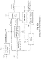
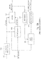
- the DirAC processing is performed in two phases: the analysis and the synthesis as pictured in Fig. 5a and 5b .
- a first-order coincident microphone in B-format is considered as input and the diffuseness and direction of arrival of the sound is analyzed in frequency domain.
- the DirAC synthesis stage shown in Fig. 5b sound is divided into two streams, the non-diffuse stream and the diffuse stream.
- the non-diffuse stream is reproduced as point sources using amplitude panning, which can be done by using vector base amplitude panning (VBAP) [2].
- VBAP vector base amplitude panning
- the diffuse stream is responsible of the sensation of envelopment and is produced by conveying to the loudspeakers mutually decorrelated signals.
- the analysis stage in Fig. 5a comprises a band filter 1000, an energy estimator 1001, an intensity estimator 1002, temporal averaging elements 999a and 999b, a diffuseness calculator 1003 and a direction calculator 1004.
- the calculated spatial parameters are a diffuseness value between 0 and 1 for each time/frequency tile and a direction of arrival parameter for each time/frequency tile generated by block 1004.
- the direction parameter comprises an azimuth angle and an elevation angle indicating the direction of arrival of a sound with respect to the reference or listening position and, particularly, with respect to the position, where the microphone is located, from which the four component signals input into the band filter 1000 are collected.
- These component signals are, in the Fig. 5a illustration, first order Ambisonics components which comprises an omnidirectional component W, a directional component X, another directional component Y and a further directional component Z.
- the DirAC synthesis stage illustrated in Fig. 5b comprises a band filter 1005 for generating a time/frequency representation of the B-format microphone signals W, X, Y, Z.
- the corresponding signals for the individual time/frequency tiles are input into a virtual microphone stage 1006 that generates, for each channel, a virtual microphone signal.
- a virtual microphone is directed in the direction of the center channel and the resulting signal is the corresponding component signal for the center channel.
- the signal is then processed via a direct signal branch 1015 and a diffuse signal branch 1014.
- Both branches comprise corresponding gain adjusters or amplifiers that are controlled by diffuseness values derived from the original diffuseness parameter in blocks 1007, 1008 and furthermore processed in blocks 1009, 1010 in order to obtain a certain microphone compensation.
- the component signal in the direct signal branch 1015 is also gain-adjusted using a gain parameter derived from the direction parameter consisting of an azimuth angle and an elevation angle. Particularly, these angles are input into a VBAP (vector base amplitude panning) gain table 1011. The result is input into a loudspeaker gain averaging stage 1012, for each channel, and a further normalizer 1013 and the resulting gain parameter is then forwarded to the amplifier or gain adjuster in the direct signal branch 1015.
- VBAP vector base amplitude panning
- the diffuse signal generated at the output of a decorrelator 1016 and the direct signal or non-diffuse stream are combined in a combiner 1017 and, then, the other subbands are added in another combiner 1018 which can, for example, be a synthesis filter bank.
- a loudspeaker signal for a certain loudspeaker is generated and the same procedure is performed for the other channels for the other loudspeakers 1019 in a certain loudspeaker setup.
- the high-quality version of DirAC synthesis is illustrated in Fig. 5b , where the synthesizer receives all B-format signals, from which a virtual microphone signal is computed for each loudspeaker direction.
- the utilized directional pattern is typically a dipole.
- the virtual microphone signals are then modified in non-linear fashion depending on the metadata as discussed with respect to the branches 1016 and 1015.
- the low-bit-rate version of DirAC is not shown in Fig. 5b . However, in this low-bit-rate version, only a single channel of audio is transmitted. The difference in processing is that all virtual microphone signals would be replaced by this single channel of audio received.
- the virtual microphone signals are divided into two streams, the diffuse and non-diffuse streams, which are processed separately.
- the non-diffuse sound is reproduced as point sources by using vector base amplitude panning (VBAP).
- panning a monophonic sound signal is applied to a subset of loudspeakers after multiplication with loudspeaker-specific gain factors.
- the gain factors are computed using the information of loudspeakers setup and specified panning direction.
- the input signal is simply panned to the directions implied by the metadata.
- each virtual microphone signal is multiplied with the corresponding gain factor, which produces the same effect with panning, however, it is less prone to any non-linear artifacts.
- the aim of the synthesis of the diffuse sound is to create perception of sound that surrounds the listener.
- the diffuse stream is reproduced by decorrelating the input signal and reproducing it from every loudspeaker.
- the virtual microphone signals of the diffuse streams are already incoherent in some degree, and they need to be decorrelated only mildly.
- the DirAC parameters also called spatial metadata consist of tuples of diffuseness and direction, which in spherical coordinate is represented by two angles, the azimuth and the elevation. If both analysis and synthesis stage are run at the decoder side the time-frequency resolution of the DirAC parameters can be chosen to be the same as the filter bank used for the DirAC analysis and synthesis, i.e. a distinct parameter set for every time slot and frequency bin of the filter bank representation of the audio signal.
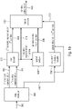
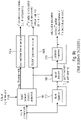
- FIG. 3 illustrates a system overview of an encoder and a decoder combining DirAC spatial sound processing with an audio coder.
- An input signal such as a multi-channel input signal, a first order Ambisonics (FOA) or a high order Ambisonics (HOA) signal or an object-encoded signal comprising of one or more transport signals comprising a downmix of objects and corresponding object metadata such as energy metadata and/or correlation data are input into a format converter and combiner 900.
- FOA first order Ambisonics
- HOA high order Ambisonics
- the format converter and combiner is configured to convert each of the input signals into a corresponding B-format signal and the format converter and combiner 900 additionally combines streams received in different representations by adding the corresponding B-format components together or by other combining technologies consisting of a weighted addition or a selection of different information of the different input data.
- the resulting B-format signal is introduced into a DirAC analyzer 210 in order to derive DirAC metadata such as direction of arrival metadata and diffuseness metadata, and the obtained signals are encoded using a spatial metadata encoder 220. Moreover, the B-format signal is forwarded to a beam former/signal selector in order to downmix the B-format signals into a transport channel or several transport channels that are then encoded using an EVS based core encoder 140.
- the output of block 220 on the one hand and block 140 on the other hand represent an encoded audio scene.
- the encoded audio scene is forwarded to a decoder, and in the decoder, a spatial metadata decoder 700 receives the encoded spatial metadata and an EVS-based core decoder 500 receives the encoded transport channels.
- the decoded spatial metadata obtained by block 700 is forwarded to a DirAC synthesis stage 800 and the decoded one or more transport channels at the output of block 500 are subjected to a frequency analysis in block 860.
- the resulting time/frequency decomposition is also forwarded to the DirAC synthesizer 800 that then generates, for example, as a decoded audio scene, loudspeaker signals or first order Ambisonics or higher order Ambisonics components or any other representation of an audio scene.
- the DirAC metadata i.e., the spatial parameters
- the decoder where they are used to reconstruct the 3D audio scene together with a lower dimensional representation of the audio signal.
- the DirAC metadata i.e. the spatial parameters
- the DirAC metadata are estimated and coded at a low bit rate and transmitted to the decoder where they are used to reconstruct the 3D audio scene together with a lower dimensional representation of the audio signal.
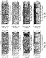
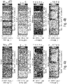
- FIGS 4a and 4b show a comparison between the uncoded and ungrouped spatial parameters of a DirAC analysis (a) and the coded and grouped parameters of the same signal using the DirAC spatial audio coding system disclosed in [3] with coded and transmitted DirAC metadata.
- the parameters used in the decoder (b) are closer to the parameters estimated from the original signal, but that the time-frequency-resolution is lower than for the decoder-only estimation.
- US 2017/365264 A1 discloses multichannel audio encoder and decoder based on a multimode core encoder/decoder (linear prediction coding and transform coding) which are associated with respective multichannel/stereo coding tools (e.g. mid/side coding for transform coding and parametric stereo for ACELP/TCX).
- US 2017/164131 A1 discloses encoding and decoding method of Higher Order Amsiconic signal, wherein a reduced set of coefficient sequences is transmitted with a set of directional sub-band signals with corresponding directions.
- US 2015/356978 A1 discloses multichannel audio coding and sound field coding methods based on orthogonal transformation (KLT) of the audio signals.
- KLT orthogonal transformation
- US 2007/019813 A1 discloses a hybrid coder mixing spatial audio coding with matrixed surround allowing a dynamic tradeoff between coding quality and bit-rate; the transmitted frequency bands are divided into a high-quality band, that is decoded with spatial audio coding, and a low-quality band, that is decoded with matrixed surround; the frequency ranges are depending on available transmission bit-rate and/or quality demands.
- an audio scene encoder of claim 1 an audio scene decoder of claim 15, a method of encoding an audio scene of claim 35, a method of decoding an audio scene of claim 36, a computer program of claim 37 or an encoded audio scene of claim 38.
- the present invention is based on the finding that an improved audio quality and a higher flexibility and, in general, an improved performance is obtained by applying a hybrid encoding/decoding scheme, where the spatial parameters used to generate a decoded two dimensional or three dimensional audio scene in the decoder are estimated in the decoder based on a coded transmitted and decoded typically lower dimensional audio representation for some parts of a time-frequency representation of the scheme, and are estimated, quantized and coded for other parts within the encoder and transmitted to the decoder.
- the division between the division between encoder-side estimated and decoder-side estimated regions can be diverging for different spatial parameters used in the generation of the three dimensional or two dimensional audio scene in the decoder.
- this partition into different portions or preferably time/frequency regions can be arbitrary. In a preferred embodiment, however, it is advantageous to estimate the parameters in the decoder for parts of the spectrum that are mainly coded in a wave-form-preserving manner, while coding and transmitting encoder-calculated parameters for parts of the spectrum where parametric coding tools were mainly used.
- Embodiments of the present invention aim to propose a low bit-rate coding solution for transmitting a 3D audio scene by employing a hybrid coding system where spatial parameters used for the reconstruction of the 3D audio scene are for some parts estimated and coded in the encoder and transmitted to the decoder, and for the remaining parts estimated directly in the decoder.
- the present invention discloses a 3D audio reproduction based on a hybrid approach for a decoder only parameter estimation for parts of a signal where the spatial cues are retained well after bringing the spatial representation into a lower dimension in an audio encoder and encoding the lower dimension representation and estimating in the encoder, coding in the encoder, and transmitting the spatial cues and parameters from the encoder to the decoder for parts of the spectrum where the lower dimensionality together with the coding of the lower dimensional representation would lead to a sub-optimal estimation of the spatial parameters.
- an audio scene encoder is configured for encoding an audio scene, the audio scene comprising at least two component signals
- the audio scene encoder comprises a core encoder configured for core encoding the at least two component signals, where the core encoder generates a first encoded representation for a first portion of the at least two component signals and generates a second encoded representation for a second portion of the at least two component signals.
- the spatial analyzer analyzes the audio scene to derive one or more spatial parameters or one or more spatial parameter sets for the second portion and an output interface then forms the encoded audio scene signal which comprises the first encoded representation, the second encoded representation and the one or more spatial parameters or one or more spatial parameter sets for the second portion.
- any spatial parameters for the first portion are not included in the encoded audio scene signal, since those spatial parameters are estimated from the decoded first representation in a decoder.
- the spatial parameters for the second portion are already calculated within the audio scene encoder based on the original audio scene or an already processed audio scene which has been reduced with respect to its dimension and, therefore, with respect to its bitrate.
- the encoder-calculated parameters can carry a high quality parametric information, since these parameters are calculated in the encoder from data which is highly accurate, not affected by core encoder distortions and potentially even available in a very high dimension such as a signal which is derived from a high quality microphone array. Due to the fact that such very high quality parametric information is preserved, it is then possible to core encode the second portion with less accuracy or typically less resolution. Thus, by quite coarsely core encoding the second portion, bits can be saved which can, therefore, be given to the representation of the encoded spatial metadata. Bits saved by a quite coarse encoding of the second portion can also be invested into a high resolution encoding of the first portion of the at least two component signals.
- a high resolution or high quality encoding of the at least two component signals is useful, since, at the decoder-side, any parametric spatial data does not exist for the first portion, but is derived within the decoder by a spatial analysis.
- any bits that would, in the comparison case, be necessary for the encoded metadata can be saved and invested into the higher quality core encoding of the at least two component signals in the first portion.
- the separation of the audio scene into the first portion and into the second portion can be done in a highly flexible manner, for example, depending on bitrate requirements, audio quality requirements, processing requirements, i.e., whether more processing resources are available in the encoder or the decoder, and so on.
- the separation into the first and the second portion is done based on the core encoder functionalities.
- the separation with respect to the spatial parameters is performed in such a way that the non-parametrically encoded portions of the signal form the first portion and the parametrically encoded portions of the signal form the second portion.
- the parametrically encoded second portion which typically are the lower resolution encoded portion of the audio signal
- a more accurate representation of the spatial parameters is obtained while for the better encoded, i.e., high resolution encoded first portion, the high quality parameters are not so necessary, since quite high quality parameters can be estimated on the decoder-side using the decoded representation of the first portion.
- the spatial parameters for the second portion are calculated, within the encoder, in a certain time/frequency resolution which can be a high time/frequency resolution or a low time/frequency resolution.
- the calculated parameters are then grouped in a certain way in order to obtain low time/frequency resolution spatial parameters.
- These low time/frequency resolution spatial parameters are nevertheless high quality spatial parameters that only have a low resolution.
- the low resolution is useful in that bits are saved for the transmission, since the number of spatial parameters for a certain time length and a certain frequency band are reduced. This reduction, however, is typically not so problematic, since the spatial data nevertheless does not change too much over time and, over frequency.
- a low bitrate but nevertheless good quality representation of the spatial parameters for the second portion can be obtained.
- the spatial parameters for the first portion are calculated on the decoder-side and do not have to be transmitted anymore, any compromises with respect to resolution do not have to be performed. Therefore, a high time and high frequency resolution estimation of spatial parameters can be performed on the decoder-side and this high resolution parametric data then helps in providing a nevertheless good spatial representation of the first portion of the audio scene.
- the "disadvantage" of calculating the spatial parameters on the decoder-side based on the at least two transmitted components for the first portion can be reduced or even eliminated by calculating high time and frequency resolution spatial parameters and by using these parameters in the spatial rendering of the audio scene. This does not incur any penalty in a bit rate, since any processing performed on the decoder-side does not have any negative influence on the transmitted bitrate in an encoder/decoder scenario.
- a further embodiment of the present invention relies on a situation, where, for the first portion, at least two components are encoded and transmitted so that, based on the at least two components, a parametric data estimation can be performed on the decoder-side.
- the second portion of the audio scene can even be encoded with a substantially lower bitrate, since it is preferred to only encode a single transport channel for the second representation.
- This transport or downmix channel is represented by a very low bitrate compared to the first portion, since, in the second portion, only a single channel or component is to be encoded while, in the first portion, two or more components are necessary to be encoded so that enough data for a decoder-side spatial analysis is there.
- the present invention provides additional flexibility with respect to bitrate, audio quality, and processing requirements available on the encoder or the decoder-side.
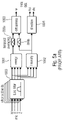
- Fig. 1a illustrates an audio scene encoder for encoding an audio scene 110 that comprises at least two component signals.
- the audio scene encoder comprises a core encoder 100 for core encoding the at least two component signals.
- the core encoder 100 is configured to generate a first encoded representation 310 for a first portion of the at least two component signals and to generate a second encoded representation 320 for a second portion of the at least two component signals.
- the audio scene encoder comprises a spatial analyzer for analyzing the audio scene to derive one or more spatial parameters or one or more spatial parameter sets for the second portion.
- the audio scene encoder comprises an output interface 300 for forming an encoded audio scene signal 340.
- the encoded audio scene signal 340 comprises the first encoded representation 310 representing the first portion of the at least two component signals, the second encoder representation 320 and parameters 330 for the second portion.
- the spatial analyzer 200 is configured to apply the spatial analysis for the first portion of the at least two component signals using the original audio scene 110. Alternatively, the spatial analysis can also be performed based on a reduced dimension representation of the audio scene. If, for example, the audio scene 110 comprises, for example, a recording of several microphones arranged in a microphone array, then the spatial analysis 200 can, of course, be performed based on this data. However, the core encoder 100 would then be configured to reduce the dimensionality of the audio scene to, for example, a first order Ambisonics representation or a higher order Ambisonics representation.
- the core encoder 100 would reduce the dimensionality to at least two components consisting of, for example, an omnidirectional component and at least one directional component such as X, Y, or Z of a B-format representation.
- an omnidirectional component and at least one directional component such as X, Y, or Z of a B-format representation.
- other representations such as higher order representations or an A-format representations are useful as well.
- the first encoder representation for the first portion would then consist of at least two different components being decodable and will typically, consist of an encoded audio signal for each component.
- the second encoder representation for the second portion can consist of the same number of components or can, alternatively, have a lower number such as only a single omnidirectional component that has been encoded by the core coder in a second portion.
- the core encoder 100 reduces the dimensionality of the original audio scene 110
- the reduced dimensionality audio scene optionally can be forwarded to the spatial analyzer via line 120 instead of the original audio scene.
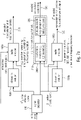
- Fig. 1b illustrates an audio scene decoder comprising an input interface 400 for receiving an encoded audio scene signal 340.
- This encoded audio scene signal comprises the first encoded representation 410, the second encoded representation 420 and one or more spatial parameters for the second portion of the at least two component signals illustrated at 430.
- the encoded representation of the second portion can, once again, be an encoded single audio channel or can comprise two or more encoded audio channels, while the first encoded representation of the first portion comprises at least two different encoded audio signals.
- the different encoded audio signals in the first encoded representation or, if available, in the second encoded representation can be jointly coded signals such as a jointly coded stereo signal or are, alternatively, and even preferably, individually encoded mono audio signals.
- the encoded representation comprising the first encoded representation 410 for the first portion and the second encoded representation 420 for the second portion is input into a core decoder for decoding the first encoded representation and the second encoded representation to obtain a decoded representation of the at least two component signals representing an audio scene.
- the decoded representation comprises a first decoded representation for the first portion indicated at 810 and a second decoded representation for a second portion indicated at 820.
- the first decoded representation is forwarded to a spatial analyzer 600 for analyzing a portion of the decoded representation corresponding to the first portion of the at least two component signals to obtain one or more spatial parameters 840 for the first portion of the at least two component signals.
- the audio scene decoder also comprises a spatial rendered 800 for spatially rendering the decoded representation which comprises, in the Fig. 1b embodiment, the first decoded representation for the first portion 810 and the second decoded representation for the second portion 820.
- the spatial renderer 800 is configured to use, for the purpose of audio rendering, the parameters 840 derived from the spatial analyzer for the first portion and, for the second portion, parameters 830 that are derived from the encoded parameters via a parameter/metadata decoder 700.
- the parameter/metadata decoder 700 is not necessary and the one or more spatial parameters for the second portion of the at least two component signals are directly forwarded from the input interface 400, subsequent to a demultiplex or a certain processing operation, to the spatial renderer 800 as data 830.
- Fig. 6a illustrates a schematic representation of different typically overlapping time frames F 1 to F 4 .
- the core encoder 100 of Fig. 1a can be configured to form such subsequent time frames from the at least two component signals.
- a first time frame could be the first portion and the second time frame could be the second portion.
- the first portion could be the first time frame and the second portion could be another time frame, and switching between the first and the second portion could be performed over time.
- Fig. 6a illustrates overlapping time frames, non-overlapping time frames are useful as well.
- Fig. 6a illustrates time frames having equal lengths, the switching could be done with time frames that have different lengths.
- the time frame F 2 is, for example, smaller than the time frame F 1 , then this would result in an increased time resolution for the second time frame F 2 with respect to the first time frame F 1 .
- the second time frame F 2 with the increased resolution would preferably correspond to the first portion that is encoded with respect to its components, while the first time portion, i.e., the low resolution data would correspond to the second portion that is encoded with a lower resolution but the spatial parameters for the second portion would be calculated with any resolution necessary, since the whole audio scene is available at the encoder.
- Fig. 6b illustrates an alternative implementation where the spectrum of the at least two component signals is illustrated as having a certain number of bands B1, B2, ..., B6, ....
- the bands are separated in bands with different bandwidths that increase from lowest to highest center frequencies in order to have a perceptually motivated band division of the spectrum.
- the first portion of the at least two component signals could, for example, consist of the first four bands, for example, the second portion could consist of bands B5 and bands B6. This would match with a situation, where the core encoder performs a spectral band replication and where the crossover frequency between the non-parametrically encoded low frequency portion and the parametrically encoded high frequency portion would be the border between the band B4 and the band B5.
- the bands are arbitrarily selected in line with a signal analysis and, therefore, the first portion could, for example, consist of bands B1, B2, B4, B6 and the second portion could be B3, B5 and probably another higher frequency band.
- the bands are, as preferred and illustrated in Fig. 6b , typical scale factor bands that have an increasing bandwidth from lowest to highest frequencies, or whether the bands are equally sized bands.
- the borders between the first portion and the second portion do not necessarily have to coincide with scale factor bands that are typically used by a core encoder, but it is preferred to have the coincidence between a border between the first portion and the second portion and a border between a scale factor band and an adjacent scale factor band.
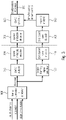
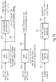
- Fig. 7a illustrates a preferred implementation of an audio scene encoder.
- the audio scene is input into a signal separator 140 that is preferably the portion of the core encoder 100 of Fig. 1a .
- the core encoder 100 of Fig. 1a comprises a dimension reducer 150a and 150b for both portions, i.e., the first portion of the audio scene and the second portion of the audio scene.
- At the output of the dimension reducer 150a there does exist at least two component signals that are then encoded in an audio encoder 160a for the first portion.
- the dimension reducer 150b for the second portion of the audio scene can comprise the same constellation as the dimension reducer 150a.
- the reduced dimension obtained by the dimension reducer 150b can be a single transport channel that is then encoded by the audio encoder 160b in order to obtain the second encoded representation 320 of at least one transport/component signal.
- the audio encoder 160a for the first encoded representation can comprise a wave form preserving or non-parametric or high time or high frequency resolution encoder while the audio encoder 160b can be a parametric encoder such as an SBR encoder, an IGF encoder, a noise filling encoder, or any low time or frequency resolution or so.
- the audio encoder 160b will typically result in a lower quality output representation compared to the audio encoder 160a.
- This "disadvantage" is addressed by performing a spatial analysis via the spatial data analyzer 210 of the original audio scene or, alternatively, a dimension reduced audio scene when the dimension reduced audio scene still comprises at least two component signals.
- the spatial data obtained by the spatial data analyzer 210 are then forwarded to a metadata encoder 220 that outputs an encoded low resolution spatial data.
- Both blocks 210, 220 are preferably included in the spatial analyzer block 200 of Fig. 1a .
- the spatial data analyzer performs a spatial data analysis with a high resolution such as a high frequency resolution or a high time resolution and, the, in order to keep the necessary bitrate for the encoded metadata in a reasonable range, the high resolution spatial data are preferably grouped and entropy encoded by the metadata encoder in order to have an encoded low resolution spatial data.
- a spatial data analysis is performed for, for example, eight time slots per frame and ten bands per time slot, one could group the spatial data into a single spatial parameter per frame and, for example, five bands per parameter.
- the metadata encoder 220 could then be configured to output the encoded data with different time/frequency resolutions for the directional and diffuseness data.
- directional data is required with a higher resolution than diffuseness data.
- a preferred way in order to calculate the parametric data with different resolutions is to perform the spatial analysis with a high resolution for and typically an equal resolution for both parametric kinds and to then perform a grouping in time and/or frequency with the different parametric information for the different parameter kinds in different ways in order to then have an encoded low resolution spatial data output 330 that has, for example, a medium resolution with time and/or frequency for the directional data and a low resolution for the diffuseness data.
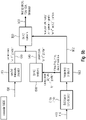
- Fig. 7b illustrates a corresponding decoder-side implementation of the audio scene decoder.
- the core decoder 500 of Fig. 1b comprises, in the Fig. 7b embodiment, a first audio decoder instance 510a and a second audio decoder instance 510b.
- the first audio decoder instance 510a is a non-parametric or wave form preserving or high resolution (in time and/or frequency) encoder that generates, at the output, a decoded first portion of the at least two component signals.
- This data 810 is, on the one hand, forwarded to the spatial renderer 800 of Fig. 1b and is, additionally input into a spatial analyzer 600.
- the spatial analyzer 600 is a high resolution spatial analyzer that calculates preferably high resolution spatial parameters for the first portion.
- the resolution of the spatial parameters for the first portion is higher than the resolution that is associated with the encoded parameters that are input into the parameter/metadata decoder 700.
- the entropy decoded low time or frequency resolution spatial parameters output by block 700 are input into a parameter de-grouper for resolution enhancement 710.
- Such a parameter de-grouping can be performed by copying a transmitted parameter to certain time/frequency tiles, where the de-grouping is performed in line with the corresponding grouping performed in the encoder-side metadata encoder 220 of Fig. 7a .
- further processing or smoothing operations can be performed as necessary.
- the result of block 710 is then a collection of decoded preferably high resolution parameters for the second portion that typically have the same resolution than the parameters 840 for the first portion. Also, the encoded representation of the second portion is decoded by the audio decoder 510b to obtain the decoded second portion 820 of typically at least one or of a signal having at least two components.
- Fig. 8a illustrates a preferred implementation of an encoder relying on the functionalities discussed with respect to Fig. 3 .
- multi-channel input data or first order Ambisonics or high order Ambisonics input data or object data is input into a B-format converter that converts and combines individual input data in order to generate, for example, typically four B-format components such as an omnidirectional audio signal and three directional audio signals such as X, Y and Z.
- the signal input into the format converter or the core encoder could be a signal captured by an omnidirectional microphone positioned at the first portion and another signal captured by an omnidirectional microphone positioned at the second portion different from the first portion.
- the audio scene comprises, as a first component signal, a signal captured by a directional microphone directed to a first direction and, as a second component, at least one signal captured by another directional microphone directed to a second direction different from the first direction.
- These "directional microphones" do not necessarily have to be real microphones but can also be virtual microphones.
- the audio input into block 900 or output by block 900 or generally used as the audio scene can comprise A-format component signals, B-format component signals, first order Ambisonics component signals, higher order Ambisonics component signals or component signals captured by a microphone array with at least two microphone capsules or component signals calculated from a virtual microphone processing.
- the output interface 300 of Fig. 1a is configured to not include any spatial parameters from the same parameter kind as the one or more spatial parameters generated by the spatial analyzer for the second portion into the encoded audio scene signal.
- the first encoded representation for the first portion will not comprise directional of arrival data and diffuseness data but can, of course, comprise any other parameters that have been calculated by the core encoder such as scale factors, LPC coefficients, etc.
- the band separation performed by signal separator 140 when the different portions are different bands can be implemented in such a way that a start band for the second portion is lower than the bandwidth extension start band and, additionally, the core noise filling does not necessarily have to apply any fixed crossover band, but can be used gradually for more parts of the core spectra as the frequency increases.
- the parametric or largely parametric processing for the second frequency subband of a time frame comprises calculating an amplitude-related parameter for the second frequency band and the quantization and entropy coding of this amplitude-related parameter instead of individual spectral lines in the second frequency subband.
- an amplitude related parameter forming a low resolution representation of the second portion is, for example, given by a spectral envelope representation having only, for example, one scale factor or energy value for each scale factor band, while the high resolution first portion relies on individual MDCT or FFT or general, individual spectral lines.
- a first portion of the at least two component signals is given by a certain frequency band for each component signal, and the certain frequency band for each component signal is encoded with a number of spectral lines to obtain the encoded representation of the first portion.
- an amplitude-related measure such as the sum of the individual spectral lines for the second portion or a sum of squared spectral lines representing an energy in the second portion or the sum of spectral lines raised to the power of three representing a loudness measure for the spectral portion can be used as well for the parametric encoded representation of the second portion.
- the core encoder 160 comprising of the individual core encoder branches 160a, 160b may comprise a beamforming/signal selection procedure for the second portion.
- the core encoder indicated at 160a, 160b in Fig. 8b outputs, on the one hand, an encoded first portion of all four B-format components and an encoded second portion of a single transport channel and spatial metadata for the second portion that have been generated by a DirAC analysis 210 relying on the second portion and a subsequently connected spatial metadata encoder 220.
- the encoded spatial metadata is input into the spatial metadata decoder 700 to generate the parameters for the second portion illustrated at 830.
- the core decoder which is a preferred embodiment typically implemented as an EVS-based core decoder consisting of elements 510a, 510b outputs the decoded representation consisting of both portions where, however, both portions are not yet separated.
- the decoded representation is input into a frequency analyzing block 860 and the frequency analyzer 860 generates the component signals for the first portion and forwards same to a DirAC analyzer 600 to generate the parameters 840 for the first portion.
- the transport channel/component signals for the first and the second portions are forwarded from the frequency analyzer 860 to the DirAC synthesizer 800.
- the DirAC synthesizer operates, in an embodiment, as usual, since the DirAC synthesizer does not have any knowledge and actually does not require any specific knowledge, whether the parameters for the first portion and the second portion have been derived on the encoder side or on the decoder side. Instead, both parameters "do the same" for the DirAC synthesizer 800 and the DirAC synthesizer can then generate, based on the frequency representation of the decoded representation of the at least two component signals representing the audio scene indicated at 862 and the parameters for both portions, a loudspeaker output, a first order Ambisonics (FOA), a high order Ambisonics (HOA) or a binaural output.
- FOA first order Ambisonics
- HOA high order Ambisonics
- Fig. 9a illustrates another preferred embodiment of an audio scene encoder, where the core encoder 100 of Fig. 1a is implemented as a frequency domain encoder.
- the signal to be encoded by the core encoder is input into an analysis filter bank 164 preferably applying a time-spectral conversion or decomposition with typically overlapping time frames.
- the core encoder comprises a wave form preserving encoder processor 160a and a parametric encoder processor 160b.
- the distribution of the spectral portions into the first portion and the second portion is controlled by a mode controller 166.
- the mode controller 166 can rely on a signal analysis, a bitrate control or can apply a fixed setting.
- the audio scene encoder can be configured to operate at different bitrates, wherein a predetermined border frequency between the first portion and the second portion depends on a selected bitrate, and wherein a predetermined border frequency is lower for a lower bitrate or greater for a greater bitrate.
- the mode controller can comprise a tonality mask processing as known from intelligent gap filling that analyzes the spectrum of the input signal in order to determine bands that have to be encoded with a high spectral resolution that end up in the encoded first portion and to determine bands that can be encoded in a parametric way that will then end up in the second portion.
- the mode controller 166 is configured to also control the spatial analyzer 200 on the encoder-side and preferably to control a band separator 230 of the spatial analyzer or a parameter separator 240 of the spatial analyzer. This makes sure that, in the end, only spatial parameters for the second portion, but not for the first portion are generated and output into the encoded scene signal.
- the spatial analyzer 200 calculates a full analysis over the first and the second portion and, the parameter separator 240 then only selects for output into the encoded scene signal the parameters for the second portion.
- the spatial analyzer 200 receives input data from a band separator, then the band separator 230 already forwards only the second portion and, then, a parameter separator 240 is not required anymore, since the spatial analyzer 200 anyway only receives the second portion and, therefore, only outputs the spatial data for the second portion.
- a selection of the second portion can be performed before or after the spatial analysis and is preferably controlled by the mode controller 166 or can also be implemented in a fixed manner.
- the spatial analyzer 200 relies on an analysis filter bank of the encoder or uses his own separate filter bank that is not illustrated in Fig. 9a , but that is illustrated, for example, in Fig. 5a for the DirAC analysis stage implementation indicated at 1000.
- Fig. 9b illustrates, in contrast to the frequency domain encoder of Fig. 9a , a time domain encoder.
- a band separator 168 is provided that is either controlled by a mode controller 166 of Fig. 9a (not illustrated in Fig. 9b ) or that is fixed. In case of a control, the control can be performed based on a bit rate, a signal analysis, or any other procedure useful for this purposed.
- the typically M components that are input into the band separator 168 are processed, on the one hand, by a low band time domain encoder 160a and, on the other hand, by a time domain bandwidth extension parameter calculator 160b.
- the low band time domain encoder 160a outputs the first encoded representation with the M individual components being in an encoded form.
- the second encoded representation generated by the time domain bandwidth extension parameter calculator 160b only has N components/transport signals, where the number N is smaller than the number M, and where N is greater than or equal to 1.
- a separate band separator 230 is not required.
- the spatial analyzer 200 relies on the band separator 230, then the connection between block 168 and block 200 of Fig. 9b is not necessary.
- the spatial analyzer performs a full band analysis and the parameter separator 240 then separates only the spatial parameters for the second portion that are then forwarded to the output interface or the encoded audio scene.
- Fig. 9a illustrates a wave form preserving encoder processor 160a or a spectral encoder for quantizing an entropy coding
- the corresponding block 160a in Fig. 9b is any time domain encoder such as an EVS encoder, an ACELP encoder, an AMR encoder or a similar encoder.
- block 160b illustrates a frequency domain parametric encoder or general parametric encoder
- the block 160b in Fig. 9b is a time domain bandwidth extension parameter calculator that can, basically, calculate the same parameters as block 160 or different parameters as the case may be.
- Fig. 10a illustrates a frequency domain decoder typically matching with the frequency domain encoder of Fig. 9a .
- the spectral decoder receiving the encoded first portion comprises, as illustrated at 160a, an entropy decoder, a dequantizer and any other elements that are, for example, known from AAC encoding or any other spectral domain encoding.
- the parametric decoder 160b that receives the parametric data such as energy per band as the second encoded representation for the second portion operates, typically, as an SBR decoder, an IGF decoder, a noise filling decoder or other parametric decoders.
- Both portions i.e., the spectral values of the first portion and the spectral values of the second portion are input into a synthesis filter bank 169 in order to have the decoded representation that is, typically forwarded to the spatial renderer for the purpose of spatially rendering the decoded representation.
- the first portion can be directly forwarded to the spatial analyzer 600 or the first portion can be derived from the decoded representation at the output of the synthesis filter bank 169 via a band separator 630.
- the parameter separator 640 is required or not. In case of the spatial analyzer 600 receiving the first portion only, then the band separator 630 and the parameter separator 640 are not required. In case of the spatial analyzer 600 receiving the decoded representation and the band separator is not there, then the parameter separator 640 is required. In case of the decoded representation is input into the band separator 630, then the spatial analyzer does not need to have the parameter separator 640, since the spatial analyzer 600 then only outputs the spatial parameters for the first portion.
- Fig. 10b illustrates a time domain decoder that is matching with the time domain encoder of Fig. 9b .
- the first encoded representation 410 is input into a low band time domain decoder 160a and the decoded first portion is input into a combiner 167.
- the bandwidth extension parameters 420 are input into a time domain bandwidth extension processor that outputs the second portion.
- the second portion is also input into the combiner 167.
- the combiner can be implemented to combine spectral values, when the first and the second portion are spectral values or can combine time domain samples when the first and the second portion are already available as time domain samples.
- the output of the combiner 167 is the decoded representation that can be processed, similar to what has been discussed before with respect to Fig. 10a , by the spatial analyzer 600 either with or without the band separator 630 or with or without the parameter separator 640 as the case may be.
- Fig. 11 illustrates a preferred implementation of the spatial renderer although other implementations of a spatial rendered that rely on DirAC parameters or on other parameters than DirAC parameters, or produce a different representation of the rendered signal than the direct loudspeaker representation, like a HOA representation, can be applied as well.
- the data 862 input into the DirAC synthesizer 800 can consist of several components such as the B-format for the first and the second portion as indicated at the upper left corner of Fig. 11 .
- the second portion is not available in several components but only has a single component. Then, the situation is as illustrated in the lower portion on the left of Fig. 11 .
- a full spectrum of all components is available and the time-frequency decomposition allows to perform a processing for each individual time/frequency tile.
- This processing is done by a virtual microphone processor 870a for calculating, for each loudspeaker of a loudspeaker setup, a loudspeaker component from the decoded representation.
- the time/frequency tiles for the first portion are input into the virtual microphone processor 870a, while the time/frequency portion for the single or lower number of components second portion is input into the processor 870b.
- the processor 870b for example, only has to perform a copying operation, i.e., to copy the single transport channel into an output signal for each loudspeaker signal.
- the virtual microphone processing 870a of the first alternative is replaced by a simply copying operation.
- the output of blocks 870a in the first embodiment or 870a for the first portion and 870b for the second portion are input into a gain processor 872 for modifying the output component signal using the one or more spatial parameters.
- the data is also input into a weighter/decorrelator processor 874 for generating a decorrelated output component signal using the one or more spatial parameters.
- the output of block 872 and the output of block 874 is combined within a combiner 876 operating for each component so that, at the output of block 876 one obtains a frequency domain representation of each loudspeaker signal.
- all frequency domain loudspeaker signals can be converted into a time domain representation and the generated time domain loudspeaker signals can be digital-to-analog converted and used to drive corresponding loudspeakers placed at the defined loudspeaker positions.
- the gain processor 872 operates based on spatial parameters and preferably, directional parameters such as the direction of arrival data and, optionally, based on diffuseness parameters. Additionally, the weighter/decorrelator processor operates based on spatial parameters as well, and, preferably, based on the diffuseness parameters.
- the gain processor 872 represents the generation of the non-diffuse stream in Fig. 5b illustrated at 1015
- the weighter/decorrelator processor 874 represents the generation of the diffuse stream as indicated by the upper branch 1014 of Fig. 5b , for example.
- the gain processor 872 represents the generation of the non-diffuse stream in Fig. 5b illustrated at 1015
- the weighter/decorrelator processor 874 represents the generation of the diffuse stream as indicated by the upper branch 1014 of Fig. 5b , for example.
- other implementations that rely on different procedures, different parameters and different ways for generating direct and diffuse signals can be implemented as well.
- An inventively encoded audio signal can be stored on a digital storage medium or a non-transitory storage medium or can be transmitted on a transmission medium such as a wireless transmission medium or a wired transmission medium such as the Internet.
- aspects have been described in the context of an apparatus, it is clear that these aspects also represent a description of the corresponding method, where a block or device corresponds to a method step or a feature of a method step. Analogously, aspects described in the context of a method step also represent a description of a corresponding block or item or feature of a corresponding apparatus.
- embodiments of the invention can be implemented in hardware or in software.
- the implementation can be performed using a digital storage medium, for example a floppy disk, a DVD, a CD, a ROM, a PROM, an EPROM, an EEPROM or a FLASH memory, having electronically readable control signals stored thereon, which cooperate (or are capable of cooperating) with a programmable computer system such that the respective method is performed.
- a digital storage medium for example a floppy disk, a DVD, a CD, a ROM, a PROM, an EPROM, an EEPROM or a FLASH memory, having electronically readable control signals stored thereon, which cooperate (or are capable of cooperating) with a programmable computer system such that the respective method is performed.
- Some embodiments according to the invention comprise a data carrier having electronically readable control signals, which are capable of cooperating with a programmable computer system, such that one of the methods described herein is performed.
- embodiments of the present invention can be implemented as a computer program product with a program code, the program code being operative for performing one of the methods when the computer program product runs on a computer.
- the program code may for example be stored on a machine readable carrier.
- inventions comprise the computer program for performing one of the methods described herein, stored on a machine readable carrier or a non-transitory storage medium.
- an embodiment of the inventive method is, therefore, a computer program having a program code for performing one of the methods described herein, when the computer program runs on a computer.
- a further embodiment of the inventive methods is, therefore, a data carrier (or a digital storage medium, or a computer-readable medium) comprising, recorded thereon, the computer program for performing one of the methods described herein.
- a further embodiment of the inventive method is, therefore, a data stream or a sequence of signals representing the computer program for performing one of the methods described herein.
- the data stream or the sequence of signals may for example be configured to be transferred via a data communication connection, for example via the Internet.
- a further embodiment comprises a processing means, for example a computer, or a programmable logic device, configured to or adapted to perform one of the methods described herein.
- a processing means for example a computer, or a programmable logic device, configured to or adapted to perform one of the methods described herein.
- a further embodiment comprises a computer having installed thereon the computer program for performing one of the methods described herein.
- a programmable logic device for example a field programmable gate array
- a field programmable gate array may cooperate with a microprocessor in order to perform one of the methods described herein.
- the methods are preferably performed by any hardware apparatus.
Landscapes
- Engineering & Computer Science (AREA)
- Physics & Mathematics (AREA)
- Acoustics & Sound (AREA)
- Signal Processing (AREA)
- Health & Medical Sciences (AREA)
- Audiology, Speech & Language Pathology (AREA)
- Computational Linguistics (AREA)
- Human Computer Interaction (AREA)
- Multimedia (AREA)
- Spectroscopy & Molecular Physics (AREA)
- Mathematical Physics (AREA)
- General Health & Medical Sciences (AREA)
- Otolaryngology (AREA)
- Stereophonic System (AREA)
- Compression, Expansion, Code Conversion, And Decoders (AREA)
Claims (38)
- , Audioszenencodierer zum Codieren einer Audioszene (110), wobei die Audioszene (110) zumindest zwei Komponentensignale aufweist, wobei der Audioszenencodierer Folgendes aufweist:einen Kerncodierer (160) zum Kerncodieren der zumindest zwei Komponentensignale, wobei der Kerncodierer (160) dazu konfiguriert ist, eine erste codierte Darstellung (310) für einen ersten Abschnitt der zumindest zwei Komponentensignale zu erzeugen und eine zweite codierte Darstellung (320) für einen zweiten Abschnitt der zumindest zwei Komponentensignale zu erzeugen,wobei der Kerncodierer (160) dazu konfiguriert ist, aus den zumindest zwei Komponentensignalen einen Zeitrahmen zu bilden, wobei ein erstes Frequenzteilband des Zeitrahmens der zumindest zwei Komponentensignale der erste Abschnitt der zumindest zwei Komponentensignale ist und ein zweites Frequenzteilband des Zeitrahmens der zweite Abschnitt der zumindest zwei Komponentensignale ist,wobei das erste Frequenzteilband von dem zweiten Frequenzteilband durch eine vorbestimmte Grenzfrequenz getrennt ist,wobei der Kerncodierer (160) dazu konfiguriert ist, die erste codierte Darstellung (310) für das erste Frequenzteilband, das M Komponentensignale aufweist, zu erzeugen und die zweite codierte Darstellung (320) für das zweite Frequenzteilband zu erzeugen, das N Komponentensignale aufweist, wobei M größer als N ist undwobei N größer oder gleich 1 ist;einen räumlichen Analysator (200) zum Analysieren der Audioszene (110), die die zumindest zwei Komponentensignale aufweist, um einen oder mehrere räumliche Parameter (330) oder einen oder mehrere Sätze von räumlichen Parametern für das zweite Frequenzteilband abzuleiten; undeine Ausgangsschnittstelle (300) zum Bilden eines codierten Audioszenensignals (340), wobei das codierte Audioszenensignal (340) die erste codierte Darstellung für das erste Frequenzteilband, das die M Komponentensignale aufweist, die zweite codierte Darstellung (320) für das zweite Frequenzteilband, das die N Komponentensignale aufweist, und den einen oder die mehreren räumlichen Parameter (330) oder einen oder mehrere Sätze von räumlichen Parametern für das zweite Frequenzteilband aufweist.
- , Audioszenencodierer gemäß Anspruch 1,wobei der Kerncodierer (160) dazu konfiguriert ist, die erste codierte Darstellung (310) mit einer ersten Frequenzauflösung zu erzeugen und die zweite codierte Darstellung (320) mit einer zweiten Frequenzauflösung zu erzeugen, wobei die zweite Frequenzauflösung niedriger als die erste Frequenzauflösung ist, oderwobei eine Grenzfrequenz zwischen dem ersten Frequenzteilband des Zeitrahmens und dem zweiten Frequenzteilband des Zeitrahmens mit einer Grenze zwischen einem Skalenfaktorband und einem benachbarten Skalenfaktorband übereinstimmt oder mit einer Grenze zwischen dem Skalenfaktorband und dem benachbarten Skalenfaktorband nicht übereinstimmt, wobei das Skalenfaktorband und das benachbarte Skalenfaktorband durch den Kerncodierer (160) verwendet werden.
- . Audioszenencodierer gemäß Anspruch 1 oder 2,wobei die Audioszene (110) als erstes Komponentensignal ein ungerichtetes Audiosignal und als zweites Komponentensignal zumindest ein gerichtetes Audiosignal aufweist oderwobei die Audioszene (110) als erstes Komponentensignal ein Signal, das durch ein ungerichtetes Mikrofon erfasst wird, das an einer ersten Position angeordnet ist, und als zweites Komponentensignal zumindest ein Signal aufweist, das durch ein ungerichtetes Mikrofon erfasst wird, das an einer zweiten Position angeordnet ist, die sich von der ersten Position unterscheidet, oderwobei die Audioszene (110) als erstes Komponentensignal zumindest ein Signal, das durch ein gerichtetes Mikrofon erfasst wird, das in eine erste Richtung gerichtet ist, und als zweites Komponentensignal zumindest ein Signal aufweist, das durch ein gerichtetes Mikrofon erfasst wird, das in eine zweite Richtung gerichtet ist, wobei sich die zweite Richtung von der ersten Richtung unterscheidet.
- . Audioszenencodierer gemäß einem der vorhergehenden Ansprüche,
wobei die Audioszene (110) A-Format-Komponentensignale, B-Format-Komponentensignale, First-Order-Ambisonics-Komponentensignale, Higher-Order-Ambisonics-Komponentensignale oder Komponentensignale aufweist, die durch ein Mikrofonarray mit zumindest zwei Mikrofonkapseln erfasst werden oder wie durch eine virtuelle Mikrofonberechnung aus einer zuvor aufgezeichneten oder synthetisierten Schallszene bestimmt sind. - . Audioszenencodierer gemäß einem der vorhergehenden Ansprüche,
wobei die Ausgangsschnittstelle (300) dazu konfiguriert ist, keine räumlichen Parameter von derselben Parameterart wie der eine oder die mehreren räumlichen Parameter (330), die durch den räumlichen Analysator (200) für das zweite Frequenzteilband erzeugt werden, in das codierte Audioszenensignal (340) einzuschließen, so dass lediglich das zweite Frequenzteilband die Parameterart aufweist, und keine Parameter der Parameterart für das erste Frequenzteilband in dem codierten Audioszenensignal (340) beinhaltet sind. - . Audioszenencodierer gemäß einem der vorhergehenden Ansprüche,wobei der Kerncodierer (160) dazu konfiguriert ist, einen parametrischen Codiervorgang (160b) für das zweite Frequenzteilband durchzuführen und einen wellenformerhaltenden Codiervorgang (160a) für das erste Frequenzteilband durchzuführen, oderwobei ein Startband für das zweite Frequenzteilband niedriger als ein Bandbreitenerweiterungs-Startband ist und wobei ein durch den Kerncodierer (100) durchgeführter Kernrauschfüllvorgang kein festes Übergangsband aufweist und schrittweise für mehr Teile von Kernspektren verwendet wird, während eine Frequenz zunimmt.
- . Audioszenencodierer gemäß einem der vorhergehenden Ansprüche,wobei der Kerncodierer (160) dazu konfiguriert ist, eine parametrische Verarbeitung (160b) für das zweite Frequenzteilband des Zeitrahmens durchzuführen, wobei die parametrische Verarbeitung (160b) ein Berechnen eines amplitudenbezogenen Parameters für das zweite Frequenzteilband und ein Quantisieren und Entropiecodieren des amplitudenbezogenen Parameters anstelle der einzelnen Spektrallinien in dem zweiten Frequenzteilband aufweist, und wobei der Kerncodierer (160) dazu konfiguriert ist, die einzelnen Spektrallinien in dem ersten Teilband des Zeitrahmens zu quantifizieren und einer Entropiecodierung (160a) zu unterziehen, oderwobei der Kerncodierer (160) dazu konfiguriert ist, eine parametrische Verarbeitung (160b) für ein Hochfrequenzteilband des Zeitrahmens durchzuführen, das dem zweiten Frequenzteilband der zumindest zwei Komponentensignale entspricht, wobei die parametrische Verarbeitung ein Berechnen eines amplitudenbezogenen Parameters für das Hochfrequenzteilband und ein Quantisieren und Entropiecodieren des amplitudenbezogenen Parameters anstelle eines Zeitbereichsignals in dem Hochfrequenzteilband aufweist, und wobei der Kerncodierer (160) dazu konfiguriert ist, das Zeitbereichaudiosignal in einem Niederfrequenzteilband des Zeitrahmens, das dem ersten Frequenzteilband der zumindest zwei Komponentensignale entspricht, durch einen Zeitbereichcodiervorgang wie LPC-Codierung, LPC/TCX-Codierung oder EVS-Codierung oder AMR-Wideband-Codierung oder AMR- Wideband+-Codierung zu quantisieren und einer Entropiecodierung (160b) zu unterziehen.
- . Audioszenencodierer gemäß Anspruch 7,
wobei die parametrische Verarbeitung (160b) eine Spektralbandreplikation(SBR)-Verarbeitung und eine intelligente Lückenfüll(IGF)-Verarbeitung oder eine Rauschfüllverarbeitung aufweist. - . Audioszenencodierer gemäß einem der vorhergehenden Ansprüche,
wobei der Kerncodierer (160) einen Dimensionsreduzierer (150a) zum Reduzieren einer Dimension der Audioszene (110) aufweist, um eine Audioszene mit niedrigerer Dimension zu erhalten, wobei der Kerncodierer (160) dazu konfiguriert ist, die erste codierte Darstellung (310) für das erste Frequenzteilband der zumindest zwei Komponentensignale aus der Audioszene mit der niedrigeren Dimension zu berechnen, und wobei der räumliche Analysator (200) dazu konfiguriert ist, die räumlichen Parameter (330) aus der Audioszene (110) abzuleiten, die eine Dimension aufweist, die größer als die Dimension der Audioszene mit der niedrigeren Dimension ist. - . Audioszenencodierer gemäß einem der vorhergehenden Ansprüche, der dazu konfiguriert ist, mit unterschiedlichen Bitraten zu arbeiten, wobei die vorbestimmte Grenzfrequenz zwischen dem ersten Frequenzteilband und dem zweiten Frequenzteilband von einer ausgewählten Bitrate abhängt, und wobei die vorbestimmte Grenzfrequenz für eine niedrigere Bitrate niedriger ist oder wobei die vorbestimmte Grenzfrequenz für eine höhere Bitrate höher ist.
- . Audioszenencodierer gemäß einem der vorhergehenden Ansprüche,
wobei der räumliche Analysator (200) dazu konfiguriert ist, für das zweite Teilband als den einen oder die mehreren räumlichen Parameter (330) zumindest einen eines Richtungsparameters und eines ungerichteten Parameters, beispielsweise einen Diffusionsparameter, zu berechnen. - . Audioszenencodierer gemäß einem der vorhergehenden Ansprüche, wobei der Kerncodierer (160) folgende Merkmale aufweist:einen Zeit-Frequenz-Wandler (164) zum Umwandeln von Zeitrahmensequenzen, die den Zeitrahmen der zumindest zwei Komponentensignale aufweisen, in Spektralrahmensequenzen für die zumindest zwei Komponentensignale,einen Spektralcodierer (160a) zum Quantisieren und Entropiecodieren von Spektralwerten eines Rahmens der Spektralrahmensequenzen in einem ersten Teilband des Spektralrahmens, das dem ersten Frequenzteilband entspricht; undeinen parametrischen Codierer (160b) zum parametrischen Entropiecodieren von Spektralwerten des Spektralrahmens in einem zweiten Teilband des Spektralrahmens, das dem zweiten Frequenzteilband entspricht, oderwobei der Kerncodierer (160) einen Zeitbereich- oder einen Gemischter-Zeitbereich-Frequenzbereich-Kerncodierer (160) zum Durchführen eines Zeitbereich- oder eines Gemischter-Zeitbereich-und-Frequenzbereich-Codiervorgangs eines Niederbandabschnitts des Zeitrahmens aufweist, wobei der Niederbandabschnitt dem ersten Frequenzteilband entspricht, oderwobei der räumliche Analysator (200) dazu konfiguriert ist, das zweite Frequenzteilband in Analysebänder zu unterteilen, wobei eine Bandbreite eines Analysebands größer als oder gleich einer Bandbreite ist, die zwei benachbarten Spektralwerten zugeordnet ist, die durch den Spektralcodierer in dem ersten Frequenzteilband verarbeitet werden, oder kleiner als eine Bandbreite eines Niederbandabschnitts ist, der das erste Frequenzteilband darstellt, und wobei der räumliche Analysator (200) dazu konfiguriert ist, zumindest einen eines Richtungsparameters und eines Diffusionsparameters für jedes Analyseband des zweiten Frequenzteilbands zu berechnen, oderwobei der Kerncodierer (160) und der räumliche Analysator (200) dazu konfiguriert sind, eine gemeinsame Filterbank (164) oder unterschiedliche Filterbänke (164, 1000) mit unterschiedlichen Charakteristika zu verwenden.
- . Audioszenencodierer gemäß Anspruch 12,
wobei der räumliche Analysator (200) dazu konfiguriert ist, zum Berechnen des Richtungsparameters ein Analyseband zu verwenden, das kleiner als ein Analyseband ist, das zum Berechnen des Diffusionsparameters verwendet wird. - . Audioszenencodierer gemäß einem der vorhergehenden Ansprüche,wobei der Kerncodierer (160) einen Mehrkanalcodierer zum Erzeugen eines codierten Mehrkanalsignals für die zumindest zwei Komponentensignale aufweist, oderwobei der Kerncodierer (160) einen Mehrkanalcodierer zum Erzeugen von zwei oder mehr codierten Mehrkanalsignalen aufweist, wenn eine Anzahl von Komponentensignalen der zumindest zwei Komponentensignale drei oder mehr beträgt, oderwobei die Ausgangsschnittstelle (300) dazu konfiguriert ist, keine räumlichen Parameter (330) für das erste Frequenzteilband in das codierte Audioszenensignal (340) einzuschließen oder eine kleinere Anzahl von räumlichen Parametern für das erste Frequenzteilband, verglichen mit einer Anzahl von räumlichen Parametern (330) für das zweite Frequenzteilband, in das codierte Audioszenensignal (340) einzuschließen.
- . Audioszenendecodierer, der folgende Merkmale aufweist:eine Eingangsschnittstelle (400) zum Empfangen eines codierten Audioszenensignals (340), das eine erste codierte Darstellung (410) eines ersten Abschnitts von zumindest zwei Komponentensignalen, eine zweite codierte Darstellung (420) eines zweiten Abschnitts der zumindest zwei Komponentensignale und einen oder mehrere räumliche Parameter (430) für den zweiten Abschnitt der zumindest zwei Komponentensignale aufweist;einen Kerndecodierer (500) zum Decodieren der ersten codierten Darstellung (410) und der zweiten codierten Darstellung (420), um eine decodierte Darstellung (810, 820) der zumindest zwei Komponentensignale zu erhalten, die eine Audioszene darstellen; undeinen räumlichen Analysator (600) zum Analysieren eines Abschnitts (810) der decodierten Darstellung, der dem ersten Abschnitt der zumindest zwei Komponentensignale entspricht, um einen oder mehrere räumliche Parameter (840) für den ersten Abschnitt der zumindest zwei Komponentensignale abzuleiten; undeine räumliche Aufbereitungsvorrichtung (800) zum räumlichen Aufbereiten der decodierten Darstellung (810, 820) unter Verwendung des einen oder der mehreren räumlichen Parameter (840) für den ersten Abschnitt und des einen oder der mehreren räumlichen Parameter (830) für den zweiten Abschnitt wie in dem codierten Audioszenensignal (340) beinhaltet.
- . Audioszenendecodierer gemäß Anspruch 15, der ferner folgendes Merkmal aufweist:einen Räumlicher-Parameter-Decodierer (700) zum Decodieren des einen oder der mehreren räumlichen Parameter (430) für den zweiten Abschnitt, die in dem codierten Audioszenensignal (340) beinhaltet sind, undwobei die räumliche Aufbereitungsvorrichtung (800) dazu konfiguriert ist, eine decodierte Darstellung des einen oder der mehreren räumlichen Parameter (830) zu verwenden, um den zweiten Teil der decodierten Darstellung der zumindest zwei Komponentensignale aufzubereiten.
- . Audioszenendecodierer gemäß Anspruch 15 oder Anspruch 16, wobei der Kerndecodierer (500) dazu konfiguriert ist, eine Sequenz von decodierten Rahmen bereitzustellen, wobei der erste Abschnitt ein erster Rahmen der Sequenz von decodierten Rahmen ist und der zweite Abschnitt ein zweiter Rahmen der Sequenz von decodierten Rahmen ist, und wobei der Kerndecodierer (500) ferner einen Überlappungsaddierer zum Überlappungsaddieren von aufeinanderfolgenden decodierten Zeitrahmen aufweist, um die decodierte Darstellung zu erhalten, oder
wobei der Kerndecodierer (500) ein ACELP-basiertes System aufweist, das ohne Überlappungsaddiervorgang arbeitet. - . Audioszenendecodierer gemäß einem der Ansprüche 15 bis 17,wobei der Kerndecodierer (500) dazu konfiguriert ist, eine Sequenz von decodierten Zeitrahmen bereitzustellen,wobei der erste Abschnitt ein erstes Teilband eines Zeitrahmens der Sequenz von decodierten Zeitrahmen ist und wobei der zweite Abschnitt ein zweites Teilband des Zeitrahmens der Sequenz von decodierten Zeitrahmen ist,wobei der räumliche Analysator (600) dazu konfiguriert ist, einen oder mehrere räumliche Parameter (840) für das erste Teilband bereitzustellen,wobei die räumliche Aufbereitungsvorrichtung (800) zu Folgendem konfiguriert ist:Aufbereiten des ersten Teilbands unter Verwendung des ersten Teilbands des Zeitrahmens und des einen oder der mehreren räumlichen Parameter (840) für das erste Teilband, undAufbereiten des zweiten Teilbands unter Verwendung des zweiten Teilbands des Zeitrahmens und des einen oder der mehreren räumlichen Parameter (830) für das zweite Teilband aufzubereiten.
- . Audioszenendecodierer gemäß Anspruch 18,
wobei die räumliche Aufbereitungsvorrichtung (800) einen Kombinierer zum Kombinieren eines ersten aufbereiteten Teilbands und eines zweiten aufbereiteten Teilbands aufweist, um einen Zeitrahmen eines aufbereiteten Signals zu erhalten. - . Audioszenendecodierer gemäß einem der Ansprüche 15 bis 19,
wobei die räumliche Aufbereitungsvorrichtung (800) dazu konfiguriert ist, ein aufbereitetes Signal für jeden Lautsprecher einer Lautsprecheranordnung oder für jede Komponente eines First-Order- oder Higher-Order-Ambisonics-Formats oder für jede Komponente eines binauralen Formats bereitzustellen. - . Audioszenendecodierer gemäß einem der Ansprüche 15 bis 20, wobei die räumliche Aufbereitungsvorrichtung (800) folgende Merkmale aufweist:einen Prozessor (870b) zum Erzeugen, für jede Ausgangskomponente, eines Ausgangskomponentensignals aus der decodierten Darstellung;einen Gewinnprozessor (872) zum Modifizieren des Ausgangskomponentensignals unter Verwendung des einen oder der mehreren räumlichen Parameter (830, 840); odereinen Gewichtungseinrichtungs-/Dekorrelatorprozessor (874) zum Erzeugen eines dekorrelierten Ausgangskomponentensignals unter Verwendung des einen oder der mehreren räumlichen Parameter (830, 840); undeinen Kombinierer (876) zum Kombinieren des dekorrelierten Ausgangskomponentensignals und des Ausgangskomponentensignals, um ein aufbereitetes Lautsprechersignal zu erhalten, oder
wobei die räumliche Aufbereitungsvorrichtung (800) folgende Merkmale aufweist:einen virtuellen Mikrofonprozessor (870a) zum Berechnen, für jeden Lautsprecher einer Lautsprecheranordnung, eines Lautsprecherkomponentensignals aus der decodierten Darstellung;einen Gewinnprozessor (872) zum Modifizieren des Lautsprecherkomponentensignals unter Verwendung des einen oder der mehreren räumlichen Parameter (830, 840); odereinen Gewichtungseinrichtungs-/Dekorrelatorprozessor (874) zum Erzeugen eines dekorrelierten Lautsprecherkomponentensignals unter Verwendung des einen oder der mehreren räumlichen Parameter (830, 840); undeinen Kombinierer (876) zum Kombinieren des dekorrelierten Lautsprecherkomponentensignals und des Lautsprecherkomponentensignals, um ein aufbereitetes Lautsprechersignal zu erhalten. - . Audioszenendecodierer gemäß einem der Ansprüche 15 bis 21, wobei die räumliche Aufbereitungsvorrichtung (800) dazu konfiguriert ist, bandweise zu arbeiten, wobei der erste Abschnitt ein erstes Teilband ist, wobei das erste Teilband in eine Mehrzahl von ersten Bändern unterteilt ist, wobei der zweite Abschnitt ein zweites Teilband ist, wobei das zweite Teilband in eine Mehrzahl von zweiten Bändern unterteilt ist,wobei die räumliche Aufbereitungsvorrichtung (800) dazu konfiguriert ist, ein Ausgangskomponentensignal für jedes erste Band unter Verwendung eines entsprechenden räumlichen Parameters aufzubereiten, der durch den Analysator abgeleitet wird, undwobei die räumliche Aufbereitungsvorrichtung (800) dazu konfiguriert ist, ein Ausgangskomponentensignal für jedes zweite Band unter Verwendung eines entsprechenden räumlichen Parameters aufzubereiten, der in dem codierten Audioszenensignal (340) beinhaltet ist, wobei ein zweites Band aus der Mehrzahl von zweiten Bändern größer als ein erstes Band aus der Mehrzahl von ersten Bändern ist, undwobei die räumliche Aufbereitungsvorrichtung (800) dazu konfiguriert ist, die Ausgangskomponentensignale für die ersten Bänder und die zweiten Bänder zu kombinieren (878), um ein aufbereitetes Ausgangssignal zu erhalten, wobei das aufbereitete Ausgangssignal ein Lautsprechersignal, ein A-Format-Signal, ein B-Format-Signal, ein First-Order-Ambisonics-Signal, ein Higher-Order-Ambisonics-Signal oder ein binaurales Signal ist.
- . Audioszenendecodierer gemäß einem der Ansprüche 15 bis 22,
wobei der Kerndecodierer (500) dazu konfiguriert ist, für die decodierte Darstellung, die die Audioszene darstellt, als erstes Komponentensignal ein ungerichtetes Audiosignal und als zweites Komponentensignal zumindest ein gerichtetes Audiosignal zu erzeugen, oder wobei die decodierte Darstellung, die die Audioszene darstellt, B-Format-Komponentensignale oder First-Order-Ambisonics-Komponentensignale oder Higher-Order-Ambisonics-Komponentensignale aufweist. - . Audioszenendecodierer gemäß einem der Ansprüche 15 bis 23,
wobei das codierte Audioszenensignal (340) keine räumlichen Parameter für den ersten Abschnitt der zumindest zwei Komponentensignale umfasst, die von derselben Art wie die räumlichen Parameter (430) für den zweiten Abschnitt sind, die in dem codierten Audioszenensignal (340) beinhaltet sind. - . Audioszenendecodierer gemäß einem der Ansprüche 15 bis 24,
wobei der Kerndecodierer (500) dazu konfiguriert ist, einen parametrischen Decodiervorgang (510b) für den zweiten Abschnitt durchzuführen und einen wellenformerhaltenden Decodiervorgang (510a) für den ersten Abschnitt durchzuführen. - . Audioszenendecodierer gemäß einem der Ansprüche 15 bis 25,wobei der Kerndecodierer (500) dazu konfiguriert ist, eine parametrische Verarbeitung (510b) unter Verwendung eines amplitudenbezogenen Parameters durchzuführen, um das zweite Teilband nach der Entropiedecodierung des amplitudenbezogenen Parameters einer Hüllkurveneinstellung zu unterziehen, undwobei der Kerndecodierer (500) dazu konfiguriert ist, einzelne Spektrallinien in dem ersten Teilband einer Entropiedecodierung zu unterziehen (510a).
- . Audioszenendecodierer gemäß einem der Ansprüche 15 bis 26,
wobei der Kerndecodierer (500) für die Decodierung (510b) der zweiten codierten Darstellung (420) eine Spektralbandreplikation (SBR)-Verarbeitung, eine intelligente Lückenfüll(IGF)-Verarbeitung oder eine Rauschfüllverarbeitung aufweist. - . Audioszenendecodierer gemäß einem der Ansprüche 15 bis 27, wobei der erste Abschnitt ein erstes Teilband eines Zeitrahmens ist und der zweite Abschnitt ein zweites Teilband des Zeitrahmens ist, und wobei der Kerndecodierer (500) dazu konfiguriert ist, eine vorbestimmte Grenzfrequenz zwischen dem ersten Teilband und dem zweiten Teilband zu verwenden.
- . Audioszenendecodierer gemäß einem der Ansprüche 15 bis 28, wobei der Audioszenendecodierer dazu konfiguriert ist, mit unterschiedlichen Bitraten zu arbeiten, wobei eine vorbestimmte Grenzfrequenz zwischen dem ersten Abschnitt und dem zweiten Abschnitt von einer ausgewählten Bitrate abhängt, und wobei die vorbestimmte Grenzfrequenz für eine niedrigere Bitrate niedriger ist oder wobei die vorbestimmte Grenzfrequenz für eine höhere Bitrate höher ist.
- . Audioszenendecodierer gemäß einem der Ansprüche 15 bis 29, wobei der erste Abschnitt ein erstes Teilband eines Zeitabschnitts ist, und wobei der zweite Abschnitt ein zweites Teilband eines Zeitabschnitts ist, und
wobei der räumliche Analysator (600) dazu konfiguriert ist, für das erste Teilband als den einen oder die mehreren räumlichen Parameter (840) zumindest einen eines Richtungsparameters und eines Diffusionsparameters zu berechnen. - . Audioszenendecodierer gemäß einem der Ansprüche 15 bis 30,wobei der erste Abschnitt ein erstes Teilband eines Zeitrahmens ist und wobei der zweite Abschnitt ein zweites Teilband eines Zeitrahmens ist,wobei der räumliche Analysator (600) dazu konfiguriert ist, das erste Teilband in Analysebänder zu unterteilen, wobei eine Bandbreite eines Analysebandes größer als oder gleich einer Bandbreite ist, die zwei benachbarten Spektralwerten zugeordnet ist, die durch den Kerndecodierer (500) für das erste Teilband erzeugt werden, undwobei der räumliche Analysator (600) dazu konfiguriert ist, zumindest einen des Richtungsparameters und des Diffusionsparameters für jedes Analyseband zu berechnen.
- . Audioszenendecodierer gemäß Anspruch 31,
wobei der räumliche Analysator (600) dazu konfiguriert ist, zum Berechnen des Richtungsparameters ein Analyseband zu verwenden, das kleiner als ein Analyseband ist, das zum Berechnen des Diffusionsparameters verwendet wird. - . Audioszenendecodierer gemäß einem der Ansprüche 15 bis 32,wobei der räumliche Analysator (600) dazu konfiguriert ist, zum Berechnen des Richtungsparameters ein Analyseband zu verwenden, das eine erste Bandbreite aufweist, undwobei die räumliche Aufbereitungsvorrichtung (800) dazu konfiguriert ist, einen räumlichen Parameter des einen oder der mehreren räumlichen Parameter (840) für den zweiten Abschnitt der zumindest zwei Komponentensignale zu verwenden, die in dem codierten Audioszenensignal (340) beinhaltet sind, um ein Aufbereitungsband der decodierten Darstellung aufzubereiten, wobei das Aufbereitungsband eine zweite Bandbreite aufweist, undwobei die zweite Bandbreite größer als die erste Bandbreite ist.
- . Audioszenendecodierer gemäß einem der Ansprüche 15 bis 33,wobei das codierte Audioszenensignal (340) ein codiertes Mehrkanalsignal für die zumindest zwei Komponentensignale aufweist oder wobei das codierte Audioszenensignal (340) zumindest zwei codierte Mehrkanalsignale für eine Anzahl von Komponentensignalen aufweist, die größer als 2 ist, undwobei der Kerndecodierer (500) einen Mehrkanaldecodierer zum Kerndecodieren des codierten Mehrkanalsignals oder der zumindest zwei codierten Mehrkanalsignale aufweist.
- . Verfahren zum Codieren einer Audioszene (110), wobei die Audioszene (110) zumindest zwei Komponentensignale aufweist, wobei das Verfahren folgende Schritte aufweist:Kerncodieren der zumindest zwei Komponentensignale, wobei das Kerncodieren ein Erzeugen einer ersten codierten Darstellung (310) für einen ersten Abschnitt der zumindest zwei Komponentensignale und ein Erzeugen einer zweiten codierten Darstellung (320) für einen zweiten Abschnitt der zumindest zwei Komponentensignale aufweist;wobei das Kerncodieren ein Bilden eines Zeitrahmens aus den zumindest zwei Komponentensignalen aufweist, wobei ein erstes Frequenzteilband des Zeitrahmens der zumindest zwei Komponentensignale der erste Abschnitt der zumindest zwei Komponentensignale ist und ein zweites Frequenzteilband des Zeitrahmens der zweite Abschnitt der zumindest zwei Komponentensignale ist, wobei das erste Frequenzteilband von dem zweiten Frequenzteilband durch eine vorbestimmte Grenzfrequenz getrennt ist,wobei das Kerncodieren ein Erzeugen der ersten codierten Darstellung (310) für das erste Frequenzteilband, das M Komponentensignale aufweist, und ein Erzeugen der zweiten codierten Darstellung (320) für das zweite Frequenzteilband aufweist, das N Komponentensignale aufweist, wobei M größer als N ist und wobei N größer als oder gleich 1 ist;Analysieren der Audioszene (110), die die zumindest zwei Komponentensignale aufweist, um einen oder mehrere räumliche Parameter (330) oder einen oder mehrere Sätze von räumlichen Parametern für das zweite Frequenzteilband abzuleiten; undBilden des codierten Audioszenensignals, wobei das codierte Audioszenensignal (340) die erste codierte Darstellung für das erste Frequenzteilband, das die M Komponentensignale aufweist, die zweite codierte Darstellung (320) für das zweite Frequenzteilband, das die N Komponentensignale aufweist, und den einen oder die mehreren räumlichen Parameter (330) oder den einen oder die mehreren Sätze von räumlichen Parametern für das zweite Frequenzteilband aufweist.
- . Verfahren zum Decodieren einer Audioszene, das folgende Schritte aufweist:Empfangen eines codierten Audioszenensignals (340), das eine erste codierte Darstellung (410) eines ersten Abschnitts von zumindest zwei Komponentensignalen, eine zweite codierte Darstellung (420) eines zweiten Abschnitts der zumindest zwei Komponentensignale und einen oder mehrere räumliche Parameter (430) für den zweiten Abschnitt der zumindest zwei Komponentensignale aufweist;Decodieren der ersten codierten Darstellung (410) und der zweiten codierten Darstellung (420), um eine decodierte Darstellung der zumindest zwei Komponentensignale zu erhalten, die die Audioszene darstellen;Analysieren eines Abschnitts der decodierten Darstellung, der dem ersten Abschnitt der zumindest zwei Komponentensignale entspricht, um einen oder mehrere räumliche Parameter (840) für den ersten Abschnitt der zumindest zwei Komponentensignale abzuleiten; undräumliches Aufbereiten der decodierten Darstellung unter Verwendung des einen oder der mehreren räumlichen Parameter (840) für den ersten Abschnitt und des einen oder der mehreren räumlichen Parameter (430) für den zweiten Abschnitt wie in dem codierten Audioszenensignal (340) beinhaltet.
- . Computerprogramm zum Durchführen des Verfahrens gemäß Anspruch 35 oder des Verfahrens gemäß Anspruch 36, wenn dasselbe auf einem Computer oder Prozessor abläuft.
- . Codiertes Audioszenensignal (340), das folgende Merkmale aufweist:eine erste codierte Darstellung für ein erstes Frequenzteilband eines Zeitrahmens von zumindest zwei Komponentensignalen einer Audioszene (110), wobei die erste codierte Darstellung (310) für das erste Frequenzteilband M Komponentensignale aufweist;eine zweite codierte Darstellung für ein zweites Frequenzteilband eines Zeitrahmens der zumindest zwei Komponentensignale einer Audioszene (110), wobei die erste codierte Darstellung (310) für das zweite Frequenzteilband M Komponentensignale aufweist;eine zweite codierte Darstellung (320) für ein zweites Frequenzteilband eines Zeitrahmens der zumindest zwei Komponentensignale, wobei die zweite codierte Darstellung (320) für das zweite Frequenzteilband N Komponentensignale aufweist,wobei M größer als N ist, wobei N größer als oder gleich 1 ist, wobei das erste Frequenzteilband von dem zweiten Frequenzteilband durch eine vorbestimmte Grenzfrequenz getrennt ist; undeinen oder mehrere räumliche Parameter (330) oder einen oder mehrere Sätze von räumlichen Parametern für das zweite Frequenzteilband.
Priority Applications (1)
| Application Number | Priority Date | Filing Date | Title |
|---|---|---|---|
| EP22171223.5A EP4057281A1 (de) | 2018-02-01 | 2019-01-31 | Audioszenencodierer, audioszenendecodierer und verwandte verfahren unter verwendung einer hybriden encoder-decoder-raumanalyse |
Applications Claiming Priority (3)
| Application Number | Priority Date | Filing Date | Title |
|---|---|---|---|
| EP18154749 | 2018-02-01 | ||
| EP18185852 | 2018-07-26 | ||
| PCT/EP2019/052428 WO2019149845A1 (en) | 2018-02-01 | 2019-01-31 | Audio scene encoder, audio scene decoder and related methods using hybrid encoder/decoder spatial analysis |
Related Child Applications (1)
| Application Number | Title | Priority Date | Filing Date |
|---|---|---|---|
| EP22171223.5A Division EP4057281A1 (de) | 2018-02-01 | 2019-01-31 | Audioszenencodierer, audioszenendecodierer und verwandte verfahren unter verwendung einer hybriden encoder-decoder-raumanalyse |
Publications (2)
| Publication Number | Publication Date |
|---|---|
| EP3724876A1 EP3724876A1 (de) | 2020-10-21 |
| EP3724876B1 true EP3724876B1 (de) | 2022-05-04 |
Family
ID=65276183
Family Applications (2)
| Application Number | Title | Priority Date | Filing Date |
|---|---|---|---|
| EP19702889.7A Active EP3724876B1 (de) | 2018-02-01 | 2019-01-31 | Audioszenencodierer, audioszenendecodierer und verwandte verfahren unter verwendung einer hybriden encoder-decoder-raumanalyse |
| EP22171223.5A Withdrawn EP4057281A1 (de) | 2018-02-01 | 2019-01-31 | Audioszenencodierer, audioszenendecodierer und verwandte verfahren unter verwendung einer hybriden encoder-decoder-raumanalyse |
Family Applications After (1)
| Application Number | Title | Priority Date | Filing Date |
|---|---|---|---|
| EP22171223.5A Withdrawn EP4057281A1 (de) | 2018-02-01 | 2019-01-31 | Audioszenencodierer, audioszenendecodierer und verwandte verfahren unter verwendung einer hybriden encoder-decoder-raumanalyse |
Country Status (16)
| Country | Link |
|---|---|
| US (3) | US11361778B2 (de) |
| EP (2) | EP3724876B1 (de) |
| JP (2) | JP7261807B2 (de) |
| KR (2) | KR20200116968A (de) |
| CN (2) | CN112074902B (de) |
| AU (1) | AU2019216363B2 (de) |
| BR (1) | BR112020015570A2 (de) |
| CA (1) | CA3089550C (de) |
| ES (1) | ES2922532T3 (de) |
| MX (1) | MX2020007820A (de) |
| PL (1) | PL3724876T3 (de) |
| RU (1) | RU2749349C1 (de) |
| SG (1) | SG11202007182UA (de) |
| TW (1) | TWI760593B (de) |
| WO (1) | WO2019149845A1 (de) |
| ZA (1) | ZA202004471B (de) |
Cited By (1)
| Publication number | Priority date | Publication date | Assignee | Title |
|---|---|---|---|---|
| WO2024209008A1 (en) | 2023-04-05 | 2024-10-10 | Fraunhofer-Gesellschaft zur Förderung der angewandten Forschung e.V. | Audio processor, audio processing system, audio decoder, method for providing a processed audio signal representation and computer program using a time scale modification |
Families Citing this family (17)
| Publication number | Priority date | Publication date | Assignee | Title |
|---|---|---|---|---|
| CN109547711A (zh) * | 2018-11-08 | 2019-03-29 | 北京微播视界科技有限公司 | 视频合成方法、装置、计算机设备及可读存储介质 |
| GB201914665D0 (en) * | 2019-10-10 | 2019-11-27 | Nokia Technologies Oy | Enhanced orientation signalling for immersive communications |
| GB2595871A (en) * | 2020-06-09 | 2021-12-15 | Nokia Technologies Oy | The reduction of spatial audio parameters |
| CN114067810B (zh) * | 2020-07-31 | 2025-12-12 | 华为技术有限公司 | 音频信号渲染方法和装置 |
| US12555589B2 (en) | 2020-12-02 | 2026-02-17 | Dolby Laboratories Licensing Corporation | Spatial noise filling in multi-channel codec |
| KR20220130450A (ko) | 2021-03-18 | 2022-09-27 | 삼성전자주식회사 | 음성 인식을 위한 인공 신경망에서의 디코딩 방법 및 디코딩 장치 |
| WO2022200666A1 (en) * | 2021-03-22 | 2022-09-29 | Nokia Technologies Oy | Combining spatial audio streams |
| WO2022262750A1 (zh) * | 2021-06-15 | 2022-12-22 | 北京字跳网络技术有限公司 | 音频渲染系统、方法和电子设备 |
| CN115497485B (zh) * | 2021-06-18 | 2024-10-18 | 华为技术有限公司 | 三维音频信号编码方法、装置、编码器和系统 |
| GB2608406A (en) * | 2021-06-30 | 2023-01-04 | Nokia Technologies Oy | Creating spatial audio stream from audio objects with spatial extent |
| CN115881140B (zh) * | 2021-09-29 | 2025-09-26 | 华为技术有限公司 | 编解码方法、装置、设备、存储介质及计算机程序产品 |
| CN115881138B (zh) * | 2021-09-29 | 2026-04-10 | 华为技术有限公司 | 解码方法、装置、设备、存储介质及计算机程序产品 |
| CN115881139B (zh) * | 2021-09-29 | 2026-04-28 | 华为技术有限公司 | 编解码方法、装置、设备、存储介质及计算机程序 |
| EP4738347A3 (de) * | 2021-11-30 | 2026-05-20 | Dolby International AB | Verfahren und vorrichtungen zur codierung oder decodierung von szenenbasiertem immersivem audioinhalt |
| WO2023234429A1 (ko) | 2022-05-30 | 2023-12-07 | 엘지전자 주식회사 | 인공 지능 기기 |
| GB2628636A (en) * | 2023-03-31 | 2024-10-02 | Nokia Technologies Oy | Spatial metadata direction harmonization |
| WO2025145384A1 (zh) * | 2024-01-04 | 2025-07-10 | 北京小米移动软件有限公司 | 编码和解码方法、设备及存储介质 |
Family Cites Families (25)
| Publication number | Priority date | Publication date | Assignee | Title |
|---|---|---|---|---|
| US4363122A (en) * | 1980-09-16 | 1982-12-07 | Northern Telecom Limited | Mitigation of noise signal contrast in a digital speech interpolation transmission system |
| US7983922B2 (en) * | 2005-04-15 | 2011-07-19 | Fraunhofer-Gesellschaft Zur Foerderung Der Angewandten Forschung E.V. | Apparatus and method for generating multi-channel synthesizer control signal and apparatus and method for multi-channel synthesizing |
| US20070055510A1 (en) | 2005-07-19 | 2007-03-08 | Johannes Hilpert | Concept for bridging the gap between parametric multi-channel audio coding and matrixed-surround multi-channel coding |
| US8160888B2 (en) * | 2005-07-19 | 2012-04-17 | Koninklijke Philips Electronics N.V | Generation of multi-channel audio signals |
| CN101689368B (zh) * | 2007-03-30 | 2012-08-22 | 韩国电子通信研究院 | 对具有多声道的多对象音频信号进行编码和解码的设备和方法 |
| KR101452722B1 (ko) * | 2008-02-19 | 2014-10-23 | 삼성전자주식회사 | 신호 부호화 및 복호화 방법 및 장치 |
| EP2306452B1 (de) * | 2008-07-29 | 2017-08-30 | Panasonic Intellectual Property Management Co., Ltd. | Tonkodierungs-/-dekodierungseinrichtung, verfahren und programm |
| EP2224433B1 (de) * | 2008-09-25 | 2020-05-27 | Lg Electronics Inc. | Vorrichtung zur Verarbeitung eines Audiosignals und Verfahren dafür |
| JP5214058B2 (ja) | 2009-03-17 | 2013-06-19 | ドルビー インターナショナル アーベー | 適応的に選択可能な左/右又はミッド/サイド・ステレオ符号化及びパラメトリック・ステレオ符号化の組み合わせに基づいた高度ステレオ符号化 |
| EP2375410B1 (de) * | 2010-03-29 | 2017-11-22 | Fraunhofer-Gesellschaft zur Förderung der angewandten Forschung e.V. | Räumlicher Audioprozessor und Verfahren zur Bereitstellung räumlicher Parameter basierend auf einem akustischen Eingangssignal |
| EP2469741A1 (de) * | 2010-12-21 | 2012-06-27 | Thomson Licensing | Verfahren und Vorrichtung zur Kodierung und Dekodierung aufeinanderfolgender Rahmen einer Ambisonics-Darstellung eines 2- oder 3-dimensionalen Schallfelds |
| CA2837893C (en) * | 2011-07-01 | 2017-08-29 | Dolby Laboratories Licensing Corporation | System and method for adaptive audio signal generation, coding and rendering |
| CN103165136A (zh) * | 2011-12-15 | 2013-06-19 | 杜比实验室特许公司 | 音频处理方法及音频处理设备 |
| WO2013108200A1 (en) * | 2012-01-19 | 2013-07-25 | Koninklijke Philips N.V. | Spatial audio rendering and encoding |
| US9460729B2 (en) * | 2012-09-21 | 2016-10-04 | Dolby Laboratories Licensing Corporation | Layered approach to spatial audio coding |
| EP2717261A1 (de) * | 2012-10-05 | 2014-04-09 | Fraunhofer-Gesellschaft zur Förderung der angewandten Forschung e.V. | Codierer, Decodierer und Verfahren für rückwärtskompatibles Spatial-Audio-Object-Coding mit mehreren Auflösungen |
| TWI618051B (zh) | 2013-02-14 | 2018-03-11 | 杜比實驗室特許公司 | 用於利用估計之空間參數的音頻訊號增強的音頻訊號處理方法及裝置 |
| RU2645271C2 (ru) * | 2013-04-05 | 2018-02-19 | Долби Интернэшнл Аб | Стереофонический кодер и декодер аудиосигналов |
| EP2830045A1 (de) * | 2013-07-22 | 2015-01-28 | Fraunhofer-Gesellschaft zur Förderung der angewandten Forschung e.V. | Konzept zur Audiocodierung und Audiodecodierung für Audiokanäle und Audioobjekte |
| EP2963949A1 (de) * | 2014-07-02 | 2016-01-06 | Thomson Licensing | Verfahren und Vorrichtung zur Dekodierung einer komprimierten HOA-Darstellung sowie Verfahren und Vorrichtung zur Kodierung einer komprimierten HOA-Darstellung |
| EP2980792A1 (de) * | 2014-07-28 | 2016-02-03 | Fraunhofer-Gesellschaft zur Förderung der angewandten Forschung e.V. | Vorrichtung und Verfahren zur Erzeugung eines verbesserten Signals mit unabhängiger Rausch-Füllung |
| EP3067886A1 (de) * | 2015-03-09 | 2016-09-14 | Fraunhofer-Gesellschaft zur Förderung der angewandten Forschung e.V. | Audiocodierer zur codierung eines mehrkanalsignals und audiodecodierer zur decodierung eines codierten audiosignals |
| ES2727462T3 (es) * | 2016-01-22 | 2019-10-16 | Fraunhofer Ges Forschung | Aparatos y procedimientos para la codificación o decodificación de una señal multicanal de audio mediante el uso de repetición de muestreo de dominio espectral |
| US10454499B2 (en) * | 2016-05-12 | 2019-10-22 | Qualcomm Incorporated | Enhanced puncturing and low-density parity-check (LDPC) code structure |
| US10820097B2 (en) * | 2016-09-29 | 2020-10-27 | Dolby Laboratories Licensing Corporation | Method, systems and apparatus for determining audio representation(s) of one or more audio sources |
-
2019
- 2019-01-31 PL PL19702889.7T patent/PL3724876T3/pl unknown
- 2019-01-31 EP EP19702889.7A patent/EP3724876B1/de active Active
- 2019-01-31 BR BR112020015570-5A patent/BR112020015570A2/pt active Search and Examination
- 2019-01-31 KR KR1020207025235A patent/KR20200116968A/ko not_active Ceased
- 2019-01-31 MX MX2020007820A patent/MX2020007820A/es unknown
- 2019-01-31 EP EP22171223.5A patent/EP4057281A1/de not_active Withdrawn
- 2019-01-31 CN CN201980024782.3A patent/CN112074902B/zh active Active
- 2019-01-31 ES ES19702889T patent/ES2922532T3/es active Active
- 2019-01-31 KR KR1020247020547A patent/KR20240101713A/ko active Pending
- 2019-01-31 CN CN202410317506.9A patent/CN118197326A/zh active Pending
- 2019-01-31 CA CA3089550A patent/CA3089550C/en active Active
- 2019-01-31 TW TW108103887A patent/TWI760593B/zh active
- 2019-01-31 WO PCT/EP2019/052428 patent/WO2019149845A1/en not_active Ceased
- 2019-01-31 SG SG11202007182UA patent/SG11202007182UA/en unknown
- 2019-01-31 JP JP2020541892A patent/JP7261807B2/ja active Active
- 2019-01-31 RU RU2020128592A patent/RU2749349C1/ru active
- 2019-01-31 AU AU2019216363A patent/AU2019216363B2/en active Active
-
2020
- 2020-07-20 ZA ZA2020/04471A patent/ZA202004471B/en unknown
- 2020-07-30 US US16/943,065 patent/US11361778B2/en active Active
-
2021
- 2021-12-20 US US17/645,110 patent/US11854560B2/en active Active
-
2023
- 2023-04-10 JP JP2023063771A patent/JP7711124B2/ja active Active
- 2023-06-07 US US18/330,953 patent/US12537011B2/en active Active
Cited By (2)
| Publication number | Priority date | Publication date | Assignee | Title |
|---|---|---|---|---|
| WO2024209008A1 (en) | 2023-04-05 | 2024-10-10 | Fraunhofer-Gesellschaft zur Förderung der angewandten Forschung e.V. | Audio processor, audio processing system, audio decoder, method for providing a processed audio signal representation and computer program using a time scale modification |
| WO2024208420A1 (en) | 2023-04-05 | 2024-10-10 | Fraunhofer-Gesellschaft zur Förderung der angewandten Forschung e.V. | Audio processor, audio processing system, audio decoder, method for providing a processed audio signal representation and computer program using a time scale modification |
Also Published As
| Publication number | Publication date |
|---|---|
| CN118197326A (zh) | 2024-06-14 |
| TW201937482A (zh) | 2019-09-16 |
| EP4057281A1 (de) | 2022-09-14 |
| US20220139409A1 (en) | 2022-05-05 |
| US20200357421A1 (en) | 2020-11-12 |
| AU2019216363A1 (en) | 2020-08-06 |
| AU2019216363B2 (en) | 2021-02-18 |
| JP7711124B2 (ja) | 2025-07-22 |
| US11854560B2 (en) | 2023-12-26 |
| KR20200116968A (ko) | 2020-10-13 |
| SG11202007182UA (en) | 2020-08-28 |
| BR112020015570A2 (pt) | 2021-02-02 |
| KR20240101713A (ko) | 2024-07-02 |
| JP2023085524A (ja) | 2023-06-20 |
| CA3089550A1 (en) | 2019-08-08 |
| MX2020007820A (es) | 2020-09-25 |
| US20230317088A1 (en) | 2023-10-05 |
| US12537011B2 (en) | 2026-01-27 |
| CA3089550C (en) | 2023-03-21 |
| US11361778B2 (en) | 2022-06-14 |
| RU2749349C1 (ru) | 2021-06-09 |
| PL3724876T3 (pl) | 2022-11-07 |
| TWI760593B (zh) | 2022-04-11 |
| ES2922532T3 (es) | 2022-09-16 |
| CN112074902A (zh) | 2020-12-11 |
| JP7261807B2 (ja) | 2023-04-20 |
| WO2019149845A1 (en) | 2019-08-08 |
| JP2021513108A (ja) | 2021-05-20 |
| CN112074902B (zh) | 2024-04-12 |
| ZA202004471B (en) | 2021-10-27 |
| EP3724876A1 (de) | 2020-10-21 |
Similar Documents
| Publication | Publication Date | Title |
|---|---|---|
| US12537011B2 (en) | Audio scene encoder, audio scene decoder and related methods using hybrid encoder-decoder spatial analysis | |
| US10770080B2 (en) | Audio decoder, audio encoder, method for providing at least four audio channel signals on the basis of an encoded representation, method for providing an encoded representation on the basis of at least four audio channel signals and computer program using a bandwidth extension | |
| US12586593B2 (en) | Apparatus and method for encoding a plurality of audio objects or apparatus and method for decoding using two or more relevant audio objects | |
| AU2021359777A9 (en) | Apparatus and method for encoding a plurality of audio objects using direction information during a downmixing or apparatus and method for decoding using an optimized covariance synthesis | |
| HK40031509B (en) | Audio scene encoder, audio scene decoder and related methods using hybrid encoder/decoder spatial analysis | |
| HK40031509A (en) | Audio scene encoder, audio scene decoder and related methods using hybrid encoder/decoder spatial analysis |
Legal Events
| Date | Code | Title | Description |
|---|---|---|---|
| STAA | Information on the status of an ep patent application or granted ep patent |
Free format text: STATUS: UNKNOWN |
|
| STAA | Information on the status of an ep patent application or granted ep patent |
Free format text: STATUS: THE INTERNATIONAL PUBLICATION HAS BEEN MADE |
|
| PUAI | Public reference made under article 153(3) epc to a published international application that has entered the european phase |
Free format text: ORIGINAL CODE: 0009012 |
|
| STAA | Information on the status of an ep patent application or granted ep patent |
Free format text: STATUS: REQUEST FOR EXAMINATION WAS MADE |
|
| 17P | Request for examination filed |
Effective date: 20200716 |
|
| AK | Designated contracting states |
Kind code of ref document: A1 Designated state(s): AL AT BE BG CH CY CZ DE DK EE ES FI FR GB GR HR HU IE IS IT LI LT LU LV MC MK MT NL NO PL PT RO RS SE SI SK SM TR |
|
| AX | Request for extension of the european patent |
Extension state: BA ME |
|
| REG | Reference to a national code |
Ref country code: HK Ref legal event code: DE Ref document number: 40031509 Country of ref document: HK |
|
| DAV | Request for validation of the european patent (deleted) | ||
| DAX | Request for extension of the european patent (deleted) | ||
| GRAP | Despatch of communication of intention to grant a patent |
Free format text: ORIGINAL CODE: EPIDOSNIGR1 |
|
| STAA | Information on the status of an ep patent application or granted ep patent |
Free format text: STATUS: GRANT OF PATENT IS INTENDED |
|
| RIC1 | Information provided on ipc code assigned before grant |
Ipc: G10L 19/008 20130101AFI20210628BHEP Ipc: G10L 19/18 20130101ALI20210628BHEP Ipc: G10L 19/02 20130101ALN20210628BHEP |
|
| INTG | Intention to grant announced |
Effective date: 20210714 |
|
| GRAJ | Information related to disapproval of communication of intention to grant by the applicant or resumption of examination proceedings by the epo deleted |
Free format text: ORIGINAL CODE: EPIDOSDIGR1 |
|
| STAA | Information on the status of an ep patent application or granted ep patent |
Free format text: STATUS: REQUEST FOR EXAMINATION WAS MADE |
|
| GRAP | Despatch of communication of intention to grant a patent |
Free format text: ORIGINAL CODE: EPIDOSNIGR1 |
|
| STAA | Information on the status of an ep patent application or granted ep patent |
Free format text: STATUS: GRANT OF PATENT IS INTENDED |
|
| GRAJ | Information related to disapproval of communication of intention to grant by the applicant or resumption of examination proceedings by the epo deleted |
Free format text: ORIGINAL CODE: EPIDOSDIGR1 |
|
| GRAP | Despatch of communication of intention to grant a patent |
Free format text: ORIGINAL CODE: EPIDOSNIGR1 |
|
| INTG | Intention to grant announced |
Effective date: 20211203 |
|
| RIC1 | Information provided on ipc code assigned before grant |
Ipc: G10L 19/02 20130101ALN20211123BHEP Ipc: G10L 19/18 20130101ALI20211123BHEP Ipc: G10L 19/008 20130101AFI20211123BHEP |
|
| INTG | Intention to grant announced |
Effective date: 20211214 |
|
| GRAS | Grant fee paid |
Free format text: ORIGINAL CODE: EPIDOSNIGR3 |
|
| GRAA | (expected) grant |
Free format text: ORIGINAL CODE: 0009210 |
|
| STAA | Information on the status of an ep patent application or granted ep patent |
Free format text: STATUS: THE PATENT HAS BEEN GRANTED |
|
| RAP3 | Party data changed (applicant data changed or rights of an application transferred) |
Owner name: FRAUNHOFER-GESELLSCHAFT ZUR FOERDERUNG DER ANGEWANDTEN FORSCHUNG E.V. |
|
| AK | Designated contracting states |
Kind code of ref document: B1 Designated state(s): AL AT BE BG CH CY CZ DE DK EE ES FI FR GB GR HR HU IE IS IT LI LT LU LV MC MK MT NL NO PL PT RO RS SE SI SK SM TR |
|
| REG | Reference to a national code |
Ref country code: GB Ref legal event code: FG4D |
|
| REG | Reference to a national code |
Ref country code: CH Ref legal event code: EP |
|
| REG | Reference to a national code |
Ref country code: AT Ref legal event code: REF Ref document number: 1489968 Country of ref document: AT Kind code of ref document: T Effective date: 20220515 |
|
| REG | Reference to a national code |
Ref country code: IE Ref legal event code: FG4D |
|
| REG | Reference to a national code |
Ref country code: DE Ref legal event code: R096 Ref document number: 602019014467 Country of ref document: DE |
|
| REG | Reference to a national code |
Ref country code: FI Ref legal event code: FGE |
|
| REG | Reference to a national code |
Ref country code: NL Ref legal event code: FP |
|
| REG | Reference to a national code |
Ref country code: PT Ref legal event code: SC4A Ref document number: 3724876 Country of ref document: PT Date of ref document: 20220804 Kind code of ref document: T Free format text: AVAILABILITY OF NATIONAL TRANSLATION Effective date: 20220727 |
|
| REG | Reference to a national code |
Ref country code: SE Ref legal event code: TRGR |
|
| REG | Reference to a national code |
Ref country code: LT Ref legal event code: MG9D |
|
| REG | Reference to a national code |
Ref country code: ES Ref legal event code: FG2A Ref document number: 2922532 Country of ref document: ES Kind code of ref document: T3 Effective date: 20220916 |
|
| REG | Reference to a national code |
Ref country code: AT Ref legal event code: MK05 Ref document number: 1489968 Country of ref document: AT Kind code of ref document: T Effective date: 20220504 |
|
| PG25 | Lapsed in a contracting state [announced via postgrant information from national office to epo] |
Ref country code: NO Free format text: LAPSE BECAUSE OF FAILURE TO SUBMIT A TRANSLATION OF THE DESCRIPTION OR TO PAY THE FEE WITHIN THE PRESCRIBED TIME-LIMIT Effective date: 20220804 Ref country code: LT Free format text: LAPSE BECAUSE OF FAILURE TO SUBMIT A TRANSLATION OF THE DESCRIPTION OR TO PAY THE FEE WITHIN THE PRESCRIBED TIME-LIMIT Effective date: 20220504 Ref country code: HR Free format text: LAPSE BECAUSE OF FAILURE TO SUBMIT A TRANSLATION OF THE DESCRIPTION OR TO PAY THE FEE WITHIN THE PRESCRIBED TIME-LIMIT Effective date: 20220504 Ref country code: GR Free format text: LAPSE BECAUSE OF FAILURE TO SUBMIT A TRANSLATION OF THE DESCRIPTION OR TO PAY THE FEE WITHIN THE PRESCRIBED TIME-LIMIT Effective date: 20220805 Ref country code: BG Free format text: LAPSE BECAUSE OF FAILURE TO SUBMIT A TRANSLATION OF THE DESCRIPTION OR TO PAY THE FEE WITHIN THE PRESCRIBED TIME-LIMIT Effective date: 20220804 Ref country code: AT Free format text: LAPSE BECAUSE OF FAILURE TO SUBMIT A TRANSLATION OF THE DESCRIPTION OR TO PAY THE FEE WITHIN THE PRESCRIBED TIME-LIMIT Effective date: 20220504 |
|
| PG25 | Lapsed in a contracting state [announced via postgrant information from national office to epo] |
Ref country code: RS Free format text: LAPSE BECAUSE OF FAILURE TO SUBMIT A TRANSLATION OF THE DESCRIPTION OR TO PAY THE FEE WITHIN THE PRESCRIBED TIME-LIMIT Effective date: 20220504 Ref country code: LV Free format text: LAPSE BECAUSE OF FAILURE TO SUBMIT A TRANSLATION OF THE DESCRIPTION OR TO PAY THE FEE WITHIN THE PRESCRIBED TIME-LIMIT Effective date: 20220504 Ref country code: IS Free format text: LAPSE BECAUSE OF FAILURE TO SUBMIT A TRANSLATION OF THE DESCRIPTION OR TO PAY THE FEE WITHIN THE PRESCRIBED TIME-LIMIT Effective date: 20220904 |
|
| PG25 | Lapsed in a contracting state [announced via postgrant information from national office to epo] |
Ref country code: SM Free format text: LAPSE BECAUSE OF FAILURE TO SUBMIT A TRANSLATION OF THE DESCRIPTION OR TO PAY THE FEE WITHIN THE PRESCRIBED TIME-LIMIT Effective date: 20220504 Ref country code: SK Free format text: LAPSE BECAUSE OF FAILURE TO SUBMIT A TRANSLATION OF THE DESCRIPTION OR TO PAY THE FEE WITHIN THE PRESCRIBED TIME-LIMIT Effective date: 20220504 Ref country code: RO Free format text: LAPSE BECAUSE OF FAILURE TO SUBMIT A TRANSLATION OF THE DESCRIPTION OR TO PAY THE FEE WITHIN THE PRESCRIBED TIME-LIMIT Effective date: 20220504 Ref country code: EE Free format text: LAPSE BECAUSE OF FAILURE TO SUBMIT A TRANSLATION OF THE DESCRIPTION OR TO PAY THE FEE WITHIN THE PRESCRIBED TIME-LIMIT Effective date: 20220504 Ref country code: DK Free format text: LAPSE BECAUSE OF FAILURE TO SUBMIT A TRANSLATION OF THE DESCRIPTION OR TO PAY THE FEE WITHIN THE PRESCRIBED TIME-LIMIT Effective date: 20220504 Ref country code: CZ Free format text: LAPSE BECAUSE OF FAILURE TO SUBMIT A TRANSLATION OF THE DESCRIPTION OR TO PAY THE FEE WITHIN THE PRESCRIBED TIME-LIMIT Effective date: 20220504 |
|
| REG | Reference to a national code |
Ref country code: DE Ref legal event code: R097 Ref document number: 602019014467 Country of ref document: DE |
|
| PLBE | No opposition filed within time limit |
Free format text: ORIGINAL CODE: 0009261 |
|
| STAA | Information on the status of an ep patent application or granted ep patent |
Free format text: STATUS: NO OPPOSITION FILED WITHIN TIME LIMIT |
|
| PG25 | Lapsed in a contracting state [announced via postgrant information from national office to epo] |
Ref country code: AL Free format text: LAPSE BECAUSE OF FAILURE TO SUBMIT A TRANSLATION OF THE DESCRIPTION OR TO PAY THE FEE WITHIN THE PRESCRIBED TIME-LIMIT Effective date: 20220504 |
|
| 26N | No opposition filed |
Effective date: 20230207 |
|
| PG25 | Lapsed in a contracting state [announced via postgrant information from national office to epo] |
Ref country code: SI Free format text: LAPSE BECAUSE OF FAILURE TO SUBMIT A TRANSLATION OF THE DESCRIPTION OR TO PAY THE FEE WITHIN THE PRESCRIBED TIME-LIMIT Effective date: 20220504 |
|
| P01 | Opt-out of the competence of the unified patent court (upc) registered |
Effective date: 20230517 |
|
| REG | Reference to a national code |
Ref country code: CH Ref legal event code: PL |
|
| PG25 | Lapsed in a contracting state [announced via postgrant information from national office to epo] |
Ref country code: LU Free format text: LAPSE BECAUSE OF NON-PAYMENT OF DUE FEES Effective date: 20230131 |
|
| PG25 | Lapsed in a contracting state [announced via postgrant information from national office to epo] |
Ref country code: LI Free format text: LAPSE BECAUSE OF NON-PAYMENT OF DUE FEES Effective date: 20230131 Ref country code: CH Free format text: LAPSE BECAUSE OF NON-PAYMENT OF DUE FEES Effective date: 20230131 |
|
| PG25 | Lapsed in a contracting state [announced via postgrant information from national office to epo] |
Ref country code: IE Free format text: LAPSE BECAUSE OF NON-PAYMENT OF DUE FEES Effective date: 20230131 |
|
| PG25 | Lapsed in a contracting state [announced via postgrant information from national office to epo] |
Ref country code: MC Free format text: LAPSE BECAUSE OF FAILURE TO SUBMIT A TRANSLATION OF THE DESCRIPTION OR TO PAY THE FEE WITHIN THE PRESCRIBED TIME-LIMIT Effective date: 20220504 |
|
| PG25 | Lapsed in a contracting state [announced via postgrant information from national office to epo] |
Ref country code: MC Free format text: LAPSE BECAUSE OF FAILURE TO SUBMIT A TRANSLATION OF THE DESCRIPTION OR TO PAY THE FEE WITHIN THE PRESCRIBED TIME-LIMIT Effective date: 20220504 |
|
| PG25 | Lapsed in a contracting state [announced via postgrant information from national office to epo] |
Ref country code: BG Free format text: LAPSE BECAUSE OF FAILURE TO SUBMIT A TRANSLATION OF THE DESCRIPTION OR TO PAY THE FEE WITHIN THE PRESCRIBED TIME-LIMIT Effective date: 20220504 |
|
| PG25 | Lapsed in a contracting state [announced via postgrant information from national office to epo] |
Ref country code: BG Free format text: LAPSE BECAUSE OF FAILURE TO SUBMIT A TRANSLATION OF THE DESCRIPTION OR TO PAY THE FEE WITHIN THE PRESCRIBED TIME-LIMIT Effective date: 20220504 |
|
| PG25 | Lapsed in a contracting state [announced via postgrant information from national office to epo] |
Ref country code: CY Free format text: LAPSE BECAUSE OF FAILURE TO SUBMIT A TRANSLATION OF THE DESCRIPTION OR TO PAY THE FEE WITHIN THE PRESCRIBED TIME-LIMIT; INVALID AB INITIO Effective date: 20190131 |
|
| PG25 | Lapsed in a contracting state [announced via postgrant information from national office to epo] |
Ref country code: HU Free format text: LAPSE BECAUSE OF FAILURE TO SUBMIT A TRANSLATION OF THE DESCRIPTION OR TO PAY THE FEE WITHIN THE PRESCRIBED TIME-LIMIT; INVALID AB INITIO Effective date: 20190131 |
|
| PGFP | Annual fee paid to national office [announced via postgrant information from national office to epo] |
Ref country code: NL Payment date: 20260121 Year of fee payment: 8 |
|
| PGFP | Annual fee paid to national office [announced via postgrant information from national office to epo] |
Ref country code: SE Payment date: 20260121 Year of fee payment: 8 |
|
| PGFP | Annual fee paid to national office [announced via postgrant information from national office to epo] |
Ref country code: GB Payment date: 20260122 Year of fee payment: 8 |
|
| PGFP | Annual fee paid to national office [announced via postgrant information from national office to epo] |
Ref country code: ES Payment date: 20260217 Year of fee payment: 8 |
|
| PGFP | Annual fee paid to national office [announced via postgrant information from national office to epo] |
Ref country code: DE Payment date: 20260120 Year of fee payment: 8 |
|
| PGFP | Annual fee paid to national office [announced via postgrant information from national office to epo] |
Ref country code: BE Payment date: 20260121 Year of fee payment: 8 Ref country code: FI Payment date: 20260120 Year of fee payment: 8 Ref country code: IT Payment date: 20260130 Year of fee payment: 8 |
|
| PGFP | Annual fee paid to national office [announced via postgrant information from national office to epo] |
Ref country code: FR Payment date: 20260127 Year of fee payment: 8 |
|
| PGFP | Annual fee paid to national office [announced via postgrant information from national office to epo] |
Ref country code: TR Payment date: 20260127 Year of fee payment: 8 |
|
| PGFP | Annual fee paid to national office [announced via postgrant information from national office to epo] |
Ref country code: PT Payment date: 20260129 Year of fee payment: 8 |
|
| PGFP | Annual fee paid to national office [announced via postgrant information from national office to epo] |
Ref country code: PL Payment date: 20260122 Year of fee payment: 8 |