EP3724778B1 - Systems and methods for zero-footprint large-scale user-entity behavior modeling - Google Patents
Systems and methods for zero-footprint large-scale user-entity behavior modeling Download PDFInfo
- Publication number
- EP3724778B1 EP3724778B1 EP18887653.6A EP18887653A EP3724778B1 EP 3724778 B1 EP3724778 B1 EP 3724778B1 EP 18887653 A EP18887653 A EP 18887653A EP 3724778 B1 EP3724778 B1 EP 3724778B1
- Authority
- EP
- European Patent Office
- Prior art keywords
- network
- behavior
- records
- network endpoint
- vector
- Prior art date
- Legal status (The legal status is an assumption and is not a legal conclusion. Google has not performed a legal analysis and makes no representation as to the accuracy of the status listed.)
- Active
Links
Images





Classifications
-
- H—ELECTRICITY
- H04—ELECTRIC COMMUNICATION TECHNIQUE
- H04L—TRANSMISSION OF DIGITAL INFORMATION, e.g. TELEGRAPHIC COMMUNICATION
- H04L41/00—Arrangements for maintenance, administration or management of data switching networks, e.g. of packet switching networks
- H04L41/14—Network analysis or design
- H04L41/145—Network analysis or design involving simulating, designing, planning or modelling of a network
-
- G—PHYSICS
- G06—COMPUTING OR CALCULATING; COUNTING
- G06F—ELECTRIC DIGITAL DATA PROCESSING
- G06F40/00—Handling natural language data
- G06F40/20—Natural language analysis
- G06F40/205—Parsing
-
- G—PHYSICS
- G06—COMPUTING OR CALCULATING; COUNTING
- G06N—COMPUTING ARRANGEMENTS BASED ON SPECIFIC COMPUTATIONAL MODELS
- G06N3/00—Computing arrangements based on biological models
- G06N3/02—Neural networks
- G06N3/04—Architecture, e.g. interconnection topology
-
- G—PHYSICS
- G06—COMPUTING OR CALCULATING; COUNTING
- G06N—COMPUTING ARRANGEMENTS BASED ON SPECIFIC COMPUTATIONAL MODELS
- G06N3/00—Computing arrangements based on biological models
- G06N3/02—Neural networks
- G06N3/04—Architecture, e.g. interconnection topology
- G06N3/0499—Feedforward networks
-
- H—ELECTRICITY
- H04—ELECTRIC COMMUNICATION TECHNIQUE
- H04L—TRANSMISSION OF DIGITAL INFORMATION, e.g. TELEGRAPHIC COMMUNICATION
- H04L41/00—Arrangements for maintenance, administration or management of data switching networks, e.g. of packet switching networks
- H04L41/06—Management of faults, events, alarms or notifications
- H04L41/069—Management of faults, events, alarms or notifications using logs of notifications; Post-processing of notifications
-
- H—ELECTRICITY
- H04—ELECTRIC COMMUNICATION TECHNIQUE
- H04L—TRANSMISSION OF DIGITAL INFORMATION, e.g. TELEGRAPHIC COMMUNICATION
- H04L43/00—Arrangements for monitoring or testing data switching networks
- H04L43/04—Processing captured monitoring data, e.g. for logfile generation
-
- H—ELECTRICITY
- H04—ELECTRIC COMMUNICATION TECHNIQUE
- H04L—TRANSMISSION OF DIGITAL INFORMATION, e.g. TELEGRAPHIC COMMUNICATION
- H04L47/00—Traffic control in data switching networks
- H04L47/50—Queue scheduling
- H04L47/62—Queue scheduling characterised by scheduling criteria
- H04L47/621—Individual queue per connection or flow, e.g. per VC
-
- G—PHYSICS
- G06—COMPUTING OR CALCULATING; COUNTING
- G06F—ELECTRIC DIGITAL DATA PROCESSING
- G06F16/00—Information retrieval; Database structures therefor; File system structures therefor
- G06F16/20—Information retrieval; Database structures therefor; File system structures therefor of structured data, e.g. relational data
- G06F16/22—Indexing; Data structures therefor; Storage structures
- G06F16/2228—Indexing structures
- G06F16/2255—Hash tables
-
- H—ELECTRICITY
- H04—ELECTRIC COMMUNICATION TECHNIQUE
- H04L—TRANSMISSION OF DIGITAL INFORMATION, e.g. TELEGRAPHIC COMMUNICATION
- H04L41/00—Arrangements for maintenance, administration or management of data switching networks, e.g. of packet switching networks
- H04L41/22—Arrangements for maintenance, administration or management of data switching networks, e.g. of packet switching networks comprising specially adapted graphical user interfaces [GUI]
Definitions
- IPFIX Net flow and Internet Protocol Flow Information Export
- HTTP Hypertext Transfer Protocol
- US 2016/261465 A1 relates to behavioural analysis to automate monitoring Internet of Things (IoT) device health in a direct and/or indirect manner.
- IoT Internet of Things
- Systems and methods are disclosed herein for monitoring behavior of network endpoints without a need for a "big data" storage backend. Specifically, the systems and methods disclosed herein reduce the records of network flows to vectors, thus enabling the system to save behavior models of millions of network endpoints, or more, using only a small amount of storage (e.g., a few gigabytes of storage).
- control circuitry receives a plurality of records, each respective record of the plurality of records corresponding to a respective network endpoint of the plurality of network endpoints.
- Each respective record may identify a respective single network flow originating from the respective network endpoint that corresponds to the respective record.
- the control circuitry may determine a respective network endpoint, of a plurality of network endpoints, to which each respective record of the plurality of records corresponds.
- the control circuitry may assign a respective dedicated queue for each respective network endpoint. For example, the control circuitry may dedicate a single first-in-first-out ("FIFO") queue for all records originating from a given network endpoint. The control circuitry may then transmit, to each respective dedicated queue, each record of the plurality of records that corresponds to the respective network endpoint to which the respective dedicated queue is assigned.
- FIFO first-in-first-out
- the control circuitry may determine, for each respective network endpoint, based on each record of each respective dedicated queue corresponding to each respective network endpoint, a respective behavior model, and may store each respective behavior model to memory.
- the control circuitry when determining the respective behavior model, may identify a plurality of modules programmed to determine behavior models, and may identify a module of the plurality of modules that is idle.
- the control circuitry may command the idle module to determine the respective behavior model.
- the module may be a software instantiation of an algorithm for determining a behavior model based on the records of a given queue.
- control circuitry when determining the respective behavior model, encodes data of the set of respective records as a multi-dimensional vector of floating point values.
- the control circuitry may determine whether a given multi-dimensional vector represents abnormal behavior for a given respective network endpoint. In response to determining that the given multi-dimensional vector represents abnormal behavior for the given respective network endpoint, the control circuitry may alert a network administrator or perform a set of predefined actions.
- the control circuitry when encoding the data of each respective record within the respective dedicated queues, may extract respective data from a respective field of each respective single network flow, concatenate the respective data into a string, and convert the string into a vector. Each respective data point may form a point in the vector.
- the control circuitry may use the vector as the respective behavior model.
- the control circuitry when converting the string into the vector, may form a document with the string.
- the control circuitry may then feed the document into a word/document embedding algorithm (e.g., Document to Vector ("doc2vec"), FastText, and the like), and, using the doc2vec algorithm, may analyze the document using a shallow neural network.
- the control circuitry may then output, based on the analyzing, the vector.
- the plurality of records is of a first data size, where a sum of a data size of each respective behavior model is of a second data size, and where the second data size is two or more orders of magnitude smaller than the first data size.
- the plurality of records may amount to hundreds of terabytes of data
- the vectors, taken together, that represent the records may amount to a few gigabytes of data.
- control circuitry may receive a command from a network administrator to view a respective behavior model for a given network endpoint. In response to receiving the command, the control circuitry may generate for display a graphical representation of the respective behavior model for the given network endpoint. Furthermore, the control circuitry may determine a different network endpoint that has a respective behavior model showing similar behavior to behavior of the given network endpoint, and may generate for simultaneous display with the graphical representation of the respective behavior model for the given network endpoint, the respective behavior model for the different network endpoint.
- Control circuitry may receive a plurality of records, each respective record of the plurality of records corresponding to a respective network endpoint of the plurality of network endpoints. Control circuitry may determine the respective network endpoint, of a plurality of network endpoints, to which each respective record of the plurality of records corresponds, and may encode each respective record into respective words.
- control circuitry assigns, for each respective record, a respective block to a respective hash table, and adds, to respective linked list records for each respective block, the respective words corresponding to each network endpoint corresponding to each respective block.
- the control circuitry determines, for each respective network endpoint, based on each respective linked list for each respective block, a respective behavior model, and stores each respective behavior model to memory.
- the control circuitry when assigning, for each respective record, a respective block to a respective hash table, may monitor the plurality of records for a record corresponding to an unknown network endpoint. In response to detecting, from the monitoring, an unknown network endpoint, the control circuitry may add a block corresponding to the unknown network endpoint to the hash table.
- control circuitry may determine, for each respective network endpoint, based on each respective linked list for each respective block, a respective behavior model in response to detecting a threshold amount of words have accumulated for a given respective network endpoint.
- control circuitry when determining for each respective network endpoint, based on each respective linked list for each respective block, a respective behavior model, may feed the hash table through a word/document embedding algorithm (such as the FastText algorithm).
- FIG. 1 depicts a system for reducing storage space used in tracking behavior of a plurality of network endpoints by modeling the behavior with a behavior model, in accordance with some embodiments of the disclosure.
- server 100 is used to model behavior of network endpoints of network 110, such as network endpoint 112 and network endpoint 114. While server 100 is depicted as one server including several components, this is merely for convenience; the components of server 100 may be distributed across multiple servers and databases.
- a network endpoint may be any end device, such as a consumer electronics device (e.g., smartphone, personal computer, etc.), an Internet-of-Things device, or any other user-facing device that is connected to network 110.
- Control circuitry 102 of server 100 receives records from network endpoints of network 110 (e.g., network device 112 and network device 114) by way of communications circuitry 120.
- Communications circuitry 120 may be any known receiver, transmitter, transceiver, or any other known means of transmitting and/or receiving data.
- the term "record" may refer to logs of network activities. Examples of records are Netflow records, IPFIX records, HTTP proxy logs, and the like.
- each record identifies a single network flow.
- control circuitry 102 may augment the records to include extra metadata, such as an application identifier, HTTP/HTTPs (HTTP Secure) header values, Transport Layer Security (“TLS”) certificate details, and the like. Control circuitry 102 may augment the records through a fingerprinting process, and/or can perform this augmentation by ingesting bidirectional IPFIX records.
- Control circuitry 102 may determine to which network endpoint each record corresponds. For example, control circuitry 102 may differentiate records that correspond to network endpoint 112 from records that correspond to network endpoint 114. Control circuitry 102 may then designate a different queue for each network endpoint, such that records corresponding to each different network endpoint are transmitted from buffer 130 to a designated queue of queues 140. As depicted in FIG. 1 , records corresponding to network endpoint 112 may be transmitted to queue 142, and records corresponding to network endpoint 114 may be transmitted to queue 144. Control circuitry 102 may instantiate as many queues n as is necessary to use a dedicated queue for each network endpoint for which records are received. In some embodiments, queues 140 are FIFO queues. In other embodiments, queues 140 may be any form of queue.
- control circuitry 102 schedules processing of the records in queues 140, where processing is performed by modules 150.
- Modules 150 are not dedicated to a given queue.
- queue 144 may be assigned to module 152 for processing, as depicted in FIG. 1 .
- the modules 154 revert to an idle state.
- control circuitry 102 identifies idle modules, and commands each idle module to process records from a specific queue. In selecting to which queue of queues 150 an idle module should be assigned, control circuitry may determine which queues are overflowing in size by determining which queues have a number of records that exceed a threshold. In some embodiments, the threshold is configured by a network administrator. In some embodiments, the threshold is a default value. Control circuitry 102 may prioritize queues that have a number of records that exceed the threshold by assigning idle modules to those queues first. Control circuitry may assign remaining idle modules based on any known load balancing scheme (e.g., based on which queues have the most records), or arbitrarily.
- load balancing scheme e.g., based on which queues have the most records
- Modules 150 generate a behavior model as a result of processing the records of a given queue of queues 140.
- a given module e.g., module 154 generates the behavior model by encoding data of the records into a multi-dimensional vector.
- control circuitry 102 instructs a module of module 150 (e.g., module 152) to extract data from a subset of fields of records of a given queue (e.g., queue 144).
- Control circuitry 102 instructs the module (e.g., module 152) to generate a string from the extracted data (the string is also referred to as a "flow word” herein).
- Control circuitry 202 then concatenates the "flow words" derived from the queue to form a document.
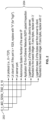
- FIG. 2 depicts an example document, comprising flow words corresponding to a given network endpoint, in accordance with some embodiments of the disclosure.
- the aforementioned flow words are each separated by a space, or underscore, in document 202.
- Each flow word has known meanings mapped in storage at server 100 (e.g., at storage circuitry 160).
- Exemplary meanings 204 are described in reference to each flow word of document 202, and are self-explanatory.
- the flow words fields shown in FIG. 2 are merely illustrative; any set of applicable fields may be used.
- control circuitry 102 feeds the document into a doc2vec algorithm.
- Doc2vec algorithms are described in detail in a publication entitled “ Distributed Representations of Sentences and Documents", authored by Le and Mikolov, and published in 2014 .
- Doc2vec is based on the word2vec algorithm, which is described in a publication entitled “ Efficient Estimation of Word Representations in Vector Space,” authored by Mikolov, Chen, Corrado, and Dean, and published in 2013 .
- Word2vec is further described in U.S. Pat. No. 9,037,464, issued on May 19, 2015 .
- control circuitry 102 uses a shallow neural network to generate a vector encoding for each word that appears in a given document, and for the document itself.
- control circuitry 102 implements a "Paragraph Vector - Distributed Bag of Words" formulation of the doc2vec algorithm. This entails control circuitry 102 implementing a sliding window (e.g., of a configurable or default size) iterating over the document by selecting a subset of words of the document.
- Control circuity 102 then applies a stochastic gradient descent to compute weights and biases that best fit the shallow neural network in predicting a target identifier for the endpoint. Control circuitry 102 then averages the set of weights for each word to compose a vector that represents the network endpoint to which the document corresponds.
- the endpoint vector may be represented as an array of floating point values. In some embodiments, the vector is formed of three-hundred to five-hundred floating point values.
- Control circuitry 102 causes each vector to be stored to memory, by storage circuitry 160.
- the vectors are limited in size, behavior modeling is possible without use of a "big data" facility.
- these records often include sensitive private information about users (e.g., personally-identifying information, financial information, and the like). Thus, if these records are inappropriately accessed (e.g., through a hacking or malware operation), legal and privacy issues may arise.
- Storage circuitry 160 may be any media capable of storing data.
- the computer readable media may be transitory, including, but not limited to, propagating electrical or electromagnetic signals, or may be non-transitory including, but not limited to, volatile and non-volatile computer memory or storage devices such as a hard disk, floppy disk, USB drive, DVD, CD, media cards, register memory, processor caches, Random Access Memory (“RAM”), etc.
- volatile and non-volatile computer memory or storage devices such as a hard disk, floppy disk, USB drive, DVD, CD, media cards, register memory, processor caches, Random Access Memory (“RAM”), etc.
- RAM Random Access Memory
- Control circuitry 102 may be based on any suitable processing circuitry, such as one or more microprocessors, microcontrollers, digital signal processors, programmable logic devices, field-programmable gate arrays (FPGAs), application-specific integrated circuits (ASICs), etc., and may include a multi-core processor (e.g., dual-core, quad-core, hexa-core, or any suitable number of cores) or supercomputer.
- processing circuitry may be distributed across multiple separate processors or processing units, for example, multiple of the same type of processing units (e.g., two Intel Core i7 processors) or multiple different processors (e.g., an Intel Core i5 processor and an Intel Core i7 processor).
- control circuitry 102 executes instructions stored in memory (i.e., storage circuitry 160).
- control circuitry 102 may receive a request from a network administrator to view a given endpoint vector. Control circuitry 102 may respond to such a request by using Application Program Interface ("API") 170 to output a visual depiction of a behavior model.
- API Application Program Interface
- control circuitry 102 may track behavior of the network endpoint over time. For example, by performing a word/document embedding computation (e.g., Doc2Vec or FastText) for a given network endpoint periodically over time, control circuitry 102 may identify recurring patterns of the endpoint. Differences in network behavior would be indicated by a movement of a resulting vector from subsequent computations to a different position in multidimensional space. Control circuitry 102 may implement Kalman filters to track the point position over time, or derive a multivariate Gaussian distribution to determine the probability of the point corresponding to the network endpoint's behavior being in a given position of the multidimensional space, or use a recursive neural network to learn behavior change over time. Control circuitry 102 may determine, if the point is located in a region of low probability value, that the network endpoint is engaged in anomalous behavior, and may alert a network administrator of the anomaly.
- a word/document embedding computation e.g., Doc2Vec or FastText
- FIG. 3 depicts an illustrative two-dimensional projection of a higher-dimensionality vector space, in accordance with some embodiments of the disclosure.
- the concentric ovals depicted in vector space 300 each correspond to a different probability value of where a network administrator would expect a given network endpoint to be.
- Point 302, marked with the character "A” illustrates a location that control circuitry 102 would deem to be a normal behavior for the endpoint. If, however, control circuitry 102 determines that the location described by the endpoint vector moves to point 306, marked with "A'", control circuitry 102 may alert a network administrator of anomalous behavior. Control circuitry 102 may determine to issue the alert based on point 306 being outside of the boundaries of normalcy threshold 304, which may be configured by a network administrator, or may be a default value.
- FIG. 4 is an illustrative depiction of a projection on 3D space of multiple endpoint vectors, in accordance with some embodiments of the disclosure.
- a network administrator may request to view a typical behavior of endpoints in large and heterogeneous networks, in order to identify clusters of endpoints with similar behavior and to quantify their population.
- Control circuitry 102 may use API 170 to output a visualization of such a 3D space, e.g., by depicting cluster 402, cluster 404, cluster 406, and cluster 408. Each of these clusters are depicted closely to one another due to their having similar network behaviors.
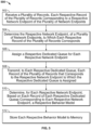
- FIG. 5 depicts an illustrative flowchart of a process for reducing storage space used in tracking behavior of a plurality of network endpoints by modeling the behavior with a behavior model, in accordance with some embodiments of the disclosure.
- Process 500 begins at 502, where control circuitry (e.g., control circuitry 102 of server 100) receives a plurality of records, each respective record of the plurality of records corresponding to a respective network endpoint of the plurality of network endpoints.
- control circuitry e.g., control circuitry 102 of server 100
- Process 500 continues to 504, where control circuitry 102 determines the respective network endpoint, of a plurality of network endpoints (e.g., network endpoint 112 and network endpoint 114 of network 110), to which each respective record of the plurality of records corresponds.
- control circuitry 102 assigns a respective dedicated queue for each respective network endpoint (e.g., queue 142 and queue 144 of queues 140).
- control circuitry 102 transmits, to each respective dedicated queue, each record of the plurality of records that corresponds to the respective network endpoint to which the respective dedicated queue is assigned.
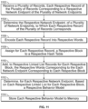
- control circuitry 102 determines, for each respective network endpoint, based on each record of each respective dedicated queue corresponding to each respective network endpoint, a respective behavior model. Control circuitry 102 may perform this determination using any of modules 150.
- control circuitry 102 stores each respective behavior model to memory (e.g., using storage circuitry 160).
- FIG. 6 depicts an illustrative flowchart for a process for determining a respective behavior module, in accordance with some embodiments of the disclosure.
- Process 600 begins at 602, where control circuitry 102 initiates a subroutine for determining the respective behavior model (e.g., a subroutine for effecting 510 of FIG. 5 ).
- control circuitry 102 identifies a plurality of modules programmed to determine behavior models (e.g., modules 150).
- control circuitry 102 identifies a module of the plurality of modules that is idle, and at 608, control circuitry 102 commands the idle module to determine the respective behavior model.
- FIG. 7 depicts an illustrative flowchart for a process for alerting a network administrator of anomalous network endpoint behavior, in accordance with some embodiments of the disclosure.
- Process 700 begins at 702, where control circuitry 102 determines whether a given floating point value represents abnormal behavior for a given respective network endpoint (e.g., network endpoint 112). If the determination is in the negative, control circuitry 102 determines that the network endpoint is behaving normally. If the determination is in the affirmative, process 700 proceeds to 704, where control circuitry 102 alerts a network administrator (e.g., using API 170), performs a set of predefined actions, or similar.
- a network administrator e.g., using API 170
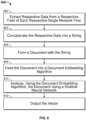
- FIG. 8 depicts an illustrative flowchart of a process for generating a vector that models endpoint device behavior using a word/document embedding algorithm (e.g., doc2vec), in accordance with some embodiments of the disclosure.
- Process 800 begins at 802, where control circuitry 102 extracts respective data from a respective field of each respective single network flow. At 804, control circuitry 102 concatenates the respective data into a string. At 806, control circuitry 102 forms a document with the string (e.g., document 202). At 808, control circuitry 102 feeds the document into a word/document embedding algorithm (e.g., doc2vec or FastText).
- a word/document embedding algorithm e.g., doc2vec or FastText
- control circuitry 102 analyzes, using the word/document embedding algorithm, the document using a shallow neural network.
- control circuitry 102 outputs the vector (e.g., to storage 160, or to API 170 for a visual representation to be generated).
- FIG. 9 depicts an illustrative flowchart of a process for generating for display a visual representation of a behavior model, in accordance with some embodiments of the disclosure.
- Process 900 begins at 902, where control circuitry 102 determines whether a command is received to view a respective behavior model for a given network endpoint. If the determination is in the negative, process 900 ends. If the determination is in the affirmative, process 900 continues to 904, where control circuitry 102 generates for display a graphical representation of the respective behavior model for the given network endpoint (e.g., the representation depicted in FIG. 3 ).
- control circuitry 102 determines a different network endpoint that has a respective behavior model showing similar behavior to behavior of the given network endpoint.
- control circuitry 102 generates for simultaneous display with the graphical representation of the respective behavior model for the given network endpoint, the respective behavior model for the different network endpoint (e.g., the representation depicted in FIG. 4 ).
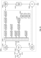
- FIG. 10 depicts a system for reducing storage space used in tracking behavior of a plurality of network endpoints by modeling the behavior with a behavior model using a hash table, in accordance with some embodiments of the disclosure.
- FIG. 10 includes server 1000, which acts in the manner in which server 100 acts, as described above.
- Server 1000 receives records from network endpoints of network 1014 (e.g., network endpoint 1012 and network endpoint 1014).
- Network 1014 acts in the manner in which network 110 acts, as described above.
- Network endpoint 1012 and network endpoint 1014 act in the manner in which network endpoint 112 and network endpoint 1014 act, as described above.
- Server 1000 receives the records using communications circuitry 1020, which acts in the manner communications circuitry 120 acts, as described above.
- Ingest module 1030 receives the records from network 1010, and operates in accordance with the manners described above. For example, the operations of control circuitry 102 in connection with buffer 130 described above are equivalent to the manner in which control circuitry 1002 interacts with ingest module 1030. Records ingested by ingest module 1030 are forwarded to word encoding module 1040. Word encoding module 1040 encodes records to words in accordance with the manners described in the foregoing. For example, word encoding will result in flow words being generated, such as the flow words depicted in FIG. 2 .
- control circuitry 1002 may feed hash table 1050 into language model 1060.
- control circuitry 1002 determines that hash table 1050 is populated based on the passage of a threshold amount of time, which may be configured by a network administrator, or may be a default amount of time.
- control circuitry 1002 determines that hash table 1050 is populated based on population of a threshold number of words (e.g., one million words). This can be words in the aggregate for all end points, or words in the aggregate for a single endpoint.
- Language model 1060 generates a behavior model for each endpoint based on the words populated for each endpoint.
- the behavior model is generated based on an algorithm derived upon "FastText", which is described in a publication entitled “ Enriching Word Vectors with Subword Information", authored by P. Bojanowski, E. Grave, A. Joulin, and T. Mikolov, and published in 2016 .
- FastText is itself based on the word2vec algorithm discussed above.
- Control circuitry 1002 commands the behavior models generated using language model 1060 to be stored at model store 1070, which acts in accordance with the manner in which storage circuitry 160 acts, as described above.
- Control circuitry 1002 may cause behavior models to be output to a user using API 1080, in any manner described above with respect to API 170.
- FIG. 11 depicts an illustrative flowchart of a process for reducing storage space used in tracking behavior of a plurality of network endpoints by modeling the behavior with a behavior model using a hash table, in accordance with some embodiments of the disclosure.
- Process 1100 begins at 1102, where control circuitry (e.g., control circuitry 1002) receives a plurality of records (e.g., from network endpoint 1012 of network 1014), each respective record of the plurality of records corresponding to a respective network endpoint of the plurality of network endpoints.
- Process 1000 continues to 1104, where control circuitry 1002 determines the respective network endpoint, of a plurality of network endpoints, to which each respective record of the plurality of records corresponds.
- control circuitry 1002 encodes each respective record into respective words.
- control circuitry 1002 assigns for each respective record, a respective block to a respective hash table (e.g., hash table 1050).
- control circuitry 1002 adds, to respective linked list records for each respective block (e.g., using linked list 1054), the respective words corresponding to the network endpoint corresponding to each respective block.
- control circuitry 1002 determines, for each respective network endpoint, based on each respective linked list for each respective block, a respective behavior model (e.g., using language model 1060).
- control circuitry 1002 stores each respective behavior model to memory (e.g., using model store 1070).
- the foregoing describes systems, methods, and apparatuses for generating and storing zero-footprint behavior models of network endpoints (e.g., from network 110).
- the above-described embodiments of the present disclosure are presented for the purposes of illustration and not of limitation.
- the present disclosure is not limited to a particular implementation.
- one or more steps of the methods described above may be performed in a different order (or concurrently) and still achieve desirable results.
- the disclosure may be implemented in hardware, such as on an application-specific integrated circuit (ASIC) or on a field-programmable gate array (FPGA).
- ASIC application-specific integrated circuit
- FPGA field-programmable gate array
- the disclosure may also be implemented in software by, for example, encoding transitory or non-transitory instructions for performing the process discussed above in one or more transitory or non-transitory computer-readable media.
Landscapes
- Engineering & Computer Science (AREA)
- Theoretical Computer Science (AREA)
- Signal Processing (AREA)
- Computer Networks & Wireless Communication (AREA)
- Physics & Mathematics (AREA)
- General Engineering & Computer Science (AREA)
- Health & Medical Sciences (AREA)
- Artificial Intelligence (AREA)
- Computational Linguistics (AREA)
- General Health & Medical Sciences (AREA)
- General Physics & Mathematics (AREA)
- Data Mining & Analysis (AREA)
- Biophysics (AREA)
- Computing Systems (AREA)
- Molecular Biology (AREA)
- Mathematical Physics (AREA)
- Software Systems (AREA)
- Evolutionary Computation (AREA)
- Biomedical Technology (AREA)
- Life Sciences & Earth Sciences (AREA)
- Audiology, Speech & Language Pathology (AREA)
- Data Exchanges In Wide-Area Networks (AREA)
- Computer And Data Communications (AREA)
- Human Computer Interaction (AREA)
Description
- Traditionally, using a central server to monitor network behavior of many network end point devices requires storing myriad records of network flows for analysis. For example, existing systems require storage of Net flow and Internet Protocol Flow Information Export ("IPFIX") records, Hypertext Transfer Protocol ("HTTP") proxy logs, and the like, in a "big data" backend for subsequent processing. This involves great expense, as storing these records requires use of large amounts of storage space, amounting to many terabytes, and real estate to house the storage space (i.e., the "big data" facilities) is similarly expensive. This problem is exacerbated by the proliferation of gadgets and other devices becoming network-connected (e.g., Internet-of-Things devices), which multiplies the amount of network endpoints to be monitored, making it impractical to store network flows for all network devices for the purpose of behavior monitoring.
-
US 2016/261465 A1 relates to behavioural analysis to automate monitoring Internet of Things (IoT) device health in a direct and/or indirect manner. - Systems and methods are disclosed herein for monitoring behavior of network endpoints without a need for a "big data" storage backend. Specifically, the systems and methods disclosed herein reduce the records of network flows to vectors, thus enabling the system to save behavior models of millions of network endpoints, or more, using only a small amount of storage (e.g., a few gigabytes of storage).
- Aspects of the present invention are set out in the accompanying claims.
- In some aspects of the disclosure, control circuitry receives a plurality of records, each respective record of the plurality of records corresponding to a respective network endpoint of the plurality of network endpoints. Each respective record may identify a respective single network flow originating from the respective network endpoint that corresponds to the respective record. The control circuitry may determine a respective network endpoint, of a plurality of network endpoints, to which each respective record of the plurality of records corresponds.
- The control circuitry may assign a respective dedicated queue for each respective network endpoint. For example, the control circuitry may dedicate a single first-in-first-out ("FIFO") queue for all records originating from a given network endpoint. The control circuitry may then transmit, to each respective dedicated queue, each record of the plurality of records that corresponds to the respective network endpoint to which the respective dedicated queue is assigned.
- The control circuitry may determine, for each respective network endpoint, based on each record of each respective dedicated queue corresponding to each respective network endpoint, a respective behavior model, and may store each respective behavior model to memory. In some embodiments, the control circuitry, when determining the respective behavior model, may identify a plurality of modules programmed to determine behavior models, and may identify a module of the plurality of modules that is idle. The control circuitry may command the idle module to determine the respective behavior model. The module may be a software instantiation of an algorithm for determining a behavior model based on the records of a given queue.
- In some embodiments, the control circuitry, when determining the respective behavior model, encodes data of the set of respective records as a multi-dimensional vector of floating point values. The control circuitry may determine whether a given multi-dimensional vector represents abnormal behavior for a given respective network endpoint. In response to determining that the given multi-dimensional vector represents abnormal behavior for the given respective network endpoint, the control circuitry may alert a network administrator or perform a set of predefined actions.
- The control circuitry, when encoding the data of each respective record within the respective dedicated queues, may extract respective data from a respective field of each respective single network flow, concatenate the respective data into a string, and convert the string into a vector. Each respective data point may form a point in the vector. The control circuitry may use the vector as the respective behavior model.
- The control circuitry, when converting the string into the vector, may form a document with the string. The control circuitry may then feed the document into a word/document embedding algorithm (e.g., Document to Vector ("doc2vec"), FastText, and the like), and, using the doc2vec algorithm, may analyze the document using a shallow neural network. The control circuitry may then output, based on the analyzing, the vector.
- In some embodiments, the plurality of records is of a first data size, where a sum of a data size of each respective behavior model is of a second data size, and where the second data size is two or more orders of magnitude smaller than the first data size. For example, while the plurality of records may amount to hundreds of terabytes of data, the vectors, taken together, that represent the records, may amount to a few gigabytes of data.
- In some embodiments, the control circuitry may receive a command from a network administrator to view a respective behavior model for a given network endpoint. In response to receiving the command, the control circuitry may generate for display a graphical representation of the respective behavior model for the given network endpoint. Furthermore, the control circuitry may determine a different network endpoint that has a respective behavior model showing similar behavior to behavior of the given network endpoint, and may generate for simultaneous display with the graphical representation of the respective behavior model for the given network endpoint, the respective behavior model for the different network endpoint.
- In some aspects, systems and methods are enclosed for reducing storage space used in tracking behavior of a plurality of network endpoints by using a hash table and modeling the behavior with a behavior model. Control circuitry may receive a plurality of records, each respective record of the plurality of records corresponding to a respective network endpoint of the plurality of network endpoints. Control circuitry may determine the respective network endpoint, of a plurality of network endpoints, to which each respective record of the plurality of records corresponds, and may encode each respective record into respective words.
- In some embodiments, the control circuitry assigns, for each respective record, a respective block to a respective hash table, and adds, to respective linked list records for each respective block, the respective words corresponding to each network endpoint corresponding to each respective block. The control circuitry determines, for each respective network endpoint, based on each respective linked list for each respective block, a respective behavior model, and stores each respective behavior model to memory.
- The control circuitry, when assigning, for each respective record, a respective block to a respective hash table, may monitor the plurality of records for a record corresponding to an unknown network endpoint. In response to detecting, from the monitoring, an unknown network endpoint, the control circuitry may add a block corresponding to the unknown network endpoint to the hash table.
- In some embodiments, the control circuitry may determine, for each respective network endpoint, based on each respective linked list for each respective block, a respective behavior model in response to detecting a threshold amount of words have accumulated for a given respective network endpoint. In some embodiments, the control circuitry, when determining for each respective network endpoint, based on each respective linked list for each respective block, a respective behavior model, may feed the hash table through a word/document embedding algorithm (such as the FastText algorithm).
- The above and other objects and advantages of the disclosure will be apparent upon consideration of the following detailed description, taken in conjunction with the accompanying drawings, in which like reference characters refer to like parts throughout, and in which:
-
FIG. 1 depicts a system for reducing storage space used in tracking behavior of a plurality of network endpoints by modeling the behavior with a behavior model; -
FIG. 2 depicts an example document, comprising flow words corresponding to a given network endpoint; -
FIG. 3 depicts an illustrative two-dimensional projection of a higher-dimensionality vector space; -
FIG. 4 is an illustrative depiction of a projection on 3D space of multiple endpoint vectors; -
FIG. 5 depicts an illustrative flowchart of a process for reducing storage space used in tracking behavior of a plurality of network endpoints by modeling the behavior with a behavior model; -
FIG. 6 depicts an illustrative flowchart for a process for determining a respective behavior module; -
FIG. 7 depicts an illustrative flowchart for a process for alerting a network administrator of anomalous network endpoint behavior; -
FIG. 8 depicts an illustrative flowchart of a process for generating a vector that models endpoint device behavior using a word/document embedding algorithm; -
FIG. 9 depicts an illustrative flowchart of a process for generating for display a visual representation of a behavior model; -
FIG. 10 depicts a system for reducing storage space used in tracking behavior of a plurality of network endpoints by modeling the behavior with a behavior model using a hash table; and -
FIG. 11 depicts an illustrative flowchart of a process for reducing storage space used in tracking behavior of a plurality of network endpoints by modeling the behavior with a behavior model using a hash table. -
FIG. 1 depicts a system for reducing storage space used in tracking behavior of a plurality of network endpoints by modeling the behavior with a behavior model, in accordance with some embodiments of the disclosure. As depicted inFIG. 1 ,server 100 is used to model behavior of network endpoints ofnetwork 110, such asnetwork endpoint 112 andnetwork endpoint 114. Whileserver 100 is depicted as one server including several components, this is merely for convenience; the components ofserver 100 may be distributed across multiple servers and databases. As used herein, a network endpoint may be any end device, such as a consumer electronics device (e.g., smartphone, personal computer, etc.), an Internet-of-Things device, or any other user-facing device that is connected tonetwork 110. -
Control circuitry 102 ofserver 100 receives records from network endpoints of network 110 (e.g.,network device 112 and network device 114) by way ofcommunications circuitry 120.Communications circuitry 120 may be any known receiver, transmitter, transceiver, or any other known means of transmitting and/or receiving data. As used herein, the term "record" may refer to logs of network activities. Examples of records are Netflow records, IPFIX records, HTTP proxy logs, and the like. In some embodiments, each record identifies a single network flow. In some embodiments,control circuitry 102 may augment the records to include extra metadata, such as an application identifier, HTTP/HTTPs (HTTP Secure) header values, Transport Layer Security ("TLS") certificate details, and the like.Control circuitry 102 may augment the records through a fingerprinting process, and/or can perform this augmentation by ingesting bidirectional IPFIX records. - The records may be received at
buffer 130.Control circuitry 102 may determine to which network endpoint each record corresponds. For example,control circuitry 102 may differentiate records that correspond to networkendpoint 112 from records that correspond to networkendpoint 114.Control circuitry 102 may then designate a different queue for each network endpoint, such that records corresponding to each different network endpoint are transmitted frombuffer 130 to a designated queue ofqueues 140. As depicted inFIG. 1 , records corresponding to networkendpoint 112 may be transmitted to queue 142, and records corresponding to networkendpoint 114 may be transmitted toqueue 144.Control circuitry 102 may instantiate as many queues n as is necessary to use a dedicated queue for each network endpoint for which records are received. In some embodiments,queues 140 are FIFO queues. In other embodiments,queues 140 may be any form of queue. - In some embodiments,
control circuitry 102 schedules processing of the records inqueues 140, where processing is performed bymodules 150.Modules 150 are not dedicated to a given queue. As an example,queue 144 may be assigned tomodule 152 for processing, as depicted inFIG. 1 . When any ofmodules 154 completes processing of the records from a given queue, themodules 154 revert to an idle state. - In some embodiments,
control circuitry 102 identifies idle modules, and commands each idle module to process records from a specific queue. In selecting to which queue ofqueues 150 an idle module should be assigned, control circuitry may determine which queues are overflowing in size by determining which queues have a number of records that exceed a threshold. In some embodiments, the threshold is configured by a network administrator. In some embodiments, the threshold is a default value.Control circuitry 102 may prioritize queues that have a number of records that exceed the threshold by assigning idle modules to those queues first. Control circuitry may assign remaining idle modules based on any known load balancing scheme (e.g., based on which queues have the most records), or arbitrarily. -
Modules 150 generate a behavior model as a result of processing the records of a given queue ofqueues 140. A given module (e.g., module 154) generates the behavior model by encoding data of the records into a multi-dimensional vector. In order to encode the data,control circuitry 102 instructs a module of module 150 (e.g., module 152) to extract data from a subset of fields of records of a given queue (e.g., queue 144).Control circuitry 102 instructs the module (e.g., module 152) to generate a string from the extracted data (the string is also referred to as a "flow word" herein).Control circuitry 202 then concatenates the "flow words" derived from the queue to form a document. -
FIG. 2 depicts an example document, comprising flow words corresponding to a given network endpoint, in accordance with some embodiments of the disclosure. The aforementioned flow words are each separated by a space, or underscore, indocument 202. Each flow word has known meanings mapped in storage at server 100 (e.g., at storage circuitry 160).Exemplary meanings 204 are described in reference to each flow word ofdocument 202, and are self-explanatory. The flow words fields shown inFIG. 2 are merely illustrative; any set of applicable fields may be used. - After forming a document,
control circuitry 102 feeds the document into a doc2vec algorithm. Doc2vec algorithms are described in detail in a publication entitled "Distributed Representations of Sentences and Documents", authored by Le and Mikolov, and published in 2014. Doc2vec is based on the word2vec algorithm, which is described in a publication entitled "Efficient Estimation of Word Representations in Vector Space," authored by Mikolov, Chen, Corrado, and Dean, and published in 2013. Word2vec is further described inU.S. Pat. No. 9,037,464, issued on May 19, 2015 - In brief, when
control circuitry 102 feeds the document into the doc2vec algorithm,control circuitry 102 uses a shallow neural network to generate a vector encoding for each word that appears in a given document, and for the document itself. As described in the aforementioned publications that describe doc2vec and word2vec algorithms, in one embodiment of the disclosure,control circuitry 102 implements a "Paragraph Vector - Distributed Bag of Words" formulation of the doc2vec algorithm. This entailscontrol circuitry 102 implementing a sliding window (e.g., of a configurable or default size) iterating over the document by selecting a subset of words of the document.Control circuity 102 then applies a stochastic gradient descent to compute weights and biases that best fit the shallow neural network in predicting a target identifier for the endpoint.Control circuitry 102 then averages the set of weights for each word to compose a vector that represents the network endpoint to which the document corresponds. The endpoint vector may be represented as an array of floating point values. In some embodiments, the vector is formed of three-hundred to five-hundred floating point values. -
Control circuitry 102 causes each vector to be stored to memory, bystorage circuitry 160. Moreover, as described above, because the vectors are limited in size, behavior modeling is possible without use of a "big data" facility. There are additional advantages to avoiding storing the records themselves. Namely, these records often include sensitive private information about users (e.g., personally-identifying information, financial information, and the like). Thus, if these records are inappropriately accessed (e.g., through a hacking or malware operation), legal and privacy issues may arise. The storage of a vector, as disclosed herein, rather than storing the records themselves, avoids these risks by avoiding storing such sensitive information, while still maintaining the ability to monitor the behavior of the network endpoint. -
Storage circuitry 160 may be any media capable of storing data. The computer readable media may be transitory, including, but not limited to, propagating electrical or electromagnetic signals, or may be non-transitory including, but not limited to, volatile and non-volatile computer memory or storage devices such as a hard disk, floppy disk, USB drive, DVD, CD, media cards, register memory, processor caches, Random Access Memory ("RAM"), etc.Control circuitry 102 may be based on any suitable processing circuitry, such as one or more microprocessors, microcontrollers, digital signal processors, programmable logic devices, field-programmable gate arrays (FPGAs), application-specific integrated circuits (ASICs), etc., and may include a multi-core processor (e.g., dual-core, quad-core, hexa-core, or any suitable number of cores) or supercomputer. In some embodiments, processing circuitry may be distributed across multiple separate processors or processing units, for example, multiple of the same type of processing units (e.g., two Intel Core i7 processors) or multiple different processors (e.g., an Intel Core i5 processor and an Intel Core i7 processor). In some embodiments,control circuitry 102 executes instructions stored in memory (i.e., storage circuitry 160). - Following storage of an endpoint vector,
control circuitry 102 may receive a request from a network administrator to view a given endpoint vector.Control circuitry 102 may respond to such a request by using Application Program Interface ("API") 170 to output a visual depiction of a behavior model. - In some embodiments,
control circuitry 102 may track behavior of the network endpoint over time. For example, by performing a word/document embedding computation (e.g., Doc2Vec or FastText) for a given network endpoint periodically over time,control circuitry 102 may identify recurring patterns of the endpoint. Differences in network behavior would be indicated by a movement of a resulting vector from subsequent computations to a different position in multidimensional space.Control circuitry 102 may implement Kalman filters to track the point position over time, or derive a multivariate Gaussian distribution to determine the probability of the point corresponding to the network endpoint's behavior being in a given position of the multidimensional space, or use a recursive neural network to learn behavior change over time.Control circuitry 102 may determine, if the point is located in a region of low probability value, that the network endpoint is engaged in anomalous behavior, and may alert a network administrator of the anomaly. -
FIG. 3 depicts an illustrative two-dimensional projection of a higher-dimensionality vector space, in accordance with some embodiments of the disclosure. The concentric ovals depicted invector space 300 each correspond to a different probability value of where a network administrator would expect a given network endpoint to be.Point 302, marked with the character "A", illustrates a location that controlcircuitry 102 would deem to be a normal behavior for the endpoint. If, however,control circuitry 102 determines that the location described by the endpoint vector moves to point 306, marked with "A'",control circuitry 102 may alert a network administrator of anomalous behavior.Control circuitry 102 may determine to issue the alert based onpoint 306 being outside of the boundaries ofnormalcy threshold 304, which may be configured by a network administrator, or may be a default value. -
FIG. 4 is an illustrative depiction of a projection on 3D space of multiple endpoint vectors, in accordance with some embodiments of the disclosure. In some embodiments, a network administrator may request to view a typical behavior of endpoints in large and heterogeneous networks, in order to identify clusters of endpoints with similar behavior and to quantify their population.Control circuitry 102, receiving such a request, may useAPI 170 to output a visualization of such a 3D space, e.g., by depictingcluster 402,cluster 404,cluster 406, andcluster 408. Each of these clusters are depicted closely to one another due to their having similar network behaviors. -
FIG. 5 depicts an illustrative flowchart of a process for reducing storage space used in tracking behavior of a plurality of network endpoints by modeling the behavior with a behavior model, in accordance with some embodiments of the disclosure.Process 500 begins at 502, where control circuitry (e.g.,control circuitry 102 of server 100) receives a plurality of records, each respective record of the plurality of records corresponding to a respective network endpoint of the plurality of network endpoints. -
Process 500 continues to 504, wherecontrol circuitry 102 determines the respective network endpoint, of a plurality of network endpoints (e.g.,network endpoint 112 andnetwork endpoint 114 of network 110), to which each respective record of the plurality of records corresponds. At 506,control circuitry 102 assigns a respective dedicated queue for each respective network endpoint (e.g.,queue 142 and queue 144 of queues 140). - At 508,
control circuitry 102 transmits, to each respective dedicated queue, each record of the plurality of records that corresponds to the respective network endpoint to which the respective dedicated queue is assigned. At 510,control circuitry 102 determines, for each respective network endpoint, based on each record of each respective dedicated queue corresponding to each respective network endpoint, a respective behavior model.Control circuitry 102 may perform this determination using any ofmodules 150. At 512,control circuitry 102 stores each respective behavior model to memory (e.g., using storage circuitry 160). -
FIG. 6 depicts an illustrative flowchart for a process for determining a respective behavior module, in accordance with some embodiments of the disclosure.Process 600 begins at 602, wherecontrol circuitry 102 initiates a subroutine for determining the respective behavior model (e.g., a subroutine for effecting 510 ofFIG. 5 ). At 604,control circuitry 102 identifies a plurality of modules programmed to determine behavior models (e.g., modules 150). At 606,control circuitry 102 identifies a module of the plurality of modules that is idle, and at 608,control circuitry 102 commands the idle module to determine the respective behavior model. -
FIG. 7 depicts an illustrative flowchart for a process for alerting a network administrator of anomalous network endpoint behavior, in accordance with some embodiments of the disclosure.Process 700 begins at 702, wherecontrol circuitry 102 determines whether a given floating point value represents abnormal behavior for a given respective network endpoint (e.g., network endpoint 112). If the determination is in the negative,control circuitry 102 determines that the network endpoint is behaving normally. If the determination is in the affirmative,process 700 proceeds to 704, wherecontrol circuitry 102 alerts a network administrator (e.g., using API 170), performs a set of predefined actions, or similar. -
FIG. 8 depicts an illustrative flowchart of a process for generating a vector that models endpoint device behavior using a word/document embedding algorithm (e.g., doc2vec), in accordance with some embodiments of the disclosure.Process 800 begins at 802, wherecontrol circuitry 102 extracts respective data from a respective field of each respective single network flow. At 804,control circuitry 102 concatenates the respective data into a string. At 806,control circuitry 102 forms a document with the string (e.g., document 202). At 808,control circuitry 102 feeds the document into a word/document embedding algorithm (e.g., doc2vec or FastText). At 810,control circuitry 102 analyzes, using the word/document embedding algorithm, the document using a shallow neural network. At 812,control circuitry 102 outputs the vector (e.g., tostorage 160, or toAPI 170 for a visual representation to be generated). -
FIG. 9 depicts an illustrative flowchart of a process for generating for display a visual representation of a behavior model, in accordance with some embodiments of the disclosure.Process 900 begins at 902, wherecontrol circuitry 102 determines whether a command is received to view a respective behavior model for a given network endpoint. If the determination is in the negative,process 900 ends. If the determination is in the affirmative,process 900 continues to 904, wherecontrol circuitry 102 generates for display a graphical representation of the respective behavior model for the given network endpoint (e.g., the representation depicted inFIG. 3 ). At 906,control circuitry 102 determines a different network endpoint that has a respective behavior model showing similar behavior to behavior of the given network endpoint. At 908,control circuitry 102 generates for simultaneous display with the graphical representation of the respective behavior model for the given network endpoint, the respective behavior model for the different network endpoint (e.g., the representation depicted inFIG. 4 ). -
FIG. 10 depicts a system for reducing storage space used in tracking behavior of a plurality of network endpoints by modeling the behavior with a behavior model using a hash table, in accordance with some embodiments of the disclosure.FIG. 10 includesserver 1000, which acts in the manner in whichserver 100 acts, as described above.Server 1000 receives records from network endpoints of network 1014 (e.g.,network endpoint 1012 and network endpoint 1014).Network 1014 acts in the manner in which network 110 acts, as described above.Network endpoint 1012 andnetwork endpoint 1014 act in the manner in whichnetwork endpoint 112 andnetwork endpoint 1014 act, as described above.Server 1000 receives the records usingcommunications circuitry 1020, which acts in themanner communications circuitry 120 acts, as described above. - Ingest
module 1030 receives the records fromnetwork 1010, and operates in accordance with the manners described above. For example, the operations ofcontrol circuitry 102 in connection withbuffer 130 described above are equivalent to the manner in whichcontrol circuitry 1002 interacts with ingestmodule 1030. Records ingested by ingestmodule 1030 are forwarded toword encoding module 1040.Word encoding module 1040 encodes records to words in accordance with the manners described in the foregoing. For example, word encoding will result in flow words being generated, such as the flow words depicted inFIG. 2 . - After encoding the records from the network endpoints to words,
control circuitry 1002 modifies hash table 1050 to include records corresponding to each network endpoint. For example,control circuitry 1002 may determine whether a network endpoint (e.g., endpoint10 corresponding toendpoint 1014 in network 1010) already has an entry on the hash table. Ifcontrol circuitry 1002 determines that there is no entry for endpoint10 on hash table 1050,control circuitry 1002 adds a block to hash table 1050 for endpoint10, such asblock 1052.Control circuitry 1002 associates, for each network endpoint, words encoded byword encoding module 1040 into a linked list (e.g., linked list 1054) corresponding to a given network endpoint. - After hash table 1050 is populated,
control circuitry 1002 may feed hash table 1050 intolanguage model 1060. In some embodiments,control circuitry 1002 determines that hash table 1050 is populated based on the passage of a threshold amount of time, which may be configured by a network administrator, or may be a default amount of time. In some embodiments,control circuitry 1002 determines that hash table 1050 is populated based on population of a threshold number of words (e.g., one million words). This can be words in the aggregate for all end points, or words in the aggregate for a single endpoint.Language model 1060 generates a behavior model for each endpoint based on the words populated for each endpoint. The behavior model is generated based on an algorithm derived upon "FastText", which is described in a publication entitled "Enriching Word Vectors with Subword Information", authored by P. Bojanowski, E. Grave, A. Joulin, and T. Mikolov, and published in 2016. FastText is itself based on the word2vec algorithm discussed above.Control circuitry 1002 commands the behavior models generated usinglanguage model 1060 to be stored atmodel store 1070, which acts in accordance with the manner in whichstorage circuitry 160 acts, as described above.Control circuitry 1002 may cause behavior models to be output to auser using API 1080, in any manner described above with respect toAPI 170. -
FIG. 11 depicts an illustrative flowchart of a process for reducing storage space used in tracking behavior of a plurality of network endpoints by modeling the behavior with a behavior model using a hash table, in accordance with some embodiments of the disclosure. Process 1100 begins at 1102, where control circuitry (e.g., control circuitry 1002) receives a plurality of records (e.g., fromnetwork endpoint 1012 of network 1014), each respective record of the plurality of records corresponding to a respective network endpoint of the plurality of network endpoints.Process 1000 continues to 1104, wherecontrol circuitry 1002 determines the respective network endpoint, of a plurality of network endpoints, to which each respective record of the plurality of records corresponds. - At 1106,
control circuitry 1002 encodes each respective record into respective words. At 1108,control circuitry 1002 assigns for each respective record, a respective block to a respective hash table (e.g., hash table 1050). At 1110,control circuitry 1002 adds, to respective linked list records for each respective block (e.g., using linked list 1054), the respective words corresponding to the network endpoint corresponding to each respective block. At 1112,control circuitry 1002 determines, for each respective network endpoint, based on each respective linked list for each respective block, a respective behavior model (e.g., using language model 1060). At 1114,control circuitry 1002 stores each respective behavior model to memory (e.g., using model store 1070). - For brevity, elements of processes 300-900 and 1100 that were described in detail with respect to
FIGS. 1 and2 are not repeated in the description ofFIGS. 3-9 andFIG. 11 , but those above-described elements are intended to carry into their respective descriptions ofFIGS. 3-9 andFIG. 11 . - The foregoing describes systems, methods, and apparatuses for generating and storing zero-footprint behavior models of network endpoints (e.g., from network 110). The above-described embodiments of the present disclosure are presented for the purposes of illustration and not of limitation. Furthermore, the present disclosure is not limited to a particular implementation. For example, one or more steps of the methods described above may be performed in a different order (or concurrently) and still achieve desirable results. In addition, the disclosure may be implemented in hardware, such as on an application-specific integrated circuit (ASIC) or on a field-programmable gate array (FPGA). The disclosure may also be implemented in software by, for example, encoding transitory or non-transitory instructions for performing the process discussed above in one or more transitory or non-transitory computer-readable media.
- As referred herein, the term "in response to" refers to initiated as a result of. For example, a first action being performed in response to a second action may include interstitial steps between the first action and the second action.
Claims (16)
- A method for reducing storage space used in tracking behavior of a plurality of network endpoints (112, 114) by modeling the behavior with a behavior model, the method comprising:receiving (502) a plurality of records, each respective record of the plurality of records corresponding to a respective network endpoint (112, 114) of the plurality of network endpoints;determining (504) the respective network endpoint, of the plurality of network endpoints, to which each respective record of the plurality of records corresponds;assigning (506) a respective dedicated queue (142, 144) for each respective network endpoint (112, 114);transmitting (508), to each respective dedicated queue (142, 144), each record of the plurality of records that corresponds to the respective network endpoint to which the respective dedicated queue is assigned;generating, for each respective network endpoint (112, 114), using records of the respective dedicated queue corresponding to the respective network endpoint, a respective vector representing a respective behavior model, wherein the generating the respective vector further comprises:encoding each respective record of the records within the respective dedicated queue as a respective string, wherein the encoding each respective record comprises extracting (802) data from a subset of fields of the respective record, and concatenating (804) the data into the respective string;forming (806) a document with each string encoded from the respective record of the records in the respective dedicated queue;feeding (808) the document into a Document to Vector (doc2vec) algorithm;analyzing (810), using the doc2vec algorithm, the document; andoutputting (812), based on the analyzing, the respective vector;storing (512) each respective vector to a memory (160); anddetermining (702) an anomalous behavior state for a network endpoint (112, 114) in the plurality of network endpoints by comparing the respective vector of the network endpoint to a normalcy threshold (304) in a multidimensional space.
- The method of claim 1, wherein generating the respective vector representing the respective behavior model further comprises:identifying (604) a plurality of modules (150; 152, 154) programmed to generate the respective vectors representing the respective behavior models;identifying (606) a module (152, 154) of the plurality of modules that is idle; andcommanding (608) the idle module to generate the respective vector representing the respective behavior model.
- The method of claim 1, further comprising:
tracking behavior of each respective network endpoint over time by comparing a current position (306) of the respective vector in the multidimensional space to a previous position (302) of a previous version of the respective vector in the multidimensional space. - The method of claim 3, wherein the tracking is performed using a Kalman filter.
- The method of claim 1, wherein each respective record identifies a respective single network flow originating from the respective network endpoint that corresponds to the respective record.
- The method of claim 1, wherein the generating the respective vectors representing the respective behavior models further comprises:identifying (604) a plurality of modules (150; 152, 154) programmed to generate the respective vectors representing the respective behavior models;identifying (606) modules (152, 154) of the plurality of modules that are idle;determining first dedicated queues each having a number of records that exceed a threshold value; andassigning a first portion of the identified idle modules to the first dedicated queues.
- The method of claim 6, wherein the generating the respective vectors representing the respective behavior models further comprises:
assigning a second portion of the identified idle modules to second dedicated queues based on a load balancing scheme. - The method of claim 1, wherein the plurality of records is of a first data size, wherein a sum of a data size of each respective behavior model is of a second data size, and wherein the second data size is two or more orders of magnitude smaller than the first data size.
- The method of claim 1, wherein the analyzing, using the doc2vec algorithm, the document comprises:
analyzing, using the doc2vec algorithm, the document using a shallow neural network. - A system for reducing storage space used in tracking behavior of a plurality of network endpoints (112, 114) by modeling the behavior with a behavior model, the system comprising:storage circuitry (160);communications circuitry (120); andcontrol circuitry (102) configured to:receive (502), by the communications circuitry, a plurality of records, each respective record of the plurality of records corresponding to a respective network endpoint (112, 114) of the plurality of network endpoints;determine (504) the respective network endpoint, of the plurality of network endpoints, to which each respective record of the plurality of records corresponds;assign (506) a respective dedicated queue (142, 144) for each respective network endpoint (112, 114);transmit (508), to each respective dedicated queue (142, 144), each record of the plurality of records that corresponds to the respective network endpoint to which the respective dedicated queue is assigned;generate, for each respective network endpoint (112, 114), using records of the respective dedicated queue corresponding to the respective network endpoint, a respective vector representing a respective behavior model, wherein the generating the respective vector further comprises:encoding each respective record of the records within the respective dedicated queue as a respective string, wherein the encoding the data each respective record comprises extracting (802) data from a subset of fields of the respective record, and concatenating (804) the data into the respective string;forming (806) a document with each respective string encoded from the respective record of the records in the respective dedicated queue;feeding (808) the document into a Document to Vector (doc2vec) algorithm;analyzing (810), using the doc2vec algorithm, the document; andoutputting (812), based on the analyzing, the respective vector;store (512), by the storage circuitry, each respective vector in a memory (160); anddetermine (702) an anomalous behavior state for a network endpoint (112, 114) in the plurality of network endpoints by comparing the respective vector of the network endpoint to a normalcy threshold (304) in a multidimensional space.
- The system of claim 10, wherein to generate the respective vector representing the respective behavior model, the control circuitry is further configured to:identify (604) a plurality of modules (150; 152, 154) programmed to generate the respective vectors representing the respective behavior models;identify (606) a module (152, 154) of the plurality of modules that is idle; andcommand (608) the idle module to generate the respective vector representing the respective behavior model.
- The system of claim 10, wherein the control circuitry is further configured to:
track behavior of each respective network endpoint over time by comparing a current position (306) of the respective vector in the multidimensional space to a previous position (302) of a previous version of the respective vector in the multidimensional space. - The system of claim 10, wherein each respective record identifies a respective single network flow originating from the respective network endpoint that corresponds to the respective record.
- The system of 10, wherein to generate the respective vectors representing the respective behavior models the control circuitry is further configured to:identify (604) a plurality of modules (150; 152, 154) programmed to generate the respective vectors representing the respective behavior models;identify (606) modules (152, 154) of the plurality of modules that are idle;determine first dedicated queues each having a number of records that exceed a threshold value; andassign a first portion of the identified idle modules to the first dedicated queues.
- The system of 14, wherein to generate the respective vectors representing the respective behavior models the control circuitry is further configured to:
assign a second portion of the identified idle modules to second dedicated queues based on a load balancing scheme. - A non-transitory computer-readable medium having instructions stored thereon that, when executed by at least one computing device, causes the at least one computing device to perform operations for performing the steps of any one of claims 1-8.
Applications Claiming Priority (3)
| Application Number | Priority Date | Filing Date | Title |
|---|---|---|---|
| US201762598632P | 2017-12-14 | 2017-12-14 | |
| US16/033,127 US11509540B2 (en) | 2017-12-14 | 2018-07-11 | Systems and methods for zero-footprint large-scale user-entity behavior modeling |
| PCT/US2018/065207 WO2019118598A1 (en) | 2017-12-14 | 2018-12-12 | Systems and methods for zero-footprint large-scale user-entity behavior modeling |
Publications (3)
| Publication Number | Publication Date |
|---|---|
| EP3724778A1 EP3724778A1 (en) | 2020-10-21 |
| EP3724778A4 EP3724778A4 (en) | 2021-08-25 |
| EP3724778B1 true EP3724778B1 (en) | 2025-03-12 |
Family
ID=66814032
Family Applications (1)
| Application Number | Title | Priority Date | Filing Date |
|---|---|---|---|
| EP18887653.6A Active EP3724778B1 (en) | 2017-12-14 | 2018-12-12 | Systems and methods for zero-footprint large-scale user-entity behavior modeling |
Country Status (4)
| Country | Link |
|---|---|
| US (2) | US11509540B2 (en) |
| EP (1) | EP3724778B1 (en) |
| CN (1) | CN111615695B (en) |
| WO (1) | WO2019118598A1 (en) |
Families Citing this family (4)
| Publication number | Priority date | Publication date | Assignee | Title |
|---|---|---|---|---|
| US11509540B2 (en) | 2017-12-14 | 2022-11-22 | Extreme Networks, Inc. | Systems and methods for zero-footprint large-scale user-entity behavior modeling |
| US11824876B2 (en) | 2020-01-31 | 2023-11-21 | Extreme Networks, Inc. | Online anomaly detection of vector embeddings |
| JP7374849B2 (en) * | 2020-06-01 | 2023-11-07 | 株式会社東芝 | Communication systems, communication methods and programs |
| US20230087206A1 (en) * | 2021-09-17 | 2023-03-23 | Aon Risk Services, Inc. Of Maryland | Intellectual-property analysis platform |
Family Cites Families (51)
| Publication number | Priority date | Publication date | Assignee | Title |
|---|---|---|---|---|
| DE60121963T2 (en) * | 2001-10-15 | 2007-01-18 | Ford Global Technologies, LLC, Dearborn | Method and device for controlling a vehicle |
| US7359930B2 (en) * | 2002-11-21 | 2008-04-15 | Arbor Networks | System and method for managing computer networks |
| EP1676217B1 (en) * | 2003-09-15 | 2011-07-06 | Ab Initio Technology LLC | Data profiling |
| US9143393B1 (en) * | 2004-05-25 | 2015-09-22 | Red Lambda, Inc. | System, method and apparatus for classifying digital data |
| US8032937B2 (en) * | 2004-10-26 | 2011-10-04 | The Mitre Corporation | Method, apparatus, and computer program product for detecting computer worms in a network |
| WO2008067852A1 (en) * | 2006-12-07 | 2008-06-12 | Telefonaktiebolaget L M Ericsson (Publ) | Arrangement and method for network management |
| US20080243439A1 (en) * | 2007-03-28 | 2008-10-02 | Runkle Paul R | Sensor exploration and management through adaptive sensing framework |
| US20090312985A1 (en) * | 2008-06-12 | 2009-12-17 | Eliazar Austin I D | Multiple hypothesis tracking |
| US8620624B2 (en) * | 2008-09-30 | 2013-12-31 | Sense Networks, Inc. | Event identification in sensor analytics |
| US10447543B2 (en) * | 2009-06-11 | 2019-10-15 | Talari Networks Incorporated | Adaptive private network (APN) bandwith enhancements |
| US9866426B2 (en) * | 2009-11-17 | 2018-01-09 | Hawk Network Defense, Inc. | Methods and apparatus for analyzing system events |
| US9411327B2 (en) * | 2012-08-27 | 2016-08-09 | Johnson Controls Technology Company | Systems and methods for classifying data in building automation systems |
| US9336057B2 (en) * | 2012-12-21 | 2016-05-10 | Microsoft Technology Licensing, Llc | Assigning jobs to heterogeneous processing modules |
| EP2944055A4 (en) * | 2013-01-11 | 2016-08-17 | Db Networks Inc | SYSTEMS AND METHODS FOR DETECTING AND MITIGATING THREATS AGAINST A STRUCTURED DATA STORAGE SYSTEM |
| US9037464B1 (en) | 2013-01-15 | 2015-05-19 | Google Inc. | Computing numeric representations of words in a high-dimensional space |
| US20160055044A1 (en) * | 2013-05-16 | 2016-02-25 | Hitachi, Ltd. | Fault analysis method, fault analysis system, and storage medium |
| US9609010B2 (en) * | 2013-10-04 | 2017-03-28 | Personam, Inc. | System and method for detecting insider threats |
| US10122747B2 (en) * | 2013-12-06 | 2018-11-06 | Lookout, Inc. | Response generation after distributed monitoring and evaluation of multiple devices |
| JP6216242B2 (en) | 2013-12-13 | 2017-10-18 | 株式会社日立ハイテクノロジーズ | Anomaly detection method and apparatus |
| US10103960B2 (en) * | 2013-12-27 | 2018-10-16 | Splunk Inc. | Spatial and temporal anomaly detection in a multiple server environment |
| CN103729442B (en) * | 2013-12-30 | 2017-11-24 | 华为技术有限公司 | Record the method and database engine of transaction journal |
| US9503466B2 (en) * | 2014-01-06 | 2016-11-22 | Cisco Technology, Inc. | Cross-validation of a learning machine model across network devices |
| US9626426B2 (en) * | 2014-01-24 | 2017-04-18 | Facebook, Inc. | Clustering using locality-sensitive hashing with improved cost model |
| US9202249B1 (en) * | 2014-07-03 | 2015-12-01 | Palantir Technologies Inc. | Data item clustering and analysis |
| US9632852B2 (en) | 2014-08-25 | 2017-04-25 | Salesforce.Com, Inc. | Detecting and managing flooding of multi-tenant message queues |
| US10423624B2 (en) * | 2014-09-23 | 2019-09-24 | Entit Software Llc | Event log analysis |
| US9979606B2 (en) * | 2015-03-04 | 2018-05-22 | Qualcomm Incorporated | Behavioral analysis to automate direct and indirect local monitoring of internet of things device health |
| US10536357B2 (en) * | 2015-06-05 | 2020-01-14 | Cisco Technology, Inc. | Late data detection in data center |
| JP2018530803A (en) * | 2015-07-14 | 2018-10-18 | サイオス テクノロジー コーポレーションSios Technology Corporation | Apparatus and method for utilizing machine learning principles for root cause analysis and repair in a computer environment |
| US10594710B2 (en) * | 2015-11-20 | 2020-03-17 | Webroot Inc. | Statistical analysis of network behavior using event vectors to identify behavioral anomalies using a composite score |
| US10740309B2 (en) * | 2015-12-18 | 2020-08-11 | Cisco Technology, Inc. | Fast circular database |
| US10628403B2 (en) * | 2016-01-27 | 2020-04-21 | Oracle International Corporation | Annotation system for extracting attributes from electronic data structures |
| US10623424B2 (en) * | 2016-02-17 | 2020-04-14 | Ziften Technologies, Inc. | Supplementing network flow analysis with endpoint information |
| US10235372B1 (en) * | 2016-02-18 | 2019-03-19 | Amazon Technologies, Inc. | Log message storage |
| US20170255708A1 (en) * | 2016-03-01 | 2017-09-07 | Linkedin Corporation | Index structures for graph databases |
| US9818067B2 (en) * | 2016-03-24 | 2017-11-14 | Accenture Global Solutions Limited | Self-learning log classification system |
| US10009364B2 (en) * | 2016-03-25 | 2018-06-26 | Cisco Technology, Inc. | Gathering flow characteristics for anomaly detection systems in presence of asymmetrical routing |
| US10972437B2 (en) * | 2016-08-08 | 2021-04-06 | Talari Networks Incorporated | Applications and integrated firewall design in an adaptive private network (APN) |
| RU2652451C2 (en) * | 2016-09-08 | 2018-04-26 | Акционерное общество "Лаборатория Касперского" | Methods for anomalous elements detection on web pages |
| US10122743B2 (en) * | 2016-10-24 | 2018-11-06 | Senrio Inc. | Methods and systems for detecting anomalous behavior of network-connected embedded devices |
| US20180198812A1 (en) * | 2017-01-11 | 2018-07-12 | Qualcomm Incorporated | Context-Based Detection of Anomalous Behavior in Network Traffic Patterns |
| US20180234302A1 (en) * | 2017-02-10 | 2018-08-16 | Qualcomm Incorporated | Systems and methods for network monitoring |
| US10868893B2 (en) * | 2017-03-31 | 2020-12-15 | Xilinx, Inc. | Network interface device |
| US10503899B2 (en) * | 2017-07-10 | 2019-12-10 | Centripetal Networks, Inc. | Cyberanalysis workflow acceleration |
| EP3643040A4 (en) * | 2017-08-08 | 2021-06-09 | SentinelOne, Inc. | METHODS, SYSTEMS AND DEVICES FOR DYNAMIC MODELING AND GROUPING OF END POINTS FOR ONBOARD NETWORKING |
| US10560308B2 (en) * | 2017-08-11 | 2020-02-11 | Microsoft Technology Licensing, Llc | Correlation across non-logging components |
| US10635565B2 (en) * | 2017-10-04 | 2020-04-28 | Servicenow, Inc. | Systems and methods for robust anomaly detection |
| US11138248B2 (en) * | 2017-11-03 | 2021-10-05 | Dell Products L.P. | Understanding user product queries in real time without using any rules |
| US10558543B2 (en) * | 2017-11-07 | 2020-02-11 | Vmware, Inc. | Methods and systems that efficiently store and analyze multidimensional metric data |
| US20190163515A1 (en) * | 2017-11-24 | 2019-05-30 | Wipro Limited | Method and system for resolving anomaly events occurring in a virtual environment in real-time |
| US11509540B2 (en) | 2017-12-14 | 2022-11-22 | Extreme Networks, Inc. | Systems and methods for zero-footprint large-scale user-entity behavior modeling |
-
2018
- 2018-07-11 US US16/033,127 patent/US11509540B2/en active Active
- 2018-12-12 WO PCT/US2018/065207 patent/WO2019118598A1/en not_active Ceased
- 2018-12-12 EP EP18887653.6A patent/EP3724778B1/en active Active
- 2018-12-12 CN CN201880087164.9A patent/CN111615695B/en active Active
-
2022
- 2022-09-08 US US17/940,747 patent/US11996986B2/en active Active
Also Published As
| Publication number | Publication date |
|---|---|
| EP3724778A1 (en) | 2020-10-21 |
| CN111615695B (en) | 2025-05-30 |
| US11509540B2 (en) | 2022-11-22 |
| US11996986B2 (en) | 2024-05-28 |
| EP3724778A4 (en) | 2021-08-25 |
| US20190190791A1 (en) | 2019-06-20 |
| CN111615695A (en) | 2020-09-01 |
| US20230006892A1 (en) | 2023-01-05 |
| WO2019118598A1 (en) | 2019-06-20 |
Similar Documents
| Publication | Publication Date | Title |
|---|---|---|
| US11996986B2 (en) | Systems and methods for zero-footprint large-scale user-entity behavior modeling | |
| US11783033B2 (en) | Methods and apparatus for analyzing sequences of application programming interface traffic to identify potential malicious actions | |
| CN108985553B (en) | Abnormal user identification method and equipment | |
| Suthaharan | Big data classification: Problems and challenges in network intrusion prediction with machine learning | |
| Wang et al. | Network intrusion detection model based on improved BYOL self‐supervised learning | |
| US10521587B1 (en) | Detecting code obfuscation using recurrent neural networks | |
| US12250239B2 (en) | Online anomaly detection of vector embeddings | |
| KR20220002229A (en) | Systems and methods for real-time processing of data streams | |
| CN111460446B (en) | Malicious file detection method and device based on model | |
| WO2018223133A1 (en) | Copula optimization method and apparatus for identifying and detecting threats to an enterprise or e-commerce system and other applications | |
| US20160226893A1 (en) | Methods for optimizing an automated determination in real-time of a risk rating of cyber-attack and devices thereof | |
| WO2020226709A1 (en) | Systems and methods of hierarchial behavior activity modeling and detection for systems-level security | |
| US10824694B1 (en) | Distributable feature analysis in model training system | |
| CN107944032B (en) | Method and apparatus for generating information | |
| Xia et al. | An optimization technique for intrusion detection of industrial control network vulnerabilities based on BP neural network | |
| CN111460447B (en) | Malicious file detection method, device, electronic device and storage medium | |
| Hafez et al. | Effective selection of machine learning algorithms for big data analytics using apache spark | |
| Jangampet et al. | Optimized Alternating Graph-Regularized Neural Network for Cyber Security Threats Detection in Internet of Things | |
| Manzano et al. | Design of a machine learning based intrusion detection framework and methodology for iot networks | |
| WO2022265800A1 (en) | Computer security using activity and content segregation | |
| Sekar et al. | Prediction of distributed denial of service attacks in SDN using machine learning techniques | |
| Kakavand et al. | Effective dimensionality reduction of payload-based anomaly detection in TMAD model for HTTP payload | |
| Yi et al. | NFHP-RN: A Method of Few-Shot Network Attack Detection Based on the Network Flow Holographic Picture-ResNet. | |
| WO2024227308A1 (en) | Apparatus and method for analysis of cyber threat intelligence | |
| US20230216872A1 (en) | Sample data generation apparatus, sample data generation method, and computer readable recording medium |
Legal Events
| Date | Code | Title | Description |
|---|---|---|---|
| STAA | Information on the status of an ep patent application or granted ep patent |
Free format text: STATUS: THE INTERNATIONAL PUBLICATION HAS BEEN MADE |
|
| PUAI | Public reference made under article 153(3) epc to a published international application that has entered the european phase |
Free format text: ORIGINAL CODE: 0009012 |
|
| STAA | Information on the status of an ep patent application or granted ep patent |
Free format text: STATUS: REQUEST FOR EXAMINATION WAS MADE |
|
| 17P | Request for examination filed |
Effective date: 20200615 |
|
| AK | Designated contracting states |
Kind code of ref document: A1 Designated state(s): AL AT BE BG CH CY CZ DE DK EE ES FI FR GB GR HR HU IE IS IT LI LT LU LV MC MK MT NL NO PL PT RO RS SE SI SK SM TR |
|
| AX | Request for extension of the european patent |
Extension state: BA ME |
|
| DAV | Request for validation of the european patent (deleted) | ||
| DAX | Request for extension of the european patent (deleted) | ||
| REG | Reference to a national code |
Ref country code: DE Ref legal event code: R079 Free format text: PREVIOUS MAIN CLASS: G06F0015173000 Ipc: H04L0012240000 Ref country code: DE Ref legal event code: R079 Ref document number: 602018080144 Country of ref document: DE Free format text: PREVIOUS MAIN CLASS: G06F0015173000 Ipc: H04L0012240000 |
|
| RAP3 | Party data changed (applicant data changed or rights of an application transferred) |
Owner name: EXTREME NETWORKS, INC. |
|
| A4 | Supplementary search report drawn up and despatched |
Effective date: 20210723 |
|
| RIC1 | Information provided on ipc code assigned before grant |
Ipc: H04L 12/24 20060101AFI20210719BHEP Ipc: G06F 40/205 20200101ALI20210719BHEP Ipc: G06N 3/04 20060101ALI20210719BHEP Ipc: H04L 12/863 20130101ALI20210719BHEP |
|
| RAP3 | Party data changed (applicant data changed or rights of an application transferred) |
Owner name: EXTREME NETWORKS, INC. |
|
| STAA | Information on the status of an ep patent application or granted ep patent |
Free format text: STATUS: EXAMINATION IS IN PROGRESS |
|
| 17Q | First examination report despatched |
Effective date: 20230217 |
|
| REG | Reference to a national code |
Ref country code: DE Ipc: H04L0041069000 Ref country code: DE Ref legal event code: R079 Ref document number: 602018080144 Country of ref document: DE Free format text: PREVIOUS MAIN CLASS: H04L0012240000 Ipc: H04L0041069000 |
|
| GRAP | Despatch of communication of intention to grant a patent |
Free format text: ORIGINAL CODE: EPIDOSNIGR1 |
|
| STAA | Information on the status of an ep patent application or granted ep patent |
Free format text: STATUS: GRANT OF PATENT IS INTENDED |
|
| RIC1 | Information provided on ipc code assigned before grant |
Ipc: H04L 41/22 20220101ALN20240805BHEP Ipc: H04L 47/62 20220101ALI20240805BHEP Ipc: G06N 3/04 20060101ALI20240805BHEP Ipc: G06F 40/205 20200101ALI20240805BHEP Ipc: H04L 41/14 20220101ALI20240805BHEP Ipc: H04L 41/069 20220101AFI20240805BHEP |
|
| GRAJ | Information related to disapproval of communication of intention to grant by the applicant or resumption of examination proceedings by the epo deleted |
Free format text: ORIGINAL CODE: EPIDOSDIGR1 |
|
| STAA | Information on the status of an ep patent application or granted ep patent |
Free format text: STATUS: EXAMINATION IS IN PROGRESS |
|
| INTG | Intention to grant announced |
Effective date: 20240910 |
|
| GRAP | Despatch of communication of intention to grant a patent |
Free format text: ORIGINAL CODE: EPIDOSNIGR1 |
|
| STAA | Information on the status of an ep patent application or granted ep patent |
Free format text: STATUS: GRANT OF PATENT IS INTENDED |
|
| INTC | Intention to grant announced (deleted) | ||
| RIC1 | Information provided on ipc code assigned before grant |
Ipc: H04L 41/22 20220101ALN20240924BHEP Ipc: H04L 47/62 20220101ALI20240924BHEP Ipc: G06N 3/04 20060101ALI20240924BHEP Ipc: G06F 40/205 20200101ALI20240924BHEP Ipc: H04L 41/14 20220101ALI20240924BHEP Ipc: H04L 41/069 20220101AFI20240924BHEP |
|
| RIC1 | Information provided on ipc code assigned before grant |
Ipc: H04L 41/22 20220101ALN20240930BHEP Ipc: H04L 47/62 20220101ALI20240930BHEP Ipc: G06N 3/04 20060101ALI20240930BHEP Ipc: G06F 40/205 20200101ALI20240930BHEP Ipc: H04L 41/14 20220101ALI20240930BHEP Ipc: H04L 41/069 20220101AFI20240930BHEP |
|
| INTG | Intention to grant announced |
Effective date: 20241014 |
|
| GRAS | Grant fee paid |
Free format text: ORIGINAL CODE: EPIDOSNIGR3 |
|
| GRAA | (expected) grant |
Free format text: ORIGINAL CODE: 0009210 |
|
| STAA | Information on the status of an ep patent application or granted ep patent |
Free format text: STATUS: THE PATENT HAS BEEN GRANTED |
|
| AK | Designated contracting states |
Kind code of ref document: B1 Designated state(s): AL AT BE BG CH CY CZ DE DK EE ES FI FR GB GR HR HU IE IS IT LI LT LU LV MC MK MT NL NO PL PT RO RS SE SI SK SM TR |
|
| REG | Reference to a national code |
Ref country code: GB Ref legal event code: FG4D |
|
| REG | Reference to a national code |
Ref country code: CH Ref legal event code: EP |
|
| REG | Reference to a national code |
Ref country code: DE Ref legal event code: R096 Ref document number: 602018080144 Country of ref document: DE |
|
| REG | Reference to a national code |
Ref country code: IE Ref legal event code: FG4D |
|
| P01 | Opt-out of the competence of the unified patent court (upc) registered |
Free format text: CASE NUMBER: APP_11877/2025 Effective date: 20250311 |
|
| PG25 | Lapsed in a contracting state [announced via postgrant information from national office to epo] |
Ref country code: RS Free format text: LAPSE BECAUSE OF FAILURE TO SUBMIT A TRANSLATION OF THE DESCRIPTION OR TO PAY THE FEE WITHIN THE PRESCRIBED TIME-LIMIT Effective date: 20250612 |
|
| PG25 | Lapsed in a contracting state [announced via postgrant information from national office to epo] |
Ref country code: FI Free format text: LAPSE BECAUSE OF FAILURE TO SUBMIT A TRANSLATION OF THE DESCRIPTION OR TO PAY THE FEE WITHIN THE PRESCRIBED TIME-LIMIT Effective date: 20250312 |
|
| PG25 | Lapsed in a contracting state [announced via postgrant information from national office to epo] |
Ref country code: ES Free format text: LAPSE BECAUSE OF FAILURE TO SUBMIT A TRANSLATION OF THE DESCRIPTION OR TO PAY THE FEE WITHIN THE PRESCRIBED TIME-LIMIT Effective date: 20250312 |
|
| REG | Reference to a national code |
Ref country code: LT Ref legal event code: MG9D |
|
| PG25 | Lapsed in a contracting state [announced via postgrant information from national office to epo] |
Ref country code: NO Free format text: LAPSE BECAUSE OF FAILURE TO SUBMIT A TRANSLATION OF THE DESCRIPTION OR TO PAY THE FEE WITHIN THE PRESCRIBED TIME-LIMIT Effective date: 20250612 |
|
| PG25 | Lapsed in a contracting state [announced via postgrant information from national office to epo] |
Ref country code: HR Free format text: LAPSE BECAUSE OF FAILURE TO SUBMIT A TRANSLATION OF THE DESCRIPTION OR TO PAY THE FEE WITHIN THE PRESCRIBED TIME-LIMIT Effective date: 20250312 |
|
| REG | Reference to a national code |
Ref country code: NL Ref legal event code: MP Effective date: 20250312 |
|
| PG25 | Lapsed in a contracting state [announced via postgrant information from national office to epo] |
Ref country code: LV Free format text: LAPSE BECAUSE OF FAILURE TO SUBMIT A TRANSLATION OF THE DESCRIPTION OR TO PAY THE FEE WITHIN THE PRESCRIBED TIME-LIMIT Effective date: 20250312 |
|
| PG25 | Lapsed in a contracting state [announced via postgrant information from national office to epo] |
Ref country code: GR Free format text: LAPSE BECAUSE OF FAILURE TO SUBMIT A TRANSLATION OF THE DESCRIPTION OR TO PAY THE FEE WITHIN THE PRESCRIBED TIME-LIMIT Effective date: 20250613 Ref country code: BG Free format text: LAPSE BECAUSE OF FAILURE TO SUBMIT A TRANSLATION OF THE DESCRIPTION OR TO PAY THE FEE WITHIN THE PRESCRIBED TIME-LIMIT Effective date: 20250312 |
|
| REG | Reference to a national code |
Ref country code: AT Ref legal event code: MK05 Ref document number: 1775972 Country of ref document: AT Kind code of ref document: T Effective date: 20250312 |
|
| PG25 | Lapsed in a contracting state [announced via postgrant information from national office to epo] |
Ref country code: NL Free format text: LAPSE BECAUSE OF FAILURE TO SUBMIT A TRANSLATION OF THE DESCRIPTION OR TO PAY THE FEE WITHIN THE PRESCRIBED TIME-LIMIT Effective date: 20250312 |
|
| PG25 | Lapsed in a contracting state [announced via postgrant information from national office to epo] |
Ref country code: SE Free format text: LAPSE BECAUSE OF FAILURE TO SUBMIT A TRANSLATION OF THE DESCRIPTION OR TO PAY THE FEE WITHIN THE PRESCRIBED TIME-LIMIT Effective date: 20250312 |
|
| PG25 | Lapsed in a contracting state [announced via postgrant information from national office to epo] |
Ref country code: SM Free format text: LAPSE BECAUSE OF FAILURE TO SUBMIT A TRANSLATION OF THE DESCRIPTION OR TO PAY THE FEE WITHIN THE PRESCRIBED TIME-LIMIT Effective date: 20250312 |
|
| PG25 | Lapsed in a contracting state [announced via postgrant information from national office to epo] |
Ref country code: PT Free format text: LAPSE BECAUSE OF FAILURE TO SUBMIT A TRANSLATION OF THE DESCRIPTION OR TO PAY THE FEE WITHIN THE PRESCRIBED TIME-LIMIT Effective date: 20250714 |
|
| PG25 | Lapsed in a contracting state [announced via postgrant information from national office to epo] |
Ref country code: IT Free format text: LAPSE BECAUSE OF FAILURE TO SUBMIT A TRANSLATION OF THE DESCRIPTION OR TO PAY THE FEE WITHIN THE PRESCRIBED TIME-LIMIT Effective date: 20250312 Ref country code: PL Free format text: LAPSE BECAUSE OF FAILURE TO SUBMIT A TRANSLATION OF THE DESCRIPTION OR TO PAY THE FEE WITHIN THE PRESCRIBED TIME-LIMIT Effective date: 20250312 |
|
| PG25 | Lapsed in a contracting state [announced via postgrant information from national office to epo] |
Ref country code: AT Free format text: LAPSE BECAUSE OF FAILURE TO SUBMIT A TRANSLATION OF THE DESCRIPTION OR TO PAY THE FEE WITHIN THE PRESCRIBED TIME-LIMIT Effective date: 20250312 |
|
| PG25 | Lapsed in a contracting state [announced via postgrant information from national office to epo] |
Ref country code: EE Free format text: LAPSE BECAUSE OF FAILURE TO SUBMIT A TRANSLATION OF THE DESCRIPTION OR TO PAY THE FEE WITHIN THE PRESCRIBED TIME-LIMIT Effective date: 20250312 Ref country code: CZ Free format text: LAPSE BECAUSE OF FAILURE TO SUBMIT A TRANSLATION OF THE DESCRIPTION OR TO PAY THE FEE WITHIN THE PRESCRIBED TIME-LIMIT Effective date: 20250312 |
|
| PG25 | Lapsed in a contracting state [announced via postgrant information from national office to epo] |
Ref country code: RO Free format text: LAPSE BECAUSE OF FAILURE TO SUBMIT A TRANSLATION OF THE DESCRIPTION OR TO PAY THE FEE WITHIN THE PRESCRIBED TIME-LIMIT Effective date: 20250312 |
|
| PG25 | Lapsed in a contracting state [announced via postgrant information from national office to epo] |
Ref country code: SK Free format text: LAPSE BECAUSE OF FAILURE TO SUBMIT A TRANSLATION OF THE DESCRIPTION OR TO PAY THE FEE WITHIN THE PRESCRIBED TIME-LIMIT Effective date: 20250312 |
|
| PG25 | Lapsed in a contracting state [announced via postgrant information from national office to epo] |
Ref country code: IS Free format text: LAPSE BECAUSE OF FAILURE TO SUBMIT A TRANSLATION OF THE DESCRIPTION OR TO PAY THE FEE WITHIN THE PRESCRIBED TIME-LIMIT Effective date: 20250712 |
|
| REG | Reference to a national code |
Ref country code: DE Ref legal event code: R097 Ref document number: 602018080144 Country of ref document: DE |
|
| PGFP | Annual fee paid to national office [announced via postgrant information from national office to epo] |
Ref country code: GB Payment date: 20251229 Year of fee payment: 8 |
|
| PG25 | Lapsed in a contracting state [announced via postgrant information from national office to epo] |
Ref country code: DK Free format text: LAPSE BECAUSE OF FAILURE TO SUBMIT A TRANSLATION OF THE DESCRIPTION OR TO PAY THE FEE WITHIN THE PRESCRIBED TIME-LIMIT Effective date: 20250312 |
|
| PGFP | Annual fee paid to national office [announced via postgrant information from national office to epo] |
Ref country code: FR Payment date: 20251226 Year of fee payment: 8 |
|
| PLBE | No opposition filed within time limit |
Free format text: ORIGINAL CODE: 0009261 |
|
| STAA | Information on the status of an ep patent application or granted ep patent |
Free format text: STATUS: NO OPPOSITION FILED WITHIN TIME LIMIT |
|
| REG | Reference to a national code |
Ref country code: CH Ref legal event code: L10 Free format text: ST27 STATUS EVENT CODE: U-0-0-L10-L00 (AS PROVIDED BY THE NATIONAL OFFICE) Effective date: 20260121 |
|
| 26N | No opposition filed |
Effective date: 20251215 |
|
| PGFP | Annual fee paid to national office [announced via postgrant information from national office to epo] |
Ref country code: DE Payment date: 20251229 Year of fee payment: 8 |