EP3724488B1 - Tower damping during power production of a wind turbine - Google Patents
Tower damping during power production of a wind turbine Download PDFInfo
- Publication number
- EP3724488B1 EP3724488B1 EP18815940.4A EP18815940A EP3724488B1 EP 3724488 B1 EP3724488 B1 EP 3724488B1 EP 18815940 A EP18815940 A EP 18815940A EP 3724488 B1 EP3724488 B1 EP 3724488B1
- Authority
- EP
- European Patent Office
- Prior art keywords
- tower
- wind turbine
- control loop
- gain value
- loop gain
- Prior art date
- Legal status (The legal status is an assumption and is not a legal conclusion. Google has not performed a legal analysis and makes no representation as to the accuracy of the status listed.)
- Active
Links
- 238000004519 manufacturing process Methods 0.000 title claims description 24
- 238000013016 damping Methods 0.000 title description 30
- 238000000034 method Methods 0.000 claims description 27
- 230000001133 acceleration Effects 0.000 description 30
- 238000010586 diagram Methods 0.000 description 20
- 230000006870 function Effects 0.000 description 12
- 230000001276 controlling effect Effects 0.000 description 11
- 230000006978 adaptation Effects 0.000 description 9
- 238000004590 computer program Methods 0.000 description 8
- 230000000694 effects Effects 0.000 description 8
- 230000008846 dynamic interplay Effects 0.000 description 4
- 230000008901 benefit Effects 0.000 description 3
- 238000001914 filtration Methods 0.000 description 3
- 230000000116 mitigating effect Effects 0.000 description 3
- 230000009286 beneficial effect Effects 0.000 description 2
- 230000006698 induction Effects 0.000 description 2
- 230000003287 optical effect Effects 0.000 description 2
- 230000003321 amplification Effects 0.000 description 1
- 238000004458 analytical method Methods 0.000 description 1
- 238000006243 chemical reaction Methods 0.000 description 1
- 230000000368 destabilizing effect Effects 0.000 description 1
- 239000000284 extract Substances 0.000 description 1
- 238000003199 nucleic acid amplification method Methods 0.000 description 1
- 239000013307 optical fiber Substances 0.000 description 1
- 230000010355 oscillation Effects 0.000 description 1
- 230000008569 process Effects 0.000 description 1
- 230000001105 regulatory effect Effects 0.000 description 1
- 230000002441 reversible effect Effects 0.000 description 1
- 230000001360 synchronised effect Effects 0.000 description 1
- 230000007704 transition Effects 0.000 description 1
Images


Classifications
-
- F—MECHANICAL ENGINEERING; LIGHTING; HEATING; WEAPONS; BLASTING
- F03—MACHINES OR ENGINES FOR LIQUIDS; WIND, SPRING, OR WEIGHT MOTORS; PRODUCING MECHANICAL POWER OR A REACTIVE PROPULSIVE THRUST, NOT OTHERWISE PROVIDED FOR
- F03D—WIND MOTORS
- F03D7/00—Controlling wind motors
- F03D7/02—Controlling wind motors the wind motors having rotation axis substantially parallel to the air flow entering the rotor
- F03D7/0276—Controlling wind motors the wind motors having rotation axis substantially parallel to the air flow entering the rotor controlling rotor speed, e.g. variable speed
-
- F—MECHANICAL ENGINEERING; LIGHTING; HEATING; WEAPONS; BLASTING
- F03—MACHINES OR ENGINES FOR LIQUIDS; WIND, SPRING, OR WEIGHT MOTORS; PRODUCING MECHANICAL POWER OR A REACTIVE PROPULSIVE THRUST, NOT OTHERWISE PROVIDED FOR
- F03D—WIND MOTORS
- F03D13/00—Assembly, mounting or commissioning of wind motors; Arrangements specially adapted for transporting wind motor components
- F03D13/20—Arrangements for mounting or supporting wind motors; Masts or towers for wind motors
-
- F—MECHANICAL ENGINEERING; LIGHTING; HEATING; WEAPONS; BLASTING
- F03—MACHINES OR ENGINES FOR LIQUIDS; WIND, SPRING, OR WEIGHT MOTORS; PRODUCING MECHANICAL POWER OR A REACTIVE PROPULSIVE THRUST, NOT OTHERWISE PROVIDED FOR
- F03D—WIND MOTORS
- F03D7/00—Controlling wind motors
- F03D7/02—Controlling wind motors the wind motors having rotation axis substantially parallel to the air flow entering the rotor
- F03D7/022—Adjusting aerodynamic properties of the blades
- F03D7/0224—Adjusting blade pitch
-
- F—MECHANICAL ENGINEERING; LIGHTING; HEATING; WEAPONS; BLASTING
- F03—MACHINES OR ENGINES FOR LIQUIDS; WIND, SPRING, OR WEIGHT MOTORS; PRODUCING MECHANICAL POWER OR A REACTIVE PROPULSIVE THRUST, NOT OTHERWISE PROVIDED FOR
- F03D—WIND MOTORS
- F03D7/00—Controlling wind motors
- F03D7/02—Controlling wind motors the wind motors having rotation axis substantially parallel to the air flow entering the rotor
- F03D7/0296—Controlling wind motors the wind motors having rotation axis substantially parallel to the air flow entering the rotor to prevent, counteract or reduce noise emissions
-
- F—MECHANICAL ENGINEERING; LIGHTING; HEATING; WEAPONS; BLASTING
- F03—MACHINES OR ENGINES FOR LIQUIDS; WIND, SPRING, OR WEIGHT MOTORS; PRODUCING MECHANICAL POWER OR A REACTIVE PROPULSIVE THRUST, NOT OTHERWISE PROVIDED FOR
- F03D—WIND MOTORS
- F03D7/00—Controlling wind motors
- F03D7/02—Controlling wind motors the wind motors having rotation axis substantially parallel to the air flow entering the rotor
- F03D7/04—Automatic control; Regulation
- F03D7/042—Automatic control; Regulation by means of an electrical or electronic controller
- F03D7/043—Automatic control; Regulation by means of an electrical or electronic controller characterised by the type of control logic
-
- F—MECHANICAL ENGINEERING; LIGHTING; HEATING; WEAPONS; BLASTING
- F05—INDEXING SCHEMES RELATING TO ENGINES OR PUMPS IN VARIOUS SUBCLASSES OF CLASSES F01-F04
- F05B—INDEXING SCHEME RELATING TO WIND, SPRING, WEIGHT, INERTIA OR LIKE MOTORS, TO MACHINES OR ENGINES FOR LIQUIDS COVERED BY SUBCLASSES F03B, F03D AND F03G
- F05B2260/00—Function
- F05B2260/96—Preventing, counteracting or reducing vibration or noise
- F05B2260/966—Preventing, counteracting or reducing vibration or noise by correcting static or dynamic imbalance
-
- F—MECHANICAL ENGINEERING; LIGHTING; HEATING; WEAPONS; BLASTING
- F05—INDEXING SCHEMES RELATING TO ENGINES OR PUMPS IN VARIOUS SUBCLASSES OF CLASSES F01-F04
- F05B—INDEXING SCHEME RELATING TO WIND, SPRING, WEIGHT, INERTIA OR LIKE MOTORS, TO MACHINES OR ENGINES FOR LIQUIDS COVERED BY SUBCLASSES F03B, F03D AND F03G
- F05B2270/00—Control
- F05B2270/10—Purpose of the control system
- F05B2270/101—Purpose of the control system to control rotational speed (n)
-
- F—MECHANICAL ENGINEERING; LIGHTING; HEATING; WEAPONS; BLASTING
- F05—INDEXING SCHEMES RELATING TO ENGINES OR PUMPS IN VARIOUS SUBCLASSES OF CLASSES F01-F04
- F05B—INDEXING SCHEME RELATING TO WIND, SPRING, WEIGHT, INERTIA OR LIKE MOTORS, TO MACHINES OR ENGINES FOR LIQUIDS COVERED BY SUBCLASSES F03B, F03D AND F03G
- F05B2270/00—Control
- F05B2270/30—Control parameters, e.g. input parameters
- F05B2270/327—Rotor or generator speeds
-
- F—MECHANICAL ENGINEERING; LIGHTING; HEATING; WEAPONS; BLASTING
- F05—INDEXING SCHEMES RELATING TO ENGINES OR PUMPS IN VARIOUS SUBCLASSES OF CLASSES F01-F04
- F05B—INDEXING SCHEME RELATING TO WIND, SPRING, WEIGHT, INERTIA OR LIKE MOTORS, TO MACHINES OR ENGINES FOR LIQUIDS COVERED BY SUBCLASSES F03B, F03D AND F03G
- F05B2270/00—Control
- F05B2270/30—Control parameters, e.g. input parameters
- F05B2270/328—Blade pitch angle
-
- F—MECHANICAL ENGINEERING; LIGHTING; HEATING; WEAPONS; BLASTING
- F05—INDEXING SCHEMES RELATING TO ENGINES OR PUMPS IN VARIOUS SUBCLASSES OF CLASSES F01-F04
- F05B—INDEXING SCHEME RELATING TO WIND, SPRING, WEIGHT, INERTIA OR LIKE MOTORS, TO MACHINES OR ENGINES FOR LIQUIDS COVERED BY SUBCLASSES F03B, F03D AND F03G
- F05B2270/00—Control
- F05B2270/30—Control parameters, e.g. input parameters
- F05B2270/334—Vibration measurements
-
- F—MECHANICAL ENGINEERING; LIGHTING; HEATING; WEAPONS; BLASTING
- F05—INDEXING SCHEMES RELATING TO ENGINES OR PUMPS IN VARIOUS SUBCLASSES OF CLASSES F01-F04
- F05B—INDEXING SCHEME RELATING TO WIND, SPRING, WEIGHT, INERTIA OR LIKE MOTORS, TO MACHINES OR ENGINES FOR LIQUIDS COVERED BY SUBCLASSES F03B, F03D AND F03G
- F05B2270/00—Control
- F05B2270/30—Control parameters, e.g. input parameters
- F05B2270/342—Wave conditions, e.g. amplitude, frequency or direction
-
- F—MECHANICAL ENGINEERING; LIGHTING; HEATING; WEAPONS; BLASTING
- F05—INDEXING SCHEMES RELATING TO ENGINES OR PUMPS IN VARIOUS SUBCLASSES OF CLASSES F01-F04
- F05B—INDEXING SCHEME RELATING TO WIND, SPRING, WEIGHT, INERTIA OR LIKE MOTORS, TO MACHINES OR ENGINES FOR LIQUIDS COVERED BY SUBCLASSES F03B, F03D AND F03G
- F05B2270/00—Control
- F05B2270/70—Type of control algorithm
- F05B2270/705—Type of control algorithm proportional-integral
-
- F—MECHANICAL ENGINEERING; LIGHTING; HEATING; WEAPONS; BLASTING
- F05—INDEXING SCHEMES RELATING TO ENGINES OR PUMPS IN VARIOUS SUBCLASSES OF CLASSES F01-F04
- F05B—INDEXING SCHEME RELATING TO WIND, SPRING, WEIGHT, INERTIA OR LIKE MOTORS, TO MACHINES OR ENGINES FOR LIQUIDS COVERED BY SUBCLASSES F03B, F03D AND F03G
- F05B2270/00—Control
- F05B2270/80—Devices generating input signals, e.g. transducers, sensors, cameras or strain gauges
- F05B2270/807—Accelerometers
-
- Y—GENERAL TAGGING OF NEW TECHNOLOGICAL DEVELOPMENTS; GENERAL TAGGING OF CROSS-SECTIONAL TECHNOLOGIES SPANNING OVER SEVERAL SECTIONS OF THE IPC; TECHNICAL SUBJECTS COVERED BY FORMER USPC CROSS-REFERENCE ART COLLECTIONS [XRACs] AND DIGESTS
- Y02—TECHNOLOGIES OR APPLICATIONS FOR MITIGATION OR ADAPTATION AGAINST CLIMATE CHANGE
- Y02E—REDUCTION OF GREENHOUSE GAS [GHG] EMISSIONS, RELATED TO ENERGY GENERATION, TRANSMISSION OR DISTRIBUTION
- Y02E10/00—Energy generation through renewable energy sources
- Y02E10/70—Wind energy
- Y02E10/72—Wind turbines with rotation axis in wind direction
-
- Y—GENERAL TAGGING OF NEW TECHNOLOGICAL DEVELOPMENTS; GENERAL TAGGING OF CROSS-SECTIONAL TECHNOLOGIES SPANNING OVER SEVERAL SECTIONS OF THE IPC; TECHNICAL SUBJECTS COVERED BY FORMER USPC CROSS-REFERENCE ART COLLECTIONS [XRACs] AND DIGESTS
- Y02—TECHNOLOGIES OR APPLICATIONS FOR MITIGATION OR ADAPTATION AGAINST CLIMATE CHANGE
- Y02E—REDUCTION OF GREENHOUSE GAS [GHG] EMISSIONS, RELATED TO ENERGY GENERATION, TRANSMISSION OR DISTRIBUTION
- Y02E10/00—Energy generation through renewable energy sources
- Y02E10/70—Wind energy
- Y02E10/728—Onshore wind turbines
Definitions
- Embodiments presented in this disclosure generally relate to wind turbines, and more specifically, to controlling power production of a wind turbine using dynamic state information for a tower of the wind turbine.
- Wind turbines typically comprise a tower and a nacelle located at the top of the tower.
- Taller towers are generally beneficial for producing greater amounts of electrical energy with the wind turbine, as a taller tower can support use of a larger diameter rotor and/or disposing the rotor further from negative effects on free wind flow that occur near the ground (such as ground drag and turbulence).
- Taller towers tend to be more flexible, which may give rise to dynamic interactions between tower movement and the rotor speed.
- the wind speed (and aerodynamic torque) that is experienced by the rotor is influenced by the top motion of the tower.
- the power production of the wind turbine may be controlled by pitching the wind turbine blades to counter the aerodynamic torque. Pitching the wind turbine blades influences the forces acting on the tower and therefore the top motion of the tower, which in turn affects the experienced wind speed and the aerodynamic torque.
- the dynamic interactions can introduce instability into the control of the wind turbine.
- the present disclosure presents a method comprising determining, using one or more sensor signals, dynamic state information for a tower of a wind turbine during power production, wherein the dynamic state information comprises a tower frequency.
- the method further comprises determining a first control loop gain value and a second control loop gain value using the tower frequency.
- the method further comprises generating, using the first control loop gain value and the second control loop gain value, one or more control signals for controlling a rotational speed of a rotor of the wind turbine.
- the method allows mitigation of an instability introduced into the wind turbine control that results from dynamic interactions occurring between the rotor and the tower. Further, by accounting for the effects of the rotor dynamics and/or the rotor-wind relation, the wind turbine may be tuned more aggressively resulting in greater power production than would be otherwise possible.
- controllers for a wind turbine, the controller comprising one or more computer processors, and a memory comprising computer-readable code that, when executed using the one or more computer processors, performs an operation.
- the operation comprises determining, using one or more sensor signals, dynamic state information for a tower of a wind turbine during power production, wherein the dynamic state information comprises a tower frequency.
- the operation further comprises determining a first control loop gain value and a second control loop gain value using the tower frequency.
- the operation further comprises generating, using the first control loop gain value and the second control loop gain value, one or more control signals for controlling a rotational speed of a rotor of the wind turbine.
- the controller allows mitigation of an instability introduced into the wind turbine control that results from dynamic interactions occurring between the rotor and the tower. Further, by accounting for the effects of the rotor dynamics and/or the rotor-wind relation, the wind turbine may be tuned more aggressively resulting in greater power production than would be otherwise possible.
- Embodiments disclosed herein describe techniques for acquiring dynamic state information for a tower of a wind turbine during power production, and for controlling operation of the wind turbine based on the dynamic state information.
- FIG. 1 illustrates a diagrammatic view of an exemplary wind turbine 100.
- the wind turbine 100 typically comprises a tower 102 and a nacelle 104 located at the top of the tower 102.
- a rotor 106 may be connected with the nacelle 104 through a low-speed shaft extending out of the nacelle 104.
- the rotor 106 comprises three rotor blades 108 mounted on a common hub 110 which rotate in a rotor plane, but the rotor 106 may comprise any suitable number of blades, such as one, two, four, five, or more blades.
- the blades 108 typically each have an aerodynamic shape with a leading edge 112 for facing into the wind, a trailing edge 114 at the opposite end of a chord for the blades 108, a tip 116, and a root 118 for attaching to the hub 110 in any suitable manner.
- the blades 108 may be connected to the hub 110 using pitch bearings 120, such that each blade 108 may be rotated around its longitudinal axis to adjust the blade's pitch.
- the pitch angle of a blade 108 relative to the rotor plane may be controlled by linear actuators, hydraulic actuators, or stepper motors, for example, connected between the hub 110 and the blades 108.
- alternate implementations of the wind turbine 100 may include multiple rotors 106 connected with the nacelle 104 (or with multiple nacelles 104).
- the tower 102 may comprise one or more structural members that are configured to provide the multiple rotors 106 with a desired arrangement (e.g., with non-overlapping rotor planes).
- FIG 2 is a block diagram of an exemplary wind turbine 200, according to one or more embodiments.
- the wind turbine 200 may be used in conjunction with other embodiments described herein.
- the wind turbine 200 represents one possible implementation of the wind turbine 100 illustrated in Figure 1 .
- the wind turbine 200 comprises a controller 205 coupled with a pitch controller 210 and with a wind turbine generator 215.
- the controller 205 is configured to receive one or more sensor signals 280, and to generate one or more control signals for controlling a rotational speed of a rotor of the wind turbine 200.
- the controller 205 comprises one or more computer processors (or “processors”) and a memory.
- the one or more processors represent any number of processing elements that each can include any number of processing cores.
- Some non-limiting examples of the one or more processors include a microprocessor, a digital signal processor (DSP), an application-specific integrated chip (ASIC), and a field programmable gate array (FPGA), or combinations thereof.
- the memory can include volatile memory elements (such as random access memory), non-volatile memory elements (such as solid-state, magnetic, optical, or Flash-based storage), and combinations thereof. Moreover, the memory can be distributed across different mediums (e.g., network storage or external hard drives).
- the memory may include a plurality of "modules" for performing various functions described herein. In one embodiment, each module includes program code that is executable by one or more of the processors. However, other embodiments may include modules that are partially or fully implemented in hardware (i.e., circuitry) or firmware.
- the one or more sensor signals 280 may comprise any suitable information related to rotor dynamics and/or tower dynamics.
- the one or more sensor signals 280 comprise a generator speed of the wind turbine generator 215 and a tower acceleration.
- the controller 205 comprises a full load control module 225, a partial load control module 230, and a tower damping module 235.
- the full load control module 225 is configured to control power production by the wind turbine generator 215 during wind conditions that are suitable for producing at least a rated power of the wind turbine 200.
- the partial load control module 230 is configured to control power production by the wind turbine generator 215 during wind conditions that are not suitable for producing the rated power of the wind turbine 200.
- the full load control module 225 may control power production when a measured wind speed is greater than or equal to a rated wind speed of the wind turbine 200, and the partial load control module 230 may control power production when the measured wind speed is less than the rated wind speed.
- the wind turbine generator 215 may have any suitable implementation, such as a synchronous generator, an induction generator, a permanent magnet generator, and so forth. Further, the wind turbine generator 215 may be configured as a doubly-fed induction generator (DFIG), for full-scale power conversion, and so forth.
- DFIG doubly-fed induction generator
- the full load control module 225 operates to control a pitch of the one or more rotor blades to avoid undesired conditions of the wind turbine 200.
- the full load control module 225 may pitch rotor blades out of the wind to prevent the wind turbine generator 215 from an overspeeding condition.
- the partial load control module 230 operates to control a pitch of the one or more rotor blades to an optimal pitch angle.
- the optimal pitch angle permits a maximum amount of energy to be captured from the wind while increasing the speed of the wind turbine generator 215.
- the controller 205 may transition from the partial load control regime to the full load control regime when the measured wind speed reach a rated wind speed of the wind turbine.
- the full load control module 225 and the partial load control module 230 may be implemented within a rotor speed controller 220.
- the rotor speed controller 220 is generally responsive to rotor dynamics and may be insensitive or agnostic to tower dynamics.
- the rotor speed controller 220 may further comprise switching logic configured to determine when to switch between the respective control regimes provided by the full load control module 225 and the partial load control module 230.
- the switching logic receives the measured wind speed as an input and may receive information from one or other wind conditions and/or wind turbine conditions.
- the tower damping module 235 is configured to determine dynamic state information (state information 240) for a tower of the wind turbine 200, and to generate one or more control signals for controlling the rotational speed of the rotor.
- the state information 240 comprises one or more of acceleration information, velocity information, and position information for the tower along one or more suitable dimensions.
- the sensors 250 include an accelerometer arranged at a reference location of the tower, and the one or more sensor signals 280 comprises acceleration information provided by the accelerometer.
- the accelerometer may be arranged at a top of the tower, although other locations are also possible.
- the tower damping module 235 is configured to generate velocity information and/or position information using the received acceleration information.
- the sensors 250 may comprise one or more sensors that are configured to directly measure the velocity information and/or the position information for the tower, which may be provided to the tower damping module 235.
- the state information 240 comprises a tower frequency 245 along one or more suitable dimensions.
- the tower frequency 245 may comprise a fundamental frequency of the tower.
- the suitable dimensions include a fore-and-aft dimension that generally corresponds to the direction of the wind at the wind turbine 200 (e.g., assuming the rotor is yawed to align with the direction of the wind), and a side-to-side dimension that is generally orthogonal to the direction of the wind.
- the tower frequency 245 may comprise a torsion about the tower.
- the tower damping module 235 is configured to determine the tower frequency 245 using at least one of velocity information and position information.
- the tower damping module 235 may determine frequency information (or "frequency content") that is included in the position information, e.g., by performing a Fast Fourier Transform (FFT) on the position information.
- FFT Fast Fourier Transform
- Other frequency analysis techniques are also possible.
- a greater tower frequency 245 corresponds to a stiffer tower
- a lesser tower frequency 245 corresponds to a more flexible tower.
- determining the tower frequency 245 may be dynamically performed by the tower damping module 235 during power production of the wind turbine.
- determining the tower frequency 245 may be performed by the tower damping module 235 during a shutdown period of the wind turbine. In another non-limiting example, determining the tower frequency 245 may be performed during a commissioning process for the wind turbine. In another non-limiting example, the tower frequency 245 may be provided to the tower damping module 235 via user input.
- the tower damping module 235 is configured to generate one or more control signals using the state information 240.
- the rotor speed controller 220 (more specifically, a selected one of the full load control module 225 and the partial load control module 230) is configured to generate a pitch reference signal 255
- the tower damping module 235 is configured to produce a pitch reference offset signal 260 that is combined with the pitch reference signal 255.
- the pitch reference signal 255 corresponds to a commanded power production of the wind turbine, whether from the full load control module 225 or the partial load control module 230.
- the controller 205 may add the pitch reference signal 255 with the pitch reference offset signal 260 at an adder 265, which outputs a pitch reference signal 270.
- the controller 205 provides the pitch reference signal 270 to a pitch controller 210 to control a pitch of one or more rotor blades of the wind turbine 200.
- the pitch controller 210 outputs pitch values 275 to control the wind turbine generator 215 (more specifically, a rotational speed of the rotor).
- the pitch controller 210 is implemented separate from the controller 205. In alternate embodiments, the functionality of the pitch controller 210 may be integrated into the controller 205.
- the controller 205 can be responsive to rotor dynamics, tower dynamics, and a rotor-wind relation.
- the rotor-wind relation comprises an effective wind speed experienced at the rotor, which may be represented as a difference between the free wind speed and a velocity of the tower.
- the tower damping module 235 allows the full load control module 225 to be tuned more aggressively than would be otherwise possible. Still further, although described above in terms of tower dynamics, it will be noted that the techniques discussed with relation to the tower damping module 235 may be applicable to other types of structures to mitigate torsional instabilities.
- Figure 3 is a block diagram 300 illustrating controlling a rotational speed of a wind turbine rotor using dynamic state information of a wind turbine tower, according to one or more embodiments.
- the features illustrated in the block diagram 300 may be used in conjunction with other embodiments described herein, such as the controller 205 depicted in Figure 2 .
- the rotor speed controller 220 is configured to receive a generator speed ⁇ from a rotor speed sensor 350, and a reference generator speed ⁇ ref .
- a subtractor 340 of the rotor speed controller 220 generates an error signal based on a difference of the generator speed ⁇ and the reference generator speed ⁇ ref .
- a proportional-integral (PI) controller 345 generates a pitch reference signal 255 using the error signal.
- the tower damping module 235 is configured to receive a tower acceleration ⁇ Tower from a tower accelerometer 355.
- the tower damping module 235 comprises a filter module 302 configured to filter the tower acceleration ⁇ Tower to produce filtered acceleration information 304.
- a first integrator 305 is configured to produce velocity information 310 from the filtered acceleration information 304, and a second integrator 315 is configured to produce position information 320 from the velocity information 310.
- the sensors 250 may comprise one or more sensors that are configured to directly measure the velocity information 310 and/or the position information 320.
- the filter module 302 may comprise one or more filtering stages to produce the filtered acceleration information 304.
- the filter module 302 may be configured to remove low-frequency components from the tower acceleration ⁇ Tower , such as direct current (DC) components.
- the filter module 302 may be configured to perform anti-aliasing of the tower acceleration ⁇ Tower .
- the filter module 302 may be configured to filter frequency components associated with rotation of the rotor, such as a 3P frequency. Any suitable cutoff frequencies may be selected for the various filtering stages.
- the filtering stages may be adaptively updated during operation of the wind turbine, e.g., based on wind conditions.
- the first integrator 305 and/or the second integrator 310 may be implemented as "leaky" integrators (e.g., a first-order low-pass filter (LPF) having a cutoff frequency significantly less than frequencies of interest).
- LPF first-order low-pass filter
- the cutoff frequencies for the first integrator 305 and/or the second integrator 310 may be selected to prevent introducing too much phase lead at frequencies near the tower frequency 245.
- a first amplifier 325 of the tower damping module 235 has a first control loop gain value (i.e., velocity gain A v ) to be applied to the velocity information 310.
- a second amplifier 330 of the tower damping module 235 has a second control loop gain value (i.e., position gain A p ) to be applied to the position information 320.
- An adder 335 sums the outputs of the first amplifier 325 and the second amplifier 330 to produce the pitch reference offset signal 260.
- the adder 265 receives the pitch reference signal 255 and the pitch reference offset signal 260, and outputs the pitch reference signal 270.
- the first control loop gain value and/or the second control loop gain value may be dynamically updated using the dynamic state information for the tower of the wind turbine. For example, at least one control loop gain value may be determined using a determined tower frequency.
- the tower damping module 235 is configured to output a pitch reference offset signal 260 having a velocity component based on the velocity information 310 and a position component based on the position information 320.
- the pitch reference offset signal 260 may have only one of the velocity component and the position component.
- the pitch reference offset signal 260 may have an acceleration component based on the tower acceleration ⁇ Tower .
- the acceleration component may be in addition to, or may be separate from, the velocity component and/or the position component.
- the tower damping module 235 has a predefined tuning specific to the wind turbine platform.
- the predefined tuning may comprise a predefined first set of values (e.g., the velocity gain A v and/or the position gain A p ), which may then be adaptively updated during operation of the wind turbine.
- the tower damping module 235 may be implemented for various wind turbines independent of their geographic location. Stated another way, the tower damping module 235 does not require a site-specific tuning to be performed prior to the operation of the wind turbine.
- Figure 4 is a block diagram 400 illustrating determining control loop gain values using dynamic state information of a wind turbine tower, according to one or more embodiments.
- the features illustrated in the block diagram 400 may be used in conjunction with other embodiments described herein, such as implemented in the tower damping module 325 depicted in Figure 3 . Further, the features illustrated in the block diagram 400 may be used during full load operation and/or during partial load operation of the wind turbine.
- an adaptation module 405 is configured to determine at least one control loop gain value using a tower frequency f Tower .
- the tower frequency f Tower may be determined using frequency information included in the position information.
- the adaptation module 405 comprises a first gain scheduling module 415 configured to schedule a first control loop gain value (i.e., velocity gain A v ), and a second gain scheduling module 420 configured to schedule a second control loop gain value (i.e., position gain A p ).
- the first control loop gain value and the second control loop gain value are each selected within a range between zero (0) and one (1).
- Alternate implementations may schedule the first control loop gain value and/or the second control loop gain value from any suitable range(s). Further, the range for the first control loop gain value and the range for the second control loop gain value need not be the same.
- the velocity gain A v For values of the tower frequency f Tower that are less than a first threshold frequency f off,v , the velocity gain A v has a zero value. For values of the tower frequency f Tower that are greater than a second threshold frequency f on,v , the velocity gain A v has a one value. For values of the tower frequency f Tower between the first threshold frequency f off,v and the second threshold frequency f on,v , the velocity gain A v has values adapted according to a predefined function.
- the adaptation module 405 is configured to, responsive to determining that the tower frequency f Tower is less than a first threshold frequency f off,v , deactivate or detune a first control loop associated with the first control loop gain value (velocity gain A v ).
- a first control loop associated with the first control loop gain value (velocity gain A v ).
- certain effects of the velocity-based feedback can be mitigated by deactivating or detuning the first control loop, such as mitigating a destabilizing effect when employed with relatively flexible towers.
- the position gain A p For values of the tower frequency f Tower that are less than a first threshold frequency f on,p , the position gain A p has a one value. For values of the tower frequency f Tower that are greater than a second threshold frequency f off,p , the position gain A p has a zero value. For values of the tower frequency f Tower between the first threshold frequency f on,p and the second threshold frequency f off,p , the position gain A p has values adapted according to a predefined function.
- the adaptation module 405 is configured to, responsive to determining that the tower frequency f Tower is greater than a second threshold frequency f off,p , deactivate or detune a second control loop associated with the second control loop gain value (position gain A p ).
- the predefined functions associated with the velocity gain A v and the position gain A p are substantially linear.
- any other suitable functions are also contemplated (e.g., quadratic).
- an optional adaptation module 410 is configured to receive the first control loop gain value (velocity gain A v ) and the second control loop gain value (position gain A p ), and to generate adapted control loop gain values A' v , A' p to apply to the respective control loops. In this way, the adaptation module 410 may mitigate certain effects of the velocity-based feedback and/or position-based feedback. For example, the adaptation module 410 may limit application of control loop gain values to mitigate wear on the pitch system.
- the adaptation module 410 comprises a first gain scheduling module 425 configured to schedule a first adapted gain value, and a second gain scheduling module 430 configured to schedule a second adapted gain value.
- the first gain scheduling module 425 For values of a mean tower acceleration ⁇ Tower,RMS that are less than a first threshold acceleration RMS off,v , the first gain scheduling module 425 outputs a zero value. For values of the mean tower acceleration a Tower,RMS that are greater than a second threshold acceleration RMS on,v , the first gain scheduling module 425 outputs a one value. For values of the mean tower acceleration ⁇ Tower,RMS between the first threshold acceleration RMS off,v and the second threshold acceleration RMS on,v , the first gain scheduling module 425 outputs values adapted according to a predefined function. The value output by the first gain scheduling module 425 and the first control loop gain value (velocity gain A v ) are compared at a minimum block 435 and the minimum value is output as the adapted control loop gain value A' v.
- the first gain scheduling module 425 is configured to enable, disable, or otherwise limit the functionality of the first gain scheduling module 415.
- the first gain scheduling module 425 may mitigate wear on the pitch system by enabling the first gain scheduling module 415 only when oscillations of the tower exceed a predefined amplitude.
- the second gain scheduling module 430 For values of the mean tower acceleration ⁇ Tower,RMS that are less than a first threshold acceleration RMS off,p , the second gain scheduling module 430 outputs a zero value. For values of the mean tower acceleration ⁇ Tower,RMS that are greater than a second threshold acceleration RMS on,p , the second gain scheduling module 430 outputs a one value. For values of the mean tower acceleration ⁇ Tower,RMS between the first threshold acceleration RMS off,p and the second threshold acceleration RMS on,p , the second gain scheduling module 430 outputs values adapted according to a predefined function. The value output by the second gain scheduling module 430 and the second control loop gain value (position gain A p ) are compared at a minimum block 440 and the minimum value is output as the adapted control loop gain value A' p .
- the second gain scheduling module 430 is configured to enable, disable, or otherwise limit the functionality of the second gain scheduling module 420.
- the first gain scheduling module 425 may be used to prevent application of small values of the pitch reference offset signal to be applied during full load operation.
- the adaptation module 405 may comprise an additional gain scheduling module that affects the position gain A p as a function of the operating point of the wind turbine.
- the full load control module e.g., the full load control module 225 of Figure 2
- the output values from the additional gain scheduling module need not be bound to a zero-to-one range but may have any suitable values.
- FIG. 5 is a block diagram 500 illustrating adapting a pitch reference signal during partial load operation, according to one or more embodiments.
- the features illustrated in the block diagram 500 may be used in conjunction with other embodiments described herein, such as implemented in the controller 205 depicted in Figure 2 .
- the partial load control module 230 is configured to produce the pitch reference signal 255.
- the pitch reference signal 255 reflects a maximum collective pitch angle from a plurality of pitch angles calculated by the partial load control module 230 according to one or more predefined parameters.
- the partial load control module 230 may calculate a first pitch angle corresponding to a maximum (or other desired) power production level, a second pitch angle corresponding to a thrust limitation parameter, a third pitch angle corresponding to a noise limitation parameter, a fourth pitch angle corresponding to a yaw error parameter, and so forth.
- the tower damping module 235 is configured to produce the pitch reference offset signal 260, and the adder 265 is configured to output the pitch reference signal 510 to a saturation block 505.
- the pitch reference signal 510 and a saturation pitch reference signal 515 are compared at the saturation block 505 and the maximum value is output as a maximum pitch reference signal 520.
- Use of the maximum pitch reference signal 520 may be beneficial to prevent a rotor blade stall, to reduce noise emissions, and so forth.
- the saturation pitch reference signal 515 comprises the pitch reference signal 255.
- the controller 205 allows the rotor blades only to be pitched out of the wind from the pitch angle commanded by the pitch reference signal 255. Stated another way, the value of the maximum pitch reference signal 520 will not be less than the pitch reference signal 255 prior to application of the tower damping functionality.
- the saturation pitch reference signal 515 comprises a pitch reference signal corresponding to a maximum power production level for an operation point of the wind turbine. The maximum power production level generally corresponds to a pitch angle at which the wind turbine extracts as much power as possible from the wind.
- the saturation pitch reference signal 515 may further comprise a pitch offset.
- the controller 250 allows the rotor blades to be pitched into the wind depending on the operation point of the wind turbine (e.g., during thrust-limited operation).
- the value of the maximum pitch reference signal 520 may be less than the pitch reference signal 255 when the partial load control module 230 is controlled according to the second pitch angle.
- Other implementations of the controller 205 may include any other suitable signals as the saturation pitch reference signal 515.
- the tower damping module 235 may suffer from estimation errors for frequencies that are lower than the tower frequency 245. These estimation errors may be amplified when estimating velocity information and position information from measured acceleration information, and may be reflected in the pitch reference offset signal 260. The estimation errors may not have a substantial effect during full load operation, as the pitch reference offset signal 260 can be viewed as a disturbance occurring between the controller 205 and the pitch system. However, the estimation errors may have a more substantial effect during partial load operation.
- the partial load control module 230 may control rotor speed by regulating a power reference, while the corresponding pitch angle may be determined via look-up tables and/or relations to quantities measured from one or more sensor signals 280 (e.g., rotor speed, wind speed, etc.).
- the pitch angle e.g., including an integrator
- the low-frequency variations introduced by the tower damping module 235 may be input directly into the commanded pitch angle of the pitch reference offset signal 260, which causes low-frequency thrust variations and may hinder performance of the wind turbine.
- the controller 205 is configured to retune filter(s) of the tower damping module 235 (e.g., the filter module 302, the first integrator 305, and/or the second integrator 310 of Figure 3 ).
- the controller 205 may retune one or more high-pass filters (HPFs) of the tower damping module 235 to be closer to the operating region to mitigate low-frequency content at the expense of phase lead at frequencies near the tower frequency 245.
- the retuned filter(s) may correspond to reduced performance during full load operation. Therefore, in some embodiments, the controller 205 may retune the filter(s) responsive to transitioning into partial load operation. In some embodiments, the controller 205 may retune the filter(s) (e.g., returning the filter(s) to their original tuning) responsive to transitioning into full load operation.
- Figure 6 illustrates an exemplary method 600 of controlling a rotational speed of a wind turbine rotor using dynamic state information of a wind turbine tower, according to one or more embodiments.
- the method 600 may be used in conjunction with other embodiments, such as being performed using the controller 205 depicted in Figure 2 .
- Method 600 begins at block 605, where the controller determines, using one or more sensor signals, dynamic state information for a tower of a wind turbine during power production.
- the dynamic state information comprises a tower frequency.
- the controller determines at least one control loop gain value using the tower frequency.
- the controller determines a first control loop gain value to be applied to velocity information corresponding to a reference location of the tower, and a second control loop gain value to be applied to position information corresponding to the reference location.
- the controller generates, using the at least one control loop gain value, one or more control signals for controlling a rotational speed of a rotor of the wind turbine.
- the one or more control signals comprises a pitch reference signal to control a pitch of one or more rotor blades of the wind turbine.
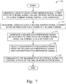
- Figure 7 illustrates an exemplary method 700 of adapting a pitch reference signal during partial load operation, according to one or more embodiments.
- the method 600 may be used in conjunction with other embodiments, such as being performed using the controller 205 depicted in Figure 5 .
- Method 700 begins at block 705, where the controller generates, using at least a first sensor signal, a first pitch reference signal for one or more rotor blades of a wind turbine during partial load operation.
- the first sensor signal comprises a rotational speed signal.
- the controller determines, using at least a second sensor signal, dynamic state information for a tower of the wind turbine.
- the second sensor signal comprises a tower acceleration signal.
- the dynamic state information comprises a tower frequency.
- the controller generates a second pitch reference signal by adapting the first pitch reference signal using the dynamic state information.
- generating the second pitch reference signal comprises generating a pitch reference offset signal using the dynamic state information.
- adapting the first pitch reference signal comprises summing the pitch reference offset signal with the first pitch reference signal.
- the controller selects a maximum pitch reference signal from the second pitch reference signal and a saturation pitch reference signal.
- the saturation pitch reference signal is the same as the first pitch reference signal. In other embodiments, the saturation pitch reference signal corresponds to a maximum power production level.
- the controller communicates the maximum pitch reference signal to control a pitch of the one or more rotor blades. In some embodiments, the controller communicates the maximum pitch reference signal with an external pitch controller. Method 700 ends following completion of block 745.
- aspects disclosed herein may be embodied as a system, method, or computer program product. Accordingly, aspects may take the form of an entirely hardware embodiment, an entirely software embodiment (including firmware, resident software, micro-code, etc.) or an embodiment combining software and hardware aspects that may all generally be referred to herein as a "circuit,” “module” or “system.” Furthermore, aspects may take the form of a computer program product embodied in one or more computer readable medium(s) having computer readable program code embodied thereon.
- the present invention may be a system, a method, and/or a computer program product.
- the computer program product may include a computer-readable storage medium (or media) (e.g., a portable computer diskette, a hard disk, a random access memory (RAM), a read-only memory (ROM), an erasable programmable read-only memory (EPROM or Flash memory), an optical fiber, a portable compact disc read-only memory (CD-ROM), an optical storage device, a magnetic storage device, or any suitable combination of the foregoing) having computer readable program instructions thereon for causing a processor to carry out aspects of the present invention.
- a computer-readable storage medium e.g., a portable computer diskette, a hard disk, a random access memory (RAM), a read-only memory (ROM), an erasable programmable read-only memory (EPROM or Flash memory), an optical fiber, a portable compact disc read-only memory (CD-ROM), an optical storage device, a magnetic storage device, or any suitable combination of
- each block in the flowchart or block diagrams may represent a module, segment or portion of code, which comprises one or more executable instructions for implementing the specified logical function(s).
- the functions noted in the block may occur out of the order noted in the figures. For example, two blocks shown in succession may, in fact, be executed substantially concurrently, or the blocks may sometimes be executed in the reverse order, depending upon the functionality involved.
Description
- Embodiments presented in this disclosure generally relate to wind turbines, and more specifically, to controlling power production of a wind turbine using dynamic state information for a tower of the wind turbine.
- Wind turbines typically comprise a tower and a nacelle located at the top of the tower. Taller towers are generally beneficial for producing greater amounts of electrical energy with the wind turbine, as a taller tower can support use of a larger diameter rotor and/or disposing the rotor further from negative effects on free wind flow that occur near the ground (such as ground drag and turbulence).
- Taller towers tend to be more flexible, which may give rise to dynamic interactions between tower movement and the rotor speed. For example, the wind speed (and aerodynamic torque) that is experienced by the rotor is influenced by the top motion of the tower. The power production of the wind turbine may be controlled by pitching the wind turbine blades to counter the aerodynamic torque. Pitching the wind turbine blades influences the forces acting on the tower and therefore the top motion of the tower, which in turn affects the experienced wind speed and the aerodynamic torque. In some cases, the dynamic interactions can introduce instability into the control of the wind turbine.
- Documents
WO2013/065323 andTW201416549 - The present disclosure presents a method comprising determining, using one or more sensor signals, dynamic state information for a tower of a wind turbine during power production, wherein the dynamic state information comprises a tower frequency. The method further comprises determining a first control loop gain value and a second control loop gain value using the tower frequency. The method further comprises generating, using the first control loop gain value and the second control loop gain value, one or more control signals for controlling a rotational speed of a rotor of the wind turbine.
- Beneficially, the method allows mitigation of an instability introduced into the wind turbine control that results from dynamic interactions occurring between the rotor and the tower. Further, by accounting for the effects of the rotor dynamics and/or the rotor-wind relation, the wind turbine may be tuned more aggressively resulting in greater power production than would be otherwise possible.
- Another embodiment described herein is a controller for a wind turbine, the controller comprising one or more computer processors, and a memory comprising computer-readable code that, when executed using the one or more computer processors, performs an operation. The operation comprises determining, using one or more sensor signals, dynamic state information for a tower of a wind turbine during power production, wherein the dynamic state information comprises a tower frequency. The operation further comprises determining a first control loop gain value and a second control loop gain value using the tower frequency. The operation further comprises generating, using the first control loop gain value and the second control loop gain value, one or more control signals for controlling a rotational speed of a rotor of the wind turbine.
- Beneficially, the controller allows mitigation of an instability introduced into the wind turbine control that results from dynamic interactions occurring between the rotor and the tower. Further, by accounting for the effects of the rotor dynamics and/or the rotor-wind relation, the wind turbine may be tuned more aggressively resulting in greater power production than would be otherwise possible.
- So that the manner in which the above recited features of the present disclosure can be understood in detail, a more particular description of the disclosure, briefly summarized above, may be had by reference to embodiments, some of which are illustrated in the appended drawings. It is to be noted, however, that the appended drawings illustrate only typical embodiments of this disclosure and are therefore not to be considered limiting of its scope, for the disclosure may admit to other equally effective embodiments.
-
Figure 1 illustrates a diagrammatic view of an exemplary wind turbine, according to one or more embodiments. -
Figure 2 is a block diagram of an exemplary wind turbine, according to one or more embodiments. -
Figure 3 is a block diagram illustrating controlling a rotational speed of a wind turbine rotor using dynamic state information of a wind turbine tower, according to one or more embodiments. -
Figure 4 is a block diagram illustrating determining control loop gain values using dynamic state information of a wind turbine tower, according to one or more embodiments. -
Figure 5 is a block diagram illustrating adapting a pitch reference signal during partial load operation, according to one or more embodiments. -
Figure 6 illustrates an exemplary method of controlling a rotational speed of a wind turbine rotor using dynamic state information of a wind turbine tower, according to one or more embodiments. -
Figure 7 illustrates an exemplary method of adapting a pitch reference signal during partial load operation, according to one or more embodiments. - To facilitate understanding, identical reference numerals have been used, where possible, to designate identical elements that are common to the figures. It is contemplated that elements disclosed in one embodiment may be beneficially utilized on other embodiments without specific recitation.
- Embodiments disclosed herein describe techniques for acquiring dynamic state information for a tower of a wind turbine during power production, and for controlling operation of the wind turbine based on the dynamic state information.
-
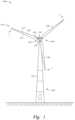
Figure 1 illustrates a diagrammatic view of anexemplary wind turbine 100. Although thewind turbine 100 is illustrated as a horizontal-axis wind turbine, the principles and techniques described herein may be applied to other wind turbine implementations, such as vertical-axis wind turbines. Thewind turbine 100 typically comprises atower 102 and anacelle 104 located at the top of thetower 102. Arotor 106 may be connected with thenacelle 104 through a low-speed shaft extending out of thenacelle 104. As shown, therotor 106 comprises threerotor blades 108 mounted on acommon hub 110 which rotate in a rotor plane, but therotor 106 may comprise any suitable number of blades, such as one, two, four, five, or more blades. The blades 108 (or airfoil) typically each have an aerodynamic shape with a leadingedge 112 for facing into the wind, atrailing edge 114 at the opposite end of a chord for theblades 108, atip 116, and aroot 118 for attaching to thehub 110 in any suitable manner. - For some embodiments, the
blades 108 may be connected to thehub 110 usingpitch bearings 120, such that eachblade 108 may be rotated around its longitudinal axis to adjust the blade's pitch. The pitch angle of ablade 108 relative to the rotor plane may be controlled by linear actuators, hydraulic actuators, or stepper motors, for example, connected between thehub 110 and theblades 108. - Although not depicted in
Figure 1 , alternate implementations of thewind turbine 100 may includemultiple rotors 106 connected with the nacelle 104 (or with multiple nacelles 104). In such implementations, thetower 102 may comprise one or more structural members that are configured to provide themultiple rotors 106 with a desired arrangement (e.g., with non-overlapping rotor planes). -
Figure 2 is a block diagram of anexemplary wind turbine 200, according to one or more embodiments. Thewind turbine 200 may be used in conjunction with other embodiments described herein. For example, thewind turbine 200 represents one possible implementation of thewind turbine 100 illustrated inFigure 1 . Thewind turbine 200 comprises acontroller 205 coupled with apitch controller 210 and with awind turbine generator 215. Thecontroller 205 is configured to receive one ormore sensor signals 280, and to generate one or more control signals for controlling a rotational speed of a rotor of thewind turbine 200. - The
controller 205 comprises one or more computer processors (or "processors") and a memory. The one or more processors represent any number of processing elements that each can include any number of processing cores. Some non-limiting examples of the one or more processors include a microprocessor, a digital signal processor (DSP), an application-specific integrated chip (ASIC), and a field programmable gate array (FPGA), or combinations thereof. - The memory can include volatile memory elements (such as random access memory), non-volatile memory elements (such as solid-state, magnetic, optical, or Flash-based storage), and combinations thereof. Moreover, the memory can be distributed across different mediums (e.g., network storage or external hard drives). The memory may include a plurality of "modules" for performing various functions described herein. In one embodiment, each module includes program code that is executable by one or more of the processors. However, other embodiments may include modules that are partially or fully implemented in hardware (i.e., circuitry) or firmware.
- The one or
more sensor signals 280 may comprise any suitable information related to rotor dynamics and/or tower dynamics. In one non-limiting example, the one ormore sensor signals 280 comprise a generator speed of thewind turbine generator 215 and a tower acceleration. - In some embodiments, the
controller 205 comprises a fullload control module 225, a partialload control module 230, and atower damping module 235. The fullload control module 225 is configured to control power production by thewind turbine generator 215 during wind conditions that are suitable for producing at least a rated power of thewind turbine 200. The partialload control module 230 is configured to control power production by thewind turbine generator 215 during wind conditions that are not suitable for producing the rated power of thewind turbine 200. For example, the fullload control module 225 may control power production when a measured wind speed is greater than or equal to a rated wind speed of thewind turbine 200, and the partialload control module 230 may control power production when the measured wind speed is less than the rated wind speed. - The
wind turbine generator 215 may have any suitable implementation, such as a synchronous generator, an induction generator, a permanent magnet generator, and so forth. Further, thewind turbine generator 215 may be configured as a doubly-fed induction generator (DFIG), for full-scale power conversion, and so forth. - In some embodiments, the full
load control module 225 operates to control a pitch of the one or more rotor blades to avoid undesired conditions of thewind turbine 200. For example, the fullload control module 225 may pitch rotor blades out of the wind to prevent thewind turbine generator 215 from an overspeeding condition. In some embodiments, the partialload control module 230 operates to control a pitch of the one or more rotor blades to an optimal pitch angle. Although thewind turbine generator 215 is unable to produce the rated power while operating in the partial load control regime, the optimal pitch angle permits a maximum amount of energy to be captured from the wind while increasing the speed of thewind turbine generator 215. As mentioned above, thecontroller 205 may transition from the partial load control regime to the full load control regime when the measured wind speed reach a rated wind speed of the wind turbine. - In some embodiments, the full
load control module 225 and the partialload control module 230 may be implemented within arotor speed controller 220. Therotor speed controller 220 is generally responsive to rotor dynamics and may be insensitive or agnostic to tower dynamics. Therotor speed controller 220 may further comprise switching logic configured to determine when to switch between the respective control regimes provided by the fullload control module 225 and the partialload control module 230. In some embodiments, the switching logic receives the measured wind speed as an input and may receive information from one or other wind conditions and/or wind turbine conditions. - The
tower damping module 235 is configured to determine dynamic state information (state information 240) for a tower of thewind turbine 200, and to generate one or more control signals for controlling the rotational speed of the rotor. In some embodiments, thestate information 240 comprises one or more of acceleration information, velocity information, and position information for the tower along one or more suitable dimensions. In some embodiments, thesensors 250 include an accelerometer arranged at a reference location of the tower, and the one or more sensor signals 280 comprises acceleration information provided by the accelerometer. For example, the accelerometer may be arranged at a top of the tower, although other locations are also possible. In some embodiments, thetower damping module 235 is configured to generate velocity information and/or position information using the received acceleration information. In other embodiments, thesensors 250 may comprise one or more sensors that are configured to directly measure the velocity information and/or the position information for the tower, which may be provided to thetower damping module 235. - In some embodiments, the
state information 240 comprises atower frequency 245 along one or more suitable dimensions. Thetower frequency 245 may comprise a fundamental frequency of the tower. Some non-limiting examples of the suitable dimensions include a fore-and-aft dimension that generally corresponds to the direction of the wind at the wind turbine 200 (e.g., assuming the rotor is yawed to align with the direction of the wind), and a side-to-side dimension that is generally orthogonal to the direction of the wind. In another example involving a wind turbine comprising multiple rotors, thetower frequency 245 may comprise a torsion about the tower. - In some embodiments, the
tower damping module 235 is configured to determine thetower frequency 245 using at least one of velocity information and position information. For example, thetower damping module 235 may determine frequency information (or "frequency content") that is included in the position information, e.g., by performing a Fast Fourier Transform (FFT) on the position information. Other frequency analysis techniques are also possible. Generally, agreater tower frequency 245 corresponds to a stiffer tower, and alesser tower frequency 245 corresponds to a more flexible tower. In one non-limiting example, determining thetower frequency 245 may be dynamically performed by thetower damping module 235 during power production of the wind turbine. In another non-limiting example, determining thetower frequency 245 may be performed by thetower damping module 235 during a shutdown period of the wind turbine. In another non-limiting example, determining thetower frequency 245 may be performed during a commissioning process for the wind turbine. In another non-limiting example, thetower frequency 245 may be provided to thetower damping module 235 via user input. - As mentioned above, the
tower damping module 235 is configured to generate one or more control signals using thestate information 240. In some embodiments, the rotor speed controller 220 (more specifically, a selected one of the fullload control module 225 and the partial load control module 230) is configured to generate apitch reference signal 255, and thetower damping module 235 is configured to produce a pitch reference offsetsignal 260 that is combined with thepitch reference signal 255. In some embodiments, thepitch reference signal 255 corresponds to a commanded power production of the wind turbine, whether from the fullload control module 225 or the partialload control module 230. In some embodiments, thecontroller 205 may add thepitch reference signal 255 with the pitch reference offsetsignal 260 at anadder 265, which outputs apitch reference signal 270. - In some embodiments, the
controller 205 provides thepitch reference signal 270 to apitch controller 210 to control a pitch of one or more rotor blades of thewind turbine 200. In turn, thepitch controller 210 outputs pitchvalues 275 to control the wind turbine generator 215 (more specifically, a rotational speed of the rotor). In some embodiments, thepitch controller 210 is implemented separate from thecontroller 205. In alternate embodiments, the functionality of thepitch controller 210 may be integrated into thecontroller 205. - Thus, with the functionality provided by the
tower damping module 235, thecontroller 205 can be responsive to rotor dynamics, tower dynamics, and a rotor-wind relation. In some embodiments, the rotor-wind relation comprises an effective wind speed experienced at the rotor, which may be represented as a difference between the free wind speed and a velocity of the tower. Further, by accounting for the effects of the rotor dynamics and/or the rotor-wind relation using thetower damping module 235 allows the fullload control module 225 to be tuned more aggressively than would be otherwise possible. Still further, although described above in terms of tower dynamics, it will be noted that the techniques discussed with relation to thetower damping module 235 may be applicable to other types of structures to mitigate torsional instabilities. -
Figure 3 is a block diagram 300 illustrating controlling a rotational speed of a wind turbine rotor using dynamic state information of a wind turbine tower, according to one or more embodiments. The features illustrated in the block diagram 300 may be used in conjunction with other embodiments described herein, such as thecontroller 205 depicted inFigure 2 . - The
rotor speed controller 220 is configured to receive a generator speed ω from arotor speed sensor 350, and a reference generator speed ωref. Asubtractor 340 of therotor speed controller 220 generates an error signal based on a difference of the generator speed ω and the reference generator speed ωref. A proportional-integral (PI)controller 345 generates apitch reference signal 255 using the error signal. - The
tower damping module 235 is configured to receive a tower acceleration αTower from atower accelerometer 355. Thetower damping module 235 comprises afilter module 302 configured to filter the tower acceleration αTower to produce filteredacceleration information 304. Afirst integrator 305 is configured to producevelocity information 310 from the filteredacceleration information 304, and asecond integrator 315 is configured to produceposition information 320 from thevelocity information 310. As discussed above, in other embodiments, thesensors 250 may comprise one or more sensors that are configured to directly measure thevelocity information 310 and/or theposition information 320. - The
filter module 302 may comprise one or more filtering stages to produce the filteredacceleration information 304. In some embodiments, thefilter module 302 may be configured to remove low-frequency components from the tower acceleration αTower, such as direct current (DC) components. In some embodiments, thefilter module 302 may be configured to perform anti-aliasing of the tower acceleration αTower. In some embodiments, thefilter module 302 may be configured to filter frequency components associated with rotation of the rotor, such as a 3P frequency. Any suitable cutoff frequencies may be selected for the various filtering stages. Further, the filtering stages may be adaptively updated during operation of the wind turbine, e.g., based on wind conditions. - In some embodiments, the
first integrator 305 and/or thesecond integrator 310 may be implemented as "leaky" integrators (e.g., a first-order low-pass filter (LPF) having a cutoff frequency significantly less than frequencies of interest). For example, the cutoff frequencies for thefirst integrator 305 and/or thesecond integrator 310 may be selected to prevent introducing too much phase lead at frequencies near thetower frequency 245. - A
first amplifier 325 of thetower damping module 235 has a first control loop gain value (i.e., velocity gain Av) to be applied to thevelocity information 310. Asecond amplifier 330 of thetower damping module 235 has a second control loop gain value (i.e., position gain Ap) to be applied to theposition information 320. Anadder 335 sums the outputs of thefirst amplifier 325 and thesecond amplifier 330 to produce the pitch reference offsetsignal 260. Theadder 265 receives thepitch reference signal 255 and the pitch reference offsetsignal 260, and outputs thepitch reference signal 270. - In some embodiments, the first control loop gain value and/or the second control loop gain value may be dynamically updated using the dynamic state information for the tower of the wind turbine. For example, at least one control loop gain value may be determined using a determined tower frequency.
- As shown, the
tower damping module 235 is configured to output a pitch reference offsetsignal 260 having a velocity component based on thevelocity information 310 and a position component based on theposition information 320. In one alternate implementation, the pitch reference offsetsignal 260 may have only one of the velocity component and the position component. In another alternate implementation, the pitch reference offsetsignal 260 may have an acceleration component based on the tower acceleration αTower. The acceleration component may be in addition to, or may be separate from, the velocity component and/or the position component. - In some embodiments, the
tower damping module 235 has a predefined tuning specific to the wind turbine platform. The predefined tuning may comprise a predefined first set of values (e.g., the velocity gain Av and/or the position gain Ap), which may then be adaptively updated during operation of the wind turbine. In this way, thetower damping module 235 may be implemented for various wind turbines independent of their geographic location. Stated another way, thetower damping module 235 does not require a site-specific tuning to be performed prior to the operation of the wind turbine. -
Figure 4 is a block diagram 400 illustrating determining control loop gain values using dynamic state information of a wind turbine tower, according to one or more embodiments. The features illustrated in the block diagram 400 may be used in conjunction with other embodiments described herein, such as implemented in thetower damping module 325 depicted inFigure 3 . Further, the features illustrated in the block diagram 400 may be used during full load operation and/or during partial load operation of the wind turbine. - In some embodiments, an
adaptation module 405 is configured to determine at least one control loop gain value using a tower frequency fTower. As discussed above, the tower frequency fTower may be determined using frequency information included in the position information. Theadaptation module 405 comprises a firstgain scheduling module 415 configured to schedule a first control loop gain value (i.e., velocity gain Av), and a secondgain scheduling module 420 configured to schedule a second control loop gain value (i.e., position gain Ap). - As shown, the first control loop gain value and the second control loop gain value are each selected within a range between zero (0) and one (1). Alternate implementations may schedule the first control loop gain value and/or the second control loop gain value from any suitable range(s). Further, the range for the first control loop gain value and the range for the second control loop gain value need not be the same.
- For values of the tower frequency fTower that are less than a first threshold frequency foff,v, the velocity gain Av has a zero value. For values of the tower frequency fTower that are greater than a second threshold frequency fon,v, the velocity gain Av has a one value. For values of the tower frequency fTower between the first threshold frequency foff,v and the second threshold frequency fon,v, the velocity gain Av has values adapted according to a predefined function. Thus, in some embodiments, the
adaptation module 405 is configured to, responsive to determining that the tower frequency fTower is less than a first threshold frequency foff,v, deactivate or detune a first control loop associated with the first control loop gain value (velocity gain Av). Beneficially, certain effects of the velocity-based feedback can be mitigated by deactivating or detuning the first control loop, such as mitigating a destabilizing effect when employed with relatively flexible towers. - For values of the tower frequency fTower that are less than a first threshold frequency fon,p, the position gain Ap has a one value. For values of the tower frequency fTower that are greater than a second threshold frequency foff,p, the position gain Ap has a zero value. For values of the tower frequency fTower between the first threshold frequency fon,p and the second threshold frequency foff,p, the position gain Ap has values adapted according to a predefined function. Thus, in some embodiments, the
adaptation module 405 is configured to, responsive to determining that the tower frequency fTower is greater than a second threshold frequency foff,p, deactivate or detune a second control loop associated with the second control loop gain value (position gain Ap). - In some embodiments, the predefined functions associated with the velocity gain Av and the position gain Ap are substantially linear. However, any other suitable functions are also contemplated (e.g., quadratic).
- In some embodiments, an
optional adaptation module 410 is configured to receive the first control loop gain value (velocity gain Av) and the second control loop gain value (position gain Ap), and to generate adapted control loop gain values A'v, A'p to apply to the respective control loops. In this way, theadaptation module 410 may mitigate certain effects of the velocity-based feedback and/or position-based feedback. For example, theadaptation module 410 may limit application of control loop gain values to mitigate wear on the pitch system. Theadaptation module 410 comprises a firstgain scheduling module 425 configured to schedule a first adapted gain value, and a secondgain scheduling module 430 configured to schedule a second adapted gain value. - For values of a mean tower acceleration αTower,RMS that are less than a first threshold acceleration RMSoff,v, the first
gain scheduling module 425 outputs a zero value. For values of the mean tower acceleration aTower,RMS that are greater than a second threshold acceleration RMSon,v, the firstgain scheduling module 425 outputs a one value. For values of the mean tower acceleration αTower,RMS between the first threshold acceleration RMSoff,v and the second threshold acceleration RMSon,v, the firstgain scheduling module 425 outputs values adapted according to a predefined function. The value output by the firstgain scheduling module 425 and the first control loop gain value (velocity gain Av) are compared at aminimum block 435 and the minimum value is output as the adapted control loop gain value A'v. - Thus, in some embodiments, the first
gain scheduling module 425 is configured to enable, disable, or otherwise limit the functionality of the firstgain scheduling module 415. For example, the firstgain scheduling module 425 may mitigate wear on the pitch system by enabling the firstgain scheduling module 415 only when oscillations of the tower exceed a predefined amplitude. - For values of the mean tower acceleration αTower,RMS that are less than a first threshold acceleration RMSoff,p, the second
gain scheduling module 430 outputs a zero value. For values of the mean tower acceleration αTower,RMS that are greater than a second threshold acceleration RMSon,p, the secondgain scheduling module 430 outputs a one value. For values of the mean tower acceleration αTower,RMS between the first threshold acceleration RMSoff,p and the second threshold acceleration RMSon,p, the secondgain scheduling module 430 outputs values adapted according to a predefined function. The value output by the secondgain scheduling module 430 and the second control loop gain value (position gain Ap) are compared at aminimum block 440 and the minimum value is output as the adapted control loop gain value A'p. - Thus, in some embodiments, the second
gain scheduling module 430 is configured to enable, disable, or otherwise limit the functionality of the secondgain scheduling module 420. For example, the firstgain scheduling module 425 may be used to prevent application of small values of the pitch reference offset signal to be applied during full load operation. - Although not explicitly shown, in some embodiments, the
adaptation module 405 may comprise an additional gain scheduling module that affects the position gain Ap as a function of the operating point of the wind turbine. The full load control module (e.g., the fullload control module 225 ofFigure 2 ) may include a comparable functionality. The output values from the additional gain scheduling module need not be bound to a zero-to-one range but may have any suitable values. -
Figure 5 is a block diagram 500 illustrating adapting a pitch reference signal during partial load operation, according to one or more embodiments. The features illustrated in the block diagram 500 may be used in conjunction with other embodiments described herein, such as implemented in thecontroller 205 depicted inFigure 2 . - The partial
load control module 230 is configured to produce thepitch reference signal 255. In some embodiments, thepitch reference signal 255 reflects a maximum collective pitch angle from a plurality of pitch angles calculated by the partialload control module 230 according to one or more predefined parameters. For example, the partialload control module 230 may calculate a first pitch angle corresponding to a maximum (or other desired) power production level, a second pitch angle corresponding to a thrust limitation parameter, a third pitch angle corresponding to a noise limitation parameter, a fourth pitch angle corresponding to a yaw error parameter, and so forth. - The
tower damping module 235 is configured to produce the pitch reference offsetsignal 260, and theadder 265 is configured to output thepitch reference signal 510 to asaturation block 505. Thepitch reference signal 510 and a saturationpitch reference signal 515 are compared at thesaturation block 505 and the maximum value is output as a maximumpitch reference signal 520. Use of the maximumpitch reference signal 520 may be beneficial to prevent a rotor blade stall, to reduce noise emissions, and so forth. - In some embodiments, the saturation
pitch reference signal 515 comprises thepitch reference signal 255. In such a case, thecontroller 205 allows the rotor blades only to be pitched out of the wind from the pitch angle commanded by thepitch reference signal 255. Stated another way, the value of the maximumpitch reference signal 520 will not be less than thepitch reference signal 255 prior to application of the tower damping functionality. In other embodiments, the saturationpitch reference signal 515 comprises a pitch reference signal corresponding to a maximum power production level for an operation point of the wind turbine. The maximum power production level generally corresponds to a pitch angle at which the wind turbine extracts as much power as possible from the wind. In this case, the saturationpitch reference signal 515 may further comprise a pitch offset. For such an implementation, thecontroller 250 allows the rotor blades to be pitched into the wind depending on the operation point of the wind turbine (e.g., during thrust-limited operation). Stated another way, for an implementation of the partialload control module 230 comprising a first pitch angle corresponding to the maximum power production level and at least a second pitch angle corresponding to another operational parameter (such as thrust limitation, noise limitation, yaw error, etc.), the value of the maximumpitch reference signal 520 may be less than thepitch reference signal 255 when the partialload control module 230 is controlled according to the second pitch angle. Other implementations of thecontroller 205 may include any other suitable signals as the saturationpitch reference signal 515. - During partial load operation, the
tower damping module 235 may suffer from estimation errors for frequencies that are lower than thetower frequency 245. These estimation errors may be amplified when estimating velocity information and position information from measured acceleration information, and may be reflected in the pitch reference offsetsignal 260. The estimation errors may not have a substantial effect during full load operation, as the pitch reference offsetsignal 260 can be viewed as a disturbance occurring between thecontroller 205 and the pitch system. However, the estimation errors may have a more substantial effect during partial load operation. - Typically, the partial
load control module 230 may control rotor speed by regulating a power reference, while the corresponding pitch angle may be determined via look-up tables and/or relations to quantities measured from one or more sensor signals 280 (e.g., rotor speed, wind speed, etc.). During partial load operation, as there is not a closed-loop control for the pitch angle (e.g., including an integrator), the low-frequency variations introduced by thetower damping module 235 may be input directly into the commanded pitch angle of the pitch reference offsetsignal 260, which causes low-frequency thrust variations and may hinder performance of the wind turbine. - To mitigate the amplification of low-frequency content that may occur during partial load operation, in some embodiments the
controller 205 is configured to retune filter(s) of the tower damping module 235 (e.g., thefilter module 302, thefirst integrator 305, and/or thesecond integrator 310 ofFigure 3 ). For example, thecontroller 205 may retune one or more high-pass filters (HPFs) of thetower damping module 235 to be closer to the operating region to mitigate low-frequency content at the expense of phase lead at frequencies near thetower frequency 245. However, in some cases the retuned filter(s) may correspond to reduced performance during full load operation. Therefore, in some embodiments, thecontroller 205 may retune the filter(s) responsive to transitioning into partial load operation. In some embodiments, thecontroller 205 may retune the filter(s) (e.g., returning the filter(s) to their original tuning) responsive to transitioning into full load operation. -
Figure 6 illustrates anexemplary method 600 of controlling a rotational speed of a wind turbine rotor using dynamic state information of a wind turbine tower, according to one or more embodiments. Themethod 600 may be used in conjunction with other embodiments, such as being performed using thecontroller 205 depicted inFigure 2 . -
Method 600 begins at block 605, where the controller determines, using one or more sensor signals, dynamic state information for a tower of a wind turbine during power production. In some embodiments, the dynamic state information comprises a tower frequency. Atblock 615, the controller determines at least one control loop gain value using the tower frequency. In some embodiments, the controller determines a first control loop gain value to be applied to velocity information corresponding to a reference location of the tower, and a second control loop gain value to be applied to position information corresponding to the reference location. Atblock 625, the controller generates, using the at least one control loop gain value, one or more control signals for controlling a rotational speed of a rotor of the wind turbine. In some embodiments, the one or more control signals comprises a pitch reference signal to control a pitch of one or more rotor blades of the wind turbine.Method 600 ends following completion ofblock 625. -
Figure 7 illustrates anexemplary method 700 of adapting a pitch reference signal during partial load operation, according to one or more embodiments. Themethod 600 may be used in conjunction with other embodiments, such as being performed using thecontroller 205 depicted inFigure 5 . -
Method 700 begins atblock 705, where the controller generates, using at least a first sensor signal, a first pitch reference signal for one or more rotor blades of a wind turbine during partial load operation. In some embodiments, the first sensor signal comprises a rotational speed signal. Atblock 715, the controller determines, using at least a second sensor signal, dynamic state information for a tower of the wind turbine. In some embodiments, the second sensor signal comprises a tower acceleration signal. In some embodiments, the dynamic state information comprises a tower frequency. - At
block 725, the controller generates a second pitch reference signal by adapting the first pitch reference signal using the dynamic state information. In some embodiments, generating the second pitch reference signal comprises generating a pitch reference offset signal using the dynamic state information. In some embodiments, adapting the first pitch reference signal comprises summing the pitch reference offset signal with the first pitch reference signal. - At
block 735, the controller selects a maximum pitch reference signal from the second pitch reference signal and a saturation pitch reference signal. In some embodiments, the saturation pitch reference signal is the same as the first pitch reference signal. In other embodiments, the saturation pitch reference signal corresponds to a maximum power production level. - At
block 745, the controller communicates the maximum pitch reference signal to control a pitch of the one or more rotor blades. In some embodiments, the controller communicates the maximum pitch reference signal with an external pitch controller.Method 700 ends following completion ofblock 745. - In the preceding, reference is made to embodiments presented in this disclosure. However, the scope of the present disclosure is not limited to specific described embodiments. Instead, any combination of the features and elements provided above, whether related to different embodiments or not, is contemplated to implement and practice contemplated embodiments. Furthermore, although embodiments disclosed herein may achieve advantages over other possible solutions or over the prior art, whether or not a particular advantage is achieved by a given embodiment is not limiting of the scope of the present disclosure. Thus, the aspects, features, embodiments, and advantages described herein are merely illustrative and are not considered elements or limitations of the appended claims except where explicitly recited in a claim(s).
- As will be appreciated by one skilled in the art, the embodiments disclosed herein may be embodied as a system, method, or computer program product. Accordingly, aspects may take the form of an entirely hardware embodiment, an entirely software embodiment (including firmware, resident software, micro-code, etc.) or an embodiment combining software and hardware aspects that may all generally be referred to herein as a "circuit," "module" or "system." Furthermore, aspects may take the form of a computer program product embodied in one or more computer readable medium(s) having computer readable program code embodied thereon.
- The present invention may be a system, a method, and/or a computer program product. The computer program product may include a computer-readable storage medium (or media) (e.g., a portable computer diskette, a hard disk, a random access memory (RAM), a read-only memory (ROM), an erasable programmable read-only memory (EPROM or Flash memory), an optical fiber, a portable compact disc read-only memory (CD-ROM), an optical storage device, a magnetic storage device, or any suitable combination of the foregoing) having computer readable program instructions thereon for causing a processor to carry out aspects of the present invention.
- Aspects of the present disclosure are described with reference to flowchart illustrations and/or block diagrams of methods, apparatus (systems) and computer program products according to embodiments presented in this disclosure. It will be understood that each block of the flowchart illustrations and/or block diagrams, and combinations of blocks in the flowchart illustrations and/or block diagrams, can be implemented by computer program instructions. These computer program instructions may be provided to a processor of a general purpose computer, special purpose computer, or other programmable data processing apparatus to produce a machine, such that the instructions, which execute via the processor of the computer or other programmable data processing apparatus, create means for implementing the functions/acts specified in the flowchart and/or block diagram block or blocks.
- The flowchart and block diagrams in the Figures illustrate the architecture, functionality and operation of possible implementations of systems, methods and computer program products according to various embodiments. In this regard, each block in the flowchart or block diagrams may represent a module, segment or portion of code, which comprises one or more executable instructions for implementing the specified logical function(s). It should also be noted that, in some alternative implementations, the functions noted in the block may occur out of the order noted in the figures. For example, two blocks shown in succession may, in fact, be executed substantially concurrently, or the blocks may sometimes be executed in the reverse order, depending upon the functionality involved. It will also be noted that each block of the block diagrams and/or flowchart illustration, and combinations of blocks in the block diagrams and/or flowchart illustration, can be implemented by special purpose hardware-based systems that perform the specified functions or acts, or combinations of special purpose hardware and computer instructions.
- In view of the foregoing, the scope of the present disclosure is determined by the claims that follow.
Claims (9)
- A method comprising:
determining (605), using one or more sensor signals, dynamic state information for a tower of a wind turbine during power production, wherein the dynamic state information comprises determining velocity information and position information corresponding to a reference location of the tower and a tower frequency, the tower frequency depends from at least one of the velocity information and the position information;determining (615) a first control loop gain value and a second control loop gain value using the tower frequency; andgenerating (625), using the first control loop gain value and the second control loop gain value, one or more control signals for controlling a rotational speed of a rotor of the wind turbine,the one or more control signals comprises:
generating a pitch reference signal to control a pitch of one or more rotor blades of the wind turbine, wherein generating the pitch reference signal comprises applying the first control loop gain value to the velocity information and applying the second control loop gain value to the position information. - The method of claim 1, further comprising:
responsive to determining that the tower frequency is less than a first threshold frequency, deactivating or detuning a first control loop associated with the first control loop gain value. - The method of claims 1 or 2, further comprising:
responsive to determining that the tower frequency is greater than a second threshold frequency, deactivating or detuning a second control loop associated with the second control loop gain value. - The method of any of the previous claims, wherein generating the pitch reference signal comprises:generating a first pitch reference signal corresponding to a commanded power production of the wind turbine;generating a pitch reference offset signal using the dynamic state information; andadding the pitch reference offset signal to the first pitch reference signal to generate the pitch reference signal.
- A controller (205) for a wind turbine (100), the controller comprising:one or more computer processors; anda memory comprising computer-readable code that, when executed using the one or more computer processors, performs an operation comprising:determining, using one or more sensor signals (250), dynamic state information (240) for a tower of a wind turbine during power production, wherein the dynamic state information comprises determining velocity information and position information corresponding to a reference location of the tower and a tower frequency, the tower frequency depends from at least one of the velocity information and the position information;determining a first control loop gain value (325) and a second control loop gain value (330) using the tower frequency; andgenerating, using the first control loop gain value and the second control loop gain value, one or more control signals (270) for controlling a rotational speed of a rotor of the wind turbine,the one or more control signals comprises:
generating a pitch reference signal to control a pitch of one or more rotor blades of the wind turbine, wherein generating the pitch reference signal comprises applying the first control loop gain value to the velocity information and applying the second control loop gain value to the position information. - The controller of claim 5, further comprising:
responsive to determining that the tower frequency is less than a first threshold frequency, deactivating or detuning a first control loop associated with the first control loop gain value. - The controller of claims 5 or 6, further comprising:
responsive to determining that the tower frequency is greater than a second threshold frequency, deactivating or detuning a second control loop associated with the second control loop gain value. - The controller of any of the previous claims, wherein generating the pitch reference signal comprises:generating a first pitch reference signal corresponding to a commanded power production of the wind turbine;generating a pitch reference offset signal using the dynamic state information; andadding the pitch reference offset signal to the first pitch reference signal to generate the pitch reference signal.
- A wind turbine (100) comprising:a tower (102);a rotor (103);one or more sensors (250) configured to generate one or more sensor signals; andthe controller (205) according to claim 5.
Applications Claiming Priority (2)
| Application Number | Priority Date | Filing Date | Title |
|---|---|---|---|
| DKPA201770943 | 2017-12-14 | ||
| PCT/DK2018/050320 WO2019114897A1 (en) | 2017-12-14 | 2018-12-04 | Tower damping in wind turbine power production |
Publications (2)
| Publication Number | Publication Date |
|---|---|
| EP3724488A1 EP3724488A1 (en) | 2020-10-21 |
| EP3724488B1 true EP3724488B1 (en) | 2023-02-01 |
Family
ID=64663996
Family Applications (1)
| Application Number | Title | Priority Date | Filing Date |
|---|---|---|---|
| EP18815940.4A Active EP3724488B1 (en) | 2017-12-14 | 2018-12-04 | Tower damping during power production of a wind turbine |
Country Status (5)
| Country | Link |
|---|---|
| US (1) | US11319925B2 (en) |
| EP (1) | EP3724488B1 (en) |
| CN (1) | CN111712632B (en) |
| ES (1) | ES2937911T3 (en) |
| WO (1) | WO2019114897A1 (en) |
Families Citing this family (3)
| Publication number | Priority date | Publication date | Assignee | Title |
|---|---|---|---|---|
| ES2937911T3 (en) | 2017-12-14 | 2023-04-03 | Vestas Wind Sys As | Tower damping during power production from a wind turbine |
| EP3667074A1 (en) * | 2018-12-13 | 2020-06-17 | Siemens Gamesa Renewable Energy A/S | Device and method of damping front and backward movements of a tower of a wind turbine |
| CN111980869B (en) * | 2020-09-03 | 2021-07-06 | 明阳智慧能源集团股份公司 | Decoupling method for rotating speed of floating type double-impeller wind turbine generator and floating platform motion control |
Family Cites Families (32)
| Publication number | Priority date | Publication date | Assignee | Title |
|---|---|---|---|---|
| US4420692A (en) * | 1982-04-02 | 1983-12-13 | United Technologies Corporation | Motion responsive wind turbine tower damping |
| US4435647A (en) * | 1982-04-02 | 1984-03-06 | United Technologies Corporation | Predicted motion wind turbine tower damping |
| CA2557396C (en) * | 2004-02-27 | 2010-12-21 | Mitsubishi Heavy Industries, Ltd. | Wind turbine generator, active damping method thereof, and windmill tower |
| US7317260B2 (en) * | 2004-05-11 | 2008-01-08 | Clipper Windpower Technology, Inc. | Wind flow estimation and tracking using tower dynamics |
| US7342323B2 (en) * | 2005-09-30 | 2008-03-11 | General Electric Company | System and method for upwind speed based control of a wind turbine |
| US7488155B2 (en) * | 2005-11-18 | 2009-02-10 | General Electric Company | Method and apparatus for wind turbine braking |
| DE102006001613B4 (en) * | 2006-01-11 | 2008-01-31 | Repower Systems Ag | Method for operating a wind turbine and wind turbine |
| JP4814644B2 (en) | 2006-02-01 | 2011-11-16 | 富士重工業株式会社 | Wind power generator |
| WO2008031434A2 (en) * | 2006-09-14 | 2008-03-20 | Vestas Wind Systems A/S | Method for controlling a wind turbine connected to the utility grid, wind turbine and wind park |
| ATE502208T1 (en) * | 2006-12-28 | 2011-04-15 | Clipper Windpower Inc | WIND TURBINE DAMPING OF TOWER RESONANCE MOTION AND SYMMETRIC BLADE MOTION USING ESTIMATION METHODS |
| ES2552162T5 (en) | 2007-11-26 | 2020-03-02 | Siemens Ag | Wind turbine tower vibration damping method and tilt control system |
| DE102007063082B4 (en) * | 2007-12-21 | 2010-12-09 | Repower Systems Ag | Method for operating a wind energy plant |
| ES2327486B1 (en) * | 2008-03-14 | 2010-07-14 | Ingeteam Energy, S.A. | METHOD OF OPERATION OF A WIND TURBINE TO GUARANTEE PRIMARY OR SECONDARY REGULATION IN AN ELECTRICAL NETWORK. |
| EP2123906A1 (en) | 2008-05-21 | 2009-11-25 | Siemens Aktiengesellschaft | Method and apparatus for damping tower oscillation in a wind turbine |
| EP2354538A1 (en) * | 2010-02-01 | 2011-08-10 | Lm Glasfiber A/S | A method of in situ calibrating load sensors of a wind turbine blade |
| US20120049516A1 (en) * | 2010-08-25 | 2012-03-01 | Vestas Wind Systems A/S | Method, system, and computer program product to optimize power plant output and operation |
| US20110223006A1 (en) * | 2010-12-06 | 2011-09-15 | Friedrich Loh | System, device, and method for noise-based operation of wind turbines |
| EP2655875B1 (en) * | 2010-12-21 | 2015-11-18 | Vestas Wind Systems A/S | Control method for a wind turbine |
| JP6187935B2 (en) * | 2011-11-04 | 2017-08-30 | 国立研究開発法人 海上・港湾・航空技術研究所 | Control device for floating offshore wind power generation facility |
| EP2786017B1 (en) * | 2011-11-21 | 2017-04-12 | Vestas Wind Systems A/S | A shutdown controller for a wind turbine and a method of shutting down a wind turbine |
| EP2685093B1 (en) * | 2012-07-10 | 2016-06-29 | Alstom Wind, S.L.U. | Wind turbine stabilization |
| TWI545256B (en) * | 2012-10-29 | 2016-08-11 | 行政院原子能委員會核能研究所 | Device of actively absorbing vibration for wind power tower |
| EP2803853B1 (en) * | 2013-05-17 | 2015-09-02 | Siemens Aktiengesellschaft | Damping wind turbine tower oscillations using gyroscopic forces |
| KR101822535B1 (en) * | 2013-05-30 | 2018-01-26 | 엠에이치아이 베스타스 오프쇼어 윈드 에이/에스 | Tilt damping of a floating wind turbine |
| EP2811359B1 (en) * | 2013-06-06 | 2018-08-08 | The Boeing Company | Method and system for aircraft speed control |
| CN105874196B (en) * | 2013-11-29 | 2020-11-24 | 维斯塔斯风力系统集团公司 | Wind turbine system, pitch controller thereof and method for stabilizing power output |
| WO2016150442A1 (en) * | 2015-03-20 | 2016-09-29 | Vestas Wind Systems A/S | Damping oscillations in a wind turbine |
| DK3286430T3 (en) * | 2015-04-23 | 2020-04-06 | Envision Energy Denmark Aps | Method for correcting imbalance in the rotor and wind turbine thereof |
| JP6554368B2 (en) * | 2015-09-10 | 2019-07-31 | 株式会社日立製作所 | Wind power generation system or control method of wind power generation system |
| CN109072872B (en) * | 2016-02-24 | 2020-02-21 | 维斯塔斯风力系统集团公司 | Damping of wind turbine oscillations |
| ES2937911T3 (en) | 2017-12-14 | 2023-04-03 | Vestas Wind Sys As | Tower damping during power production from a wind turbine |
| CN112696317A (en) * | 2019-10-22 | 2021-04-23 | 通用电气公司 | System and method for controlling wind turbines based on collective pitch offsets |
-
2018
- 2018-12-04 ES ES18815940T patent/ES2937911T3/en active Active
- 2018-12-04 CN CN201880089161.9A patent/CN111712632B/en active Active
- 2018-12-04 US US16/954,186 patent/US11319925B2/en active Active
- 2018-12-04 WO PCT/DK2018/050320 patent/WO2019114897A1/en unknown
- 2018-12-04 EP EP18815940.4A patent/EP3724488B1/en active Active
Also Published As
| Publication number | Publication date |
|---|---|
| US11319925B2 (en) | 2022-05-03 |
| CN111712632B (en) | 2023-04-25 |
| CN111712632A (en) | 2020-09-25 |
| EP3724488A1 (en) | 2020-10-21 |
| ES2937911T3 (en) | 2023-04-03 |
| WO2019114897A1 (en) | 2019-06-20 |
| US20210164441A1 (en) | 2021-06-03 |
Similar Documents
| Publication | Publication Date | Title |
|---|---|---|
| EP3724489B1 (en) | Tower damping in wind turbine power production | |
| EP3724488B1 (en) | Tower damping during power production of a wind turbine | |
| JP6228914B2 (en) | System for minimizing yaw torque required to control power output in a two-bladed swing hinge wind turbine controlling power output by yawing | |
| US20180066630A1 (en) | Damping oscillations in a wind turbine | |
| US20220220936A1 (en) | Reduction of edgewise vibrations using blade load signal | |
| WO2019163325A1 (en) | Wind power generation device and control method for same | |
| JP5550501B2 (en) | Horizontal axis windmill | |
| US20220220937A1 (en) | Reduction of edgewise vibrations using torsional vibration signal | |
| EP3966449A1 (en) | Wind turbine control using predicted steady-state deflection | |
| JP6933990B2 (en) | Wind power generators and their control methods | |
| US11846270B2 (en) | Control method and device of a wind park | |
| CN116964318A (en) | Reducing edge vibration using blade load signals | |
| TWI702339B (en) | Wind power generation device and control method thereof | |
| WO2023088432A1 (en) | Controller for a wind turbine | |
| WO2023088416A1 (en) | Controller for a wind turbine | |
| DK181365B1 (en) | Controller, method, apparatus, and computer program product for controlling a wind turbine | |
| DK201570134A1 (en) | Dynamic range control for wind turbine damping system |
Legal Events
| Date | Code | Title | Description |
|---|---|---|---|
| STAA | Information on the status of an ep patent application or granted ep patent |
Free format text: STATUS: UNKNOWN |
|
| STAA | Information on the status of an ep patent application or granted ep patent |
Free format text: STATUS: THE INTERNATIONAL PUBLICATION HAS BEEN MADE |
|
| PUAI | Public reference made under article 153(3) epc to a published international application that has entered the european phase |
Free format text: ORIGINAL CODE: 0009012 |
|
| STAA | Information on the status of an ep patent application or granted ep patent |
Free format text: STATUS: REQUEST FOR EXAMINATION WAS MADE |
|
| 17P | Request for examination filed |
Effective date: 20200609 |
|
| AK | Designated contracting states |
Kind code of ref document: A1 Designated state(s): AL AT BE BG CH CY CZ DE DK EE ES FI FR GB GR HR HU IE IS IT LI LT LU LV MC MK MT NL NO PL PT RO RS SE SI SK SM TR |
|
| AX | Request for extension of the european patent |
Extension state: BA ME |
|
| DAV | Request for validation of the european patent (deleted) | ||
| DAX | Request for extension of the european patent (deleted) | ||
| GRAP | Despatch of communication of intention to grant a patent |
Free format text: ORIGINAL CODE: EPIDOSNIGR1 |
|
| STAA | Information on the status of an ep patent application or granted ep patent |
Free format text: STATUS: GRANT OF PATENT IS INTENDED |
|
| INTG | Intention to grant announced |
Effective date: 20220829 |
|
| GRAS | Grant fee paid |
Free format text: ORIGINAL CODE: EPIDOSNIGR3 |
|
| GRAA | (expected) grant |
Free format text: ORIGINAL CODE: 0009210 |
|
| STAA | Information on the status of an ep patent application or granted ep patent |
Free format text: STATUS: THE PATENT HAS BEEN GRANTED |
|
| AK | Designated contracting states |
Kind code of ref document: B1 Designated state(s): AL AT BE BG CH CY CZ DE DK EE ES FI FR GB GR HR HU IE IS IT LI LT LU LV MC MK MT NL NO PL PT RO RS SE SI SK SM TR |
|
| REG | Reference to a national code |
Ref country code: GB Ref legal event code: FG4D |
|
| REG | Reference to a national code |
Ref country code: CH Ref legal event code: EP Ref country code: AT Ref legal event code: REF Ref document number: 1547003 Country of ref document: AT Kind code of ref document: T Effective date: 20230215 |
|
| REG | Reference to a national code |
Ref country code: DE Ref legal event code: R096 Ref document number: 602018045922 Country of ref document: DE |
|
| REG | Reference to a national code |
Ref country code: IE Ref legal event code: FG4D |
|
| REG | Reference to a national code |
Ref country code: ES Ref legal event code: FG2A Ref document number: 2937911 Country of ref document: ES Kind code of ref document: T3 Effective date: 20230403 |
|
| REG | Reference to a national code |
Ref country code: LT Ref legal event code: MG9D |
|
| REG | Reference to a national code |
Ref country code: NL Ref legal event code: MP Effective date: 20230201 |
|
| P01 | Opt-out of the competence of the unified patent court (upc) registered |
Effective date: 20230521 |
|
| REG | Reference to a national code |
Ref country code: AT Ref legal event code: MK05 Ref document number: 1547003 Country of ref document: AT Kind code of ref document: T Effective date: 20230201 |
|
| PG25 | Lapsed in a contracting state [announced via postgrant information from national office to epo] |
Ref country code: RS Free format text: LAPSE BECAUSE OF FAILURE TO SUBMIT A TRANSLATION OF THE DESCRIPTION OR TO PAY THE FEE WITHIN THE PRESCRIBED TIME-LIMIT Effective date: 20230201 Ref country code: PT Free format text: LAPSE BECAUSE OF FAILURE TO SUBMIT A TRANSLATION OF THE DESCRIPTION OR TO PAY THE FEE WITHIN THE PRESCRIBED TIME-LIMIT Effective date: 20230601 Ref country code: NO Free format text: LAPSE BECAUSE OF FAILURE TO SUBMIT A TRANSLATION OF THE DESCRIPTION OR TO PAY THE FEE WITHIN THE PRESCRIBED TIME-LIMIT Effective date: 20230501 Ref country code: NL Free format text: LAPSE BECAUSE OF FAILURE TO SUBMIT A TRANSLATION OF THE DESCRIPTION OR TO PAY THE FEE WITHIN THE PRESCRIBED TIME-LIMIT Effective date: 20230201 Ref country code: LV Free format text: LAPSE BECAUSE OF FAILURE TO SUBMIT A TRANSLATION OF THE DESCRIPTION OR TO PAY THE FEE WITHIN THE PRESCRIBED TIME-LIMIT Effective date: 20230201 Ref country code: LT Free format text: LAPSE BECAUSE OF FAILURE TO SUBMIT A TRANSLATION OF THE DESCRIPTION OR TO PAY THE FEE WITHIN THE PRESCRIBED TIME-LIMIT Effective date: 20230201 Ref country code: HR Free format text: LAPSE BECAUSE OF FAILURE TO SUBMIT A TRANSLATION OF THE DESCRIPTION OR TO PAY THE FEE WITHIN THE PRESCRIBED TIME-LIMIT Effective date: 20230201 Ref country code: AT Free format text: LAPSE BECAUSE OF FAILURE TO SUBMIT A TRANSLATION OF THE DESCRIPTION OR TO PAY THE FEE WITHIN THE PRESCRIBED TIME-LIMIT Effective date: 20230201 |
|
| PG25 | Lapsed in a contracting state [announced via postgrant information from national office to epo] |
Ref country code: SE Free format text: LAPSE BECAUSE OF FAILURE TO SUBMIT A TRANSLATION OF THE DESCRIPTION OR TO PAY THE FEE WITHIN THE PRESCRIBED TIME-LIMIT Effective date: 20230201 Ref country code: PL Free format text: LAPSE BECAUSE OF FAILURE TO SUBMIT A TRANSLATION OF THE DESCRIPTION OR TO PAY THE FEE WITHIN THE PRESCRIBED TIME-LIMIT Effective date: 20230201 Ref country code: IS Free format text: LAPSE BECAUSE OF FAILURE TO SUBMIT A TRANSLATION OF THE DESCRIPTION OR TO PAY THE FEE WITHIN THE PRESCRIBED TIME-LIMIT Effective date: 20230601 Ref country code: GR Free format text: LAPSE BECAUSE OF FAILURE TO SUBMIT A TRANSLATION OF THE DESCRIPTION OR TO PAY THE FEE WITHIN THE PRESCRIBED TIME-LIMIT Effective date: 20230502 Ref country code: FI Free format text: LAPSE BECAUSE OF FAILURE TO SUBMIT A TRANSLATION OF THE DESCRIPTION OR TO PAY THE FEE WITHIN THE PRESCRIBED TIME-LIMIT Effective date: 20230201 |
|
| PG25 | Lapsed in a contracting state [announced via postgrant information from national office to epo] |
Ref country code: SM Free format text: LAPSE BECAUSE OF FAILURE TO SUBMIT A TRANSLATION OF THE DESCRIPTION OR TO PAY THE FEE WITHIN THE PRESCRIBED TIME-LIMIT Effective date: 20230201 Ref country code: RO Free format text: LAPSE BECAUSE OF FAILURE TO SUBMIT A TRANSLATION OF THE DESCRIPTION OR TO PAY THE FEE WITHIN THE PRESCRIBED TIME-LIMIT Effective date: 20230201 Ref country code: EE Free format text: LAPSE BECAUSE OF FAILURE TO SUBMIT A TRANSLATION OF THE DESCRIPTION OR TO PAY THE FEE WITHIN THE PRESCRIBED TIME-LIMIT Effective date: 20230201 Ref country code: DK Free format text: LAPSE BECAUSE OF FAILURE TO SUBMIT A TRANSLATION OF THE DESCRIPTION OR TO PAY THE FEE WITHIN THE PRESCRIBED TIME-LIMIT Effective date: 20230201 Ref country code: CZ Free format text: LAPSE BECAUSE OF FAILURE TO SUBMIT A TRANSLATION OF THE DESCRIPTION OR TO PAY THE FEE WITHIN THE PRESCRIBED TIME-LIMIT Effective date: 20230201 |
|
| REG | Reference to a national code |
Ref country code: DE Ref legal event code: R097 Ref document number: 602018045922 Country of ref document: DE |
|
| PG25 | Lapsed in a contracting state [announced via postgrant information from national office to epo] |
Ref country code: SK Free format text: LAPSE BECAUSE OF FAILURE TO SUBMIT A TRANSLATION OF THE DESCRIPTION OR TO PAY THE FEE WITHIN THE PRESCRIBED TIME-LIMIT Effective date: 20230201 |
|
| PLBE | No opposition filed within time limit |
Free format text: ORIGINAL CODE: 0009261 |
|
| STAA | Information on the status of an ep patent application or granted ep patent |
Free format text: STATUS: NO OPPOSITION FILED WITHIN TIME LIMIT |
|
| 26N | No opposition filed |
Effective date: 20231103 |
|
| PGFP | Annual fee paid to national office [announced via postgrant information from national office to epo] |
Ref country code: GB Payment date: 20231219 Year of fee payment: 6 |
|
| PG25 | Lapsed in a contracting state [announced via postgrant information from national office to epo] |
Ref country code: SI Free format text: LAPSE BECAUSE OF FAILURE TO SUBMIT A TRANSLATION OF THE DESCRIPTION OR TO PAY THE FEE WITHIN THE PRESCRIBED TIME-LIMIT Effective date: 20230201 |
|
| PGFP | Annual fee paid to national office [announced via postgrant information from national office to epo] |
Ref country code: FR Payment date: 20231226 Year of fee payment: 6 |