EP3724480B1 - Variable area fan nozzle for turbofan aircraft engine - Google Patents
Variable area fan nozzle for turbofan aircraft engine Download PDFInfo
- Publication number
- EP3724480B1 EP3724480B1 EP18822443.0A EP18822443A EP3724480B1 EP 3724480 B1 EP3724480 B1 EP 3724480B1 EP 18822443 A EP18822443 A EP 18822443A EP 3724480 B1 EP3724480 B1 EP 3724480B1
- Authority
- EP
- European Patent Office
- Prior art keywords
- slat
- vane
- radially
- variable area
- fan nozzle
- Prior art date
- Legal status (The legal status is an assumption and is not a legal conclusion. Google has not performed a legal analysis and makes no representation as to the accuracy of the status listed.)
- Not-in-force
Links
Images



Classifications
-
- F—MECHANICAL ENGINEERING; LIGHTING; HEATING; WEAPONS; BLASTING
- F02—COMBUSTION ENGINES; HOT-GAS OR COMBUSTION-PRODUCT ENGINE PLANTS
- F02K—JET-PROPULSION PLANTS
- F02K1/00—Plants characterised by the form or arrangement of the jet pipe or nozzle; Jet pipes or nozzles peculiar thereto
- F02K1/06—Varying effective area of jet pipe or nozzle
- F02K1/09—Varying effective area of jet pipe or nozzle by axially moving an external member, e.g. a shroud
-
- F—MECHANICAL ENGINEERING; LIGHTING; HEATING; WEAPONS; BLASTING
- F02—COMBUSTION ENGINES; HOT-GAS OR COMBUSTION-PRODUCT ENGINE PLANTS
- F02K—JET-PROPULSION PLANTS
- F02K1/00—Plants characterised by the form or arrangement of the jet pipe or nozzle; Jet pipes or nozzles peculiar thereto
- F02K1/78—Other construction of jet pipes
- F02K1/80—Couplings or connections
- F02K1/805—Sealing devices therefor, e.g. for movable parts of jet pipes or nozzle flaps
-
- F—MECHANICAL ENGINEERING; LIGHTING; HEATING; WEAPONS; BLASTING
- F02—COMBUSTION ENGINES; HOT-GAS OR COMBUSTION-PRODUCT ENGINE PLANTS
- F02K—JET-PROPULSION PLANTS
- F02K1/00—Plants characterised by the form or arrangement of the jet pipe or nozzle; Jet pipes or nozzles peculiar thereto
- F02K1/54—Nozzles having means for reversing jet thrust
- F02K1/64—Reversing fan flow
- F02K1/70—Reversing fan flow using thrust reverser flaps or doors mounted on the fan housing
- F02K1/72—Reversing fan flow using thrust reverser flaps or doors mounted on the fan housing the aft end of the fan housing being movable to uncover openings in the fan housing for the reversed flow
-
- F—MECHANICAL ENGINEERING; LIGHTING; HEATING; WEAPONS; BLASTING
- F05—INDEXING SCHEMES RELATING TO ENGINES OR PUMPS IN VARIOUS SUBCLASSES OF CLASSES F01-F04
- F05D—INDEXING SCHEME FOR ASPECTS RELATING TO NON-POSITIVE-DISPLACEMENT MACHINES OR ENGINES, GAS-TURBINES OR JET-PROPULSION PLANTS
- F05D2220/00—Application
- F05D2220/30—Application in turbines
- F05D2220/32—Application in turbines in gas turbines
- F05D2220/323—Application in turbines in gas turbines for aircraft propulsion, e.g. jet engines
-
- F—MECHANICAL ENGINEERING; LIGHTING; HEATING; WEAPONS; BLASTING
- F05—INDEXING SCHEMES RELATING TO ENGINES OR PUMPS IN VARIOUS SUBCLASSES OF CLASSES F01-F04
- F05D—INDEXING SCHEME FOR ASPECTS RELATING TO NON-POSITIVE-DISPLACEMENT MACHINES OR ENGINES, GAS-TURBINES OR JET-PROPULSION PLANTS
- F05D2220/00—Application
- F05D2220/30—Application in turbines
- F05D2220/36—Application in turbines specially adapted for the fan of turbofan engines
-
- F—MECHANICAL ENGINEERING; LIGHTING; HEATING; WEAPONS; BLASTING
- F05—INDEXING SCHEMES RELATING TO ENGINES OR PUMPS IN VARIOUS SUBCLASSES OF CLASSES F01-F04
- F05D—INDEXING SCHEME FOR ASPECTS RELATING TO NON-POSITIVE-DISPLACEMENT MACHINES OR ENGINES, GAS-TURBINES OR JET-PROPULSION PLANTS
- F05D2240/00—Components
- F05D2240/10—Stators
- F05D2240/12—Fluid guiding means, e.g. vanes
Definitions
- the disclosure relates generally to a variable area fan nozzle for a turbofan aircraft engine.
- a turbofan aircraft engine typically includes an engine core, a nacelle that surrounds the engine core, and a fan that propels a flow of ambient air through the engine.
- the flow of ambient air is typically split into engine core airflow and bypass airflow through a bypass duct that surrounds the engine core and that is defined by the nacelle of the engine.
- the fan typically produces a majority of the thrust produced by the turbofan aircraft engine.
- the area of the outlet of the bypass duct i.e., fan nozzle exit area
- Varying the fan nozzle's exit area can adjust an engine's bypass flow characteristics (e.g., fan pressure ratio) to better match a particular flight condition or thrust level.
- US2014030057 describes a variable area fan nozzle supported in a circumferential recess in the wall of the nacelle in front of it.
- An aft cascade is built into the nozzle, the openings of which are hidden within the recess when the nozzle is in the forward-most positions, and they are exposed to allow air to flow from the bypass duct through the cascade when the nozzle is in aft positions.
- US3779010 describes a thrust reversing and throat varying mechanism for a gas turbine engine.
- the effective nozzle flow area is varied by translating an intermediate cowling aft, to open up a passageway from the bypass duct.
- US2015308379 describes an integrated cascade and variable area fan nozzle.
- a "VAFN" panel is deployable aft to open a port that communicates with the bypass exhaust.
- variable area fan nozzle for a turbofan aircraft engine of claim 1.
- the variable area fan nozzle comprises:
- the slat may be received in a cavity inside the first structure when the second structure is in the stowed position.
- the vane may comprise a forward aerodynamic surface and the slat may comprise an aft aerodynamic surface spaced apart from the forward aerodynamic surface of the vane.
- the forward aerodynamic surface of the vane and the aft aerodynamic surface of the slat may at least partially define the porting flow passage.
- the forward aerodynamic surface of the vane and the aft aerodynamic surface of the slat may both be convex relative to the porting flow passage.
- the slat may be attached to the vane via one or more brackets extending across the porting flow passage.
- the slat may be sealed with the first structure when the second structure is in the deployed position.
- the vane may be sealed with the first structure when the second structure is in the stowed position.
- variable area fan nozzle may comprise a radially-outer sealing element configured and disposed to provide a radially-outer sealed interface between the first structure and the second structure.
- the radially-outer sealing element may be attached to the first structure and may comprise:
- the radially-outer sealing element may be sealingly engaged with a radially-outer skin of the vane when the second structure is in the stowed position.
- the first sealing element may be a leaf-type seal.
- the slat may comprise an aft aerodynamic surface spaced apart from the vane.
- the aft aerodynamic surface of the slat may at least partially define the porting flow passage.
- the slat may comprise a portion other than the aft aerodynamic surface of the slat for interfacing with a radially-outer sealing element attached to the first structure.
- the portion other than the aft aerodynamic surface of the slat may be defined by a protrusion disposed on a side of the slat opposite the aft aerodynamic surface of the slat.
- variable area fan nozzle comprises a radially-inner sealing element configured and disposed to provide a radially-inner sealed interface between an inner skin (36) of the first structure (28) defining part of forward portion (16A) and a forward-facing skin (54) of the vane (46) of the second structure.
- the radially-inner sealing element is attached to the first structure and may comprise:
- the radially-inner sealing element is configured to provide a sealed interface between the forward and aft portions of the bypass duct when the second structure is in the stowed position.
- the radially-inner sealing element may comprise a tongue extending from a main body.
- the radially-inner vane sealing portion and the radially-inner slat sealing portion may comprise different sides of the tongue.
- the tongue may be configured and located to contact a surface of the slat facing the porting flow passage.
- the main body of the radially-inner sealing element may be hollow.
- the radially-inner sealing element may comprise a stiffener made from a material different from a material of the main body.
- the vane of the second structure may at least partially define a non-porting flow exit. Movement of the second structure from the stowed position to the deployed position causes an increase in an exit plane area of the non-porting flow exit.
- variable area fan nozzle may comprise
- nacelle for a turbofan aircraft engine, the nacelle comprising the variable area fan nozzle as described herein.
- variable area fan nozzle as described herein.
- a VAFN as described herein includes a forward structure defining a forward portion of a bypass duct of the turbofan aircraft engine and a movable aft structure defining an aft portion of the bypass duct.
- the movable structure may be movable (e.g., translatable) relative to the forward structure between a deployed position where a porting flow passage defined between the forward portion of the bypass duct and the aft portion of the bypass duct is open, and a stowed position where the porting flow passage is closed.
- the porting flow passage may provide an additional channel for bypass air flowing in the bypass duct to be vented overboard.
- the sealing between the forward structure and the movable structure may be provided by way of a radially-outer seal and a separate radially-inner seal.
- FIG. 1 shows an upper half of an axial cross-section view of turbofan aircraft engine 10 comprising an exemplary variable area fan nozzle 12 (referred hereinafter as "VAFN 12").
- Engine 10 may be of a type for use in aircraft applications.
- engine 10 may comprise a turbofan type of engine for propelling a suitable aircraft such as corporate, private, commercial or a narrow-body, twin engine jet airliner for example.
- Engine 10 may comprise fan 14 through which ambient air is propelled, bypass duct 16 and core section 18.
- Core section 18 may comprise, in serial flow, a compressor section, a combustor and a turbine section.
- Bypass duct 16 may be defined by and extend between nacelle 20 and casing 22 of engine 10.
- Engine 10 may have a central axis C which may also correspond to an axis of rotation of fan 14.
- Bypass duct 16 may be generally circumferentially uniform about central axis C.
- bypass duct 16 may extend at least partially around central axis C of engine 10.
- engine 10 may have a relatively high bypass ratio.
- VAFN 12 may serve to vary the size of the exit area available to the bypass airflow in bypass duct 16 during various flight/operating conditions of engine 10. In some flight/operating conditions, it might be desirable to have a larger exit area available for the bypass airflow to exit bypass duct 16 and in other flight/operating conditions, it might be desirable to have a smaller exit area available for the bypass airflow to exit bypass duct 16.
- VAFN 12 may be configured to vary the exit area by opening or closing porting flow passage 24 and also by varying the exit plane area of non-porting flow exit 26.
- Engine 10 may have generally forward and aft directions as indicated in FIG. 1 .
- the forward direction may be the typical direction of movement of engine 10 when used to propel an aircraft in flight.
- VAFN 12 may comprise forward structure 28 defining forward portion 16A of bypass duct 16 of engine 10 and movable structure 30 defining aft portion 16B of bypass duct 16 disposed aft of forward portion 16A of bypass duct 16.
- Movable structure 30 may be translatable generally along central axis C relative to forward structure 28 between a deployed position where porting flow passage 24 defined between forward portion 16A of bypass duct 16 and aft portion 16B of bypass duct 16 is open, and, a stowed position where porting flow passage 24 is closed.
- FIG. 1 shows movable structure 30 in the deployed position where porting flow passage 24 is open.
- the translation of movable structure 30 may also cause a change in the exit plane area of non-porting flow exit 26.
- Dimensions A1 and A2 illustrated in FIG. 1 can be indicative of the change in exit plane area of non-porting flow exit 26.
- Dimension A1 represents a shorter radial distance between a trailing edge of movable structure 30 and casing 22 when movable structure 30 is in the stowed position.
- dimension A2 represents a longer radial distance between the trailing edge of movable structure 30 and casing 22 when movable structure 30 is in the deployed position.
- engine 10 may comprise a suitable thrust reverser 32, of which forward structure 28 of nacelle 20 may be part.
- Porting flow passage 24 may provide a porting (e.g., bypass, alternate) flow exit where bypass airflow inside of bypass duct 16 may be discharged from bypass duct 16.
- Movable structure 30 may be movable between a stowed (i.e., forward) position where porting flow passage 24 is closed and a deployed (i.e., aft) position where porting flow passage 24 is fully open.
- VAFN 12 may be configured so that movable structure 30 may be moved to and held at an intermediate position between the fully stowed position and the fully deployed position to achieve a different intermediate size of porting flow passage 24 and also achieve a different intermediate size of the exit plane area of non-porting exit 26.
- any suitable actuation mechanism may be used to actuate movable structure 30 between the stowed and deployed positions relative to forward structure 28.
- FIG. 2A is an enlarged axial cross-section view of VAFN 12 of engine 10 showing movable structure 30 in the stowed position where porting flow passage 24 is closed.
- forward structure 28 may comprise or be part of a translatable cowl (transcowl) that is part of thrust reverser 32.
- transcowl translatable cowl
- forward structure 28 is referenced herein as being fixed or stationary in the context of the operation of VAFN 12, it is understood that forward structure 28 (e.g., transcowl) could also be movable in another context such as in the operation of thrust reverser 32.
- Stowing/retraction of movable structure 30 may include translation of movable structure 30 generally in the forward direction relative to forward structure 28.
- Forward structure 28 of nacelle 20 may include outer skin 34 for interfacing with a flow of ambient air outside of engine 10, and inner skin 36 defining part of forward portion 16A of bypass duct 16 for interfacing with bypass airflow.
- Forward structure 28 may comprise structural members 38 (e.g., braces, ribs) supporting outer skin 34 and inner skin 36.
- Forward structure 28 may define cavity 40 into which a portion of movable structure 30 is received when movable structure 30 is in the stowed position.
- Forward structure 28 may comprise radially-outer sealing element 42 configured and disposed to provide a radially-outer sealed interface between forward structure 28 and movable structure 30.
- Forward structure 28 may also comprise radially-inner sealing element 44 configured and disposed to provide a radially-inner sealed interface between forward structure 28 and movable structure 30.
- Movable structure 30 may comprise vane 46 and slat 48.
- Slat 48 may be attached to vane 46 and disposed forward of vane 46.
- Slat 48 may be attached to vane 46 via one or more brackets 50 extending between vane 46 and slat 48.
- brackets 50 extending between vane 46 and slat 48.
- slat 48 and bracket(s) 50 can be received inside cavity 40 of forward structure 28 when movable structure 30 is in the stowed position where porting passage 24 (see FIG. 1 ) is closed.
- Radially-outer sealing element 42 may be configured and disposed to provide a radially-outer sealed interface between forward structure 28 and movable structure 30 in both the stowed and deployed positions of movable structure 30.
- radially-outer sealing element 42 may be fixedly secured to forward structure 28 by suitable means and may sealingly engage with a radially-outer skin 52 of vane 46 when movable structure 30 is in the stowed position.
- radially-outer sealing element 42 may provide a substantially sealed interface between outer skin 34 of forward structure 28 and outer skin 52 of vane 46 when movable structure 30 is in the stowed position.
- Radially-outer sealing element 42 may comprise vane sealing portion 42A (see FIG. 4 ) for interfacing with vane 46 when movable structure 30 is in the stowed position.
- Radially-inner sealing element 44 may be configured and disposed to provide a radially-inner sealed interface between forward structure 28 and movable structure 30 in both the stowed and deployed positions of movable structure 30.
- radially-inner sealing element 44 may be fixedly secured to forward structure 28 by suitable means and may sealingly engage with a forward-facing skin 54 of vane 46 facing forward structure 28, when movable structure 30 is in the stowed position.
- radially-inner sealing element 44 may provide a substantially sealed interface between inner skin 36 of forward structure 28 and vane 46 when movable structure 30 is in the stowed position.
- radially-inner sealing element 44 may provide a substantially sealed interface between forward portion 16A and aft portion 16B of bypass duct 16 when movable structure 30 is in the stowed position.
- Radially-inner sealing element 44 may comprise vane sealing portion 44A (see FIG. 5 ) for interfacing with vane 46 when movable structure 30 is in the stowed position.
- vane sealing portion 44A of radially-inner sealing element 44 may comprise a first side of tongue 56 that is facing vane 46.
- FIG. 2B is an enlarged axial cross-section view of VAFN 12 of engine 10 showing movable structure 30 in the deployed position where porting flow passage 24 is open.
- Porting flow passage 24 may be disposed axially between forward portion 16A and aft portion 16B of bypass duct 16.
- Deployment of movable structure 30 may include translation of movable structure 30 generally in the aft direction relative to forward structure 28.
- bypass airflow in bypass duct 16 can exit bypass duct 16 via both porting flow passage 24 and non-porting flow exit 26 (see FIG. 1 ) so that the overall exit cross-sectional area out of bypass duct 16 available to the bypass airflow is increased when movable structure 30 is in the deployed position compared to when movable structure 30 is in the stowed position.
- FIG. 2B shows movable structure 30 in the fully deployed position where porting flow passage 24 is fully open.
- Porting flow passage 24 may extend through a space between slat 48 and vane 46 of movable structure 30.
- forward-facing skin 54 of vane 46 may comprise an aerodynamic surface defining at least a portion of an aft side of porting flow passage 24.
- slat 48 may comprise aft-facing side 58 comprising an aerodynamic surface defining at least a portion of a forward side of porting flow passage 24.
- Forward-facing skin 54 and aft-facing side 58 of slat 48 may be spaced apart from each other and at least partially define porting flow passage 24 therebetween.
- the aerodynamic surface defined by aft-facing side 58 of slat 48 may be convex relative to porting flow passage 24 so as to be curved or rounded toward/into porting flow passage 24.
- the aerodynamic surface defined by forward-facing skin 54 of vane 46 may similarly be convex relative to porting flow passage 24 so as to be curved or rounded toward/into porting flow passage 24.
- Radially-outer sealing element 42 may be configured and disposed to provide a radially-outer sealed interface between outer skin 34 of forward structure 28 and slat 48 of movable structure 30 when movable structure 30 is in the deployed position.
- Radially-outer sealing element 42 may comprise slat sealing portion 42B for interfacing with slat 48 when movable structure 30 is in the deployed position.
- Slat sealing portion 42B of radially-outer sealing element 42 may be configured to sealingly engage a portion of movable structure 30 other than the aerodynamic surface defined by aft-facing side 58 of slat 48.
- slat sealing portion 42B may be configured to sealingly engage a protrusion 60 (e.g., ridge) disposed on a forward side of slat 48 opposite aft-facing side 58 of slat 48.
- a protrusion 60 e.g., ridge
- Radially-inner sealing element 44 may be configured and disposed to provide a radially-inner sealed interface between inner skin 36 of forward structure 28 and slat 48 of movable structure 30 when movable structure 30 is in the deployed position. Radially-inner sealing element 44 may comprise slat sealing portion 44B for interfacing with slat 48 when movable structure 30 is in the deployed position. Radially-inner sealing element 44 may provide a substantially sealed interface between inner skin 36 of forward structure 28 and slat 48 when movable structure 30 is in the deployed position. In some embodiments, vane sealing portion 44A (see FIG. 2A ) of radially-inner sealing element 44 may comprise a second side of tongue 56 opposite to porting flow passage 24.
- tongue 56 may be resiliently biased away from porting flow passage 24 so that the engagement of slat 48 with tongue 56 of radially-inner sealing element 44 during deployment of movable structure 30 may cause resilient deflection of tongue 56 and thereby cause urging of tongue 56 toward slat 48 and enhance the performance of the sealing interface between tongue 56 and slat 48 in some situations.
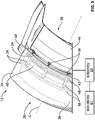
- FIG. 3 is a perspective view of part of VAFN 12 with movable structure 30 in the deployed position where porting flow passage 24 is open and slat 48 is sealingly engaged with radially-outer sealing element 42 and radially-inner sealing element 44 (not shown in FIG. 3 ).
- VAFN 12 may extend circumferentially at least partially around central axis C. In some embodiments, the circumferential span of VAFN 12 around central axis C may be substantially the same as that of thrust reverser 32 (see FIG. 1 ).
- the circumferential span of VAFN 12 around central axis C may be interrupted at a top location (e.g., around twelve o'clock) corresponding to a location of a pylon coupling engine 10 to an underside of an aircraft wing for example.
- VAFN 12 may comprise one or more discontinuous circumferential sections of VAFN 12 extending about central axis C.
- one or more porting flow passages 24 may be circumferentially disposed about central axis C. Porting flow passage(s) 24 may each define at least part of an annulus about central axis C.
- slat 48 may be fixedly attached to vane 46 via one or more brackets 50 extending across the space defining porting flow passage 24 between slat 48 and vane 46.
- Brackets 50 may be circumferentially spaced apart (distributed) about central axis C to provide the required structural support between slat 48 and vane 46.
- brackets 50 may have a generally streamlined shape to reduce resistance to the flow of bypass air being discharged via porting flow passage 24.
- components of VAFN 12 may be constructed using materials (e.g., fiber-reinforced composites, aluminum-based alloys) and manufacturing processes typically used in the production of nacelles and components thereof.
- FIG. 3 also schematically shows an exemplary actuation system including one more actuators 59 configured to cause movement (e.g., translation) of movable structure 30 and a suitable VAFN control system 61.
- FIG. 4 is an axial cross-section view of a radially-outer sealing element 42 of VAFN 12.
- Radially-outer sealing element 42 may extend circumferentially about central axis C and may have the same or similar circumferential span as slat 48 and as vane 46.
- radially-outer sealing element 42 may be a leaf-type seal.
- radially-outer sealing element 42 may be resiliently compressible and may be made from a suitable elastomeric material (e.g., silicon rubber).
- vane sealing portion 42A of radially-outer sealing element 42 for interfacing with (e.g., contacting) vane 46
- slat sealing portion 42B of radially-outer sealing element 42 for interfacing with (e.g., contacting) slat 48.
- vane sealing portion 42A and slat sealing portion 42B may be configured to be resiliently deformed (e.g., compressed) by the counterpart vane 46 and slat 48.
- radially-outer sealing element 42 may be configured so that radially-outer sealing element 42 is not permanently deformed from normal interfacing with vane 46 and slat 48.
- radially-outer sealing element 42 could be configured to be disposed in close enough proximity to the counterpart vane 46 and slat 48 to provide some (e.g., partial) sealing function without necessarily being resiliently deformed by or being in contact with vane 46 and/or slat 48 at the respective stowed and deployed positions of movable structure 30.
- FIG. 5 is an axial cross-section view of radially-inner sealing element 44 of VAFN 12.
- Radially-inner sealing element 44 may extend circumferentially about central axis C and may have the same or similar circumferential span as slat 48 and as vane 46.
- radially-inner sealing element 44 may be resiliently compressible and may be made from a suitable elastomeric material (e.g., silicon rubber).
- FIG. 5 shows vane sealing portion 44A of radially-inner sealing element 44 for interfacing with (e.g., contacting) vane 46, and slat sealing portion 44B of radially-inner sealing element 44 for interfacing with (e.g., contacting) slat 48.
- vane sealing portion 44A and slat sealing portion 44B may be configured to be resiliently deformed by the counterpart vane 46 and slat 48.
- radially-inner sealing element 44 may be configured so that radially-inner sealing element 44 is not permanently deformed from normal interfacing with vane 46 and slat 48.
- radially-inner sealing element 44 could be configured to be disposed in close enough proximity to the counterpart vane 46 and slat 48 to provide some substantial sealing capability without necessarily being resiliently deformed or being in contact with vane 46 and/or slat 48 at the respective stowed and deployed positions of movable structure 30.
- radially-inner sealing element 44 may comprise tongue 56 extending from main body 62.
- Vane sealing portion 44A and slat sealing portion 44B may comprise different (e.g., opposite) sides of tongue 56.
- Vane sealing portion 44A may be configured and located to contact a surface (e.g., forward-facing skin 54) of vane 46 facing porting flow passage 24.
- Slat sealing portion 44B may be configured and located to contact a surface (e.g., aft-facing side 58) of slat 48 facing porting flow passage 24.
- tongue 56 may be resiliently deflected in the aft direction when slat 48 is in the deployed position and engaged with tongue 56. Such resilient deflection can cause tongue 56 to be resiliently urged against aft-facing side 58 of slat 48 so that the seal provided by the contact interface between tongue 56 and slat 48 may withstand more negative pressure differential caused by relatively high-velocity airflow in porting flow passage 24.
- main body 62 of radially-inner sealing element 44 may be hollow and comprise one or more hollow cavities 64.
- a single cavity 64 in main body 62 may provide more stability in the stiffness of radially-inner sealing element 44 at different temperatures due to the lack of ribs or other structural elements of radially-inner sealing element 44 that could become stiffer at lower temperatures and affect the overall stiffness of radially-inner sealing element 44.
- radially-inner sealing element 44 may comprise one or more stiffeners 66 made from a material different from a material of main body 62 to achieve the desired behavior/properties of radially sealing element 44.
- stiffener 66 may be made from a metallic material.
Landscapes
- Engineering & Computer Science (AREA)
- Chemical & Material Sciences (AREA)
- Combustion & Propulsion (AREA)
- Mechanical Engineering (AREA)
- General Engineering & Computer Science (AREA)
- Structures Of Non-Positive Displacement Pumps (AREA)
Description
- The disclosure relates generally to a variable area fan nozzle for a turbofan aircraft engine.
- A turbofan aircraft engine typically includes an engine core, a nacelle that surrounds the engine core, and a fan that propels a flow of ambient air through the engine. The flow of ambient air is typically split into engine core airflow and bypass airflow through a bypass duct that surrounds the engine core and that is defined by the nacelle of the engine. The fan typically produces a majority of the thrust produced by the turbofan aircraft engine.
- When operating a turbofan aircraft engine, it can be desirable to vary the area of the outlet of the bypass duct (i.e., fan nozzle exit area) during different flight conditions. Varying the fan nozzle's exit area can adjust an engine's bypass flow characteristics (e.g., fan pressure ratio) to better match a particular flight condition or thrust level.
-
US2014030057 describes a variable area fan nozzle supported in a circumferential recess in the wall of the nacelle in front of it. An aft cascade is built into the nozzle, the openings of which are hidden within the recess when the nozzle is in the forward-most positions, and they are exposed to allow air to flow from the bypass duct through the cascade when the nozzle is in aft positions. -
US3779010 describes a thrust reversing and throat varying mechanism for a gas turbine engine. The effective nozzle flow area is varied by translating an intermediate cowling aft, to open up a passageway from the bypass duct. -
US2015308379 describes an integrated cascade and variable area fan nozzle. A "VAFN" panel is deployable aft to open a port that communicates with the bypass exhaust. - The invention is in accordance with the variable area fan nozzle for a turbofan aircraft engine of
claim 1. The variable area fan nozzle comprises: - a first structure defining a forward portion of a bypass duct of the turbofan aircraft engine; and
- a second structure defining an aft portion of the bypass duct disposed aft of the forward portion of the bypass duct, the second structure being movable relative to the first structure between a deployed position where a porting flow passage defined between the forward portion of the bypass duct and the aft portion of the bypass duct is open, and a stowed position where the porting flow passage is closed, the second structure comprising:
- a vane; and
- a slat attached to the vane and disposed forward of the vane, the porting flow passage extending between the slat and the vane when the second structure is in the deployed position.
- The slat may be received in a cavity inside the first structure when the second structure is in the stowed position.
- The vane may comprise a forward aerodynamic surface and the slat may comprise an aft aerodynamic surface spaced apart from the forward aerodynamic surface of the vane. The forward aerodynamic surface of the vane and the aft aerodynamic surface of the slat may at least partially define the porting flow passage.
- The forward aerodynamic surface of the vane and the aft aerodynamic surface of the slat may both be convex relative to the porting flow passage.
- The slat may be attached to the vane via one or more brackets extending across the porting flow passage.
- The slat may be sealed with the first structure when the second structure is in the deployed position. The vane may be sealed with the first structure when the second structure is in the stowed position.
- The variable area fan nozzle may comprise a radially-outer sealing element configured and disposed to provide a radially-outer sealed interface between the first structure and the second structure.
- The radially-outer sealing element may be attached to the first structure and may comprise:
- a radially-outer vane sealing portion for interfacing with the vane when the second structure is in the stowed position; and
- a radially-outer slat sealing portion for interfacing with the slat when the second structure is in the deployed position.
- The radially-outer sealing element may be sealingly engaged with a radially-outer skin of the vane when the second structure is in the stowed position.
- The first sealing element may be a leaf-type seal.
- The slat may comprise an aft aerodynamic surface spaced apart from the vane. The aft aerodynamic surface of the slat may at least partially define the porting flow passage. The slat may comprise a portion other than the aft aerodynamic surface of the slat for interfacing with a radially-outer sealing element attached to the first structure.
- The portion other than the aft aerodynamic surface of the slat may be defined by a protrusion disposed on a side of the slat opposite the aft aerodynamic surface of the slat.
- The variable area fan nozzle according to the invention comprises a radially-inner sealing element configured and disposed to provide a radially-inner sealed interface between an inner skin (36) of the first structure (28) defining part of forward portion (16A) and a forward-facing skin (54) of the vane (46) of the second structure.
- The radially-inner sealing element is attached to the first structure and may comprise:
- a radially-inner vane sealing portion for interfacing with the vane when the second structure is in the stowed position; and
- a radially-inner slat sealing portion for interfacing with the slat when the second structure is in the deployed position.
- The radially-inner sealing element is configured to provide a sealed interface between the forward and aft portions of the bypass duct when the second structure is in the stowed position.
- The radially-inner sealing element may comprise a tongue extending from a main body. The radially-inner vane sealing portion and the radially-inner slat sealing portion may comprise different sides of the tongue.
- The tongue may be configured and located to contact a surface of the slat facing the porting flow passage.
- The main body of the radially-inner sealing element may be hollow.
- The radially-inner sealing element may comprise a stiffener made from a material different from a material of the main body.
- The vane of the second structure may at least partially define a non-porting flow exit. Movement of the second structure from the stowed position to the deployed position causes an increase in an exit plane area of the non-porting flow exit.
- The variable area fan nozzle may comprise
- a radially-outer sealing element configured and disposed to provide a radially-outer sealed interface between the first structure and the second structure; and
- comprises a radially-inner sealing element configured and disposed to provide a radially-inner sealed interface between the first structure and the second structure.
- Also disclosed is a nacelle for a turbofan aircraft engine, the nacelle comprising the variable area fan nozzle as described herein.
- Also disclosed herein is an aircraft engine comprising the variable area fan nozzle as described herein.
- Further details of the subject matter of this application will be apparent from the detailed description included below and the drawings.
- Reference is now made to the accompanying drawings, in which:
-
FIG. 1 shows an upper half of an axial cross-section view of a turbofan aircraft engine comprising an exemplary variable area fan nozzle (VAFN) as described herein; -
FIG. 2A is an axial cross-section view of the VAFN of the engine ofFIG. 1 in the stowed position; -
FIG. 2B is an axial cross-section view of the VAFN of the engine ofFIG. 1 in the deployed position; -
FIG. 3 is a perspective view of part of the VAFN in the deployed position; -
FIG. 4 is an axial cross-section view of a radially-outer sealing element of the VAFN; and -
FIG. 5 is an axial cross-section view of a radially-inner sealing element of the VAFN. - The following disclosure relates to turbofan aircraft engines including variable area fan nozzles (VAFNs). In various embodiments, a VAFN as described herein includes a forward structure defining a forward portion of a bypass duct of the turbofan aircraft engine and a movable aft structure defining an aft portion of the bypass duct. The movable structure may be movable (e.g., translatable) relative to the forward structure between a deployed position where a porting flow passage defined between the forward portion of the bypass duct and the aft portion of the bypass duct is open, and a stowed position where the porting flow passage is closed. The porting flow passage may provide an additional channel for bypass air flowing in the bypass duct to be vented overboard. In some embodiments, the sealing between the forward structure and the movable structure may be provided by way of a radially-outer seal and a separate radially-inner seal.
- Aspects of various embodiments are described through reference to the drawings.
-
FIG. 1 shows an upper half of an axial cross-section view ofturbofan aircraft engine 10 comprising an exemplary variable area fan nozzle 12 (referred hereinafter as "VAFN 12").Engine 10 may be of a type for use in aircraft applications. For example,engine 10 may comprise a turbofan type of engine for propelling a suitable aircraft such as corporate, private, commercial or a narrow-body, twin engine jet airliner for example.Engine 10 may comprisefan 14 through which ambient air is propelled,bypass duct 16 andcore section 18.Core section 18 may comprise, in serial flow, a compressor section, a combustor and a turbine section.Bypass duct 16 may be defined by and extend betweennacelle 20 andcasing 22 ofengine 10.Engine 10 may have a central axis C which may also correspond to an axis of rotation offan 14.Bypass duct 16 may be generally circumferentially uniform about central axis C. For example, bypassduct 16 may extend at least partially around central axis C ofengine 10. In various embodiments,engine 10 may have a relatively high bypass ratio. -
VAFN 12 may serve to vary the size of the exit area available to the bypass airflow inbypass duct 16 during various flight/operating conditions ofengine 10. In some flight/operating conditions, it might be desirable to have a larger exit area available for the bypass airflow to exitbypass duct 16 and in other flight/operating conditions, it might be desirable to have a smaller exit area available for the bypass airflow to exitbypass duct 16.VAFN 12 may be configured to vary the exit area by opening or closingporting flow passage 24 and also by varying the exit plane area ofnon-porting flow exit 26. -
Engine 10 may have generally forward and aft directions as indicated inFIG. 1 . The forward direction may be the typical direction of movement ofengine 10 when used to propel an aircraft in flight.VAFN 12 may compriseforward structure 28 defining forwardportion 16A ofbypass duct 16 ofengine 10 andmovable structure 30 definingaft portion 16B ofbypass duct 16 disposed aft offorward portion 16A ofbypass duct 16.Movable structure 30 may be translatable generally along central axis C relative to forwardstructure 28 between a deployed position where portingflow passage 24 defined betweenforward portion 16A ofbypass duct 16 andaft portion 16B ofbypass duct 16 is open, and, a stowed position where portingflow passage 24 is closed.FIG. 1 showsmovable structure 30 in the deployed position where portingflow passage 24 is open. - The translation of
movable structure 30 may also cause a change in the exit plane area ofnon-porting flow exit 26. Dimensions A1 and A2 illustrated inFIG. 1 can be indicative of the change in exit plane area ofnon-porting flow exit 26. Dimension A1 represents a shorter radial distance between a trailing edge ofmovable structure 30 andcasing 22 whenmovable structure 30 is in the stowed position. On the other hand, dimension A2 represents a longer radial distance between the trailing edge ofmovable structure 30 andcasing 22 whenmovable structure 30 is in the deployed position. The translation ofmovable structure 30 in the aft direction and generally along central axis C, in combination with the radially-inwardly sloping outer surface of casing 22 (i.e., relative geometry change) may cause the illustrated increase in exit plane area ofnon-porting exit 26. The use of portingflow passage 24 in addition to varying the exit plane area ofnon-porting flow exit 26 may promote shorter translation ofmovable structure 30 being required compared to relying only on the increase in exit plane area ofnon-porting exit 26 to achieve a desired increase in exit area. The shorter travel distance may hence facilitate the use of a shorter and lighter actuation system. In some installations,engine 10 may comprise asuitable thrust reverser 32, of whichforward structure 28 ofnacelle 20 may be part. -
Porting flow passage 24 may provide a porting (e.g., bypass, alternate) flow exit where bypass airflow inside ofbypass duct 16 may be discharged frombypass duct 16.Movable structure 30 may be movable between a stowed (i.e., forward) position where portingflow passage 24 is closed and a deployed (i.e., aft) position where portingflow passage 24 is fully open. It is understood that, in some embodiments,VAFN 12 may be configured so thatmovable structure 30 may be moved to and held at an intermediate position between the fully stowed position and the fully deployed position to achieve a different intermediate size of portingflow passage 24 and also achieve a different intermediate size of the exit plane area ofnon-porting exit 26. It is understood that any suitable actuation mechanism (seeFIG. 3 ) may be used to actuatemovable structure 30 between the stowed and deployed positions relative toforward structure 28. -
FIG. 2A is an enlarged axial cross-section view ofVAFN 12 ofengine 10 showingmovable structure 30 in the stowed position where portingflow passage 24 is closed. In some embodiments,forward structure 28 may comprise or be part of a translatable cowl (transcowl) that is part ofthrust reverser 32. Even thoughforward structure 28 is referenced herein as being fixed or stationary in the context of the operation ofVAFN 12, it is understood that forward structure 28 (e.g., transcowl) could also be movable in another context such as in the operation ofthrust reverser 32. - Stowing/retraction of
movable structure 30 may include translation ofmovable structure 30 generally in the forward direction relative toforward structure 28.Forward structure 28 ofnacelle 20 may includeouter skin 34 for interfacing with a flow of ambient air outside ofengine 10, andinner skin 36 defining part offorward portion 16A ofbypass duct 16 for interfacing with bypass airflow.Forward structure 28 may comprise structural members 38 (e.g., braces, ribs) supportingouter skin 34 andinner skin 36.Forward structure 28 may definecavity 40 into which a portion ofmovable structure 30 is received whenmovable structure 30 is in the stowed position.Forward structure 28 may comprise radially-outer sealing element 42 configured and disposed to provide a radially-outer sealed interface betweenforward structure 28 andmovable structure 30.Forward structure 28 may also comprise radially-inner sealing element 44 configured and disposed to provide a radially-inner sealed interface betweenforward structure 28 andmovable structure 30. -
Movable structure 30 may comprisevane 46 andslat 48.Slat 48 may be attached tovane 46 and disposed forward ofvane 46.Slat 48 may be attached to vane 46 via one ormore brackets 50 extending betweenvane 46 andslat 48. In the configuration shown inFIG. 2A ,slat 48 and bracket(s) 50 can be received insidecavity 40 offorward structure 28 whenmovable structure 30 is in the stowed position where porting passage 24 (seeFIG. 1 ) is closed. - Radially-
outer sealing element 42 may be configured and disposed to provide a radially-outer sealed interface betweenforward structure 28 andmovable structure 30 in both the stowed and deployed positions ofmovable structure 30. In some embodiments, radially-outer sealing element 42 may be fixedly secured to forwardstructure 28 by suitable means and may sealingly engage with a radially-outer skin 52 ofvane 46 whenmovable structure 30 is in the stowed position. In other words, radially-outer sealing element 42 may provide a substantially sealed interface betweenouter skin 34 offorward structure 28 andouter skin 52 ofvane 46 whenmovable structure 30 is in the stowed position. Radially-outer sealing element 42 may comprisevane sealing portion 42A (seeFIG. 4 ) for interfacing withvane 46 whenmovable structure 30 is in the stowed position. - Radially-
inner sealing element 44 may be configured and disposed to provide a radially-inner sealed interface betweenforward structure 28 andmovable structure 30 in both the stowed and deployed positions ofmovable structure 30. In some embodiments, radially-inner sealing element 44 may be fixedly secured to forwardstructure 28 by suitable means and may sealingly engage with a forward-facingskin 54 ofvane 46 facing forwardstructure 28, whenmovable structure 30 is in the stowed position. In other words, radially-inner sealing element 44 may provide a substantially sealed interface betweeninner skin 36 offorward structure 28 andvane 46 whenmovable structure 30 is in the stowed position. For example, radially-inner sealing element 44 may provide a substantially sealed interface betweenforward portion 16A andaft portion 16B ofbypass duct 16 whenmovable structure 30 is in the stowed position. Radially-inner sealing element 44 may comprisevane sealing portion 44A (seeFIG. 5 ) for interfacing withvane 46 whenmovable structure 30 is in the stowed position. In some embodiments,vane sealing portion 44A of radially-inner sealing element 44 may comprise a first side oftongue 56 that is facingvane 46. -
FIG. 2B is an enlarged axial cross-section view ofVAFN 12 ofengine 10 showingmovable structure 30 in the deployed position where portingflow passage 24 is open.Porting flow passage 24 may be disposed axially betweenforward portion 16A andaft portion 16B ofbypass duct 16. Deployment ofmovable structure 30 may include translation ofmovable structure 30 generally in the aft direction relative toforward structure 28. In this configuration, bypass airflow inbypass duct 16 can exitbypass duct 16 via both portingflow passage 24 and non-porting flow exit 26 (seeFIG. 1 ) so that the overall exit cross-sectional area out ofbypass duct 16 available to the bypass airflow is increased whenmovable structure 30 is in the deployed position compared to whenmovable structure 30 is in the stowed position. - The aft movement of
movable structure 30 during deployment may causevane 46 to become unsealed from sealingelements flow passage 24 betweenforward structure 28 andvane 46 may then be formed. The deployment ofmovable structure 30 may also cause bracket(s) 50 andslat 48 to at least partially retract fromcavity 40 untilslat 48 becomes in sealing engagement with sealingelements FIG. 2B showsmovable structure 30 in the fully deployed position where portingflow passage 24 is fully open.Porting flow passage 24 may extend through a space betweenslat 48 andvane 46 ofmovable structure 30. For example, forward-facingskin 54 ofvane 46 may comprise an aerodynamic surface defining at least a portion of an aft side of portingflow passage 24. Similarly,slat 48 may comprise aft-facingside 58 comprising an aerodynamic surface defining at least a portion of a forward side of portingflow passage 24. Forward-facingskin 54 and aft-facingside 58 ofslat 48 may be spaced apart from each other and at least partially define portingflow passage 24 therebetween. In some embodiments, the aerodynamic surface defined by aft-facingside 58 ofslat 48 may be convex relative to portingflow passage 24 so as to be curved or rounded toward/into portingflow passage 24. In some embodiments, the aerodynamic surface defined by forward-facingskin 54 ofvane 46 may similarly be convex relative to portingflow passage 24 so as to be curved or rounded toward/into portingflow passage 24. - Radially-
outer sealing element 42 may be configured and disposed to provide a radially-outer sealed interface betweenouter skin 34 offorward structure 28 andslat 48 ofmovable structure 30 whenmovable structure 30 is in the deployed position. Radially-outer sealing element 42 may compriseslat sealing portion 42B for interfacing withslat 48 whenmovable structure 30 is in the deployed position.Slat sealing portion 42B of radially-outer sealing element 42 may be configured to sealingly engage a portion ofmovable structure 30 other than the aerodynamic surface defined by aft-facingside 58 ofslat 48. For example, in some embodiments,slat sealing portion 42B may be configured to sealingly engage a protrusion 60 (e.g., ridge) disposed on a forward side ofslat 48 opposite aft-facingside 58 ofslat 48. - Radially-
inner sealing element 44 may be configured and disposed to provide a radially-inner sealed interface betweeninner skin 36 offorward structure 28 andslat 48 ofmovable structure 30 whenmovable structure 30 is in the deployed position. Radially-inner sealing element 44 may compriseslat sealing portion 44B for interfacing withslat 48 whenmovable structure 30 is in the deployed position. Radially-inner sealing element 44 may provide a substantially sealed interface betweeninner skin 36 offorward structure 28 andslat 48 whenmovable structure 30 is in the deployed position. In some embodiments,vane sealing portion 44A (seeFIG. 2A ) of radially-inner sealing element 44 may comprise a second side oftongue 56 opposite to portingflow passage 24. In some embodiments,tongue 56 may be resiliently biased away from portingflow passage 24 so that the engagement ofslat 48 withtongue 56 of radially-inner sealing element 44 during deployment ofmovable structure 30 may cause resilient deflection oftongue 56 and thereby cause urging oftongue 56 towardslat 48 and enhance the performance of the sealing interface betweentongue 56 andslat 48 in some situations. -
FIG. 3 is a perspective view of part ofVAFN 12 withmovable structure 30 in the deployed position where portingflow passage 24 is open andslat 48 is sealingly engaged with radially-outer sealing element 42 and radially-inner sealing element 44 (not shown inFIG. 3 ). It is understood thatVAFN 12 may extend circumferentially at least partially around central axis C. In some embodiments, the circumferential span of VAFN 12 around central axis C may be substantially the same as that of thrust reverser 32 (seeFIG. 1 ). In some embodiments, the circumferential span of VAFN 12 around central axis C may be interrupted at a top location (e.g., around twelve o'clock) corresponding to a location of apylon coupling engine 10 to an underside of an aircraft wing for example. In some embodiments,VAFN 12 may comprise one or more discontinuous circumferential sections ofVAFN 12 extending about central axis C. Accordingly, one or moreporting flow passages 24 may be circumferentially disposed about central axis C. Porting flow passage(s) 24 may each define at least part of an annulus about central axis C. - As explained above,
slat 48 may be fixedly attached to vane 46 via one ormore brackets 50 extending across the space definingporting flow passage 24 betweenslat 48 andvane 46.Brackets 50 may be circumferentially spaced apart (distributed) about central axis C to provide the required structural support betweenslat 48 andvane 46. In some embodiments,brackets 50 may have a generally streamlined shape to reduce resistance to the flow of bypass air being discharged via portingflow passage 24. It is understood that components ofVAFN 12 may be constructed using materials (e.g., fiber-reinforced composites, aluminum-based alloys) and manufacturing processes typically used in the production of nacelles and components thereof.FIG. 3 also schematically shows an exemplary actuation system including onemore actuators 59 configured to cause movement (e.g., translation) ofmovable structure 30 and a suitableVAFN control system 61. -
FIG. 4 is an axial cross-section view of a radially-outer sealing element 42 ofVAFN 12. Radially-outer sealing element 42 may extend circumferentially about central axis C and may have the same or similar circumferential span asslat 48 and asvane 46. In some embodiments, radially-outer sealing element 42 may be a leaf-type seal. In some embodiments, radially-outer sealing element 42 may be resiliently compressible and may be made from a suitable elastomeric material (e.g., silicon rubber).FIG. 4 showsvane sealing portion 42A of radially-outer sealing element 42 for interfacing with (e.g., contacting)vane 46, andslat sealing portion 42B of radially-outer sealing element 42 for interfacing with (e.g., contacting)slat 48. In some embodiments,vane sealing portion 42A andslat sealing portion 42B may be configured to be resiliently deformed (e.g., compressed) by thecounterpart vane 46 andslat 48. However, it is understood that radially-outer sealing element 42 may be configured so that radially-outer sealing element 42 is not permanently deformed from normal interfacing withvane 46 andslat 48. - Alternatively, it is understood that radially-
outer sealing element 42 could be configured to be disposed in close enough proximity to thecounterpart vane 46 andslat 48 to provide some (e.g., partial) sealing function without necessarily being resiliently deformed by or being in contact withvane 46 and/orslat 48 at the respective stowed and deployed positions ofmovable structure 30. -
FIG. 5 is an axial cross-section view of radially-inner sealing element 44 ofVAFN 12. Radially-inner sealing element 44 may extend circumferentially about central axis C and may have the same or similar circumferential span asslat 48 and asvane 46. In some embodiments, radially-inner sealing element 44 may be resiliently compressible and may be made from a suitable elastomeric material (e.g., silicon rubber).FIG. 5 showsvane sealing portion 44A of radially-inner sealing element 44 for interfacing with (e.g., contacting)vane 46, andslat sealing portion 44B of radially-inner sealing element 44 for interfacing with (e.g., contacting)slat 48. In some embodiments,vane sealing portion 44A andslat sealing portion 44B may be configured to be resiliently deformed by thecounterpart vane 46 andslat 48. However, it is understood that radially-inner sealing element 44 may be configured so that radially-inner sealing element 44 is not permanently deformed from normal interfacing withvane 46 andslat 48. - Alternatively, it is understood that radially-
inner sealing element 44 could be configured to be disposed in close enough proximity to thecounterpart vane 46 andslat 48 to provide some substantial sealing capability without necessarily being resiliently deformed or being in contact withvane 46 and/orslat 48 at the respective stowed and deployed positions ofmovable structure 30. - As explained above, radially-
inner sealing element 44 may comprisetongue 56 extending frommain body 62.Vane sealing portion 44A andslat sealing portion 44B may comprise different (e.g., opposite) sides oftongue 56.Vane sealing portion 44A may be configured and located to contact a surface (e.g., forward-facing skin 54) ofvane 46 facing portingflow passage 24.Slat sealing portion 44B may be configured and located to contact a surface (e.g., aft-facing side 58) ofslat 48 facing portingflow passage 24. - In some embodiments,
tongue 56 may be resiliently deflected in the aft direction when slat 48 is in the deployed position and engaged withtongue 56. Such resilient deflection can causetongue 56 to be resiliently urged against aft-facingside 58 ofslat 48 so that the seal provided by the contact interface betweentongue 56 andslat 48 may withstand more negative pressure differential caused by relatively high-velocity airflow in portingflow passage 24. - In light of the present disclosure, it is understood that the shape, material and configuration of radially-
inner sealing element 44 and of radially-outer sealing element 42 may be different than the exemplary embodiments shown herein to provide the desired stiffness and sealing performance. For example, in some embodiments,main body 62 of radially-inner sealing element 44 may be hollow and comprise one or morehollow cavities 64. In some embodiments asingle cavity 64 inmain body 62 may provide more stability in the stiffness of radially-inner sealing element 44 at different temperatures due to the lack of ribs or other structural elements of radially-inner sealing element 44 that could become stiffer at lower temperatures and affect the overall stiffness of radially-inner sealing element 44. In some embodiments radially-inner sealing element 44 may comprise one ormore stiffeners 66 made from a material different from a material ofmain body 62 to achieve the desired behavior/properties of radially sealingelement 44. In some embodiments,stiffener 66 may be made from a metallic material.
Claims (14)
- A variable area fan nozzle (12) for a turbofan aircraft engine (10), the variable area fan nozzle (12) comprising:a first structure (28) defining a forward portion (16A) of a bypass duct (16) of the turbofan aircraft engine; anda second structure (30) defining an aft portion (16B) of the bypass duct disposed aft of the forward portion of the bypass duct, the second structure being movable relative to the first structure between a deployed position where a porting flow passage (24) defined between the forward portion of the bypass duct and the aft portion of the bypass duct is open, and a stowed position where the porting flow passage is closed, the second structure comprising:a vane (46); anda slat (48) attached to the vane and disposed forward of the vane, the porting flow passage extending between the slat and the vane when the secondstructure is in the deployed position;the variable area fan nozzle further comprising a radially-inner sealing element (44) fixedly secured to the first structure and configured and disposed to provide a radially-inner sealed interface between an inner skin (36) of the first structure (28) defining part of forward portion (16A) and a forward-facing skin (54) of the vane (46) of the second structure (30), when the second structure is in the stowed position;the vane at least partially defining a non-porting flow exit (26); and wherein movement of the second structure from the stowed position to the deployed position causes an increase in an exit plane area of the non-porting flow exit.
- The variable area fan nozzle (12) as defined in claim 1, wherein the slat (48) is received in a cavity (40) inside the first structure (28) when the second structure (30) is in the stowed position.
- The variable area fan nozzle (12) as defined in claim 1 or claim 2, wherein the vane (46) comprises a forward aerodynamic surface (54) and the slat comprises an aft aerodynamic surface (58) spaced apart from the forward aerodynamic surface of the vane, the forward aerodynamic surface of the vane and the aft aerodynamic surface of the slat at least partially defining the porting flow passage (24).
- The variable area fan nozzle (12) as defined in claim 3, wherein the forward aerodynamic surface (54) of the vane and the aft aerodynamic surface (58) of the slat (48) are both convex relative to the porting flow passage (24).
- The variable area fan nozzle (12) as defined in any one of claims 1 to 4, wherein the slat (48) is attached to the vane (46) via one or more brackets (50) extending across the porting flow passage (24).
- The variable area fan nozzle (12) as defined in any one of claims 1 to 5, wherein:the slat (48) is sealed with the first structure (28) when the second structure (30) is in the deployed position; andthe vane is sealed with the first structure when the second structure is in the stowed position.
- The variable area fan nozzle (12) as defined in any one of claims 1 to 6, comprising a radially-outer sealing element (42) configured and disposed to provide a radially-outer sealed interface between the first structure (28) and the second structure (30).
- The variable area fan nozzle (12) as defined in claim 7, wherein the radially-outer sealing element (42) is attached to the first structure (28) and comprises:a radially-outer vane sealing portion (42A) for interfacing with the vane (46) when the second structure (30) is in the stowed position; anda radially-outer slat sealing portion (42B) for interfacing with the slat (48) when the second structure is in the deployed position.
- The variable area fan nozzle (12) as defined in claim 8, wherein the radially-outer sealing element (42) is sealingly engaged with a radially-outer skin (52) of the vane (48) when the second structure (30) is in the stowed position.
- The variable area fan nozzle (12) as defined in any one of claims 7 to 9, wherein the radially-outer sealing element (42) is a leaf-type seal.
- The variable area fan nozzle (12) as defined in claim 1 or claim 2, wherein:
the slat comprises an aft aerodynamic surface spaced apart from the vane;
the aft aerodynamic surface of the slat at least partially defines the porting flow passage; and the slat comprises a portion (60) other than the aft aerodynamic surface of the slat for interfacing with a radially-outer sealing element (42) attached to the first structure. - The variable area fan nozzle (12) as defined in claim 11, wherein the portion (60) other than the aft aerodynamic surface (58) of the slat (48) is defined by a protrusion (60) disposed on a side of the slat opposite the aft aerodynamic surface of the slat.
- The variable area fan nozzle (12) as defined in claim 1, wherein the radially-inner sealing element (44) is attached to the first structure (28) and comprises:a radially-inner vane sealing portion (44A) for interfacing with the vane (46) when the second structure (30) is in the stowed position; anda radially-inner slat sealing portion (44B) for interfacing with the slat (48) when the second structure is in the deployed position.
- The variable area fan nozzle as defined in claim 13, wherein the radially-inner sealing element (44) is configured to provide a sealed interface between the forward and aft portions (16A, 16B) of the bypass duct (16) when the second structure (30) is in the stowed position.
Applications Claiming Priority (2)
| Application Number | Priority Date | Filing Date | Title |
|---|---|---|---|
| GBGB1720950.3A GB201720950D0 (en) | 2017-12-15 | 2017-12-15 | Variable area fan nozzle for turbofan aircraft engine |
| PCT/GB2018/053545 WO2019116008A1 (en) | 2017-12-15 | 2018-12-06 | Variable area fan nozzle for turbofan aircraft engine |
Publications (2)
| Publication Number | Publication Date |
|---|---|
| EP3724480A1 EP3724480A1 (en) | 2020-10-21 |
| EP3724480B1 true EP3724480B1 (en) | 2022-06-22 |
Family
ID=61008878
Family Applications (1)
| Application Number | Title | Priority Date | Filing Date |
|---|---|---|---|
| EP18822443.0A Not-in-force EP3724480B1 (en) | 2017-12-15 | 2018-12-06 | Variable area fan nozzle for turbofan aircraft engine |
Country Status (6)
| Country | Link |
|---|---|
| US (1) | US11408370B2 (en) |
| EP (1) | EP3724480B1 (en) |
| CN (1) | CN111479997A (en) |
| CA (1) | CA3085679A1 (en) |
| GB (1) | GB201720950D0 (en) |
| WO (1) | WO2019116008A1 (en) |
Families Citing this family (2)
| Publication number | Priority date | Publication date | Assignee | Title |
|---|---|---|---|---|
| US11802523B2 (en) * | 2020-12-12 | 2023-10-31 | Rohr, Inc. | Multi-lobed bullnose ramp |
| US20240401546A1 (en) * | 2023-06-01 | 2024-12-05 | General Electric Company | Turbine engine having a thrust reverser system |
Family Cites Families (14)
| Publication number | Priority date | Publication date | Assignee | Title |
|---|---|---|---|---|
| GB1386232A (en) * | 1971-03-31 | 1975-03-05 | Short Brothers & Harland Ltd | Fluid propulsion systems |
| US3779010A (en) * | 1972-08-17 | 1973-12-18 | Gen Electric | Combined thrust reversing and throat varying mechanism for a gas turbine engine |
| FR2622929A1 (en) * | 1987-11-05 | 1989-05-12 | Hispano Suiza Sa | DRIVE INVERTER OF GRID TURBOREACTOR, WITH VARIABLE EJECTION SECTION |
| US5778659A (en) * | 1994-10-20 | 1998-07-14 | United Technologies Corporation | Variable area fan exhaust nozzle having mechanically separate sleeve and thrust reverser actuation systems |
| EP2479414B1 (en) | 2007-08-08 | 2015-06-10 | Rohr, Inc. | Variable area fan nozzle with bypass flow |
| GB201112986D0 (en) * | 2011-07-28 | 2011-09-14 | Rolls Royce Plc | Ducted fan gas turbine assembly |
| US9103298B2 (en) * | 2011-12-29 | 2015-08-11 | Rohr, Inc. | Seal for a variable area fan nozzle |
| US9617871B2 (en) * | 2012-07-24 | 2017-04-11 | Rohr, Inc. | AFT cascade translating variable area fan nozzle |
| FR2995876B1 (en) * | 2012-07-24 | 2019-05-03 | Rohr, Inc | INTEGRATED VARIABLE SECTION BLOWER ASSEMBLY WITH INTEGRATED PUSH INVERTER |
| US10077739B2 (en) * | 2014-04-24 | 2018-09-18 | Rohr, Inc. | Dual actuation system for cascade and thrust reverser panel for an integral cascade variable area fan nozzle |
| DE102015203219A1 (en) * | 2015-02-23 | 2016-08-25 | Rolls-Royce Deutschland Ltd & Co Kg | Engine cowling of a gas turbine with thrust reverser and adjustable in cross-section exhaust nozzle |
| US10514004B2 (en) * | 2015-12-14 | 2019-12-24 | Rohr, Inc. | Cascade assembly for a thrust reverser of an aircraft nacelle |
| US10428764B2 (en) * | 2016-02-10 | 2019-10-01 | Rohr, Inc. | Deflection limiter for a cascade assembly of a thrust reverser |
| US10605198B2 (en) * | 2016-04-15 | 2020-03-31 | Rohr, Inc. | Nacelle thrust reverser |
-
2017
- 2017-12-15 GB GBGB1720950.3A patent/GB201720950D0/en not_active Ceased
-
2018
- 2018-12-06 WO PCT/GB2018/053545 patent/WO2019116008A1/en not_active Ceased
- 2018-12-06 CN CN201880080821.7A patent/CN111479997A/en active Pending
- 2018-12-06 EP EP18822443.0A patent/EP3724480B1/en not_active Not-in-force
- 2018-12-06 US US16/772,480 patent/US11408370B2/en active Active
- 2018-12-06 CA CA3085679A patent/CA3085679A1/en active Pending
Also Published As
| Publication number | Publication date |
|---|---|
| US11408370B2 (en) | 2022-08-09 |
| EP3724480A1 (en) | 2020-10-21 |
| CA3085679A1 (en) | 2019-06-20 |
| US20200400096A1 (en) | 2020-12-24 |
| CN111479997A (en) | 2020-07-31 |
| GB201720950D0 (en) | 2018-01-31 |
| WO2019116008A1 (en) | 2019-06-20 |
Similar Documents
| Publication | Publication Date | Title |
|---|---|---|
| EP3244051B1 (en) | Gas turbine engine with thrust reverser assembly and method of operating | |
| US8104262B2 (en) | Dual function cascade integrated variable area fan nozzle and thrust reverser | |
| US9103298B2 (en) | Seal for a variable area fan nozzle | |
| EP1595067B1 (en) | Recessed engine nacelle | |
| US8052085B2 (en) | Thrust reverser for a turbofan gas turbine engine | |
| US20040079073A1 (en) | Cascadeless fan thrust reverser with plume control | |
| US10184426B2 (en) | Thrust reverser with forward positioned blocker doors | |
| US20160230702A1 (en) | Extended thrust reverser cascade | |
| EP3347587B1 (en) | Thrust reverser assembly | |
| EP3256710B1 (en) | Turbine engine with variable area nozzle | |
| EP4242444B1 (en) | Thrust reverser for variable area nozzle | |
| US10001080B2 (en) | Thrust reverse variable area fan nozzle | |
| EP3724480B1 (en) | Variable area fan nozzle for turbofan aircraft engine | |
| EP3441601B1 (en) | Turbine engine thrust reverser stop | |
| US9856742B2 (en) | Sealing system for variable area fan nozzle | |
| EP4191047B1 (en) | Variable area nozzle and method for operating same |
Legal Events
| Date | Code | Title | Description |
|---|---|---|---|
| STAA | Information on the status of an ep patent application or granted ep patent |
Free format text: STATUS: UNKNOWN |
|
| STAA | Information on the status of an ep patent application or granted ep patent |
Free format text: STATUS: THE INTERNATIONAL PUBLICATION HAS BEEN MADE |
|
| PUAI | Public reference made under article 153(3) epc to a published international application that has entered the european phase |
Free format text: ORIGINAL CODE: 0009012 |
|
| STAA | Information on the status of an ep patent application or granted ep patent |
Free format text: STATUS: REQUEST FOR EXAMINATION WAS MADE |
|
| 17P | Request for examination filed |
Effective date: 20200714 |
|
| AK | Designated contracting states |
Kind code of ref document: A1 Designated state(s): AL AT BE BG CH CY CZ DE DK EE ES FI FR GB GR HR HU IE IS IT LI LT LU LV MC MK MT NL NO PL PT RO RS SE SI SK SM TR |
|
| AX | Request for extension of the european patent |
Extension state: BA ME |
|
| DAV | Request for validation of the european patent (deleted) | ||
| DAX | Request for extension of the european patent (deleted) | ||
| STAA | Information on the status of an ep patent application or granted ep patent |
Free format text: STATUS: EXAMINATION IS IN PROGRESS |
|
| 17Q | First examination report despatched |
Effective date: 20210429 |
|
| GRAP | Despatch of communication of intention to grant a patent |
Free format text: ORIGINAL CODE: EPIDOSNIGR1 |
|
| STAA | Information on the status of an ep patent application or granted ep patent |
Free format text: STATUS: GRANT OF PATENT IS INTENDED |
|
| INTG | Intention to grant announced |
Effective date: 20220330 |
|
| GRAS | Grant fee paid |
Free format text: ORIGINAL CODE: EPIDOSNIGR3 |
|
| GRAA | (expected) grant |
Free format text: ORIGINAL CODE: 0009210 |
|
| STAA | Information on the status of an ep patent application or granted ep patent |
Free format text: STATUS: THE PATENT HAS BEEN GRANTED |
|
| AK | Designated contracting states |
Kind code of ref document: B1 Designated state(s): AL AT BE BG CH CY CZ DE DK EE ES FI FR GB GR HR HU IE IS IT LI LT LU LV MC MK MT NL NO PL PT RO RS SE SI SK SM TR |
|
| REG | Reference to a national code |
Ref country code: GB Ref legal event code: FG4D |
|
| REG | Reference to a national code |
Ref country code: CH Ref legal event code: EP |
|
| REG | Reference to a national code |
Ref country code: DE Ref legal event code: R096 Ref document number: 602018037110 Country of ref document: DE |
|
| REG | Reference to a national code |
Ref country code: AT Ref legal event code: REF Ref document number: 1499912 Country of ref document: AT Kind code of ref document: T Effective date: 20220715 |
|
| REG | Reference to a national code |
Ref country code: IE Ref legal event code: FG4D |
|
| REG | Reference to a national code |
Ref country code: LT Ref legal event code: MG9D |
|
| REG | Reference to a national code |
Ref country code: NL Ref legal event code: MP Effective date: 20220622 |
|
| PG25 | Lapsed in a contracting state [announced via postgrant information from national office to epo] |
Ref country code: SE Free format text: LAPSE BECAUSE OF FAILURE TO SUBMIT A TRANSLATION OF THE DESCRIPTION OR TO PAY THE FEE WITHIN THE PRESCRIBED TIME-LIMIT Effective date: 20220622 Ref country code: NO Free format text: LAPSE BECAUSE OF FAILURE TO SUBMIT A TRANSLATION OF THE DESCRIPTION OR TO PAY THE FEE WITHIN THE PRESCRIBED TIME-LIMIT Effective date: 20220922 Ref country code: LT Free format text: LAPSE BECAUSE OF FAILURE TO SUBMIT A TRANSLATION OF THE DESCRIPTION OR TO PAY THE FEE WITHIN THE PRESCRIBED TIME-LIMIT Effective date: 20220622 Ref country code: HR Free format text: LAPSE BECAUSE OF FAILURE TO SUBMIT A TRANSLATION OF THE DESCRIPTION OR TO PAY THE FEE WITHIN THE PRESCRIBED TIME-LIMIT Effective date: 20220622 Ref country code: GR Free format text: LAPSE BECAUSE OF FAILURE TO SUBMIT A TRANSLATION OF THE DESCRIPTION OR TO PAY THE FEE WITHIN THE PRESCRIBED TIME-LIMIT Effective date: 20220923 Ref country code: FI Free format text: LAPSE BECAUSE OF FAILURE TO SUBMIT A TRANSLATION OF THE DESCRIPTION OR TO PAY THE FEE WITHIN THE PRESCRIBED TIME-LIMIT Effective date: 20220622 Ref country code: BG Free format text: LAPSE BECAUSE OF FAILURE TO SUBMIT A TRANSLATION OF THE DESCRIPTION OR TO PAY THE FEE WITHIN THE PRESCRIBED TIME-LIMIT Effective date: 20220922 |
|
| REG | Reference to a national code |
Ref country code: AT Ref legal event code: MK05 Ref document number: 1499912 Country of ref document: AT Kind code of ref document: T Effective date: 20220622 |
|
| PG25 | Lapsed in a contracting state [announced via postgrant information from national office to epo] |
Ref country code: RS Free format text: LAPSE BECAUSE OF FAILURE TO SUBMIT A TRANSLATION OF THE DESCRIPTION OR TO PAY THE FEE WITHIN THE PRESCRIBED TIME-LIMIT Effective date: 20220622 Ref country code: LV Free format text: LAPSE BECAUSE OF FAILURE TO SUBMIT A TRANSLATION OF THE DESCRIPTION OR TO PAY THE FEE WITHIN THE PRESCRIBED TIME-LIMIT Effective date: 20220622 |
|
| PG25 | Lapsed in a contracting state [announced via postgrant information from national office to epo] |
Ref country code: NL Free format text: LAPSE BECAUSE OF FAILURE TO SUBMIT A TRANSLATION OF THE DESCRIPTION OR TO PAY THE FEE WITHIN THE PRESCRIBED TIME-LIMIT Effective date: 20220622 |
|
| PG25 | Lapsed in a contracting state [announced via postgrant information from national office to epo] |
Ref country code: SM Free format text: LAPSE BECAUSE OF FAILURE TO SUBMIT A TRANSLATION OF THE DESCRIPTION OR TO PAY THE FEE WITHIN THE PRESCRIBED TIME-LIMIT Effective date: 20220622 Ref country code: SK Free format text: LAPSE BECAUSE OF FAILURE TO SUBMIT A TRANSLATION OF THE DESCRIPTION OR TO PAY THE FEE WITHIN THE PRESCRIBED TIME-LIMIT Effective date: 20220622 Ref country code: RO Free format text: LAPSE BECAUSE OF FAILURE TO SUBMIT A TRANSLATION OF THE DESCRIPTION OR TO PAY THE FEE WITHIN THE PRESCRIBED TIME-LIMIT Effective date: 20220622 Ref country code: PT Free format text: LAPSE BECAUSE OF FAILURE TO SUBMIT A TRANSLATION OF THE DESCRIPTION OR TO PAY THE FEE WITHIN THE PRESCRIBED TIME-LIMIT Effective date: 20221024 Ref country code: ES Free format text: LAPSE BECAUSE OF FAILURE TO SUBMIT A TRANSLATION OF THE DESCRIPTION OR TO PAY THE FEE WITHIN THE PRESCRIBED TIME-LIMIT Effective date: 20220622 Ref country code: EE Free format text: LAPSE BECAUSE OF FAILURE TO SUBMIT A TRANSLATION OF THE DESCRIPTION OR TO PAY THE FEE WITHIN THE PRESCRIBED TIME-LIMIT Effective date: 20220622 Ref country code: CZ Free format text: LAPSE BECAUSE OF FAILURE TO SUBMIT A TRANSLATION OF THE DESCRIPTION OR TO PAY THE FEE WITHIN THE PRESCRIBED TIME-LIMIT Effective date: 20220622 Ref country code: AT Free format text: LAPSE BECAUSE OF FAILURE TO SUBMIT A TRANSLATION OF THE DESCRIPTION OR TO PAY THE FEE WITHIN THE PRESCRIBED TIME-LIMIT Effective date: 20220622 |
|
| PGFP | Annual fee paid to national office [announced via postgrant information from national office to epo] |
Ref country code: DE Payment date: 20221130 Year of fee payment: 5 |
|
| PG25 | Lapsed in a contracting state [announced via postgrant information from national office to epo] |
Ref country code: PL Free format text: LAPSE BECAUSE OF FAILURE TO SUBMIT A TRANSLATION OF THE DESCRIPTION OR TO PAY THE FEE WITHIN THE PRESCRIBED TIME-LIMIT Effective date: 20220622 Ref country code: IS Free format text: LAPSE BECAUSE OF FAILURE TO SUBMIT A TRANSLATION OF THE DESCRIPTION OR TO PAY THE FEE WITHIN THE PRESCRIBED TIME-LIMIT Effective date: 20221022 |
|
| REG | Reference to a national code |
Ref country code: DE Ref legal event code: R097 Ref document number: 602018037110 Country of ref document: DE |
|
| PG25 | Lapsed in a contracting state [announced via postgrant information from national office to epo] |
Ref country code: AL Free format text: LAPSE BECAUSE OF FAILURE TO SUBMIT A TRANSLATION OF THE DESCRIPTION OR TO PAY THE FEE WITHIN THE PRESCRIBED TIME-LIMIT Effective date: 20220622 |
|
| PG25 | Lapsed in a contracting state [announced via postgrant information from national office to epo] |
Ref country code: DK Free format text: LAPSE BECAUSE OF FAILURE TO SUBMIT A TRANSLATION OF THE DESCRIPTION OR TO PAY THE FEE WITHIN THE PRESCRIBED TIME-LIMIT Effective date: 20220622 |
|
| PLBE | No opposition filed within time limit |
Free format text: ORIGINAL CODE: 0009261 |
|
| STAA | Information on the status of an ep patent application or granted ep patent |
Free format text: STATUS: NO OPPOSITION FILED WITHIN TIME LIMIT |
|
| 26N | No opposition filed |
Effective date: 20230323 |
|
| REG | Reference to a national code |
Ref country code: CH Ref legal event code: PL |
|
| REG | Reference to a national code |
Ref country code: BE Ref legal event code: MM Effective date: 20221231 |
|
| PG25 | Lapsed in a contracting state [announced via postgrant information from national office to epo] |
Ref country code: SI Free format text: LAPSE BECAUSE OF FAILURE TO SUBMIT A TRANSLATION OF THE DESCRIPTION OR TO PAY THE FEE WITHIN THE PRESCRIBED TIME-LIMIT Effective date: 20220622 Ref country code: LU Free format text: LAPSE BECAUSE OF NON-PAYMENT OF DUE FEES Effective date: 20221206 |
|
| PG25 | Lapsed in a contracting state [announced via postgrant information from national office to epo] |
Ref country code: LI Free format text: LAPSE BECAUSE OF NON-PAYMENT OF DUE FEES Effective date: 20221231 Ref country code: IE Free format text: LAPSE BECAUSE OF NON-PAYMENT OF DUE FEES Effective date: 20221206 Ref country code: CH Free format text: LAPSE BECAUSE OF NON-PAYMENT OF DUE FEES Effective date: 20221231 |
|
| PG25 | Lapsed in a contracting state [announced via postgrant information from national office to epo] |
Ref country code: BE Free format text: LAPSE BECAUSE OF NON-PAYMENT OF DUE FEES Effective date: 20221231 |
|
| PGFP | Annual fee paid to national office [announced via postgrant information from national office to epo] |
Ref country code: GB Payment date: 20231207 Year of fee payment: 6 |
|
| PG25 | Lapsed in a contracting state [announced via postgrant information from national office to epo] |
Ref country code: IT Free format text: LAPSE BECAUSE OF FAILURE TO SUBMIT A TRANSLATION OF THE DESCRIPTION OR TO PAY THE FEE WITHIN THE PRESCRIBED TIME-LIMIT Effective date: 20220622 |
|
| PGFP | Annual fee paid to national office [announced via postgrant information from national office to epo] |
Ref country code: FR Payment date: 20231208 Year of fee payment: 6 |
|
| PG25 | Lapsed in a contracting state [announced via postgrant information from national office to epo] |
Ref country code: CY Free format text: LAPSE BECAUSE OF FAILURE TO SUBMIT A TRANSLATION OF THE DESCRIPTION OR TO PAY THE FEE WITHIN THE PRESCRIBED TIME-LIMIT Effective date: 20220622 |
|
| PG25 | Lapsed in a contracting state [announced via postgrant information from national office to epo] |
Ref country code: MK Free format text: LAPSE BECAUSE OF FAILURE TO SUBMIT A TRANSLATION OF THE DESCRIPTION OR TO PAY THE FEE WITHIN THE PRESCRIBED TIME-LIMIT Effective date: 20220622 Ref country code: HU Free format text: LAPSE BECAUSE OF FAILURE TO SUBMIT A TRANSLATION OF THE DESCRIPTION OR TO PAY THE FEE WITHIN THE PRESCRIBED TIME-LIMIT; INVALID AB INITIO Effective date: 20181206 |
|
| PG25 | Lapsed in a contracting state [announced via postgrant information from national office to epo] |
Ref country code: MC Free format text: LAPSE BECAUSE OF FAILURE TO SUBMIT A TRANSLATION OF THE DESCRIPTION OR TO PAY THE FEE WITHIN THE PRESCRIBED TIME-LIMIT Effective date: 20220622 |
|
| PG25 | Lapsed in a contracting state [announced via postgrant information from national office to epo] |
Ref country code: TR Free format text: LAPSE BECAUSE OF FAILURE TO SUBMIT A TRANSLATION OF THE DESCRIPTION OR TO PAY THE FEE WITHIN THE PRESCRIBED TIME-LIMIT Effective date: 20220622 Ref country code: MC Free format text: LAPSE BECAUSE OF FAILURE TO SUBMIT A TRANSLATION OF THE DESCRIPTION OR TO PAY THE FEE WITHIN THE PRESCRIBED TIME-LIMIT Effective date: 20220622 |
|
| REG | Reference to a national code |
Ref country code: DE Ref legal event code: R119 Ref document number: 602018037110 Country of ref document: DE |
|
| PG25 | Lapsed in a contracting state [announced via postgrant information from national office to epo] |
Ref country code: MT Free format text: LAPSE BECAUSE OF FAILURE TO SUBMIT A TRANSLATION OF THE DESCRIPTION OR TO PAY THE FEE WITHIN THE PRESCRIBED TIME-LIMIT Effective date: 20220622 |
|
| PG25 | Lapsed in a contracting state [announced via postgrant information from national office to epo] |
Ref country code: DE Free format text: LAPSE BECAUSE OF NON-PAYMENT OF DUE FEES Effective date: 20240702 |
|
| PG25 | Lapsed in a contracting state [announced via postgrant information from national office to epo] |
Ref country code: DE Free format text: LAPSE BECAUSE OF NON-PAYMENT OF DUE FEES Effective date: 20240702 |
|
| PG25 | Lapsed in a contracting state [announced via postgrant information from national office to epo] |
Ref country code: BG Free format text: LAPSE BECAUSE OF FAILURE TO SUBMIT A TRANSLATION OF THE DESCRIPTION OR TO PAY THE FEE WITHIN THE PRESCRIBED TIME-LIMIT Effective date: 20220622 |
|
| PG25 | Lapsed in a contracting state [announced via postgrant information from national office to epo] |
Ref country code: BG Free format text: LAPSE BECAUSE OF FAILURE TO SUBMIT A TRANSLATION OF THE DESCRIPTION OR TO PAY THE FEE WITHIN THE PRESCRIBED TIME-LIMIT Effective date: 20220622 |
|
| GBPC | Gb: european patent ceased through non-payment of renewal fee |
Effective date: 20241206 |
|
| PG25 | Lapsed in a contracting state [announced via postgrant information from national office to epo] |
Ref country code: GB Free format text: LAPSE BECAUSE OF NON-PAYMENT OF DUE FEES Effective date: 20241206 |
|
| PG25 | Lapsed in a contracting state [announced via postgrant information from national office to epo] |
Ref country code: FR Free format text: LAPSE BECAUSE OF NON-PAYMENT OF DUE FEES Effective date: 20241231 |