EP3724426B1 - Telescopic mast - Google Patents
Telescopic mast Download PDFInfo
- Publication number
- EP3724426B1 EP3724426B1 EP18887264.2A EP18887264A EP3724426B1 EP 3724426 B1 EP3724426 B1 EP 3724426B1 EP 18887264 A EP18887264 A EP 18887264A EP 3724426 B1 EP3724426 B1 EP 3724426B1
- Authority
- EP
- European Patent Office
- Prior art keywords
- telescopic
- telescoping
- telescopic member
- telescoping section
- telescopic mast
- Prior art date
- Legal status (The legal status is an assumption and is not a legal conclusion. Google has not performed a legal analysis and makes no representation as to the accuracy of the status listed.)
- Active
Links
Images


Classifications
-
- E—FIXED CONSTRUCTIONS
- E04—BUILDING
- E04H—BUILDINGS OR LIKE STRUCTURES FOR PARTICULAR PURPOSES; SWIMMING OR SPLASH BATHS OR POOLS; MASTS; FENCING; TENTS OR CANOPIES, IN GENERAL
- E04H12/00—Towers; Masts or poles; Chimney stacks; Water-towers; Methods of erecting such structures
- E04H12/18—Towers; Masts or poles; Chimney stacks; Water-towers; Methods of erecting such structures movable or with movable sections, e.g. rotatable or telescopic
- E04H12/182—Towers; Masts or poles; Chimney stacks; Water-towers; Methods of erecting such structures movable or with movable sections, e.g. rotatable or telescopic telescopic
-
- E—FIXED CONSTRUCTIONS
- E04—BUILDING
- E04H—BUILDINGS OR LIKE STRUCTURES FOR PARTICULAR PURPOSES; SWIMMING OR SPLASH BATHS OR POOLS; MASTS; FENCING; TENTS OR CANOPIES, IN GENERAL
- E04H12/00—Towers; Masts or poles; Chimney stacks; Water-towers; Methods of erecting such structures
- E04H12/18—Towers; Masts or poles; Chimney stacks; Water-towers; Methods of erecting such structures movable or with movable sections, e.g. rotatable or telescopic
-
- F—MECHANICAL ENGINEERING; LIGHTING; HEATING; WEAPONS; BLASTING
- F16—ENGINEERING ELEMENTS AND UNITS; GENERAL MEASURES FOR PRODUCING AND MAINTAINING EFFECTIVE FUNCTIONING OF MACHINES OR INSTALLATIONS; THERMAL INSULATION IN GENERAL
- F16B—DEVICES FOR FASTENING OR SECURING CONSTRUCTIONAL ELEMENTS OR MACHINE PARTS TOGETHER, e.g. NAILS, BOLTS, CIRCLIPS, CLAMPS, CLIPS OR WEDGES; JOINTS OR JOINTING
- F16B7/00—Connections of rods or tubes, e.g. of non-circular section, mutually, including resilient connections
- F16B7/10—Telescoping systems
-
- B—PERFORMING OPERATIONS; TRANSPORTING
- B60—VEHICLES IN GENERAL
- B60Q—ARRANGEMENT OF SIGNALLING OR LIGHTING DEVICES, THE MOUNTING OR SUPPORTING THEREOF OR CIRCUITS THEREFOR, FOR VEHICLES IN GENERAL
- B60Q1/00—Arrangement of optical signalling or lighting devices, the mounting or supporting thereof or circuits therefor
- B60Q1/26—Arrangement of optical signalling or lighting devices, the mounting or supporting thereof or circuits therefor the devices being primarily intended to indicate the vehicle, or parts thereof, or to give signals, to other traffic
- B60Q1/2657—Arrangement of optical signalling or lighting devices, the mounting or supporting thereof or circuits therefor the devices being primarily intended to indicate the vehicle, or parts thereof, or to give signals, to other traffic mounted on a shaft, e.g. telescopic
Definitions
- the present invention concerns a telescopic mast including at least one or more telescopic members with parallel walls, where one of two adjacent telescoping sections is narrower than the other of the two adjacent telescoping sections, so that one telescoping section can be moved into and out of, respectively, of a surrounding telescoping section in a telescopic member as well as the latter can be moved into and out of a further telescopic member, where in the one telescoping section in a telescopic member there is provided a guide rail running in axial direction of the telescoping section, and where between each of two adjacent telescoping sections in a telescopic member there is provided at least one spacer means arranged for keeping the telescoping sections apart and controlling their mutual movement.
- telescopic masts of which some can be extended automatically.
- telescopic masts for example for military applications, there are special requirements to practicability as well as to operability in extreme situations and weather conditions.
- US5540017A1 disclose a telescopic flagpole which comprises at least two concentrically disposed tubular segments that are axially movable with respect to each other.
- US20130239490A1 disclose a telescoping structure including a hollow outer section and a hollow inner section slidably arranged in the hollow outer section.
- Telescopic masts can be very high and may be used for sensors and weapons as well as for pointing out targets.
- High telescopic masts contain many telescoping sections. As play occurs between all adjacent telescoping sections of the mast, the play will accumulate in connection with high masts. Therefore, not the least in connection with high telescopic masts, it will very appropriate to minimise the play appearing between adjacent telescoping sections.
- telescopic masts where in the gap between two adjacent telescoping sections means are provided that include actuators and/or mechanisms that may reduce play by e.g. pressing the adjacent walls away from each other. These means contribute to reducing play but are technically complicated and add an undesirable increase in weight.
- the part elements of the telescopic mast are not heavier and larger than necessary.
- the technology comprises frail technical solutions wherein failures may arise, causing the telescopic mast not be operated rapidly, accurately and under all conditions.
- Telescopic masts used in environments with high loads are subjected to static as well as dynamic loads. These can e.g. be caused by wind loads as well as loads arising from mobile use.
- loads can arise from the top where a payload is mounted and/or from the bottom of the telescopic mast in the case of a mobile base/platform.
- the rotational control can/will be exposed to very large loads.
- US 4,357,785 A discloses a telescopic mast of the kind mentioned in the introduction having a telescoping section including guide rails running in axial direction of the telescoping section and spacer means mounted on another telescoping section by means of mounting fittings and interacting with the guide rails.
- the object of the present invention is to provide a telescopic mast where the play between the telescoping sections is minimised. It is a further object of the invention to provide a telescopic mast that counteracts mutual rotational movement of the telescoping section, and which is light.
- the present invention concerns a telescopic mast including at least one or more telescopic members with parallel walls, where one of two adjacent telescoping sections is narrower than the other of the two adjacent telescoping sections, so that one telescoping section can be moved into and out of, respectively, of a surrounding telescoping section in a telescopic member as well as the latter can be moved into and out of a further telescopic member, where in the one telescoping section in a telescopic member there is provided a guide rail running in axial direction of the telescoping section, and where between each of two adjacent telescoping sections in a telescopic member there is provided at least one spacer means arranged for keeping the telescoping sections apart and controlling their mutual movement.
- the telescopic mast is peculiar by including a mounting fitting fastened to the second telescoping section in a telescopic member and a flexible sleeve mounted in the mounting fitting, where in the flexible sleeve there is mounted a slide shoe including a pin for engaging the flexible sleeve and a groove arranged for engaging the guide rail.
- the part elements can be produced with much tighter tolerances that provide minimal play.
- the solution is very compact as suppression is provided by flexible and resilient material in the sleeve.
- the material for making the sleeve is elastically yielding such that by action of force the position of the hole and thereby the slide shoe can be changed relative to the mounting fitting under load, and that the sleeve is biased to return to its initial shape after removal of the load.
- a telescopic mast according to the invention may advantageously be designed so that a pipe is provided inside the telescoping sections.
- Supply lines and cables of various kinds used in connection with equipment disposed at the top of the telescopic mast may be arranged in this pipe.
- this may be antenna equipment, surveillance equipment, lamps, weapons or other equipment.
- a telescopic mast according to the invention is thus achieved a number of advantages as the spacer means that resiliently keeps the adjacent walls away from each other minimises the play occurring between adjacent telescoping sections. By pressing the adjacent walls away from each other, the play is eliminated or minimised.
- the telescopic mast according to the invention is achieved an advantage in that the groove of the slide shoe interacts with the guide rail, thereby preventing mutual rotational movement of the telescoping sections about the longitudinal axis of the mast.
- the construction which consists of individual elements, will also be a simple and light construction.
- Spacer means of different nature with regard to design as well as material may be used. It can be advantageous to make the slide shoe and the sleeve of materials that are dimensionally stable in connection with large temperature fluctuations.
- a coating on the slide shoe, the sleeve and/or the guide rail comprising a layer of friction reducing material, as e.g. Teflon, for minimising friction between and wear of the elements involved.
- the telescopic mast according to the invention is peculiar in that the guide rail in each telescopic member is provided on an inwardly facing side of one telescoping section, and that the mounting fitting is provided on an outwardly side of the other telescoping section.
- each telescopic member is provided on an inwardly facing side with the purpose of a simple design.
- the mounting fitting will hereby be placed on an outwardly facing side of the second telescoping section provided inside the first telescoping section.
- this disposition oppositely such that the guide rail in each telescopic member is provided on an outwardly facing side of the internal telescoping section in a telescopic member.
- the telescopic mast according to the invention is peculiar in that the flexible sleeve is made of a flexible material such that the slide shoe can be displaced radially or axially relative to a central axis through the mounting fitting.
- the flexible sleeve is made of a flexible material allowing displacement in several dimensions, there is ensured the highest degree of absorption of shock actions, reducing wear, and at the same time is achieved rotational fixing between the different telescoping sections.
- the slide shoe can be displaced radially as well as axially relative to a central axis through the mounting fitting, shock actions are absorbed irrespectively of the direction thereof.
- the telescopic mast according to the invention is peculiar in that the flexible sleeve is made with a mounting hole for receiving the pin of the slide shoe, and that the pin of the slide shoe can rotate in the mounting hole in the sleeve.
- the rotation in the mounting hole will ensure that also twisting between the two telescoping sections can be absorbed in the flexible sleeve.
- a rotation of the pin of the slide shoe will enable using guide rails that do not run completely axially but may have an inclination relative to an axial direction which is parallel with a central axis through the telescopic mast.
- the telescopic mast according to the invention is peculiar in that for each telescopic member there is provided three or more guide rails distributed along the periphery of the telescopic member.
- the even distribution of the guide rails and thereby also of the interacting spacer means there may be established a centring of the inner telescoping section in an outer telescoping section in a telescopic member.
- the telescopic mast according to the invention is peculiar in that for each guide rail there are provided two or more spacer means distributed in axial direction of the telescopic member.
- two or more spacer means distributed in the telescopic member may be provided, distributed in axial direction of the telescopic member.
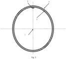
- the telescoping sections 3 are designed with oval cross-section.
- the telescoping section can be provided with other cross-sectional shapes, e.g. circular.
- a guide rail 6 runs in axial direction in parallel with a central axis of the telescopic member 2.
- the central axis is indicated by 7.
- Fig. 3 shows a spacer means 8, which is also shown in Fig. 1 .
- the spacer means 8 is intended for mounting on the other telescoping section 4.
- the spacer means 8 comprises a mounting fitting 9 provided with an inner cavity 10.
- a resilient sleeve 11 is provided in the cavity 10 .
- the resilient, elastic sleeve 11 has a hole 12.
- a pin 13 from a slide shoe 14 is received in the hole 12.
- the slide shoe 14 includes also a groove 15 dimensioned such that it can interact with the slide rail 6.
- the pin 13 is mounted rotationally in the hole 12 for rotation about a central axis 16 through the mounting fitting 9.
- FIG. 1 there is only one sectional view showing a mounting means 8.
- several mounting means 8 interacting with the guide rail 6 may be provided along the length of a telescopic member 2.
- the telescopic member 2 there may be provided several guide rails 6 that are distributed along the periphery of the one telescoping section 3. This is not shown, but the guide rails 6 will be evenly distributed along the periphery in a number that may be three or more such that a centring of the second telescoping section 4 inside the first telescoping section 3 is achieved.
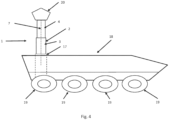
- Fig. 4 shows that the telescopic member 2 is disposed inside a third telescoping section 17.
- the telescopic mast 1 is mounted on a vehicle 18.
- the vehicle 18 is provided with wheels 19, but may alternatively be provided with tracks.
- a payload 20 is provided at the top of the telescopic mast 1.
- This payload 20 may, for example, be antenna equipment, surveillance equipment, lamps, weapons or other equipment.
Landscapes
- Engineering & Computer Science (AREA)
- Architecture (AREA)
- Civil Engineering (AREA)
- Structural Engineering (AREA)
- General Engineering & Computer Science (AREA)
- Mechanical Engineering (AREA)
- Forklifts And Lifting Vehicles (AREA)
Description
- The present invention concerns a telescopic mast including at least one or more telescopic members with parallel walls, where one of two adjacent telescoping sections is narrower than the other of the two adjacent telescoping sections, so that one telescoping section can be moved into and out of, respectively, of a surrounding telescoping section in a telescopic member as well as the latter can be moved into and out of a further telescopic member, where in the one telescoping section in a telescopic member there is provided a guide rail running in axial direction of the telescoping section, and where between each of two adjacent telescoping sections in a telescopic member there is provided at least one spacer means arranged for keeping the telescoping sections apart and controlling their mutual movement.
- There are many kinds of telescopic masts of which some can be extended automatically. In connection with such telescopic masts, for example for military applications, there are special requirements to practicability as well as to operability in extreme situations and weather conditions.
- For example,
US5540017A1 . disclose a telescopic flagpole which comprises at least two concentrically disposed tubular segments that are axially movable with respect to each other.US20130239490A1 disclose a telescoping structure including a hollow outer section and a hollow inner section slidably arranged in the hollow outer section. - Telescopic masts can be very high and may be used for sensors and weapons as well as for pointing out targets. High telescopic masts contain many telescoping sections. As play occurs between all adjacent telescoping sections of the mast, the play will accumulate in connection with high masts. Therefore, not the least in connection with high telescopic masts, it will very appropriate to minimise the play appearing between adjacent telescoping sections.
- There exist telescopic masts where in the gap between two adjacent telescoping sections means are provided that include actuators and/or mechanisms that may reduce play by e.g. pressing the adjacent walls away from each other. These means contribute to reducing play but are technically complicated and add an undesirable increase in weight.
- It is expedient if the part elements of the telescopic mast are not heavier and larger than necessary. In order to live up to requirements for reliability and sturdy construction, it is a clear disadvantage for a telescopic mast if the technology comprises frail technical solutions wherein failures may arise, causing the telescopic mast not be operated rapidly, accurately and under all conditions.
- There is also a need for a solution which in a simple way counteracts rotational movement about the longitudinal axis of the mast sections on telescopic masts with one or more extendable telescopic members.
- Telescopic masts used in environments with high loads are subjected to static as well as dynamic loads. These can e.g. be caused by wind loads as well as loads arising from mobile use.
- These loads can be very high G-loads that arise suddenly. They occur with random magnitudes and directions and provide a very complex load picture.
- These loads can arise from the top where a payload is mounted and/or from the bottom of the telescopic mast in the case of a mobile base/platform.
- The rotational control can/will be exposed to very large loads.
- It is desired to counteract rotational movement about the longitudinal axis of the mast sections in telescopic masts used on mobile platforms, e.g. vehicles, and where there is a requirement or wish for minimal rotation between the sections about the central axis of the mast, as the load/payload placed on the mast may require controlling the direction as viewed from the central axis of the mast. This may be communications antennae, radars, sensors, weapons, etc.
- In connection with high telescopic masts it is thus very advantageous if these are built up of simple components which irrespectively of the conditions provide a simple and uncomplicated use and operation of the telescopic mast, and which minimises play and counteracts mutual rotational movement of the telescopic sections about the longitudinal axis of the mast. None of the prior art solutions fulfil these demands.
-
US 4,357,785 A discloses a telescopic mast of the kind mentioned in the introduction having a telescoping section including guide rails running in axial direction of the telescoping section and spacer means mounted on another telescoping section by means of mounting fittings and interacting with the guide rails. - The object of the present invention is to provide a telescopic mast where the play between the telescoping sections is minimised. It is a further object of the invention to provide a telescopic mast that counteracts mutual rotational movement of the telescoping section, and which is light.
- As indicated by introduction, the present invention concerns a telescopic mast including at least one or more telescopic members with parallel walls, where one of two adjacent telescoping sections is narrower than the other of the two adjacent telescoping sections, so that one telescoping section can be moved into and out of, respectively, of a surrounding telescoping section in a telescopic member as well as the latter can be moved into and out of a further telescopic member, where in the one telescoping section in a telescopic member there is provided a guide rail running in axial direction of the telescoping section, and where between each of two adjacent telescoping sections in a telescopic member there is provided at least one spacer means arranged for keeping the telescoping sections apart and controlling their mutual movement. The telescopic mast is peculiar by including a mounting fitting fastened to the second telescoping section in a telescopic member and a flexible sleeve mounted in the mounting fitting, where in the flexible sleeve there is mounted a slide shoe including a pin for engaging the flexible sleeve and a groove arranged for engaging the guide rail.
- By a telescopic mast according to the invention is achieved reduction in play and rotational control with additional advantages.
- The part elements can be produced with much tighter tolerances that provide minimal play.
- The solution is very compact as suppression is provided by flexible and resilient material in the sleeve. The material for making the sleeve is elastically yielding such that by action of force the position of the hole and thereby the slide shoe can be changed relative to the mounting fitting under load, and that the sleeve is biased to return to its initial shape after removal of the load.
- Deformations and/or movement in and between the telescoping sections of the mast increasing the loads on guide rail/slide shoe are not all to be absorbed as loads in the material but are mitigated in the flexible material
The action of these complex combinations of shock-loads in multiple directions and simultaneously is not only to be absorbed as loads in/between slide shoe and slide rail, but will be absorbed and mitigated in the flexible material. - A telescopic mast according to the invention may advantageously be designed so that a pipe is provided inside the telescoping sections. Supply lines and cables of various kinds used in connection with equipment disposed at the top of the telescopic mast may be arranged in this pipe. For example, this may be antenna equipment, surveillance equipment, lamps, weapons or other equipment.
- By a telescopic mast according to the invention is thus achieved a number of advantages as the spacer means that resiliently keeps the adjacent walls away from each other minimises the play occurring between adjacent telescoping sections. By pressing the adjacent walls away from each other, the play is eliminated or minimised.
- Furthermore, by the telescopic mast according to the invention is achieved an advantage in that the groove of the slide shoe interacts with the guide rail, thereby preventing mutual rotational movement of the telescoping sections about the longitudinal axis of the mast. The construction, which consists of individual elements, will also be a simple and light construction.
- By the design is also achieved an advantage in that impact and blow actions are absorbed in the flexible sleeve between the groove engaging the guide rail on one telescoping section and the mounting fitting that is fastened to the other telescoping section.
- Spacer means of different nature with regard to design as well as material may be used. It can be advantageous to make the slide shoe and the sleeve of materials that are dimensionally stable in connection with large temperature fluctuations.
- It may furthermore be advantageous to apply a coating on the slide shoe, the sleeve and/or the guide rail comprising a layer of friction reducing material, as e.g. Teflon, for minimising friction between and wear of the elements involved.
- According to a further embodiment, the telescopic mast according to the invention is peculiar in that the guide rail in each telescopic member is provided on an inwardly facing side of one telescoping section, and that the mounting fitting is provided on an outwardly side of the other telescoping section.
- In practice, it has appeared expedient if the guide rail or rails in each telescopic member is provided on an inwardly facing side with the purpose of a simple design. The mounting fitting will hereby be placed on an outwardly facing side of the second telescoping section provided inside the first telescoping section. Alternatively, it is possible to arrange this disposition oppositely such that the guide rail in each telescopic member is provided on an outwardly facing side of the internal telescoping section in a telescopic member.
- According to a further embodiment, the telescopic mast according to the invention is peculiar in that the flexible sleeve is made of a flexible material such that the slide shoe can be displaced radially or axially relative to a central axis through the mounting fitting. As the flexible sleeve is made of a flexible material allowing displacement in several dimensions, there is ensured the highest degree of absorption of shock actions, reducing wear, and at the same time is achieved rotational fixing between the different telescoping sections.
- Since the slide shoe can be displaced radially as well as axially relative to a central axis through the mounting fitting, shock actions are absorbed irrespectively of the direction thereof.
- According to a further embodiment, the telescopic mast according to the invention is peculiar in that the flexible sleeve is made with a mounting hole for receiving the pin of the slide shoe, and that the pin of the slide shoe can rotate in the mounting hole in the sleeve. By making the connection between the pin of the slide shoe and the hole in the sleeve without fixation, the rotation in the mounting hole will ensure that also twisting between the two telescoping sections can be absorbed in the flexible sleeve. Also, a rotation of the pin of the slide shoe will enable using guide rails that do not run completely axially but may have an inclination relative to an axial direction which is parallel with a central axis through the telescopic mast.
- According to a further embodiment, the telescopic mast according to the invention is peculiar in that for each telescopic member there is provided three or more guide rails distributed along the periphery of the telescopic member. By applying several guide rails distributed along the periphery of the telescopic member, there is achieved an even distribution that absorbs the play as well as provides the rotationally fixed distribution. By the even distribution of the guide rails and thereby also of the interacting spacer means there may be established a centring of the inner telescoping section in an outer telescoping section in a telescopic member. Thus there may be a single guide rail in a telescopic member, but there may as well be two or more guide rails in a telescopic member.
- According to a further embodiment, the telescopic mast according to the invention is peculiar in that for each guide rail there are provided two or more spacer means distributed in axial direction of the telescopic member. In order to distribute a load and secure an orientation against rotation two or more spacer means distributed in the telescopic member may be provided, distributed in axial direction of the telescopic member. By such an assembly torsional twisting of one telescoping section relative to the other telescoping section in a telescopic member is prevented.
- The invention is described in more detail with reference to the drawing, wherein:
- Fig. 1
- shows a section through a telescopic member in telescopic mast according to the invention in which a guide rail interacts with a spacer means disposed on each their telescoping section in a telescopic member;
- Fig. 2
- shows a cross-section through one telescoping section with a guide rail running in axial direction of the telescoping section;
- Fig. 3
- shows a section through a spacer means intended for being provided on the other telescoping section in a telescopic member; and
- Fig. 4
- shows a schematic drawing of a telescopic mast mounted on a vehicle.
-
-
Figs. 1-3 show various sectional views of the same design. -
Fig. 1 shows atelescopic mast 1 appearing with a section through a singletelescopic member 2. Thetelescopic member 2 comprises afirst telescoping section 3 and asecond telescoping section 4. Thetelescoping section 4 has smaller dimension than thefirst telescoping section 3 such that thesecond telescoping section 4 can be moved in over thefirst telescoping section 3 in thetelescopic member 2. It is possible to provide a third telescoping section 17 (seeFig. 4 ) around the shown telescopic member, or a further telescoping section (not shown), which is disposed within the showntelescopic member 2. - In the shown embodiment, the
telescoping sections 3 are designed with oval cross-section. Alternatively, the telescoping section can be provided with other cross-sectional shapes, e.g. circular. - As it appears more clearly on
Fig. 2 , at aninner side 5 of thefirst telescoping section 3 there is provided aguide rail 6. Theguide rail 6 runs in axial direction in parallel with a central axis of thetelescopic member 2. The central axis is indicated by 7. -
Fig. 3 shows a spacer means 8, which is also shown inFig. 1 . The spacer means 8 is intended for mounting on theother telescoping section 4. The spacer means 8 comprises a mounting fitting 9 provided with aninner cavity 10. In the cavity 10 aresilient sleeve 11 is provided. The resilient,elastic sleeve 11 has ahole 12. Apin 13 from aslide shoe 14 is received in thehole 12. Theslide shoe 14 includes also agroove 15 dimensioned such that it can interact with theslide rail 6. Thepin 13 is mounted rotationally in thehole 12 for rotation about acentral axis 16 through the mounting fitting 9. - In the shown embodiment there is only one sectional view showing a mounting means 8. However, several mounting means 8 interacting with the
guide rail 6 may be provided along the length of atelescopic member 2. - Moreover, in the
telescopic member 2 there may be providedseveral guide rails 6 that are distributed along the periphery of the onetelescoping section 3. This is not shown, but theguide rails 6 will be evenly distributed along the periphery in a number that may be three or more such that a centring of thesecond telescoping section 4 inside thefirst telescoping section 3 is achieved. -
Fig. 4 shows that thetelescopic member 2 is disposed inside athird telescoping section 17. Thetelescopic mast 1 is mounted on avehicle 18. Thevehicle 18 is provided withwheels 19, but may alternatively be provided with tracks. Apayload 20 is provided at the top of thetelescopic mast 1. Thispayload 20 may, for example, be antenna equipment, surveillance equipment, lamps, weapons or other equipment.
Claims (6)
- A telescopic mast (1) including at least one telescopic member (2) with parallel walls, said telescopic member comprising a first telescoping section (3) and a second telescoping section (4)- where one of the two adjacent first and second telescoping sections (3, 4) is narrower than the other of the two adjacent telescoping sections (3, 4), so that one telescoping section (4) can be moved into and out of, respectively, of a surrounding telescoping section (3) in a telescopic member (2) as well as the latter can be moved into and out of a further telescopic member (2),- a guide rail (6) positioned within one of the telescoping sections (3) and running in an axial direction of the one of the telescoping sections (3),- characterised in that the telescopic mast (1) includes- at least one spacer means (8) arranged between each of the two adjacent telescoping sections (3,4) for keeping the telescoping sections (3, 4) apart and controlling the respective mutual movement of the telescoping sections (3,4), comprising a mounting fitting (9) fastened to the second telescoping section (4) in the telescopic member, and- a flexible sleeve (11) mounted in the mounting fitting (9), and- a slide shoe (14) mounted within the flexible sleeve, the slide shoe (14) including a pin (13) for engaging the flexible sleeve (11) and a groove (15) arranged for engaging the guide rail (6).
- Telescopic mast (1) according to claim 1, characterised in that the guide rail (6) in each telescopic member is provided on an inwardly facing side (6) of one telescoping section, and that the mounting fitting (9) is provided on an outwardly side of the other telescoping section (4).
- Telescopic mast (1) according to claim 1 or 2, characterised in that the flexible sleeve (11) is made of a flexible material such that the slide shoe (14) is displaceable radially or axially relative to a central axis (16) through the mounting fitting (9).
- Telescopic mast (1) according to any preceding claim, characterised in that the flexible sleeve (11) is made with a mounting hole (12) for receiving the pin (13) of the slide shoe (14), and that the pin (13) of the slide shoe (14) is rotatable in the mounting hole (12).
- Telescopic mast (1) according to any preceding claim, characterised in that for each telescopic member (2) there is provided three or more guide rails (6) distributed along the periphery of the telescopic member (2).
- Telescopic mast according to any preceding claim, characterised in that for each guide rail (6) there is provided two or more spacer means (8) distributed in axial direction of the telescopic member (2).
Applications Claiming Priority (2)
| Application Number | Priority Date | Filing Date | Title |
|---|---|---|---|
| DKPA201770947A DK179825B1 (en) | 2017-12-15 | 2017-12-15 | Telescopic Mast |
| PCT/DK2018/050357 WO2019114907A1 (en) | 2017-12-15 | 2018-12-13 | Telescopic mast |
Publications (4)
| Publication Number | Publication Date |
|---|---|
| EP3724426A1 EP3724426A1 (en) | 2020-10-21 |
| EP3724426A4 EP3724426A4 (en) | 2021-08-04 |
| EP3724426C0 EP3724426C0 (en) | 2023-08-30 |
| EP3724426B1 true EP3724426B1 (en) | 2023-08-30 |
Family
ID=66819950
Family Applications (1)
| Application Number | Title | Priority Date | Filing Date |
|---|---|---|---|
| EP18887264.2A Active EP3724426B1 (en) | 2017-12-15 | 2018-12-13 | Telescopic mast |
Country Status (6)
| Country | Link |
|---|---|
| US (1) | US11408193B2 (en) |
| EP (1) | EP3724426B1 (en) |
| AU (1) | AU2018386263B2 (en) |
| CA (1) | CA3085228A1 (en) |
| DK (1) | DK179825B1 (en) |
| WO (1) | WO2019114907A1 (en) |
Families Citing this family (2)
| Publication number | Priority date | Publication date | Assignee | Title |
|---|---|---|---|---|
| US12270430B2 (en) * | 2019-10-15 | 2025-04-08 | MJ Engineering LLC | Layered multi-body support structure |
| US11346122B2 (en) * | 2019-10-15 | 2022-05-31 | M J Engineering LLC | Layered multi-body support structure |
Family Cites Families (14)
| Publication number | Priority date | Publication date | Assignee | Title |
|---|---|---|---|---|
| SE343177B (en) | 1966-11-28 | 1972-02-28 | Vaegbelysning Ab | |
| DE2603488C3 (en) * | 1976-01-30 | 1979-02-22 | Dornier System Gmbh, 7990 Friedrichshafen | Telescopically variable-length device, in particular boom support arm or the like, e.g. for remote-controlled devices, in particular for space technology |
| SE415901B (en) | 1979-02-09 | 1980-11-10 | Erik Eklund | TELESCOPIC MAST |
| US4918896A (en) * | 1988-10-17 | 1990-04-24 | Harold Wiese | Telescopic flagpole |
| DK0520534T3 (en) * | 1991-06-28 | 1994-10-10 | Omeca Spa | Telescopic extension of vacuum cleaners |
| US5540017A (en) * | 1995-01-09 | 1996-07-30 | Jil Industries Limited Partnership | Telescopic flagpole |
| IT249874Y1 (en) * | 2000-11-07 | 2003-06-05 | Omec Spa | TELESCOPIC EXTENSION FOR A HOME APPLIANCE |
| US6767115B2 (en) * | 2001-11-16 | 2004-07-27 | The Will-Burt Company | Pneumatic telescoping mast |
| NL1020345C2 (en) | 2001-12-17 | 2003-06-18 | Ballast Nedam Eng | Wind turbine, has adjustable distance between gondola and part for connecting mast to foundation |
| US8522511B2 (en) * | 2010-12-20 | 2013-09-03 | Raytheon Company | Methods and apparatus for mast system with enhanced load bearing |
| CN103307069A (en) * | 2012-03-13 | 2013-09-18 | 鸿富锦精密工业(深圳)有限公司 | Multi-section telescopic device |
| US9371663B2 (en) * | 2014-05-07 | 2016-06-21 | Us Tower Corporation | Internally keyed extruded mast system |
| DE102015205355A1 (en) * | 2015-03-24 | 2016-09-29 | Aktiebolaget Skf | Lifting column |
| ITUB20161063A1 (en) * | 2016-02-25 | 2017-08-25 | Omec Spa | Compact telescopic extension for a household appliance and related appliance |
-
2017
- 2017-12-15 DK DKPA201770947A patent/DK179825B1/en active IP Right Grant
-
2018
- 2018-12-13 US US16/772,791 patent/US11408193B2/en active Active
- 2018-12-13 EP EP18887264.2A patent/EP3724426B1/en active Active
- 2018-12-13 AU AU2018386263A patent/AU2018386263B2/en active Active
- 2018-12-13 CA CA3085228A patent/CA3085228A1/en active Pending
- 2018-12-13 WO PCT/DK2018/050357 patent/WO2019114907A1/en not_active Ceased
Also Published As
| Publication number | Publication date |
|---|---|
| EP3724426A1 (en) | 2020-10-21 |
| AU2018386263A1 (en) | 2020-07-30 |
| US11408193B2 (en) | 2022-08-09 |
| DK201770947A1 (en) | 2019-07-08 |
| AU2018386263B2 (en) | 2024-02-15 |
| DK179825B1 (en) | 2019-07-15 |
| EP3724426C0 (en) | 2023-08-30 |
| CA3085228A1 (en) | 2019-06-20 |
| EP3724426A4 (en) | 2021-08-04 |
| WO2019114907A1 (en) | 2019-06-20 |
| US20200362586A1 (en) | 2020-11-19 |
Similar Documents
| Publication | Publication Date | Title |
|---|---|---|
| US8522511B2 (en) | Methods and apparatus for mast system with enhanced load bearing | |
| US4357785A (en) | Telescopic mast | |
| EP3724426B1 (en) | Telescopic mast | |
| DE60318614T2 (en) | Latch for fixing the segment of an optical space telescope | |
| EP2634467B1 (en) | Tube support structure for aircraft | |
| US20120151852A1 (en) | Methods and apparatus for antenna having guy wire telescoping | |
| EP2845797B1 (en) | Arrangement for guiding a cable between a wing and an aerodynamic body movably supported relative thereto; wing of an aircraft having such an arrangement and aircraft having such a wing | |
| CN102593571B (en) | Scissors-based quadrilateral unit planar array developable mechanism | |
| US20150211250A1 (en) | Telescopic mast | |
| KR102127082B1 (en) | Antenna positioning mechanism | |
| EP3788217B1 (en) | Telescopic mast | |
| US9546718B2 (en) | System comprising a roller screw and a roller thrust bearing | |
| CN102398864A (en) | Telescopic mechanism, engineering machinery and fire-fighting machinery | |
| US11834202B2 (en) | Device for deploying and pointing an equipment item carried by a spacecraft | |
| US6987492B1 (en) | Tetrahedral positioner for an antenna | |
| EP3038912B1 (en) | Swashplate apparatus | |
| UA126297C2 (en) | Foldable light tower | |
| CN202503095U (en) | Scissor-based quadrangle element planar array extendable mechanism | |
| RU173218U1 (en) | Coaxial Helicopter Rotor System | |
| US20170167532A1 (en) | Bearing and bearing device | |
| US9614355B2 (en) | Portable electrical substation racking mechanism | |
| RU2645197C1 (en) | Electromechanical lifting device with the mechanism of actuation the limit switch | |
| NZ743421B2 (en) | Compact stabilized pointing system | |
| NZ743421A (en) | Compact stabilized pointing system | |
| JP2013005598A (en) | Protective tube movable support structure for bridge |
Legal Events
| Date | Code | Title | Description |
|---|---|---|---|
| STAA | Information on the status of an ep patent application or granted ep patent |
Free format text: STATUS: THE INTERNATIONAL PUBLICATION HAS BEEN MADE |
|
| PUAI | Public reference made under article 153(3) epc to a published international application that has entered the european phase |
Free format text: ORIGINAL CODE: 0009012 |
|
| STAA | Information on the status of an ep patent application or granted ep patent |
Free format text: STATUS: REQUEST FOR EXAMINATION WAS MADE |
|
| 17P | Request for examination filed |
Effective date: 20200701 |
|
| AK | Designated contracting states |
Kind code of ref document: A1 Designated state(s): AL AT BE BG CH CY CZ DE DK EE ES FI FR GB GR HR HU IE IS IT LI LT LU LV MC MK MT NL NO PL PT RO RS SE SI SK SM TR |
|
| AX | Request for extension of the european patent |
Extension state: BA ME |
|
| DAV | Request for validation of the european patent (deleted) | ||
| DAX | Request for extension of the european patent (deleted) | ||
| A4 | Supplementary search report drawn up and despatched |
Effective date: 20210705 |
|
| RIC1 | Information provided on ipc code assigned before grant |
Ipc: E04H 12/18 20060101AFI20210629BHEP Ipc: B60Q 1/26 20060101ALI20210629BHEP |
|
| 19U | Interruption of proceedings before grant |
Effective date: 20210816 |
|
| 19W | Proceedings resumed before grant after interruption of proceedings |
Effective date: 20221102 |
|
| RAP3 | Party data changed (applicant data changed or rights of an application transferred) |
Owner name: FALCK-SCHMIDT APS |
|
| RIN1 | Information on inventor provided before grant (corrected) |
Inventor name: FALCK-SCHMIDT APS |
|
| RIN1 | Information on inventor provided before grant (corrected) |
Inventor name: FALCK-SCHMIDT, JAN |
|
| GRAP | Despatch of communication of intention to grant a patent |
Free format text: ORIGINAL CODE: EPIDOSNIGR1 |
|
| STAA | Information on the status of an ep patent application or granted ep patent |
Free format text: STATUS: GRANT OF PATENT IS INTENDED |
|
| RIC1 | Information provided on ipc code assigned before grant |
Ipc: B60Q 1/26 20060101ALI20230328BHEP Ipc: E04H 12/18 20060101AFI20230328BHEP |
|
| INTG | Intention to grant announced |
Effective date: 20230414 |
|
| GRAS | Grant fee paid |
Free format text: ORIGINAL CODE: EPIDOSNIGR3 |
|
| GRAA | (expected) grant |
Free format text: ORIGINAL CODE: 0009210 |
|
| STAA | Information on the status of an ep patent application or granted ep patent |
Free format text: STATUS: THE PATENT HAS BEEN GRANTED |
|
| AK | Designated contracting states |
Kind code of ref document: B1 Designated state(s): AL AT BE BG CH CY CZ DE DK EE ES FI FR GB GR HR HU IE IS IT LI LT LU LV MC MK MT NL NO PL PT RO RS SE SI SK SM TR |
|
| REG | Reference to a national code |
Ref country code: GB Ref legal event code: FG4D |
|
| REG | Reference to a national code |
Ref country code: CH Ref legal event code: EP |
|
| REG | Reference to a national code |
Ref country code: DE Ref legal event code: R096 Ref document number: 602018056727 Country of ref document: DE |
|
| REG | Reference to a national code |
Ref country code: IE Ref legal event code: FG4D |
|
| U01 | Request for unitary effect filed |
Effective date: 20230926 |
|
| U07 | Unitary effect registered |
Designated state(s): AT BE BG DE DK EE FI FR IT LT LU LV MT NL PT SE SI Effective date: 20231004 |
|
| PG25 | Lapsed in a contracting state [announced via postgrant information from national office to epo] |
Ref country code: GR Free format text: LAPSE BECAUSE OF FAILURE TO SUBMIT A TRANSLATION OF THE DESCRIPTION OR TO PAY THE FEE WITHIN THE PRESCRIBED TIME-LIMIT Effective date: 20231201 |
|
| PG25 | Lapsed in a contracting state [announced via postgrant information from national office to epo] |
Ref country code: IS Free format text: LAPSE BECAUSE OF FAILURE TO SUBMIT A TRANSLATION OF THE DESCRIPTION OR TO PAY THE FEE WITHIN THE PRESCRIBED TIME-LIMIT Effective date: 20231230 |
|
| PG25 | Lapsed in a contracting state [announced via postgrant information from national office to epo] |
Ref country code: RS Free format text: LAPSE BECAUSE OF FAILURE TO SUBMIT A TRANSLATION OF THE DESCRIPTION OR TO PAY THE FEE WITHIN THE PRESCRIBED TIME-LIMIT Effective date: 20230830 Ref country code: NO Free format text: LAPSE BECAUSE OF FAILURE TO SUBMIT A TRANSLATION OF THE DESCRIPTION OR TO PAY THE FEE WITHIN THE PRESCRIBED TIME-LIMIT Effective date: 20231130 Ref country code: IS Free format text: LAPSE BECAUSE OF FAILURE TO SUBMIT A TRANSLATION OF THE DESCRIPTION OR TO PAY THE FEE WITHIN THE PRESCRIBED TIME-LIMIT Effective date: 20231230 Ref country code: HR Free format text: LAPSE BECAUSE OF FAILURE TO SUBMIT A TRANSLATION OF THE DESCRIPTION OR TO PAY THE FEE WITHIN THE PRESCRIBED TIME-LIMIT Effective date: 20230830 Ref country code: GR Free format text: LAPSE BECAUSE OF FAILURE TO SUBMIT A TRANSLATION OF THE DESCRIPTION OR TO PAY THE FEE WITHIN THE PRESCRIBED TIME-LIMIT Effective date: 20231201 |
|
| U20 | Renewal fee for the european patent with unitary effect paid |
Year of fee payment: 6 Effective date: 20231227 |
|
| PG25 | Lapsed in a contracting state [announced via postgrant information from national office to epo] |
Ref country code: PL Free format text: LAPSE BECAUSE OF FAILURE TO SUBMIT A TRANSLATION OF THE DESCRIPTION OR TO PAY THE FEE WITHIN THE PRESCRIBED TIME-LIMIT Effective date: 20230830 |
|
| PG25 | Lapsed in a contracting state [announced via postgrant information from national office to epo] |
Ref country code: ES Free format text: LAPSE BECAUSE OF FAILURE TO SUBMIT A TRANSLATION OF THE DESCRIPTION OR TO PAY THE FEE WITHIN THE PRESCRIBED TIME-LIMIT Effective date: 20230830 |
|
| PG25 | Lapsed in a contracting state [announced via postgrant information from national office to epo] |
Ref country code: SM Free format text: LAPSE BECAUSE OF FAILURE TO SUBMIT A TRANSLATION OF THE DESCRIPTION OR TO PAY THE FEE WITHIN THE PRESCRIBED TIME-LIMIT Effective date: 20230830 Ref country code: RO Free format text: LAPSE BECAUSE OF FAILURE TO SUBMIT A TRANSLATION OF THE DESCRIPTION OR TO PAY THE FEE WITHIN THE PRESCRIBED TIME-LIMIT Effective date: 20230830 Ref country code: ES Free format text: LAPSE BECAUSE OF FAILURE TO SUBMIT A TRANSLATION OF THE DESCRIPTION OR TO PAY THE FEE WITHIN THE PRESCRIBED TIME-LIMIT Effective date: 20230830 Ref country code: CZ Free format text: LAPSE BECAUSE OF FAILURE TO SUBMIT A TRANSLATION OF THE DESCRIPTION OR TO PAY THE FEE WITHIN THE PRESCRIBED TIME-LIMIT Effective date: 20230830 Ref country code: SK Free format text: LAPSE BECAUSE OF FAILURE TO SUBMIT A TRANSLATION OF THE DESCRIPTION OR TO PAY THE FEE WITHIN THE PRESCRIBED TIME-LIMIT Effective date: 20230830 |
|
| REG | Reference to a national code |
Ref country code: DE Ref legal event code: R097 Ref document number: 602018056727 Country of ref document: DE |
|
| PLBE | No opposition filed within time limit |
Free format text: ORIGINAL CODE: 0009261 |
|
| STAA | Information on the status of an ep patent application or granted ep patent |
Free format text: STATUS: NO OPPOSITION FILED WITHIN TIME LIMIT |
|
| REG | Reference to a national code |
Ref country code: CH Ref legal event code: PL |
|
| 26N | No opposition filed |
Effective date: 20240603 |
|
| PG25 | Lapsed in a contracting state [announced via postgrant information from national office to epo] |
Ref country code: MC Free format text: LAPSE BECAUSE OF FAILURE TO SUBMIT A TRANSLATION OF THE DESCRIPTION OR TO PAY THE FEE WITHIN THE PRESCRIBED TIME-LIMIT Effective date: 20230830 |
|
| PG25 | Lapsed in a contracting state [announced via postgrant information from national office to epo] |
Ref country code: MC Free format text: LAPSE BECAUSE OF FAILURE TO SUBMIT A TRANSLATION OF THE DESCRIPTION OR TO PAY THE FEE WITHIN THE PRESCRIBED TIME-LIMIT Effective date: 20230830 |
|
| REG | Reference to a national code |
Ref country code: IE Ref legal event code: MM4A |
|
| PG25 | Lapsed in a contracting state [announced via postgrant information from national office to epo] |
Ref country code: IE Free format text: LAPSE BECAUSE OF NON-PAYMENT OF DUE FEES Effective date: 20231213 |
|
| PG25 | Lapsed in a contracting state [announced via postgrant information from national office to epo] |
Ref country code: CH Free format text: LAPSE BECAUSE OF NON-PAYMENT OF DUE FEES Effective date: 20231231 |
|
| PG25 | Lapsed in a contracting state [announced via postgrant information from national office to epo] |
Ref country code: IE Free format text: LAPSE BECAUSE OF NON-PAYMENT OF DUE FEES Effective date: 20231213 Ref country code: CH Free format text: LAPSE BECAUSE OF NON-PAYMENT OF DUE FEES Effective date: 20231231 |
|
| U20 | Renewal fee for the european patent with unitary effect paid |
Year of fee payment: 7 Effective date: 20241227 |
|
| PG25 | Lapsed in a contracting state [announced via postgrant information from national office to epo] |
Ref country code: CY Free format text: LAPSE BECAUSE OF FAILURE TO SUBMIT A TRANSLATION OF THE DESCRIPTION OR TO PAY THE FEE WITHIN THE PRESCRIBED TIME-LIMIT; INVALID AB INITIO Effective date: 20181213 |
|
| PG25 | Lapsed in a contracting state [announced via postgrant information from national office to epo] |
Ref country code: HU Free format text: LAPSE BECAUSE OF FAILURE TO SUBMIT A TRANSLATION OF THE DESCRIPTION OR TO PAY THE FEE WITHIN THE PRESCRIBED TIME-LIMIT; INVALID AB INITIO Effective date: 20181213 |
|
| PG25 | Lapsed in a contracting state [announced via postgrant information from national office to epo] |
Ref country code: TR Free format text: LAPSE BECAUSE OF FAILURE TO SUBMIT A TRANSLATION OF THE DESCRIPTION OR TO PAY THE FEE WITHIN THE PRESCRIBED TIME-LIMIT Effective date: 20230830 |
|
| PGFP | Annual fee paid to national office [announced via postgrant information from national office to epo] |
Ref country code: GB Payment date: 20251229 Year of fee payment: 8 |
|
| U20 | Renewal fee for the european patent with unitary effect paid |
Year of fee payment: 8 Effective date: 20251229 |