EP3724124B1 - Crane with wheels having variable camber angle - Google Patents
Crane with wheels having variable camber angle Download PDFInfo
- Publication number
- EP3724124B1 EP3724124B1 EP18830531.2A EP18830531A EP3724124B1 EP 3724124 B1 EP3724124 B1 EP 3724124B1 EP 18830531 A EP18830531 A EP 18830531A EP 3724124 B1 EP3724124 B1 EP 3724124B1
- Authority
- EP
- European Patent Office
- Prior art keywords
- wheels
- crane
- wheel
- camber angle
- drive
- Prior art date
- Legal status (The legal status is an assumption and is not a legal conclusion. Google has not performed a legal analysis and makes no representation as to the accuracy of the status listed.)
- Active
Links
Images




Classifications
-
- B—PERFORMING OPERATIONS; TRANSPORTING
- B66—HOISTING; LIFTING; HAULING
- B66F—HOISTING, LIFTING, HAULING OR PUSHING, NOT OTHERWISE PROVIDED FOR, e.g. DEVICES WHICH APPLY A LIFTING OR PUSHING FORCE DIRECTLY TO THE SURFACE OF A LOAD
- B66F9/00—Devices for lifting or lowering bulky or heavy goods for loading or unloading purposes
- B66F9/06—Devices for lifting or lowering bulky or heavy goods for loading or unloading purposes movable, with their loads, on wheels or the like, e.g. fork-lift trucks
- B66F9/075—Constructional features or details
- B66F9/07568—Steering arrangements
-
- B—PERFORMING OPERATIONS; TRANSPORTING
- B62—LAND VEHICLES FOR TRAVELLING OTHERWISE THAN ON RAILS
- B62D—MOTOR VEHICLES; TRAILERS
- B62D17/00—Means on vehicles for adjusting camber, castor, or toe-in
-
- B—PERFORMING OPERATIONS; TRANSPORTING
- B60—VEHICLES IN GENERAL
- B60G—VEHICLE SUSPENSION ARRANGEMENTS
- B60G17/00—Resilient suspensions having means for adjusting the spring or vibration-damper characteristics, for regulating the distance between a supporting surface and a sprung part of vehicle or for locking suspension during use to meet varying vehicular or surface conditions, e.g. due to speed or load
- B60G17/015—Resilient suspensions having means for adjusting the spring or vibration-damper characteristics, for regulating the distance between a supporting surface and a sprung part of vehicle or for locking suspension during use to meet varying vehicular or surface conditions, e.g. due to speed or load the regulating means comprising electric or electronic elements
- B60G17/016—Resilient suspensions having means for adjusting the spring or vibration-damper characteristics, for regulating the distance between a supporting surface and a sprung part of vehicle or for locking suspension during use to meet varying vehicular or surface conditions, e.g. due to speed or load the regulating means comprising electric or electronic elements characterised by their responsiveness, when the vehicle is travelling, to specific motion, a specific condition, or driver input
- B60G17/0165—Resilient suspensions having means for adjusting the spring or vibration-damper characteristics, for regulating the distance between a supporting surface and a sprung part of vehicle or for locking suspension during use to meet varying vehicular or surface conditions, e.g. due to speed or load the regulating means comprising electric or electronic elements characterised by their responsiveness, when the vehicle is travelling, to specific motion, a specific condition, or driver input to an external condition, e.g. rough road surface, side wind
-
- B—PERFORMING OPERATIONS; TRANSPORTING
- B60—VEHICLES IN GENERAL
- B60G—VEHICLE SUSPENSION ARRANGEMENTS
- B60G17/00—Resilient suspensions having means for adjusting the spring or vibration-damper characteristics, for regulating the distance between a supporting surface and a sprung part of vehicle or for locking suspension during use to meet varying vehicular or surface conditions, e.g. due to speed or load
- B60G17/015—Resilient suspensions having means for adjusting the spring or vibration-damper characteristics, for regulating the distance between a supporting surface and a sprung part of vehicle or for locking suspension during use to meet varying vehicular or surface conditions, e.g. due to speed or load the regulating means comprising electric or electronic elements
- B60G17/017—Resilient suspensions having means for adjusting the spring or vibration-damper characteristics, for regulating the distance between a supporting surface and a sprung part of vehicle or for locking suspension during use to meet varying vehicular or surface conditions, e.g. due to speed or load the regulating means comprising electric or electronic elements characterised by their use when the vehicle is stationary, e.g. during loading, engine start-up or switch-off
-
- B—PERFORMING OPERATIONS; TRANSPORTING
- B60—VEHICLES IN GENERAL
- B60K—ARRANGEMENT OR MOUNTING OF PROPULSION UNITS OR OF TRANSMISSIONS IN VEHICLES; ARRANGEMENT OR MOUNTING OF PLURAL DIVERSE PRIME-MOVERS IN VEHICLES; AUXILIARY DRIVES FOR VEHICLES; INSTRUMENTATION OR DASHBOARDS FOR VEHICLES; ARRANGEMENTS IN CONNECTION WITH COOLING, AIR INTAKE, GAS EXHAUST OR FUEL SUPPLY OF PROPULSION UNITS IN VEHICLES
- B60K17/00—Arrangement or mounting of transmissions in vehicles
- B60K17/04—Arrangement or mounting of transmissions in vehicles characterised by arrangement, location or kind of gearing
- B60K17/043—Transmission unit disposed in on near the vehicle wheel, or between the differential gear unit and the wheel
- B60K17/046—Transmission unit disposed in on near the vehicle wheel, or between the differential gear unit and the wheel with planetary gearing having orbital motion
-
- B—PERFORMING OPERATIONS; TRANSPORTING
- B60—VEHICLES IN GENERAL
- B60K—ARRANGEMENT OR MOUNTING OF PROPULSION UNITS OR OF TRANSMISSIONS IN VEHICLES; ARRANGEMENT OR MOUNTING OF PLURAL DIVERSE PRIME-MOVERS IN VEHICLES; AUXILIARY DRIVES FOR VEHICLES; INSTRUMENTATION OR DASHBOARDS FOR VEHICLES; ARRANGEMENTS IN CONNECTION WITH COOLING, AIR INTAKE, GAS EXHAUST OR FUEL SUPPLY OF PROPULSION UNITS IN VEHICLES
- B60K7/00—Disposition of motor in, or adjacent to, traction wheel
- B60K7/0007—Disposition of motor in, or adjacent to, traction wheel the motor being electric
-
- B—PERFORMING OPERATIONS; TRANSPORTING
- B66—HOISTING; LIFTING; HAULING
- B66C—CRANES; LOAD-ENGAGING ELEMENTS OR DEVICES FOR CRANES, CAPSTANS, WINCHES, OR TACKLES
- B66C23/00—Cranes comprising essentially a beam, boom, or triangular structure acting as a cantilever and mounted for translatory of swinging movements in vertical or horizontal planes or a combination of such movements, e.g. jib-cranes, derricks, tower cranes
- B66C23/18—Cranes comprising essentially a beam, boom, or triangular structure acting as a cantilever and mounted for translatory of swinging movements in vertical or horizontal planes or a combination of such movements, e.g. jib-cranes, derricks, tower cranes specially adapted for use in particular purposes
- B66C23/36—Cranes comprising essentially a beam, boom, or triangular structure acting as a cantilever and mounted for translatory of swinging movements in vertical or horizontal planes or a combination of such movements, e.g. jib-cranes, derricks, tower cranes specially adapted for use in particular purposes mounted on road or rail vehicles; Manually-movable jib-cranes for use in workshops; Floating cranes
-
- B—PERFORMING OPERATIONS; TRANSPORTING
- B66—HOISTING; LIFTING; HAULING
- B66C—CRANES; LOAD-ENGAGING ELEMENTS OR DEVICES FOR CRANES, CAPSTANS, WINCHES, OR TACKLES
- B66C23/00—Cranes comprising essentially a beam, boom, or triangular structure acting as a cantilever and mounted for translatory of swinging movements in vertical or horizontal planes or a combination of such movements, e.g. jib-cranes, derricks, tower cranes
- B66C23/18—Cranes comprising essentially a beam, boom, or triangular structure acting as a cantilever and mounted for translatory of swinging movements in vertical or horizontal planes or a combination of such movements, e.g. jib-cranes, derricks, tower cranes specially adapted for use in particular purposes
- B66C23/36—Cranes comprising essentially a beam, boom, or triangular structure acting as a cantilever and mounted for translatory of swinging movements in vertical or horizontal planes or a combination of such movements, e.g. jib-cranes, derricks, tower cranes specially adapted for use in particular purposes mounted on road or rail vehicles; Manually-movable jib-cranes for use in workshops; Floating cranes
- B66C23/42—Cranes comprising essentially a beam, boom, or triangular structure acting as a cantilever and mounted for translatory of swinging movements in vertical or horizontal planes or a combination of such movements, e.g. jib-cranes, derricks, tower cranes specially adapted for use in particular purposes mounted on road or rail vehicles; Manually-movable jib-cranes for use in workshops; Floating cranes with jibs of adjustable configuration, e.g. foldable
-
- B—PERFORMING OPERATIONS; TRANSPORTING
- B66—HOISTING; LIFTING; HAULING
- B66C—CRANES; LOAD-ENGAGING ELEMENTS OR DEVICES FOR CRANES, CAPSTANS, WINCHES, OR TACKLES
- B66C23/00—Cranes comprising essentially a beam, boom, or triangular structure acting as a cantilever and mounted for translatory of swinging movements in vertical or horizontal planes or a combination of such movements, e.g. jib-cranes, derricks, tower cranes
- B66C23/62—Constructional features or details
-
- B—PERFORMING OPERATIONS; TRANSPORTING
- B60—VEHICLES IN GENERAL
- B60G—VEHICLE SUSPENSION ARRANGEMENTS
- B60G2200/00—Indexing codes relating to suspension types
- B60G2200/40—Indexing codes relating to the wheels in the suspensions
- B60G2200/44—Indexing codes relating to the wheels in the suspensions steerable
-
- B—PERFORMING OPERATIONS; TRANSPORTING
- B60—VEHICLES IN GENERAL
- B60G—VEHICLE SUSPENSION ARRANGEMENTS
- B60G2200/00—Indexing codes relating to suspension types
- B60G2200/40—Indexing codes relating to the wheels in the suspensions
- B60G2200/46—Indexing codes relating to the wheels in the suspensions camber angle
-
- B—PERFORMING OPERATIONS; TRANSPORTING
- B60—VEHICLES IN GENERAL
- B60G—VEHICLE SUSPENSION ARRANGEMENTS
- B60G2202/00—Indexing codes relating to the type of spring, damper or actuator
- B60G2202/40—Type of actuator
- B60G2202/41—Fluid actuator
- B60G2202/413—Hydraulic actuator
-
- B—PERFORMING OPERATIONS; TRANSPORTING
- B60—VEHICLES IN GENERAL
- B60G—VEHICLE SUSPENSION ARRANGEMENTS
- B60G2300/00—Indexing codes relating to the type of vehicle
- B60G2300/06—Cranes
-
- B—PERFORMING OPERATIONS; TRANSPORTING
- B60—VEHICLES IN GENERAL
- B60G—VEHICLE SUSPENSION ARRANGEMENTS
- B60G2400/00—Indexing codes relating to detected, measured or calculated conditions or factors
- B60G2400/80—Exterior conditions
- B60G2400/82—Ground surface
- B60G2400/823—Obstacle sensing
-
- B—PERFORMING OPERATIONS; TRANSPORTING
- B60—VEHICLES IN GENERAL
- B60G—VEHICLE SUSPENSION ARRANGEMENTS
- B60G2800/00—Indexing codes relating to the type of movement or to the condition of the vehicle and to the end result to be achieved by the control action
- B60G2800/01—Attitude or posture control
- B60G2800/019—Inclination due to load distribution or road gradient
-
- B—PERFORMING OPERATIONS; TRANSPORTING
- B60—VEHICLES IN GENERAL
- B60K—ARRANGEMENT OR MOUNTING OF PROPULSION UNITS OR OF TRANSMISSIONS IN VEHICLES; ARRANGEMENT OR MOUNTING OF PLURAL DIVERSE PRIME-MOVERS IN VEHICLES; AUXILIARY DRIVES FOR VEHICLES; INSTRUMENTATION OR DASHBOARDS FOR VEHICLES; ARRANGEMENTS IN CONNECTION WITH COOLING, AIR INTAKE, GAS EXHAUST OR FUEL SUPPLY OF PROPULSION UNITS IN VEHICLES
- B60K7/00—Disposition of motor in, or adjacent to, traction wheel
- B60K2007/0092—Disposition of motor in, or adjacent to, traction wheel the motor axle being coaxial to the wheel axle
Definitions
- the invention relates to a crane on wheels for lifting and moving loads.
- the crane has a plurality of wheels in order to move on the support surface, which can be a smooth floor, such as in a factory, or a bulky or uneven surface, such as in an outdoor environment.
- Some of these wheels are drive wheels.
- the wheels are capable of rotating so as to allow the crane to move, but they are mounted in a rigid manner relative to the frame of the crane.
- a drawback of known cranes lies in the fact that they are not capable of ensuring a good drive on irregular support surfaces, i.e. bulky or uneven surfaces. Indeed, when the wheels rest on an uneven surface, they barely generate a friction with the surface; this situation makes it difficult or even impossible for the crane to move on the surface.
- GB 202034 A in an automobile crane, which is both steered and slued by means of the road wheels, one or more pairs of road wheels, swivelled for this purpose, are mounted on inclined stub axles so as to bring the wheels close together on the ground. These axles can rise and fall relatively to the steering-pillar, and can pivot about a horizontal axis to facilitate movement over uneven ground. It is described in connection with a crane having front and rear pairs of steering-wheels and two pairs of side wheels, one wheel of each pair being driven through reduction gear by a motor.
- GB 202034 A discloses a crane according to the preamble of the independent claim 1.
- WO 88/02329 A1 discloses a method of improving the balance of a vehicle and friction in a lateral direction, with changes in the direction of forward movement.
- the negative effect of the centrifugal force on balance and friction is counteracted by changed wheel angles from the axle point in a lateral direction towards the outer extremity of the curve, longitudinally in the changed forward direction, made possible by redistribution of part of the vehicle mass (weight) in a direction towards the inner extremity of the curve.
- GB 2334015 A discloses a base structure for a mobile access platform includes a chassis having at least two pairs of wheels, first one of said pairs of wheels including a suspension mechanism including, for each wheel, a swing arm member on which the wheel is mounted, said swing arm member being arranged to pivot about a substantially horizontal pivot axis, a stop member arranged to engage the swing arm member so as to limit upwards movement thereof, and biassing means arranged exert a biassing force on the swing arm member to urge the swing arm member upwards towards the stop member.
- the biassing force is less than the force needed to maintain the swing arm member in engagement with the stop member when the wheel is unsupported.
- the arrangement is such that the swing arm members normally engage the stop members when the mobile access platform is standing on flat, level ground.
- a bolt is connected to the swing arm, passes through the stop member and the biasing spring acts between the bolt and the stop member to bias the arm upwards.
- GB 2506944 A discloses a base unit for a vehicle such as a mobile work platform comprising of chassis and a plurality of wheels at least one of which being mounted on the chassis by a suspension mechanism which may comprise of a swing arm that can pivot relative to the chassis about a pivot axis between an upper position and a lower position, and a stop member arranged to limit upwards movement.
- the suspension may comprise a double wishbone or short-long arm suspension.
- a biasing mechanism urges the suspension element upwards.
- the biasing mechanism includes an actuator operable to urge the suspension element towards the lower position.
- the base unit may include an adjuster device such as adjustable bolt.
- the suspension mechanism may include a drive device for driving the wheels and at least one wheel may be rigidly mounted to the base.
- the vehicle may include a lifting mechanism mounted on the base unit and a control system for the lifting mechanism which may be configured to prevent actuation of the actuator when in a lifted condition.
- An object of the invention is to provide a crane for lifting and moving loads, which is able to solve this and other drawbacks of the prior art and which, at the same time, can be produced in a simple and economic fashion.
- one of the technical problems solved by the invention is that of providing a crane for lifting and moving loads, which is capable of ensuring a good friction with the different support surfaces.
- a crane for lifting and moving loads comprising: a base frame 12, adapted to transfer the loads of crane 10 onto a support surface by means of a plurality of wheels 34, 35, 36.
- at least one wheel 34, 35, 36 is capable of rotating relative to said base frame 12 so as to change camber angle A of said wheel.
- At least one wheel 34, 35, 36 (which can be a drive wheel or a driven wheel) is capable of rotating relative to base frame 12 so as to change camber angle A.
- wheel 36 can rotate around a camber axis y-y of said wheel 36.
- Camber axis y-y of the wheel can also be meant as a roll angle of the wheel.
- camber axis y-y is perpendicular to rolling axis x-x of the wheel 36.
- camber axis y-y preferably is horizontal. Through the rotation around camber axis y-y, the wheel can change its camber angle A.
- figures 1a-c relate, in a non-limiting manner, to a pair of twin wheels 36.
- a return means such as an elastic means (for example, a spring), preferably tends to move wheel 34, 35, 36 to a position in which camber angle A is equal to zero. For instance, when the crane is on a horizontal support surface, the return means tends to move wheel 34, 35, 36 to a vertical position (in which camber angle A is equal to zero).
- This solution allows wheels 34, 35, 36 to have a better drive, as they adjust to the irregularities of the ground.
- a further advantage lies in the fact that wheel 34, 35, 36 with a variable camber angle A damages the floor on which it is going to rest to a smaller extent.
- some wheels 34, 36 are drive wheel and the other wheels 35 are driven wheels.
- the other wheels 35 are driven wheels.
- one or more wheels 34 are steering wheels.
- a plurality of wheels 34, 35, 36 is capable of rotating relative to said base frame 12 so as to change camber angle A of said wheels.
- all wheels 34, 35, 36 are capable of changing camber angle A.
- the wheel can assume a negative and/or positive camber angle A.
- there are four wheels 34, 35 and two wheels 34 can change their camber angle A.
- At least one wheel 34 which is capable of changing its camber angle A, is a drive wheel.
- at least one wheels 34 are drive wheels.
- wheels 34 which are capable of changing their camber angle A, are drive wheels.
- the two wheels 34 are also drive wheels.
- all wheels are drive wheels; therefore, the crane is provided with a four-wheel drive or six-wheel drive system.
- drive wheels 34, 35, 36 are provided with respective motors 37, preferably electric or hydraulic motors.
- Motor 37 of each drive wheel preferably acts independently of the other ones.
- the crane comprises at least one motor 37 associated with a respective drive wheel and configured to operate it causing the rolling thereof (i.e. rotation around axis x-x, with reference to figures 1a-c ).
- the crane comprises at least one pair of twin wheels 36, which are capable of rotating relative to said base frame 12 so as to change camber angle A of said twin wheels 36.
- twin wheels 36 are adapted to rotate around rolling axis x-x independently of one another, but they assume the same camber angle A. This solution also allows for a reduction of the torque needed to steer on the support surface, especially in case twin wheels 36 are configured to steer. Indeed, when the weight of crane and of the load is considerable, there is a great sliding friction between the wheel and the support surface, which makes it difficult for the steering wheels to be steered.
- twin wheels 36 are integral in their rotation around rolling axis x-x.
- At least one pair of twin wheels 36 is designed to be operated by a respective motor 37 associated with said pair.
- motors 37 can act in an independent manner, conveniently coordinated by a control unit.
- the two wheels 36 belonging to said pair of twin wheels 36 are constrained by means of a differential device or differential.
- the differential can be of a known type and is conveniently similar to the one used in the automotive industry.
- the differential which is conveniently connected to a drive shaft of motor 37, transmits a torque from motor 37 to the respective twin wheels 36.
- the differential is interposed between the two wheels 36.
- the differential allows motor 37 to transmit a torque to the two wheels 36, allowing at the same time said wheels 36 to rotate with different angular speeds.
- the rotation speed of the two twin wheels 36 around of rolling axis x-x is adjusted through the differential. Therefore, the angular speed of the wheels 36 can be equal or different relative to one another.
- This allows the crane to steer, decreasing the friction between wheels 36 and the ground, and to reduce the wear of wheels 36.
- This aspect is particularly advantageous in case wheels 36 are configured to steer, but it is anyway advantageous also in case wheels 36 are not configured to steer.
- each pair of twin wheels 36 capable of changing their camber angle A.
- said pairs of twin wheels 36 are drive wheels and each pair of drive twin wheels 36 is associated with a respective motor 37 and a respective differential.
- each motor 37 is associated with a respective differential device.
- At least one wheel 34 is a steering wheel; in particular, there are different steering wheels, which, in the example shown herein, are the two rear wheels 34.
- steering wheels 34 are driven wheels (or free wheels).
- the two wheels 34 are steering and driven wheels.
- steering wheels 34 are also drive wheels.
- steering wheels 34 are drive wheels and they are also capable of rotating relative to base frame 12 so as to change their camber angle A.
- the wheel (single wheel 34, 35 or twin wheel 36) with a variable camber angle can be a non-steering wheel, a steering wheel, a drive wheel or a driven wheel.
- support element 38 which supports twin wheels 36 (with freedom of rotation around rolling axis x-x) and is fixed in a rotary manner to base frame 12 (only a portion thereof is shown).
- the rotation of support element 38 allows camber angle A of twin wheels 36 to be changed.
- support element 38 is interposed between the twin wheels 36.
- support element 38 comprises a pin 40, which is integral to it and can rotate relative to base frame 12.
- pin 40 is inserted, with freedom to rotate, in a housing portion 42, which is fixed in a removable manner (for example, through bolts) to the base frame 12, for instance to a bracket 44, which is fixed to base frame 12.
- y-y indicates the camber axis around which pin 40 and, hence, wheel 36 can rotate in order to change camber angle A.
- Rolling axis x-x lies on a plane that is perpendicular to camber axis y-y of twin wheels 36 and, in particular, these axes x-x and y-y are incident. According to an alternative variant, these axes x-x and y-y are not incident.
- middle planes B of twin wheels 36 are spaced apart - and, in particular, equally spaced apart - from camber axis y-y. Middle planes B are parallel to camber axis y-y.
- a mechanism can be used to change camber angle A, as described for the case of twin wheels 36.
- the middle plane of single wheel 34, 35 can include camber axis y-y or be spaced apart from it.
- the drive wheels are those wheels 34, 35, 36 that transfer the greatest force onto the support surface, when the crane carries the load.
- the crane has four wheel assemblies, each one consisting of one single wheel 34, 36 or of twin wheels 36, and the two front wheel assemblies comprise the drive wheels. By so doing, the friction between the drive wheels and the support surface can be maximized.
- said at least one drive wheel having the variable camber angle
- said at least one drive wheel is self-braking; for example, motor 37 is self-braking.
- motor 37 is self-braking.
- self-braking wheel 34, 35, 36 can also be a steering wheel.
- FIGS 3 and 4 show two steering wheels 34, in particular rear wheels.
- the crane preferably comprises a steering system including a linear steering actuator 46 (for example, a hydraulic jack), which is hinged, on one side, to base frame 12 and, on the other side, to a bar 48 having two ends.
- a linear steering actuator 46 for example, a hydraulic jack
- Each end of bar 48 is hinged to a respective rotary element 50, 52 around a respective hinging axis P1, P2, each rotary element 50, 52 being constrained, in its rotation, to respective wheel 34, so as to steer it.
- Each rotary element 50, 52 being able to rotate around a respective rotation axis R1, R2.
- rotary element 50, 52 is constrained, in its rotation, to the respective wheel 34 by means of gears.
- each steering wheel 34 is integral to a respective toothed gear 39, which meshes with a toothed surface on the respective rotary element 50, 52. Therefore, the rotation of rotary element 50, 52 controls the rotation of wheel 34 around a steering axis S1, S2 (which generally is vertical) of wheel 34.
- rotary element 50, 52 can be a disc, or a semi-disc, or a toothed gear.
- the steering system advantageously allows users to facilitate the control of the steering, thus avoiding sudden movements of the crane when it is moving.
- a further advantage lies in the fact that steering angles ⁇ 1, ⁇ 2 assumed by steering wheels 34 are not equal to one another when they 34 are in a steered position.
- rolling axes r1, r2 of steering wheels 34 are not parallel to one another when they 34 are in a steered position (see figure 5 ).
- rolling axes r1, r2 correspond to axis x-x of figures 1a-b .
- a further advantage lies in the fact that users can obtain a reduced steering radius of the crane, minimizing the friction between wheels 34 and the ground. Therefore, the crane can steer around a point that is substantially on a rolling axis r3 of non-steering wheels 35.
- rolling axes r1, r2 of steering wheels 34 define a sliding angle a, which advantageously is small or equal to zero, and, hence, the friction generated between wheels 34 and the ground is remarkably reduced.
- the distance between the hinging axes P1, P2 of bar 48 is smaller than the distance between rotation axes R1, R2 of rotary elements 50, 52.
- Rotation axes R1, R2 are parallel to steering axes S1, S2 (which conveniently are vertical) of wheels 34.
- Bar 48 is adapted to translate in a plane, for example a horizontal plane.
- the distance between rotation axes R1, R2 of rotary elements 50, 52 is smaller than the distance between steering axes S1, S2 of wheels 34.
- linear steering actuator 46 is hinged to a bracket 54, which is rigidly fixed, in particular welded, to bar 48.
- the ends of bar 48 are hinged to two brackets 56, 58, each bracket 56, 58 being rigidly fixed, in particular welded, to the respective rotary element 50, 52.
- linear steering actuator 46 is hinged to bar 48.
- the ends of bar 48 are hinged to the respective rotary element 50, 52; in particular, rotary element 50, 52 is a disc, and bar 48 is hinged to said disc close to the circumference of said disc.
- an arm 18 for lifting and transporting loads which is capable of rotating relative to said base frame 12 around a vertical axis.
- arm 18 is also - though not exclusively - capable of moving around a substantially vertical axis.
- the arm can be of a known type, for example it can be telescopic, or it can consist of different portions articulated to one another, etc.
- stabilizers 32 which are constrained to base frame 12 and, preferably, are extractable in a known manner.
- stabilizers 32 there are four stabilizers 32, in particular located at the vertexes of a rectangle in plan view.
- crane 10 comprises:
- the crane includes a pair of connecting rod elements 22, each connecting rod element 22 being hinged to turret 14 and to arm 18, so as to create an articulated quadrilateral.
- a first linear actuator 24 fitted on turret 14 and hinged to arm 18, which is capable of causing the lifting movement of arm 18.
- figure 2 shows an articulated quadrilateral, which is defined by the points indicated with letters A, B, C, D.
- turret 14 has a pair of brackets 15, in particular arranged vertically.
- a respective pair of connecting rod elements 22 pivots on each bracket 15. Therefore, there are two pairs of connecting rod elements 22, substantially arranged on the sides of the arm 18.
- arm 18 is telescopic and comprises sliding segments controlled by a second linear actuator 26.
- a first segment 18a is constrained to turret 14 in a movable manner and at least one further segment can slide relative to the first segment 18a.
- the second linear actuator 26 is adapted to perform the extraction/retraction of the segments, so as to increase/decrease the reach of arm 18.
- the top end of the first linear actuator 24 is hinged to the first segment 18a.
- linear actuators 24, 26, or at least one of them are hydraulic jacks.
- at least one of linear actuators 24, 26 is a hydraulic jack with two simultaneous stages. Connecting rod elements 22 are hinged to the first segment 18a.
- arm 18 is provided with means for attaching and transporting the loads, such as, for example, a clamp, tongs, a hook 30, or a platform, etc.
- arm 18 is associated with a winch system or a hoist, in order to move the loads.
- Said winch is conveniently activated by a motor means, such as an electric motor.
- the winch (or hoist) is associated with a hook 30, or the like, which can be extracted or retracted by operating the winch.
- the control tools can comprise, for example, pushbuttons, levers, screens, warning lights, sirens, indicators of different types, thus allowing the user to receive signals of various kinds regarding the operation of crane 10.
- Crane 10 preferably comprises at least one electric battery, which can be of the rechargeable type or not.
- the battery is rechargeable and can be recharged without being removed from the crane through suitable battery recharging means, for example by connecting the battery recharging means to an industrial or domestic socket outlet.
- the battery is adapted to supply the power required to carry out one or more of the following operations: activating the linear actuators; activating the signaling devices, among which there are the acoustic and visual ones; supplying power to the control system; activating the drive wheel; etc.
- arm 18 of crane 10 can be moved by means of a rope system, alternatively or in addition to linear actuator 24, 26.
- the crane is similar to the crane of figure 2 , as a matter of fact the same numbers of figure 2 indicate corresponding elements, which are not repeated only for the sake of brevity.
- the crane of figure 6 is not provided with a rotary turret (indicated with 14 in figure 2 ) and, hence, arm 18, conveniently a telescopic arm, is not capable of rotating relative to base frame 12 around a substantially vertical axis.
- brackets 15 are fixed (e.g. welded) to support columns 47, which are integral to base frame 12. Therefore, in order to rotate arm 18, crane 10 needs to be rotated on the ground by steering wheels 34.
- Crane 10 of the example comprises a steering system of the type described above with reference to figures 3-5 .
- crane 10 shown herein is simple, economic and compact.
- the preferred steering system allows the crane to rotate with a minimum steering radius, hence the crane is also agile in its movements.
- the crane preferably has movable platform 48, adapted to accommodate a user and is capable of assuming a retracted position, in which the space taken up by the crane is very small.
- movable platform 48 can rotate, conveniently around a horizontal axis; therefore, movable crane 48, when in the retracted position, is in a lifted position, in particular in a substantially vertical position shown in figure 6 .
- the crane has a remote control system (for example, an antenna 50 is shown), with which a user can control the movements of the crane, for example it is possible to control the movements of the crane on the support surface and the movements of arm 18.
- movable platform 48 is in the retracted position, thus minimizing the space occupied by the crane.
- the user decides to manually act upon the control of the crane (conveniently, by means of a control board 52), he moves movable platform 48 to an extracted position (conveniently, a horizontal position) and then he steps onto movable platform 48 to use the controls of the crane.
- Movable platform 48 preferably comprises sensors to detect the presence of or the contact with objects close to movable platform 48. This allows users to avoid undesired hits during the movement of the crane, when movable platform 48 is extracted.
- movable platform 48 comprises contact sensors placed on its edge, when it 48 is in the extracted position.
- movable platform 48 when movable platform 48 is in the retracted position, users cannot manually act upon the controls of the crane, in particular upon control board 52, and they can control the crane only in remote mode.
- users in order to use the controls to control the crane, users have to move the board to the extracted position (in the example, in a horizontal position).
- This feature is particularly safe because it prevents users from being hit by the crane when they act upon control board 52.
- a user is standing on movable platform 48, e cannot be hit by the crane.
Landscapes
- Engineering & Computer Science (AREA)
- Mechanical Engineering (AREA)
- Transportation (AREA)
- Chemical & Material Sciences (AREA)
- Combustion & Propulsion (AREA)
- Structural Engineering (AREA)
- Civil Engineering (AREA)
- Life Sciences & Earth Sciences (AREA)
- Geology (AREA)
- Jib Cranes (AREA)
Description
- The invention relates to a crane on wheels for lifting and moving loads.
- In the industrial field, as well as in the craft industry, the need to pick up, move and position loads at substantial distances from the pick-up point is well known.
- Generally speaking, the crane has a plurality of wheels in order to move on the support surface, which can be a smooth floor, such as in a factory, or a bulky or uneven surface, such as in an outdoor environment. Some of these wheels are drive wheels. The wheels are capable of rotating so as to allow the crane to move, but they are mounted in a rigid manner relative to the frame of the crane.
- A drawback of known cranes lies in the fact that they are not capable of ensuring a good drive on irregular support surfaces, i.e. bulky or uneven surfaces. Indeed, when the wheels rest on an uneven surface, they barely generate a friction with the surface; this situation makes it difficult or even impossible for the crane to move on the surface.
- According to
GB 202034 A GB 202034 A independent claim 1. -
WO 88/02329 A1 -
GB 2334015 A -
GB 2506944 A - An object of the invention is to provide a crane for lifting and moving loads, which is able to solve this and other drawbacks of the prior art and which, at the same time, can be produced in a simple and economic fashion.
- In particular, one of the technical problems solved by the invention is that of providing a crane for lifting and moving loads, which is capable of ensuring a good friction with the different support surfaces.
- According to the invention, this and other objects are reached by means of a crane having the features set forth in the appended independent claim.
- The appended claims are an integral part of the technical teaches provided in the following detailed description concerning the invention. In particular, the appended dependent claims define some preferred embodiments of the invention including optional technical features.
- Further features and advantages of the invention will be best understood upon perusal of the following detailed description, which is provided by way of example and is not limiting, with reference, in particular, to the accompanying drawings, wherein:
-
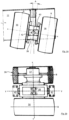
figure 1a is a front view of a pair of twin wheels with a variable camber angle, according to an embodiment of the invention; -
figure 1b is a plan view of the pair of twin wheels offigure 1a , wherein one wheel is partial; -
figure 1c is a side view of the pair of twin wheels offigure 1a , wherein one wheel is absent for a better understanding; -
figure 2 is a perspective view of a crane according to a particular variant of the invention; -
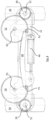
figure 3 is a plan view of some details of two steering wheels of the crane, according to a particular variant of the invention; -
figure 4 is a plan view of some details of two steering wheels of the crane, according to a further variant of the invention; -
figure 5 is a plan view of the wheels of the crane in an operating configuration, according to a particular variant of the invention; -
figure 6 is a side view of a crane according to a further variant of the invention. - With reference to the accompanying figures,
number 10 indicates, as a whole, a crane for lifting and moving loads comprising: abase frame 12, adapted to transfer the loads ofcrane 10 onto a support surface by means of a plurality ofwheels wheel base frame 12 so as to change camber angle A of said wheel. - Therefore, at least one
wheel base frame 12 so as to change camber angle A. Hence, with particular reference tofigures 1a-c ,wheel 36 can rotate around a camber axis y-y of saidwheel 36. Camber axis y-y of the wheel can also be meant as a roll angle of the wheel. In particular, camber axis y-y is perpendicular to rolling axis x-x of thewheel 36. When the crane is on a horizontal support surface, camber axis y-y preferably is horizontal. Through the rotation around camber axis y-y, the wheel can change its camber angle A. According to the description below,figures 1a-c relate, in a non-limiting manner, to a pair oftwin wheels 36. - A return means, such as an elastic means (for example, a spring), preferably tends to move
wheel wheel wheels wheel - For example, some
wheels other wheels 35 are driven wheels. In the example (figures 2-5 ) there are fourwheels more wheels 34 are steering wheels. In the example there are twosteering wheels 34 and two fixed wheels 35 (i.e. non-steering wheels). - Preferably, a plurality of
wheels base frame 12 so as to change camber angle A of said wheels. Optionally, allwheels wheels wheels 34 can change their camber angle A. - Preferably, at least one
wheel 34, which is capable of changing its camber angle A, is a drive wheel. Preferably, at least onewheels 34 are drive wheels. According to a particular variant,wheels 34, which are capable of changing their camber angle A, are drive wheels. With reference to the variant shown herein, the twowheels 34 are also drive wheels. Optionally, all wheels are drive wheels; therefore, the crane is provided with a four-wheel drive or six-wheel drive system. - According to a variant of the invention, drive
wheels respective motors 37, preferably electric or hydraulic motors.Motor 37 of each drive wheel preferably acts independently of the other ones. Hence, the crane comprises at least onemotor 37 associated with a respective drive wheel and configured to operate it causing the rolling thereof (i.e. rotation around axis x-x, with reference tofigures 1a-c ). - According to the variant of
figures 1a-c, the crane comprises at least one pair oftwin wheels 36, which are capable of rotating relative to saidbase frame 12 so as to change camber angle A of saidtwin wheels 36. According to a variant of the invention,twin wheels 36 are adapted to rotate around rolling axis x-x independently of one another, but they assume the same camber angle A. This solution also allows for a reduction of the torque needed to steer on the support surface, especially in casetwin wheels 36 are configured to steer. Indeed, when the weight of crane and of the load is considerable, there is a great sliding friction between the wheel and the support surface, which makes it difficult for the steering wheels to be steered. Alternatively,twin wheels 36 are integral in their rotation around rolling axis x-x. - At least one pair of
twin wheels 36 is designed to be operated by arespective motor 37 associated with said pair. In particular, there are different pairs oftwin wheels 36 and each pair is designed to be operated by arespective motor 37.Motors 37 can act in an independent manner, conveniently coordinated by a control unit. - The two
wheels 36 belonging to said pair oftwin wheels 36 are constrained by means of a differential device or differential. The differential can be of a known type and is conveniently similar to the one used in the automotive industry. The differential, which is conveniently connected to a drive shaft ofmotor 37, transmits a torque frommotor 37 to therespective twin wheels 36. For instance, the differential is interposed between the twowheels 36. Advantageously, the differential allowsmotor 37 to transmit a torque to the twowheels 36, allowing at the same time saidwheels 36 to rotate with different angular speeds. Hence, the rotation speed of the twotwin wheels 36 around of rolling axis x-x is adjusted through the differential. Therefore, the angular speed of thewheels 36 can be equal or different relative to one another. This allows the crane to steer, decreasing the friction betweenwheels 36 and the ground, and to reduce the wear ofwheels 36. This aspect is particularly advantageous incase wheels 36 are configured to steer, but it is anyway advantageous also incase wheels 36 are not configured to steer. - According to a particular embodiment of the invention, there are different pairs of
twin wheels 36 capable of changing their camber angle A. In particular, said pairs oftwin wheels 36 are drive wheels and each pair of drivetwin wheels 36 is associated with arespective motor 37 and a respective differential. In this case, therefore, eachmotor 37 is associated with a respective differential device. - Preferably, with particular reference to
figures 2-5 , at least onewheel 34 is a steering wheel; in particular, there are different steering wheels, which, in the example shown herein, are the tworear wheels 34. With reference to the variant shown by way of example,steering wheels 34 are driven wheels (or free wheels). In the example shown by way of example, the twowheels 34 are steering and driven wheels. Alternatively,steering wheels 34 are also drive wheels. According to a further possible variant,steering wheels 34 are drive wheels and they are also capable of rotating relative tobase frame 12 so as to change their camber angle A. - Hence, according to possible variants of the invention, the wheel (
single wheel - With reference to the details of
figures 1a-c , there is asupport element 38, which supports twin wheels 36 (with freedom of rotation around rolling axis x-x) and is fixed in a rotary manner to base frame 12 (only a portion thereof is shown). The rotation ofsupport element 38 allows camber angle A oftwin wheels 36 to be changed. In the example shown herein,support element 38 is interposed between thetwin wheels 36. In particular,support element 38 comprises apin 40, which is integral to it and can rotate relative tobase frame 12. In particular,pin 40 is inserted, with freedom to rotate, in ahousing portion 42, which is fixed in a removable manner (for example, through bolts) to thebase frame 12, for instance to abracket 44, which is fixed tobase frame 12. Infigure 1c , y-y indicates the camber axis around whichpin 40 and, hence,wheel 36 can rotate in order to change camber angle A. Rolling axis x-x lies on a plane that is perpendicular to camber axis y-y oftwin wheels 36 and, in particular, these axes x-x and y-y are incident. According to an alternative variant, these axes x-x and y-y are not incident. - With special reference to the example of
figures 1 a-c , middle planes B oftwin wheels 36 are spaced apart - and, in particular, equally spaced apart - from camber axis y-y. Middle planes B are parallel to camber axis y-y. - Even in case of a
single wheel twin wheels 36. According to possible variants, the middle plane ofsingle wheel - According to a particular variant, in case only some
wheels wheels single wheel twin wheels 36, and the two front wheel assemblies comprise the drive wheels. By so doing, the friction between the drive wheels and the support surface can be maximized. - Conveniently, said at least one drive wheel, having the variable camber angle, is self-braking; for example,
motor 37 is self-braking. When the user interrupts the "moving" command ofcrane 1, saidmotor 37 generates a braking action in order to stop the movement ofcrane 10 relative to the ground as soon as possible.Motor 37 can be of a known type, namely a hydraulic or electric motor. If necessary, self-brakingwheel -
Figures 3 and4 show twosteering wheels 34, in particular rear wheels. The crane preferably comprises a steering system including a linear steering actuator 46 (for example, a hydraulic jack), which is hinged, on one side, tobase frame 12 and, on the other side, to abar 48 having two ends. Each end ofbar 48 is hinged to arespective rotary element rotary element respective wheel 34, so as to steer it. Eachrotary element rotary element respective wheel 34 by means of gears. In particular, eachsteering wheel 34 is integral to a respectivetoothed gear 39, which meshes with a toothed surface on therespective rotary element rotary element wheel 34 around a steering axis S1, S2 (which generally is vertical) ofwheel 34. By way of example,rotary element wheels 34 are not equal to one another when they 34 are in a steered position. Hence, rolling axes r1, r2 ofsteering wheels 34 are not parallel to one another when they 34 are in a steered position (seefigure 5 ). As person skilled in the art clearly knows, rolling axes r1, r2 correspond to axis x-x offigures 1a-b . A further advantage lies in the fact that users can obtain a reduced steering radius of the crane, minimizing the friction betweenwheels 34 and the ground. Therefore, the crane can steer around a point that is substantially on a rolling axis r3 ofnon-steering wheels 35. According tofigure 5 , rolling axes r1, r2 ofsteering wheels 34 define a sliding angle a, which advantageously is small or equal to zero, and, hence, the friction generated betweenwheels 34 and the ground is remarkably reduced. - In particular, the distance between the hinging axes P1, P2 of
bar 48 is smaller than the distance between rotation axes R1, R2 ofrotary elements wheels 34.Bar 48 is adapted to translate in a plane, for example a horizontal plane. Preferably, the distance between rotation axes R1, R2 ofrotary elements wheels 34. - In particular, in
figure 3 ,linear steering actuator 46 is hinged to abracket 54, which is rigidly fixed, in particular welded, to bar 48. The ends ofbar 48 are hinged to twobrackets bracket respective rotary element - On the contrary, in the particular variant of
figure 4 ,linear steering actuator 46 is hinged to bar 48. The ends ofbar 48 are hinged to therespective rotary element rotary element - With reference to the variant shown, by way of non-limiting example, in
figure 2 , there is anarm 18 for lifting and transporting loads, which is capable of rotating relative to saidbase frame 12 around a vertical axis. Preferably,arm 18 is also - though not exclusively - capable of moving around a substantially vertical axis. Furthermore, the arm can be of a known type, for example it can be telescopic, or it can consist of different portions articulated to one another, etc. - Preferably, there are
stabilizers 32, which are constrained tobase frame 12 and, preferably, are extractable in a known manner. In the example there are fourstabilizers 32, in particular located at the vertexes of a rectangle in plan view. - For greater clarity, a non-limiting description of a
crane 10 having a particular structure and a preferred lifting mechanism is provided below. With particular reference to the variant shown,crane 10 comprises: -
base frame 12; - a turret 14, which is fixed to
base frame 12 so as to rotate, in particular around a substantially vertical axis, -
arm 18, adapted to move loads and is mounted on turret 14 in a movable manner. - In particular, the crane includes a pair of connecting
rod elements 22, each connectingrod element 22 being hinged to turret 14 and toarm 18, so as to create an articulated quadrilateral. There is a firstlinear actuator 24 fitted on turret 14 and hinged toarm 18, which is capable of causing the lifting movement ofarm 18. In a non-limiting manner,figure 2 shows an articulated quadrilateral, which is defined by the points indicated with letters A, B, C, D. - In particular, turret 14 has a pair of
brackets 15, in particular arranged vertically. A respective pair of connectingrod elements 22 pivots on eachbracket 15. Therefore, there are two pairs of connectingrod elements 22, substantially arranged on the sides of thearm 18. - Conveniently,
arm 18 is telescopic and comprises sliding segments controlled by a secondlinear actuator 26. Afirst segment 18a is constrained to turret 14 in a movable manner and at least one further segment can slide relative to thefirst segment 18a. The secondlinear actuator 26 is adapted to perform the extraction/retraction of the segments, so as to increase/decrease the reach ofarm 18. The top end of the firstlinear actuator 24 is hinged to thefirst segment 18a. Conveniently,linear actuators linear actuators Connecting rod elements 22 are hinged to thefirst segment 18a. - Preferably,
arm 18 is provided with means for attaching and transporting the loads, such as, for example, a clamp, tongs, ahook 30, or a platform, etc. For example,arm 18 is associated with a winch system or a hoist, in order to move the loads. Said winch is conveniently activated by a motor means, such as an electric motor. The winch (or hoist) is associated with ahook 30, or the like, which can be extracted or retracted by operating the winch. - The control tools can comprise, for example, pushbuttons, levers, screens, warning lights, sirens, indicators of different types, thus allowing the user to receive signals of various kinds regarding the operation of
crane 10. -
Crane 10 preferably comprises at least one electric battery, which can be of the rechargeable type or not. Conveniently, the battery is rechargeable and can be recharged without being removed from the crane through suitable battery recharging means, for example by connecting the battery recharging means to an industrial or domestic socket outlet. The battery is adapted to supply the power required to carry out one or more of the following operations: activating the linear actuators; activating the signaling devices, among which there are the acoustic and visual ones; supplying power to the control system; activating the drive wheel; etc. - According to further variants,
arm 18 ofcrane 10 can be moved by means of a rope system, alternatively or in addition tolinear actuator - With reference to the further variant shown, by way of non-limiting example, in
figure 6 , the crane is similar to the crane offigure 2 , as a matter of fact the same numbers offigure 2 indicate corresponding elements, which are not repeated only for the sake of brevity. The crane offigure 6 is not provided with a rotary turret (indicated with 14 infigure 2 ) and, hence,arm 18, conveniently a telescopic arm, is not capable of rotating relative tobase frame 12 around a substantially vertical axis. In the example,brackets 15 are fixed (e.g. welded) to supportcolumns 47, which are integral tobase frame 12. Therefore, in order to rotatearm 18,crane 10 needs to be rotated on the ground by steeringwheels 34.Crane 10 of the example comprises a steering system of the type described above with reference tofigures 3-5 . Hence,crane 10 shown herein is simple, economic and compact. The preferred steering system allows the crane to rotate with a minimum steering radius, hence the crane is also agile in its movements. - The crane preferably has
movable platform 48, adapted to accommodate a user and is capable of assuming a retracted position, in which the space taken up by the crane is very small. In particular,movable platform 48 can rotate, conveniently around a horizontal axis; therefore,movable crane 48, when in the retracted position, is in a lifted position, in particular in a substantially vertical position shown infigure 6 . The crane has a remote control system (for example, anantenna 50 is shown), with which a user can control the movements of the crane, for example it is possible to control the movements of the crane on the support surface and the movements ofarm 18. When the user uses the remote control system,movable platform 48 is in the retracted position, thus minimizing the space occupied by the crane. When, on the other hand, the user decides to manually act upon the control of the crane (conveniently, by means of a control board 52), he movesmovable platform 48 to an extracted position (conveniently, a horizontal position) and then he steps ontomovable platform 48 to use the controls of the crane. -
Movable platform 48 preferably comprises sensors to detect the presence of or the contact with objects close tomovable platform 48. This allows users to avoid undesired hits during the movement of the crane, whenmovable platform 48 is extracted. In particular,movable platform 48 comprises contact sensors placed on its edge, when it 48 is in the extracted position. - Preferably, when
movable platform 48 is in the retracted position, users cannot manually act upon the controls of the crane, in particular uponcontrol board 52, and they can control the crane only in remote mode. Hence, in order to use the controls to control the crane, users have to move the board to the extracted position (in the example, in a horizontal position). This feature is particularly safe because it prevents users from being hit by the crane when they act uponcontrol board 52. On the other hand, when a user is standing onmovable platform 48, e cannot be hit by the crane. - Naturally, the principle of the invention being set forth, embodiments and implementation details can be widely changed relative to what described above and shown in the drawings as a mere way of non-limiting example, without in this way going beyond the scope of protection provided by the accompanying claims.
Claims (8)
- A crane (10) for lifting and transporting loads comprising: a base frame (12), for transferring the loads of the crane (10) onto a support surface by means of a plurality of wheels (34, 35, 36),wherein at least one wheel (34, 35, 36) is capable of rotating relative to said base frame (12) so as to change the camber angle (A) of said wheel (34, 35, 36);the crane (10) comprises at least one pair of twin wheels (36), which are capable of rotating relative to said base frame (12) so as to change the camber angle (A) of said twin wheels (36);characterized in that said at least one pair of twin wheels (36) is adapted to be operated by a respective motor (37) associated with said pair; wherein the two wheels (36) belonging to said pair of twin wheels (36) are constrained by means of a differential device.
- Crane (10) according to claim 1 and comprising a return means, which tends to move said wheel (34, 35, 36) to a position in which the camber angle (A) is equal to zero.
- Crane (10) according to claim 1 or 2, comprising a plurality of wheels (34, 35, 36), which are capable of rotating relative to said base frame (12) so as to change the camber angle (A) of said wheels (34, 35, 36).
- Crane (10) according to any one of the preceding claims, comprising a plurality of drive wheels, which are provided with respective motors (37).
- Crane (10) according to any one of the preceding claims, wherein each wheel (34, 35, 36), which is capable of changing its camber angle (A), is a drive wheel.
- Crane (10) according to any one of the preceding claims, wherein, in case only some wheels (34, 35, 36) are drive wheels, the drive wheels are those wheels (34, 35, 36) that transfer the greatest force onto the support surface, when the crane (10) carries the load.
- Crane (10) according to any one of the preceding claims, wherein at least one wheel (34, 35, 36), which is capable of changing its camber angle (A) and is a drive wheel, is also self-braking.
- Crane (10) according to claims 3 and 4, wherein there is a plurality of pairs of twin wheels (36) capable of changing their camber angle (A), wherein said pairs of twin wheels (36) are drive wheels and each pair of drive twin wheels (36) is associated with a respective motor (37) and a respective differential device.
Applications Claiming Priority (2)
| Application Number | Priority Date | Filing Date | Title |
|---|---|---|---|
| IT201700142033 | 2017-12-11 | ||
| PCT/IB2018/059817 WO2019116193A1 (en) | 2017-12-11 | 2018-12-10 | Crane with wheels having variable camber angle |
Publications (2)
| Publication Number | Publication Date |
|---|---|
| EP3724124A1 EP3724124A1 (en) | 2020-10-21 |
| EP3724124B1 true EP3724124B1 (en) | 2023-06-14 |
Family
ID=61656216
Family Applications (1)
| Application Number | Title | Priority Date | Filing Date |
|---|---|---|---|
| EP18830531.2A Active EP3724124B1 (en) | 2017-12-11 | 2018-12-10 | Crane with wheels having variable camber angle |
Country Status (4)
| Country | Link |
|---|---|
| US (1) | US11524720B2 (en) |
| EP (1) | EP3724124B1 (en) |
| CA (1) | CA3085279A1 (en) |
| WO (1) | WO2019116193A1 (en) |
Families Citing this family (6)
| Publication number | Priority date | Publication date | Assignee | Title |
|---|---|---|---|---|
| CA3085279A1 (en) * | 2017-12-11 | 2019-06-20 | Jacques Tranchero | Crane with wheels having variable camber angle |
| IT201900020082A1 (en) * | 2019-10-30 | 2021-04-30 | Ces S R L | AXLE UNIT FOR SELF-PROPELLED OPERATING MACHINE |
| CN113968274B (en) * | 2021-12-01 | 2024-05-03 | 吉林大学 | Electric gear shifting double-mode rear wheel active steering system |
| IT202200014533A1 (en) * | 2022-07-11 | 2024-01-11 | Borghi Assali S R L | MOTORIZED WHEEL APPARATUS |
| IT202300001827A1 (en) * | 2023-02-06 | 2024-08-06 | Jacques Tranchero | CRANE WITH A WINCH PULL LIMITATION SYSTEM. |
| US11993495B1 (en) * | 2023-10-16 | 2024-05-28 | Altec Industries, Inc. | Aerial device |
Family Cites Families (14)
| Publication number | Priority date | Publication date | Assignee | Title |
|---|---|---|---|---|
| GB202034A (en) | 1922-05-10 | 1923-08-10 | Paul Alphonse Hubert Mossay | Improvements in automobile cranes |
| US2569861A (en) * | 1948-11-29 | 1951-10-02 | Murray L Moore | Dual wheel differential hub |
| US2727582A (en) * | 1952-10-30 | 1955-12-20 | Lisenby George Edward | Differentially driven dual wheels with locking means for the differential |
| US2773723A (en) * | 1953-07-31 | 1956-12-11 | Dualoc Engineering Co | Braking arrangement for dual wheels with non-torque-equalizing differential means |
| US2988400A (en) * | 1958-04-21 | 1961-06-13 | Charles S Ash | Demountable-rim differential dual wheel construction |
| US3154315A (en) * | 1961-07-19 | 1964-10-27 | Charles S Ash | Differential dual front wheel vehicle |
| SE8604050D0 (en) | 1986-09-25 | 1986-09-25 | Jan Kral | WHEEL ANGLE CONTROLLER AND LOAD DISTRIBUTOR |
| GB2334015B (en) * | 1998-02-10 | 2001-05-30 | Frank Roger Bowden | Base structure for a mobile access platform |
| US6267188B1 (en) * | 2000-03-22 | 2001-07-31 | Meritor Heavy Vehicle Systems, Llc | Drive assembly for independently driving vehicle wheels |
| IT1321227B1 (en) * | 2000-06-06 | 2003-12-31 | Montini & C S N C | CUSHIONED SUSPENSION FOR DRIVE MACHINES WITH TWO-WHEEL AXLE AXLE, PARTICULARLY FOR FOUR-WHEEL LIFT TRUCKS |
| WO2011065936A1 (en) * | 2009-11-24 | 2011-06-03 | Navistar Canada, Inc. | Independent dual wheel tractor drive |
| GB2506944B (en) * | 2012-10-15 | 2017-02-22 | Niftylift Ltd | Base unit for a vehicle |
| CN107487129A (en) * | 2017-08-16 | 2017-12-19 | 苏州凤凰动力工业有限公司 | Two-wheel differential steering driving wheel |
| CA3085279A1 (en) * | 2017-12-11 | 2019-06-20 | Jacques Tranchero | Crane with wheels having variable camber angle |
-
2018
- 2018-12-10 CA CA3085279A patent/CA3085279A1/en active Pending
- 2018-12-10 WO PCT/IB2018/059817 patent/WO2019116193A1/en not_active Ceased
- 2018-12-10 US US16/772,686 patent/US11524720B2/en active Active
- 2018-12-10 EP EP18830531.2A patent/EP3724124B1/en active Active
Also Published As
| Publication number | Publication date |
|---|---|
| US11524720B2 (en) | 2022-12-13 |
| WO2019116193A1 (en) | 2019-06-20 |
| CA3085279A1 (en) | 2019-06-20 |
| US20210362784A1 (en) | 2021-11-25 |
| EP3724124A1 (en) | 2020-10-21 |
Similar Documents
| Publication | Publication Date | Title |
|---|---|---|
| EP3724124B1 (en) | Crane with wheels having variable camber angle | |
| EP3560884B1 (en) | Material handling vehicle and a material handling system comprising such a vehicle | |
| EP0897368B1 (en) | Aircraft-wheel lifting device | |
| EP3606862B1 (en) | Crane with anti-tipping control system | |
| EP3724125B1 (en) | Crane comprising a steering system | |
| US3424475A (en) | Lift truck suspension system | |
| EP2906495B1 (en) | Base unit for a vehicle | |
| EP3068649B1 (en) | Appliance with motorized wheels | |
| CN112249980A (en) | Anti-tipping method and anti-tipping mechanism for three-fulcrum electric forklift | |
| CN116198629B (en) | AGV whole car device and AGV floating chassis device thereof | |
| US2187197A (en) | Industrial truck | |
| CN211710612U (en) | Drive Mechanisms and Automated Guided Transport Vehicles | |
| EP3927646B1 (en) | Electrically operated lifting unit for a working vehicle | |
| EP3470297B1 (en) | A drive unit for an industrial truck and an industrial truck with such a drive unit | |
| EP3191398B1 (en) | Crane for lifting and transporting loads comprising a roll-over protection system | |
| EP3191397B1 (en) | Improved crane for lifting and transporting loads | |
| EP3228525B1 (en) | Powered steering trolley and transport vehicle provided with such trolley | |
| RU187608U1 (en) | Mechanical loader | |
| JP6807287B2 (en) | Vehicle moving trolley | |
| CA2252901C (en) | Aircraft-wheel lifting device | |
| JP5935175B2 (en) | Lifting device for practicing skidding by motorcycle and apparatus equipped with such a lifting device |
Legal Events
| Date | Code | Title | Description |
|---|---|---|---|
| STAA | Information on the status of an ep patent application or granted ep patent |
Free format text: STATUS: UNKNOWN |
|
| STAA | Information on the status of an ep patent application or granted ep patent |
Free format text: STATUS: THE INTERNATIONAL PUBLICATION HAS BEEN MADE |
|
| PUAI | Public reference made under article 153(3) epc to a published international application that has entered the european phase |
Free format text: ORIGINAL CODE: 0009012 |
|
| STAA | Information on the status of an ep patent application or granted ep patent |
Free format text: STATUS: REQUEST FOR EXAMINATION WAS MADE |
|
| 17P | Request for examination filed |
Effective date: 20200707 |
|
| AK | Designated contracting states |
Kind code of ref document: A1 Designated state(s): AL AT BE BG CH CY CZ DE DK EE ES FI FR GB GR HR HU IE IS IT LI LT LU LV MC MK MT NL NO PL PT RO RS SE SI SK SM TR |
|
| AX | Request for extension of the european patent |
Extension state: BA ME |
|
| DAV | Request for validation of the european patent (deleted) | ||
| DAX | Request for extension of the european patent (deleted) | ||
| RIC1 | Information provided on ipc code assigned before grant |
Ipc: B60G 17/0165 20060101ALI20221109BHEP Ipc: B60G 17/017 20060101ALI20221109BHEP Ipc: B66C 23/36 20060101ALI20221109BHEP Ipc: B66C 23/62 20060101ALI20221109BHEP Ipc: B66F 9/075 20060101AFI20221109BHEP |
|
| GRAP | Despatch of communication of intention to grant a patent |
Free format text: ORIGINAL CODE: EPIDOSNIGR1 |
|
| STAA | Information on the status of an ep patent application or granted ep patent |
Free format text: STATUS: GRANT OF PATENT IS INTENDED |
|
| INTG | Intention to grant announced |
Effective date: 20230105 |
|
| GRAS | Grant fee paid |
Free format text: ORIGINAL CODE: EPIDOSNIGR3 |
|
| GRAA | (expected) grant |
Free format text: ORIGINAL CODE: 0009210 |
|
| STAA | Information on the status of an ep patent application or granted ep patent |
Free format text: STATUS: THE PATENT HAS BEEN GRANTED |
|
| AK | Designated contracting states |
Kind code of ref document: B1 Designated state(s): AL AT BE BG CH CY CZ DE DK EE ES FI FR GB GR HR HU IE IS IT LI LT LU LV MC MK MT NL NO PL PT RO RS SE SI SK SM TR |
|
| P01 | Opt-out of the competence of the unified patent court (upc) registered |
Effective date: 20230510 |
|
| REG | Reference to a national code |
Ref country code: CH Ref legal event code: EP |
|
| REG | Reference to a national code |
Ref country code: DE Ref legal event code: R096 Ref document number: 602018051923 Country of ref document: DE |
|
| REG | Reference to a national code |
Ref country code: AT Ref legal event code: REF Ref document number: 1579130 Country of ref document: AT Kind code of ref document: T Effective date: 20230715 |
|
| REG | Reference to a national code |
Ref country code: LT Ref legal event code: MG9D |
|
| REG | Reference to a national code |
Ref country code: NL Ref legal event code: MP Effective date: 20230614 |
|
| PG25 | Lapsed in a contracting state [announced via postgrant information from national office to epo] |
Ref country code: SE Free format text: LAPSE BECAUSE OF FAILURE TO SUBMIT A TRANSLATION OF THE DESCRIPTION OR TO PAY THE FEE WITHIN THE PRESCRIBED TIME-LIMIT Effective date: 20230614 Ref country code: NO Free format text: LAPSE BECAUSE OF FAILURE TO SUBMIT A TRANSLATION OF THE DESCRIPTION OR TO PAY THE FEE WITHIN THE PRESCRIBED TIME-LIMIT Effective date: 20230914 Ref country code: ES Free format text: LAPSE BECAUSE OF FAILURE TO SUBMIT A TRANSLATION OF THE DESCRIPTION OR TO PAY THE FEE WITHIN THE PRESCRIBED TIME-LIMIT Effective date: 20230614 |
|
| REG | Reference to a national code |
Ref country code: AT Ref legal event code: MK05 Ref document number: 1579130 Country of ref document: AT Kind code of ref document: T Effective date: 20230614 |
|
| PG25 | Lapsed in a contracting state [announced via postgrant information from national office to epo] |
Ref country code: RS Free format text: LAPSE BECAUSE OF FAILURE TO SUBMIT A TRANSLATION OF THE DESCRIPTION OR TO PAY THE FEE WITHIN THE PRESCRIBED TIME-LIMIT Effective date: 20230614 Ref country code: NL Free format text: LAPSE BECAUSE OF FAILURE TO SUBMIT A TRANSLATION OF THE DESCRIPTION OR TO PAY THE FEE WITHIN THE PRESCRIBED TIME-LIMIT Effective date: 20230614 Ref country code: LV Free format text: LAPSE BECAUSE OF FAILURE TO SUBMIT A TRANSLATION OF THE DESCRIPTION OR TO PAY THE FEE WITHIN THE PRESCRIBED TIME-LIMIT Effective date: 20230614 Ref country code: LT Free format text: LAPSE BECAUSE OF FAILURE TO SUBMIT A TRANSLATION OF THE DESCRIPTION OR TO PAY THE FEE WITHIN THE PRESCRIBED TIME-LIMIT Effective date: 20230614 Ref country code: HR Free format text: LAPSE BECAUSE OF FAILURE TO SUBMIT A TRANSLATION OF THE DESCRIPTION OR TO PAY THE FEE WITHIN THE PRESCRIBED TIME-LIMIT Effective date: 20230614 Ref country code: GR Free format text: LAPSE BECAUSE OF FAILURE TO SUBMIT A TRANSLATION OF THE DESCRIPTION OR TO PAY THE FEE WITHIN THE PRESCRIBED TIME-LIMIT Effective date: 20230915 |
|
| PG25 | Lapsed in a contracting state [announced via postgrant information from national office to epo] |
Ref country code: FI Free format text: LAPSE BECAUSE OF FAILURE TO SUBMIT A TRANSLATION OF THE DESCRIPTION OR TO PAY THE FEE WITHIN THE PRESCRIBED TIME-LIMIT Effective date: 20230614 |
|
| PG25 | Lapsed in a contracting state [announced via postgrant information from national office to epo] |
Ref country code: SK Free format text: LAPSE BECAUSE OF FAILURE TO SUBMIT A TRANSLATION OF THE DESCRIPTION OR TO PAY THE FEE WITHIN THE PRESCRIBED TIME-LIMIT Effective date: 20230614 |
|
| PG25 | Lapsed in a contracting state [announced via postgrant information from national office to epo] |
Ref country code: IS Free format text: LAPSE BECAUSE OF FAILURE TO SUBMIT A TRANSLATION OF THE DESCRIPTION OR TO PAY THE FEE WITHIN THE PRESCRIBED TIME-LIMIT Effective date: 20231014 |
|
| PG25 | Lapsed in a contracting state [announced via postgrant information from national office to epo] |
Ref country code: SM Free format text: LAPSE BECAUSE OF FAILURE TO SUBMIT A TRANSLATION OF THE DESCRIPTION OR TO PAY THE FEE WITHIN THE PRESCRIBED TIME-LIMIT Effective date: 20230614 Ref country code: SK Free format text: LAPSE BECAUSE OF FAILURE TO SUBMIT A TRANSLATION OF THE DESCRIPTION OR TO PAY THE FEE WITHIN THE PRESCRIBED TIME-LIMIT Effective date: 20230614 Ref country code: RO Free format text: LAPSE BECAUSE OF FAILURE TO SUBMIT A TRANSLATION OF THE DESCRIPTION OR TO PAY THE FEE WITHIN THE PRESCRIBED TIME-LIMIT Effective date: 20230614 Ref country code: PT Free format text: LAPSE BECAUSE OF FAILURE TO SUBMIT A TRANSLATION OF THE DESCRIPTION OR TO PAY THE FEE WITHIN THE PRESCRIBED TIME-LIMIT Effective date: 20231016 Ref country code: IS Free format text: LAPSE BECAUSE OF FAILURE TO SUBMIT A TRANSLATION OF THE DESCRIPTION OR TO PAY THE FEE WITHIN THE PRESCRIBED TIME-LIMIT Effective date: 20231014 Ref country code: EE Free format text: LAPSE BECAUSE OF FAILURE TO SUBMIT A TRANSLATION OF THE DESCRIPTION OR TO PAY THE FEE WITHIN THE PRESCRIBED TIME-LIMIT Effective date: 20230614 Ref country code: CZ Free format text: LAPSE BECAUSE OF FAILURE TO SUBMIT A TRANSLATION OF THE DESCRIPTION OR TO PAY THE FEE WITHIN THE PRESCRIBED TIME-LIMIT Effective date: 20230614 Ref country code: AT Free format text: LAPSE BECAUSE OF FAILURE TO SUBMIT A TRANSLATION OF THE DESCRIPTION OR TO PAY THE FEE WITHIN THE PRESCRIBED TIME-LIMIT Effective date: 20230614 |
|
| PG25 | Lapsed in a contracting state [announced via postgrant information from national office to epo] |
Ref country code: PL Free format text: LAPSE BECAUSE OF FAILURE TO SUBMIT A TRANSLATION OF THE DESCRIPTION OR TO PAY THE FEE WITHIN THE PRESCRIBED TIME-LIMIT Effective date: 20230614 |
|
| REG | Reference to a national code |
Ref country code: DE Ref legal event code: R097 Ref document number: 602018051923 Country of ref document: DE |
|
| PLBE | No opposition filed within time limit |
Free format text: ORIGINAL CODE: 0009261 |
|
| STAA | Information on the status of an ep patent application or granted ep patent |
Free format text: STATUS: NO OPPOSITION FILED WITHIN TIME LIMIT |
|
| PG25 | Lapsed in a contracting state [announced via postgrant information from national office to epo] |
Ref country code: DK Free format text: LAPSE BECAUSE OF FAILURE TO SUBMIT A TRANSLATION OF THE DESCRIPTION OR TO PAY THE FEE WITHIN THE PRESCRIBED TIME-LIMIT Effective date: 20230614 |
|
| PG25 | Lapsed in a contracting state [announced via postgrant information from national office to epo] |
Ref country code: SI Free format text: LAPSE BECAUSE OF FAILURE TO SUBMIT A TRANSLATION OF THE DESCRIPTION OR TO PAY THE FEE WITHIN THE PRESCRIBED TIME-LIMIT Effective date: 20230614 |
|
| 26N | No opposition filed |
Effective date: 20240315 |
|
| PG25 | Lapsed in a contracting state [announced via postgrant information from national office to epo] |
Ref country code: SI Free format text: LAPSE BECAUSE OF FAILURE TO SUBMIT A TRANSLATION OF THE DESCRIPTION OR TO PAY THE FEE WITHIN THE PRESCRIBED TIME-LIMIT Effective date: 20230614 Ref country code: IT Free format text: LAPSE BECAUSE OF FAILURE TO SUBMIT A TRANSLATION OF THE DESCRIPTION OR TO PAY THE FEE WITHIN THE PRESCRIBED TIME-LIMIT Effective date: 20230614 |
|
| PG25 | Lapsed in a contracting state [announced via postgrant information from national office to epo] |
Ref country code: LU Free format text: LAPSE BECAUSE OF NON-PAYMENT OF DUE FEES Effective date: 20231210 |
|
| PG25 | Lapsed in a contracting state [announced via postgrant information from national office to epo] |
Ref country code: MC Free format text: LAPSE BECAUSE OF FAILURE TO SUBMIT A TRANSLATION OF THE DESCRIPTION OR TO PAY THE FEE WITHIN THE PRESCRIBED TIME-LIMIT Effective date: 20230614 |
|
| REG | Reference to a national code |
Ref country code: BE Ref legal event code: MM Effective date: 20231231 |
|
| PG25 | Lapsed in a contracting state [announced via postgrant information from national office to epo] |
Ref country code: MC Free format text: LAPSE BECAUSE OF FAILURE TO SUBMIT A TRANSLATION OF THE DESCRIPTION OR TO PAY THE FEE WITHIN THE PRESCRIBED TIME-LIMIT Effective date: 20230614 Ref country code: LU Free format text: LAPSE BECAUSE OF NON-PAYMENT OF DUE FEES Effective date: 20231210 |
|
| REG | Reference to a national code |
Ref country code: IE Ref legal event code: MM4A |
|
| PG25 | Lapsed in a contracting state [announced via postgrant information from national office to epo] |
Ref country code: IE Free format text: LAPSE BECAUSE OF NON-PAYMENT OF DUE FEES Effective date: 20231210 |
|
| PG25 | Lapsed in a contracting state [announced via postgrant information from national office to epo] |
Ref country code: BE Free format text: LAPSE BECAUSE OF NON-PAYMENT OF DUE FEES Effective date: 20231231 |
|
| PG25 | Lapsed in a contracting state [announced via postgrant information from national office to epo] |
Ref country code: IE Free format text: LAPSE BECAUSE OF NON-PAYMENT OF DUE FEES Effective date: 20231210 Ref country code: BE Free format text: LAPSE BECAUSE OF NON-PAYMENT OF DUE FEES Effective date: 20231231 |
|
| PG25 | Lapsed in a contracting state [announced via postgrant information from national office to epo] |
Ref country code: BG Free format text: LAPSE BECAUSE OF FAILURE TO SUBMIT A TRANSLATION OF THE DESCRIPTION OR TO PAY THE FEE WITHIN THE PRESCRIBED TIME-LIMIT Effective date: 20230614 |
|
| PG25 | Lapsed in a contracting state [announced via postgrant information from national office to epo] |
Ref country code: BG Free format text: LAPSE BECAUSE OF FAILURE TO SUBMIT A TRANSLATION OF THE DESCRIPTION OR TO PAY THE FEE WITHIN THE PRESCRIBED TIME-LIMIT Effective date: 20230614 |
|
| PG25 | Lapsed in a contracting state [announced via postgrant information from national office to epo] |
Ref country code: CY Free format text: LAPSE BECAUSE OF FAILURE TO SUBMIT A TRANSLATION OF THE DESCRIPTION OR TO PAY THE FEE WITHIN THE PRESCRIBED TIME-LIMIT; INVALID AB INITIO Effective date: 20181210 |
|
| PG25 | Lapsed in a contracting state [announced via postgrant information from national office to epo] |
Ref country code: HU Free format text: LAPSE BECAUSE OF FAILURE TO SUBMIT A TRANSLATION OF THE DESCRIPTION OR TO PAY THE FEE WITHIN THE PRESCRIBED TIME-LIMIT; INVALID AB INITIO Effective date: 20181210 |
|
| PGFP | Annual fee paid to national office [announced via postgrant information from national office to epo] |
Ref country code: FR Payment date: 20250930 Year of fee payment: 8 |
|
| PG25 | Lapsed in a contracting state [announced via postgrant information from national office to epo] |
Ref country code: TR Free format text: LAPSE BECAUSE OF FAILURE TO SUBMIT A TRANSLATION OF THE DESCRIPTION OR TO PAY THE FEE WITHIN THE PRESCRIBED TIME-LIMIT Effective date: 20230614 |
|
| REG | Reference to a national code |
Ref country code: CH Ref legal event code: U11 Free format text: ST27 STATUS EVENT CODE: U-0-0-U10-U11 (AS PROVIDED BY THE NATIONAL OFFICE) Effective date: 20260101 |
|
| PGFP | Annual fee paid to national office [announced via postgrant information from national office to epo] |
Ref country code: DE Payment date: 20250930 Year of fee payment: 8 |
|
| PGFP | Annual fee paid to national office [announced via postgrant information from national office to epo] |
Ref country code: GB Payment date: 20251001 Year of fee payment: 8 |
|
| PGFP | Annual fee paid to national office [announced via postgrant information from national office to epo] |
Ref country code: CH Payment date: 20260101 Year of fee payment: 8 |