EP3724005B1 - Fahrzeugluftreifen - Google Patents
Fahrzeugluftreifen Download PDFInfo
- Publication number
- EP3724005B1 EP3724005B1 EP18782348.9A EP18782348A EP3724005B1 EP 3724005 B1 EP3724005 B1 EP 3724005B1 EP 18782348 A EP18782348 A EP 18782348A EP 3724005 B1 EP3724005 B1 EP 3724005B1
- Authority
- EP
- European Patent Office
- Prior art keywords
- portions
- groove
- radial direction
- transverse groove
- sipe
- Prior art date
- Legal status (The legal status is an assumption and is not a legal conclusion. Google has not performed a legal analysis and makes no representation as to the accuracy of the status listed.)
- Active
Links
Images
Classifications
-
- B—PERFORMING OPERATIONS; TRANSPORTING
- B60—VEHICLES IN GENERAL
- B60C—VEHICLE TYRES; TYRE INFLATION; TYRE CHANGING; CONNECTING VALVES TO INFLATABLE ELASTIC BODIES IN GENERAL; DEVICES OR ARRANGEMENTS RELATED TO TYRES
- B60C11/00—Tyre tread bands; Tread patterns; Anti-skid inserts
- B60C11/03—Tread patterns
- B60C11/12—Tread patterns characterised by the use of narrow slits or incisions, e.g. sipes
- B60C11/1236—Tread patterns characterised by the use of narrow slits or incisions, e.g. sipes with special arrangements in the tread pattern
- B60C11/125—Tread patterns characterised by the use of narrow slits or incisions, e.g. sipes with special arrangements in the tread pattern arranged at the groove bottom
-
- B—PERFORMING OPERATIONS; TRANSPORTING
- B60—VEHICLES IN GENERAL
- B60C—VEHICLE TYRES; TYRE INFLATION; TYRE CHANGING; CONNECTING VALVES TO INFLATABLE ELASTIC BODIES IN GENERAL; DEVICES OR ARRANGEMENTS RELATED TO TYRES
- B60C11/00—Tyre tread bands; Tread patterns; Anti-skid inserts
- B60C11/03—Tread patterns
- B60C11/12—Tread patterns characterised by the use of narrow slits or incisions, e.g. sipes
- B60C11/1204—Tread patterns characterised by the use of narrow slits or incisions, e.g. sipes with special shape of the sipe
-
- B—PERFORMING OPERATIONS; TRANSPORTING
- B60—VEHICLES IN GENERAL
- B60C—VEHICLE TYRES; TYRE INFLATION; TYRE CHANGING; CONNECTING VALVES TO INFLATABLE ELASTIC BODIES IN GENERAL; DEVICES OR ARRANGEMENTS RELATED TO TYRES
- B60C11/00—Tyre tread bands; Tread patterns; Anti-skid inserts
- B60C11/03—Tread patterns
- B60C11/12—Tread patterns characterised by the use of narrow slits or incisions, e.g. sipes
- B60C11/1236—Tread patterns characterised by the use of narrow slits or incisions, e.g. sipes with special arrangements in the tread pattern
-
- B—PERFORMING OPERATIONS; TRANSPORTING
- B60—VEHICLES IN GENERAL
- B60C—VEHICLE TYRES; TYRE INFLATION; TYRE CHANGING; CONNECTING VALVES TO INFLATABLE ELASTIC BODIES IN GENERAL; DEVICES OR ARRANGEMENTS RELATED TO TYRES
- B60C11/00—Tyre tread bands; Tread patterns; Anti-skid inserts
- B60C11/03—Tread patterns
- B60C11/12—Tread patterns characterised by the use of narrow slits or incisions, e.g. sipes
- B60C11/1272—Width of the sipe
-
- B—PERFORMING OPERATIONS; TRANSPORTING
- B60—VEHICLES IN GENERAL
- B60C—VEHICLE TYRES; TYRE INFLATION; TYRE CHANGING; CONNECTING VALVES TO INFLATABLE ELASTIC BODIES IN GENERAL; DEVICES OR ARRANGEMENTS RELATED TO TYRES
- B60C11/00—Tyre tread bands; Tread patterns; Anti-skid inserts
- B60C11/03—Tread patterns
- B60C11/13—Tread patterns characterised by the groove cross-section, e.g. for buttressing or preventing stone-trapping
- B60C11/1307—Tread patterns characterised by the groove cross-section, e.g. for buttressing or preventing stone-trapping with special features of the groove walls
- B60C11/1315—Tread patterns characterised by the groove cross-section, e.g. for buttressing or preventing stone-trapping with special features of the groove walls having variable inclination angles, e.g. warped groove walls
-
- B—PERFORMING OPERATIONS; TRANSPORTING
- B60—VEHICLES IN GENERAL
- B60C—VEHICLE TYRES; TYRE INFLATION; TYRE CHANGING; CONNECTING VALVES TO INFLATABLE ELASTIC BODIES IN GENERAL; DEVICES OR ARRANGEMENTS RELATED TO TYRES
- B60C11/00—Tyre tread bands; Tread patterns; Anti-skid inserts
- B60C11/03—Tread patterns
- B60C11/0306—Patterns comprising block rows or discontinuous ribs
-
- B—PERFORMING OPERATIONS; TRANSPORTING
- B60—VEHICLES IN GENERAL
- B60C—VEHICLE TYRES; TYRE INFLATION; TYRE CHANGING; CONNECTING VALVES TO INFLATABLE ELASTIC BODIES IN GENERAL; DEVICES OR ARRANGEMENTS RELATED TO TYRES
- B60C11/00—Tyre tread bands; Tread patterns; Anti-skid inserts
- B60C11/03—Tread patterns
- B60C2011/0337—Tread patterns characterised by particular design features of the pattern
- B60C2011/0339—Grooves
- B60C2011/0358—Lateral grooves, i.e. having an angle of 45 to 90 degees to the equatorial plane
- B60C2011/036—Narrow grooves, i.e. having a width of less than 3 mm
-
- B—PERFORMING OPERATIONS; TRANSPORTING
- B60—VEHICLES IN GENERAL
- B60C—VEHICLE TYRES; TYRE INFLATION; TYRE CHANGING; CONNECTING VALVES TO INFLATABLE ELASTIC BODIES IN GENERAL; DEVICES OR ARRANGEMENTS RELATED TO TYRES
- B60C11/00—Tyre tread bands; Tread patterns; Anti-skid inserts
- B60C11/03—Tread patterns
- B60C2011/0337—Tread patterns characterised by particular design features of the pattern
- B60C2011/0339—Grooves
- B60C2011/0358—Lateral grooves, i.e. having an angle of 45 to 90 degees to the equatorial plane
- B60C2011/0362—Shallow grooves, i.e. having a depth of less than 50% of other grooves
-
- B—PERFORMING OPERATIONS; TRANSPORTING
- B60—VEHICLES IN GENERAL
- B60C—VEHICLE TYRES; TYRE INFLATION; TYRE CHANGING; CONNECTING VALVES TO INFLATABLE ELASTIC BODIES IN GENERAL; DEVICES OR ARRANGEMENTS RELATED TO TYRES
- B60C11/00—Tyre tread bands; Tread patterns; Anti-skid inserts
- B60C11/03—Tread patterns
- B60C11/12—Tread patterns characterised by the use of narrow slits or incisions, e.g. sipes
- B60C11/1204—Tread patterns characterised by the use of narrow slits or incisions, e.g. sipes with special shape of the sipe
- B60C2011/1213—Tread patterns characterised by the use of narrow slits or incisions, e.g. sipes with special shape of the sipe sinusoidal or zigzag at the tread surface
Definitions
- the invention relates to a pneumatic vehicle tire with a tread strip with at least one profile rib or at least one profile block row having profile blocks or structured in the manner of profile blocks, and with grooves executed in the intended tread depth, with at least one profile rib or the profile blocks in a block row at an angle of ⁇ 45° to the axial direction running transverse grooves, which have a width of 2.0 mm to 5.0 mm and a depth of at most 60% of the tread depth at the tread periphery, is or are provided, each transverse groove being composed of sections which run at an angle to one another, wherein over the extension of the transverse groove at its base or its radially inner end there is an incision which has a width of 0.3 mm to 1.2 mm and extends in the radial direction to a depth which corresponds at most to the tread depth, wherein the incision follows the course of the angled sections of the transverse groove.
- Such a vehicle tire is for example from JP 2012 153 157 A famous.
- This pneumatic vehicle tire has a tread with two central profile ribs which are delimited by circumferential grooves. In each center rib there are formed a number of transverse grooves which are narrower than the circumferential grooves and traverse the rib.
- the transverse grooves are composed of three sections running at an angle to one another, with the two outer sections being oriented parallel to one another.
- the transverse grooves have a width of 2.0 mm to 5.0 mm and a depth of 1.5 mm to 3.5 mm in the radial direction.
- each transverse groove there is formed an incision extending over the extent of the transverse groove, which adjoins the bottom of the transverse groove, a width of 0.7 mm to 1.5 mm and in the radial direction to a depth of 50% to 90% of the tread depth having.
- narrow circumferential grooves are also formed in the profile rib, which between in the circumferential direction successive transverse grooves. The measures taken should be favorable in terms of wet grip properties.
- a pneumatic vehicle tire with a tread strip with five profile ribs is known.
- the tread has two shoulder-side profile ribs, a central profile rib running in the area of the tire crown and two further profile ribs.
- ending transverse grooves are formed inside the profile rib, with circumferential grooves running between the ends of the transverse grooves located in the profile rib, which are shallower than the transverse grooves and from the bottom of each groove an incision emanates.
- transverse grooves are formed, which open into the circumferential grooves and from the bottom of which an incision also starts.
- a tire with a tread designed in this way should, among other things, have good snow performance.
- a pneumatic vehicle tire with a tread strip which, as is generally known and customary, is noise-optimized using a pitch length variation method and has tread block rows on the shoulder side, the tread blocks of which have larger and smaller circumferential lengths as a result of the pitch length variation.
- the shoulder blocks which run in the pitches with the greatest circumferential length, there is an additional, straight transverse groove that divides the shoulder block into two shoulder block parts in a ratio of 1:1 to 2:3, with the shoulder blocks in the pitches run with the smallest circumferential length, no additional transverse groove is provided.
- the width of the additional transverse grooves is 1.0 mm to 3.0 mm, their depth is 50% to 100% of the depth of the transverse grooves running between the shoulder blocks.
- This pneumatic vehicle tire is a tire that is particularly suitable for winter use, with the wide incisions within the profile elements providing additional edges that produce a milling effect in snow, analogous to block edges.
- the wide incisions can also be well filled with snow and thus improve snow-snow friction.
- the object of the invention is to further improve the braking and traction properties on snowy ground, in particular the milling effect already mentioned, in a pneumatic vehicle tire of the type mentioned at the outset, and to significantly reduce the phenomenon of the trapping of grit particles.
- the design of the transverse grooves with sections running at an angle to one another improves braking properties on snow by increasing the effectiveness of the milling effect, and also improves traction properties on snow due to the larger volume of the transverse grooves compared to straight transverse grooves, which also improves snow-snow friction will.
- the incision adjoining the base or radially inner end of the transverse groove causes supporting effects under braking and traction loads, which additionally prevent stones from jamming and have an advantageous effect on cornering on snow.
- the incision is composed of sections which run at an angle to one another and which follow the course of the angled sections of the transverse groove. Under braking and traction loads, this design promotes mutual support of the incision walls in the individual sections of the incision.
- the transverse groove has groove flanks, in particular in all sections, which run in the radial direction or at an angle which deviates from the radial direction by up to 5°.
- Such transverse grooves therefore have a constant or largely constant width in their radial extent and therefore have a snow-accommodating volume that is advantageous for snow-snow friction.
- the type of angling of the sections of the transverse groove and the incisions can take place in different ways. Particularly advantageous for achieving the above It is an effect when the sections of the transverse groove run in a zigzag or wavy shape, possibly up to their end sections, and also if the sections of the transverse groove run in a trapezoidal shape, also possibly up to their end sections.
- the trapezoidal shape mentioned is particularly advantageous for optimizing the effectiveness of the milling effect mentioned above, as well as optimizing the traction properties on snow and, depending on the design, also for preventing small stones from jamming.
- the trapezoidal sections have trapezoidal leg sections and sections connecting them, which in plan view form a number of consecutive, baseless, preferably isosceles trapezoids pointing alternately to one circumferential direction and the other, with the trapezoidal Leg sections and the sections connecting them have a longer and a shorter groove flank in plan view.
- the arrangement of the incisions or the incision sections on the bottom or on the radially inner end of the individual sections of the transverse groove can also take place in different ways and in a way that is particularly advantageous for the above-mentioned effects.
- flanks of the transverse groove run in all sections in the radial direction or at an angle of up to 5° to the radial direction, with the incision sections in the connecting sections of the transverse groove each adjoining the groove flank, which is longer in plan view, with an incision wall and wherein in the trapezoidal leg portions of the transverse groove the portions of the incision interconnect the ends of the portions of the incision in the connecting portions.
- the groove flank which is longer in plan view, runs in the radial direction or at an angle of up to 5° to the radial direction direction, with the groove flank opposite this running at an angle of 10° to 20° to the radial direction, with the position of the groove flanks alternating in the successive sections of the transverse groove and the incision starting from the bottom of the transverse groove with an incision wall adjoining that groove flank in each case, which runs at an angle of 10° to 30° to the radial direction.
- the groove flank that is longer in plan view runs in the radial direction or at an angle of up to 5° to the radial direction and the opposite groove flank runs under at an angle of 30° to 40° to the radial direction, with each of these groove flanks merging at its radially inner end into a respective incision wall of the relevant section of the incision, and in the trapezoid leg sections the groove flanks are triangular and oriented at a constant angle to the radial direction Are surfaces which have their smallest, zero-level radial extent at the corner point to the groove flank running in the radial direction of a connecting section and their greatest radial extent at the corner interface to the groove flank of a connecting section.
- Pneumatic vehicle tires according to the invention are particularly well suited for use under wintry driving conditions, in particular on snow or ice, and are radial-type tires, preferably for passenger cars, vans or light trucks.
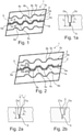
- Figures 1 to 5 each show a top view of a tread block 1 shown in a simplified form, which belongs, for example, to a tread block row running in the circumferential direction of a tread of a pneumatic vehicle tire, which is composed in particular of tread blocks of the same or similar design.
- Tread block rows with tread blocks designed according to the invention can be arranged on the tread edge or shoulder side or in the central or middle region of the tread.
- a row of tread blocks, located in the center portion of the tread, is usually lateral to those extending circumferentially of the tread Circumferential grooves, limited.
- tread blocks in a tread block row running on the shoulder side are usually delimited on the inside of the tread by grooves, which are also usually circumferential grooves or sections of circumferential grooves, but can also be groove sections of oblique grooves and the like running in the direction of the center of the tread.
- Profile blocks 1 immediately following one another in the circumferential direction are usually separated from one another by a transverse groove.
- the tread blocks 1 thus have tread block edges 1a, which are assigned to the circumferential direction of the tread and tread block edges 1b, which are assigned to the axial direction of the tread and preferably extend at an angle of ⁇ 45° to the axial direction.
- the in the Figures 1 to 5 profile blocks 1 shown are each traversed in their middle region by a special transverse groove 2 and between this and the profile block edges 1b by a respective incision 3.
- the transverse groove 2 and the incisions 3 extend parallel or substantially parallel to the tread block edges 1b.
- Both the transverse groove 2 and the incisions 3 are composed of sections 4a, 4b, 4c - transverse groove 2 - running at an angle to one another - and sections 3a, 3b and 3c - incision 3 - as will be described in more detail below, wherein in the in Figures 1 to 5 shown embodiments, the sections 4b, 4c and the sections 3b, 3c run in a trapezoidal shape, as will also be described in more detail.
- the sections 4a, 3a are end sections which are oriented parallel or substantially parallel to the tread block edges 1b.
- the transverse groove 2 has a preferably constant width in all sections 4a, 4b, 4c, which is 2.0 mm to 5.0 mm at the tread periphery.
- the transverse grooves 2 have a depth t 1 ( 1a, 2a , Figure 3a , Figure 4a and Figure 5a ), which is at least 2.0 mm and up to 60% of the tread depth intended for the respective tire, which is the depth of the main grooves, mostly circumferential grooves, of the tread and is usually 6.5 mm to 9.0 mm for car tires .
- the depth t 1 of the transverse grooves 2 can vary over their extent in the tread block 1 in the range mentioned.
- transverse grooves 2 As is shown in particular in the associated sectional views in Fig. 1a , Figure 3a and Figure 5a show groove flanks 2a, which run in the radial direction or at a small acute angle of up to 5° to the radial direction, such that the width of the transverse grooves 2 increases towards the periphery of the tread.
- the incision 5 At the bottom or at the radially inner end of the transverse grooves 2 there is an incision 5 in the radial direction, which extends down to a depth t 2 ( 1a, 2a , Figure 3a , Figure 4a and Figure 5a ) that corresponds to the intended tread depth.
- the incision 5 provided in all of the illustrated embodiment variants has a constant width of 0.3 mm to 1.2 mm, in particular 0.4 mm to 0.9 mm, and runs over all sections 4a, 4b and 4c of the transverse grooves 2
- the incision 5 can have its minimum depth—determined from the radially inner end or from the bottom of the transverse groove 2—of 1.0 mm in places or in sections.
- transverse grooves 2 sit in the embodiment variants shown, except for end portions 4a, which are parallel or substantially parallel to the Profile block edges 1b run together from sections 4b, 4c, which together form a number of adjoining, baseless, isosceles, identical or largely identical trapezoids pointing alternately in one and the other circumferential direction or alternately to one and the other profile block edge 1b form.
- Sections 4b are trapezoid leg sections which form an angle of in particular 110° to 160° with one another in plan view, sections 4c are sections connecting sections 4b.
- the incision 5 follows the course of the sections 4a, 4b and 4c of the transverse groove 2 with sections 5a, 5b, 5c running along the middle of the bottom of the transverse groove 2, namely end sections 5a, trapezium leg sections 5b and connecting sections 5c.
- the transverse groove 2 is analogous to 1 and therefore has end sections 4a, trapezoid leg sections 4b and connecting sections 4c.
- the transverse groove 2 has a groove flank 2′a running in the radial direction or at an angle of up to 5° to the radial direction and a groove flank 2′′a opposite this, which is at a larger angle ⁇ to the radial direction, this angle being 10° to 20°, in particular 15°.
- the groove flanks 2'a, 2"a change their position, as is shown in particular in the sectional views in Figures 2a and 2b demonstrate.
- the incision 5 starting from the bottom of the transverse groove 2 directly adjoins one of its incision walls to the groove flank 2"a with the greater inclination to the radial direction.
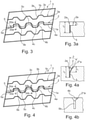
- the embodiment variant shown has the transverse groove 2 analogous to that according to FIG 1 a course with two end sections 4a and sections running trapezoidally between these end sections, ie trapezoidal leg sections 4b and connecting sections 4c.
- the incision sections 5a and 5c each connect with an incision wall to the groove flank 2a, which is longer in plan view, so that in sections 4c the incision section 5c is located further outwards in section 4c Nut flank 2a runs.
- the trapezoidal leg sections 4b of the transverse groove 2 the trapezoidal leg sections 5b of the incision 5 run between the ends of the sections 5a and 5c or the ends of sections 5c.
- the trapezoidal leg sections 5b of the incisions 5 therefore run in the relevant trapezoidal leg sections 4b of the transverse groove 2 in plan view obliquely over the bottom of the trapezoidal leg sections 4b.
- Figures 4 and 4a show a variant of the in Figures 3 and 3a illustrated embodiment.
- the transverse groove 2 has the longer groove flank 2a in plan view, which runs in the radial direction or at an angle of up to 5° to the radial direction, the opposite groove flank 2′′′a is at an angle ⁇ of 30 ° inclined to 40 ° to the radial direction, each groove flank 2a, 2′′′a merges at its radially inner end in a respective incision wall of the respective section 5a, 5c of the incision 5.
- the groove flanks 2 IV a are triangular surfaces oriented at a constant angle to the radial direction, which have their smallest, zero radial extent at the corner point of the groove flank 2a of a section 4c or 4a, and their greatest radial extent at the corner interface to the groove flank 2′′′a of a section 4c or 4a.
- the radially outer edges of the incision walls of the incision section 5b therefore run at a corresponding incline to the radial direction.
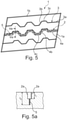
- the transverse groove 2 to analog 1 executed and running end sections 4a, trapezoid leg sections 4b and connecting sections 4c.
- the incision 5 runs in plan view in a wave form with a wavelength that corresponds at least to the extension length of each section 4a, 4b, 4c and with an amplitude that is at least 25% of the width of the bottom of the transverse groove 2.
- incisions 3 are formed in the profile block 1 between the transverse groove 2 and the profile block edge 1a, in the embodiments shown in each case an incision 3, these incisions 3 running analogously to the transverse groove 2 in a trapezoidal manner.
- more than one incision 3 be provided.
- These incisions 3 have a width which, like the incisions 5, is 0.3 mm to 1.2 mm, in particular 0.4 mm to 0.9 mm.
- the depth of the incisions 3 can at least partially correspond to the intended profile depth; the incisions 3 are usually made at different or varying depths over their extent or course. Their minimum depth is 2.0 mm.
- micro-incisions can be provided in the tread block 1 in a manner not shown, incisions that have a width of ⁇ 0.4 mm, in particular 0.2 mm to 0.3 mm, and between the incisions 3 and the transverse groove 2 or between the incisions 3 and the profile block edges 1b can be provided.
- the transverse groove 2 can also take on the function of a winter TWI (Tread Wear Indicator) if it is made so deep that the incision follows the remaining tread depth prescribed for winter tires.
- TWI Read Wear Indicator
- the transverse groove in the tread block can run along a zigzag shape or wave form, as can the incision adjoining the bottom and other incisions and micro-incisions formed in the tread block.
Landscapes
- Engineering & Computer Science (AREA)
- Mechanical Engineering (AREA)
- Tires In General (AREA)
Description
- Die Erfindung betrifft einen Fahrzeugluftreifen mit einem Laufstreifen mit zumindest einer Profilrippe oder zumindest einer Profilblöcke aufweisenden oder profilblockartig strukturierten Profilblockreihe sowie mit in der vorgesehen Profiltiefe ausgeführten Rillen, wobei zumindest eine Profilrippe bzw. die Profilblöcke in einer Blockreihe mit unter einem Winkel ≤ 45° zur axialen Richtung verlaufenden Quernuten, welche an der Laufstreifenperipherie eine Breite von 2,0 mm bis 5,0 mm und eine Tiefe von höchstens 60 % der Profiltiefe aufweisen, versehen ist bzw. sind, wobei sich jede Quernut aus Abschnitten zusammensetzt, die zueinander abgewinkelt verlaufen, wobei über die Erstreckung der Quernut an ihrem Boden bzw. ihrem radial inneren Ende ein Einschnitt anschließt, welcher eine Breite von 0,3 mm bis 1,2 mm aufweist und in radialer Richtung bis in eine Tiefe reicht, die höchstens der Profiltiefe entspricht, wobei der Einschnitt dem Verlauf der abgewinkelten Abschnitte der Quernut folgt.
- Ein derartiger Fahrzeugluftreifen ist beispielsweise aus der
JP 2012 153 157 A - Aus der
JP 2000 158 916 A - In der
EP 2 965 925 A1 ist ferner ein Fahrzeugluftreifen mit einem Laufstreifen offenbart, welcher, wie es allgemein bekannt und üblich ist, gemäß einem Verfahren der Pitchlängenvariation geräuschoptimiert ist und schulterseitig Profilblockreihen aufweist, deren Profilblöcke infolge der Pitchlängenvariation größere und kleinere Umfangslängen aufweisen. In den Schulterblöcken, die in den Pitches mit der größten Umfangslänge verlaufen, ist jeweils eine zusätzliche, gerade verlaufende Quernut ausgebildet, die den Schulterblock im Verhältnis 1:1 bis 2:3 in zwei Schulterblockteile gliedert, wobei in den Schulterblöcken, die in den Pitches mit der kleinsten Umfangslänge verlaufen, keine zusätzliche Quernut vorgesehen ist. Die Breite der zusätzlichen Quernuten beträgt 1,0 mm bis 3,0 mm, ihre Tiefe 50 % bis 100 % der Tiefe der zwischen den Schulterblöcken verlaufenden Querrillen. Durch die Zweiteilung der Schulterblöcke in den Pitches mit größerer Umfangslänge werden die Umfangssteifigkeit und die Quersteifigkeit der Schulterblöcke insgesamt über den Laufstreifenumfang gleichmäßiger. Dieser Effekt wirkt sich vor allem positiv auf den Laufstreifenabrieb aus. Aus derDE 10 2008 037 563 A1 ist ein Fahrzeugluftreifen bekannt, dessen Laufstreifen durch Umfangsrillen in in Umfangsrichtung umlaufende Profilelemente, wie Profilblockreihen oder Profilrippen gegliedert ist, wobei Profilelemente vorgesehen sind, welche mit in axialer Richtung und parallel zueinander verlaufenden Einschnitten mit einer Breite von 0,4 mm bis 0,8 mm versehen sind. Diese Einschnitte wechseln mit breiteren Einschnitten, die eine Breite von 1,0 mm bis 4,0 mm aufweisen, ab, wobei jedem breiten Einschnitt zumindest ein schmaler Einschnitt benachbart ist. Sämtliche Einschnitte reichen zumindest abschnittsweise bis in eine Tiefe, die geringer ist als die Profiltiefe. Dieser Fahrzeugluftreifen ist ein für den Wintereinsatz besonders geeigneter Reifen, wobei die breiten Einschnitte innerhalb der Profilelemente zusätzliche Kanten zur Verfügung stellen, die analog zu Blockkanten einen Fräseffekt in Schnee bewirken. Die breiten Einschnitte können sich auch gut mit Schnee auffüllen und derart die Schnee-Schnee-Reibung verbessern. Diese bekannten, breiteren Einschnitte sowie auch die aus derEP 2 965 925 A1 bekannten Quernuten verlaufen gerade und neigen auf Untergründen bzw. Straßen, auf welchen Bruchsteinsplit aufgestreut ist, zum Einfangen der kleineren Steine des Splits. Diese eingefangenen Steine verursachen diverse Probleme, unter anderem das sogenannte stone drilling, welches mit einer strukturellen Beschädigung des Reifenunterbaus einhergehen kann, ferner einen unregelmäßigen Abrieb durch Verformung der Profilelemente und Vibrationen durch Umwucht des Reifens. Darüber hinaus besteht die Gefahr, dass diese Steinchen, wenn sie bei höheren Fahrgeschwindigkeiten aus dem Laufstreifen herausgeschleudert werden, Steinschäden, etwa Lackschäden und Schäden in Windschutzscheiben, in nachfahrenden Fahrzeugen verursachen. - Der Erfindung liegt die Aufgabe zugrunde, bei einem Fahrzeugluftreifen der eingangs genannten Art die Brems- und Traktionseigenschaften auf schneeigem Untergrund, insbesondere den bereits erwähnten Fräseffekt, weiter zu verbessern und das Phänomen des Einfangens von Streusplitteilchen deutlich zu reduzieren.
- Gelöst wird die gestellte Aufgabe erfindungsgemäß durch einen Luftreifen nach Anspruch 1.
- Durch die Ausführung der Quernut mit zueinander abgewinkelt verlaufenden Abschnitten wird der Effekt des Einfangens der kleinen Partikel von Bruchsteinsplit deutlich reduziert da diese Partikel in die Abschnitte weniger leicht eindringen als in eine gradlinig verlaufende Quernut. Darüber hinaus bewirkt die Ausführung der Quernuten mit zueinander abgewinkelt verlaufenden Abschnitten verbesserte Bremseigenschaften auf Schnee durch Erhöhung der Effektivität des Fräseffektes, ferner eine Verbesserung der Traktionseigenschaften auf Schnee durch das gegenüber gerade verlaufenden Quernuten grössere Volumen der Quernuten, wodurch auch die Schnee-Schnee-Reibung verbessert wird. Der am Boden bzw. radial inneren Ende der Quernut anschliessende Einschnitt bewirkt unter Brems-und Traktionsbelastungen Abstützeffekte, die das Verklemmen von Steinchen zusätzlich behindern und die Seitenführung auf Schnee vorteilhaft beeinflussen.
- Durch die getroffenen Maßnahmen lassen sich ferner besondere Abstützeffekte erzielen. Bei einer bevorzugten Ausführungsform der Erfindung setzt sich der Einschnitt aus zueinander abgewinkelt verlaufenden Abschnitten zusammen, die dem Verlauf der abgewinkelten Abschnitte der Quernut folgen. Diese Ausführung begünstigt unter Brems-und Traktionsbelastungen eine gegenseitige Abstützung der Einschnittwände in den einzelnen Abschnitten des Einschnittes.
- Gemäß einer weiteren bevorzugten Ausführung weist die Quernut, insbesondere in sämtlichen Abschnitten, Nutflanken auf, die in radialer Richtung oder unter einem Winkel, welcher bis zu 5° von der radialen Richtung abweicht, verlaufen. Solche Quernuten besitzen daher in ihrer radialen Erstreckung eine konstante oder weitgehend konstante Breite und daher ein für die Schnee-Schnee-Reibung vorteilhaftes Aufnahmevolumen für Schnee.
- Die Art der Abwinkelung der Abschnitte der Quernut und der Einschnitte kann auf unterschiedliche Weise erfolgen. Besonders vorteilhaft zur Erzielung der oben erwähnten Effekte ist es, wenn die Abschnitte der Quernut, gegebenenfalls bis auf ihre Endabschnitte, zickzack- oder wellenförmig verlaufen, ferner, wenn die Abschnitte der Quernut, ebenfalls gegebenenfalls bis auf ihre Endabschnitte, trapezförmig verlaufen.
- Die erwähnte Trapezform ist besonders vorteilhaft für eine Optimierung der Effektivität des oben erwähnten Fräseffektes, ferner eine Optimierung der Traktionseigenschaften auf Schnee sowie, je nach Ausgestaltung, auch dafür, ein Verklemmen von Steinchen zu verhindern.
- Bei einer bevorzugten, diesbezüglich vorteilhaften Ausführung weisen die trapezförmig verlaufenden Abschnitte Trapez-Schenkelabschnitte und diese verbindende Abschnitte auf, welche in Draufsicht eine Anzahl von aneinander anschließenden, abwechselnd zur einen und zur anderen Umfangsrichtung weisenden, basislosen, vorzugsweise gleichschenkeligen Trapezen bilden, wobei die Trapez-Schenkelabschnitte und die diese verbindenden Abschnitte in Draufsicht eine längere und eine kürzere Nutflanke aufweisen.
- Die Anordnung der Einschnitte bzw. der Einschnittabschnitte am Boden bzw. am radial inneren Ende der einzelnen Abschnitte der Quernut kann ebenfalls auf unterschiedliche Weise und auf für die oben genannten Effekte besonders vorteilhafte Weise erfolgen.
- Bei einer diesbezüglich besonders bevorzugten Ausführung verlaufen die Nutflanken der Quernut in sämtlichen Abschnitten in radialer Richtung oder unter einem Winkel von bis zu 5° zur radialen Richtung, wobei in den verbindenden Abschnitten der Quernut die Einschnittabschnitte jeweils mit einer Einschnittwand an die in Draufsicht längere Nutflanke anschließen und wobei in den Trapez -Schenkelabschnitten der Quernut die Abschnitte des Einschnittes die Enden der Abschnitte des Einschnittes in den verbindenden Abschnitten miteinander verbinden.
- Bei einer weiteren, besonders bevorzugten Ausführung der Anordnung der Einschnittabschnitte innerhalb der Quernutabschnitte verläuft in den die Trapez-Schenkelabschnitte verbindenden Abschnitten der Quernut die in Draufsicht längere Nutflanke in radialer Richtung oder unter einem Winkel von bis zu 5° zur radialen Richtung, wobei die dieser gegenüberliegende Nutflanke unter einem Winkel von 10° bis 20° zur radialen Richtung verläuft, wobei in den aufeinanderfolgenden Abschnitten der Quernut die Position der Nutflanken abwechselt und der vom Boden der Quernut ausgehende Einschnitt mit einer Einschnittwand jeweils an jene Nutflanke anschließt, welche unter dem Winkel von 10° bis 30° zur radialen Richtung verläuft.
- Bei einer weiteren, besonders vorteilhaften und vor allem ein Einfangen von Steinchen besonders effektiv verhindernden Ausführungsform bzw. Ausgestaltung verläuft in den verbindenden Abschnitten die in Draufsicht längere Nutflanke in radialer Richtung oder unter einem Winkel von bis zu 5° zur radialen Richtung und die gegenüberliegende Nutflanke unter einem Winkel von 30° bis 40° zur radialen Richtung, wobei jede dieser Nutflanken an ihrem radial inneren Ende in je eine Einschnittwand des betreffenden Abschnittes des Einschnittes übergeht und wobei in den Trapez -Schenkelabschnitten die Nutflanken dreieckige, unter einem konstanten Winkel zur radialen Richtung orientierte Flächen sind, welche ihre geringste, Null betragende radiale Erstreckung jeweils beim Eckpunkt zu der in radialer Richtung verlaufenden Nutflanke eines verbindenden Abschnittes und ihre größte radiale Erstreckung bei der Eckschnittstelle zur Nutflanke eines verbindenden Abschnittes aufweisen.
- Weitere Merkmale, Vorteile und Einzelheiten der Erfindung werden nun anhand der schematischen Zeichnung, die Ausführungsbeispiele darstellt, näher beschrieben. Dabei zeigen
-
Fig. 1 eine vergrößerte Draufsicht auf einen Profilblock eines Laufstreifens eines Fahrzeugluftreifens mit einer nicht erfindungsgemäßen Ausführungsvariante, -
Fig. 1a eine Schnittdarstellung entlang der Linie Ia-Ia derFig. 1 , -
Fig. 2 eine vergrößerte Draufsicht auf einen Profilblock mit einer Ausführungsvariante der Erfindung, -
Fig. 2a eine Schnittdarstellung entlang der Linie IIa-IIa derFig. 2 und -
Fig. 2b eine Schnittdarstellung entlang der Linie IIb-IIb derFig. 2 , -
Fig. 3 eine vergrößerte Draufsicht auf einen Profilblock mit einer weiteren Ausführungsvariante der Erfindung, -
Fig. 3a eine Schnittdarstellung entlang der Linie IIIa-IIIa derFig. 3 , -
Fig. 4 eine Draufsicht auf einen Profilblock mit einer weiteren Ausführungsvariante der Erfindung, -
Fig. 4a eine Schnittdarstellung entlang der Linie IVa-IVa derFig. 4 , -
Fig. 4b eine Schnittdarstellung entlang der Linie IVb-IVb derFig. 4 -
Fig. 5 eine Draufsicht auf einen Profilblock mit einer nicht erfindungsgemäßen Ausführungsvariante und -
Fig. 5a eine Schnittdarstellung entlang der Linie Va-Va derFig. 5 . - Fahrzeugluftreifen gemäß der Erfindung sind für den Einsatz unter winterlichen Fahrbedingungen, insbesondere auf Schnee oder Eis, besonders gut geeignet und sind Reifen in Radialbauart, vorzugsweise für Personenkraftwagen, Vans oder Light Trucks.
-
Fig. 1 bis Fig. 5 zeigen jeweils eine Draufsicht auf einen in einer vereinfachten Gestalt dargestellten Profilblock 1, der beispielsweise zu einer in Umfangsrichtung eines Laufstreifens eines Fahrzeugluftreifens umlaufenden Profilblockreihe gehört, die sich insbesondere aus gleich oder gleichartig gestalteten Profilblöcken zusammensetzt. Profilblockreihen mit erfindungsgemäß gestalteten Profilblöcken können laufstreifenrand- bzw. schulterseitig oder im zentralen bzw. mittleren Bereich des Laufstreifens angeordnet sein. Eine Profilblockreihe, die im mittleren Bereich des Laufstreifens angeordnet ist, ist üblicherweise seitlich von in Umfangsrichtung des Laufstreifens verlaufenden Umfangsrillen, begrenzt. Die Profilblöcke in einer schulterseitig verlaufenden Profilblockreihe sind üblicherweise laufstreifeninnenseitig von Rillen begrenzt, die ebenfalls meist Umfangsrillen oder Abschnitte von Umfangsrillen sind aber auch Rillenabschnitte von in Richtung Laufstreifenmitte verlaufenden Schrägrillen und dergleichen sein können. In Umfangsrichtung unmittelbar aufeinanderfolgende Profilblöcke 1 sind voneinander üblicherweise durch je eine Querrille getrennt. Die Profilblöcke 1 weisen somit Profilblockkanten 1a auf, die der Umfangsrichtung des Laufstreifens zugeordnet sind und Profilblockkanten 1b, die der axialen Richtung des Laufstreifens zugeordnet sind und sich vorzugsweise unter einem Winkel ≤ 45° zur axialen Richtung erstrecken. - Die in den
Figuren 1 bis 5 dargestellten Profilblöcke 1 sind jeweils in ihrem mittleren Bereich von einer speziellen Quernut 2 und zwischen dieser und den Profilblockkanten 1b von je einem Einschnitt 3 durchquert. Bei den gezeigten Ausführungen erstrecken sich die Quernut 2 und die Einschnitte 3 parallel oder im Wesentlichen parallel zu den Profilblockkanten 1b. Sowohl die Quernut 2 als auch die Einschnitte 3 setzen sich aus zueinander abgewinkelt verlaufenden Abschnitten 4a, 4b, 4c - Quernut 2 - und Abschnitten 3a, 3b und 3c - Einschnitt 3 - wie noch näher beschrieben wird, zusammen, wobei in den inFig. 1 bis 5 gezeigten Ausführungen die Abschnitte 4b, 4c sowie die Abschnitte 3b, 3c in Trapezform verlaufen, wie ebenfalls noch näher beschrieben wird. Die Abschnitte 4a, 3a sind Endabschnitte, die parallel oder im Wesentlichen parallel zu den Profilblockkanten 1b orientiert sind. - Die Quernut 2 weist in sämtlichen Abschnitten 4a, 4b, 4c eine vorzugsweise konstante Breite auf, welche an der Laufstreifenperipherie 2,0 mm bis 5,0 mm beträgt. Die Quernuten 2 besitzen eine Tiefe t1 (
Fig. 1a, Fig. 2a ,Fig. 3a ,Fig. 4a undFig. 5a ), die zumindest 2,0 mm und bis zu 60 % der für den jeweiligen Reifen vorgesehenen Profiltiefe beträgt, welche die Tiefe der Hauptrillen, meist Umfangsrillen, des Laufstreifens ist und bei PKW-Reifen üblicherweise 6,5 mm bis 9,0 mm beträgt. Die Tiefe t1 der Quernuten 2 kann über ihre Erstreckung im Profilblock 1 im erwähnten Bereich variieren. Bei den inFig. 1 ,Fig. 3 undFig. 5 gezeigten Ausführungen weisen die Quernuten 2, wie es insbesondere die zugehörigen Schnittdarstellungen inFig. 1a ,Fig. 3a undFig. 5a zeigen, Nutflanken 2a auf, welche in radialer Richtung oder unter einem kleinen spitzen Winkel von bis zu 5° zur radialen Richtung verlaufen, derart, dass die Breite der Quernuten 2 Richtung Laufstreifenperipherie größer wird. - Am Boden bzw. am radial inneren Ende der Quernuten 2 schließt in radialer Richtung jeweils ein Einschnitt 5 an, welcher bis in eine Tiefe t2 (
Fig. 1a, Fig. 2a ,Fig. 3a ,Fig. 4a undFig. 5a ) reichen kann, die der vorgesehenen Profiltiefe entspricht. Der bei sämtlichen dargestellten Ausführungsvarianten vorgesehene Einschnitt 5 weist eine insbesondere konstante Breite von 0,3 mm bis 1,2 mm, insbesondere von 0,4 mm bis 0,9 mm, auf und verläuft über sämtliche Abschnitte 4a, 4b und 4c der Quernuten 2. Der Einschnitt 5 kann stellen- oder abschnittsweise seine Mindesttiefe - ermittelt vom radial inneren Ende bzw. vom Boden der Quernut 2 - von 1,0 mm aufweisen. - Wie bereits erwähnt, setzen sich die Quernuten 2 bei den gezeigten Ausführungsvarianten, bis auf Endabschnitte 4a, die parallel oder im Wesentlichen parallel zu den Profilblockkanten 1b verlaufen, aus Abschnitten 4b, 4c zusammen, die gemeinsam eine Anzahl von aneinander anschließenden, abwechselnd in die eine und in die andere Umfangsrichtung bzw. abwechselnd zur einen und zur anderen Profilblockkante 1b weisenden, basislosen, gleichschenkeligen, übereinstimmend oder weitgehend übereinstimmend ausgeführten Trapezen bilden. Die Abschnitte 4b sind Trapezschenkel-Abschnitte, welche in Draufsicht miteinander einen Winkel von insbesondere 110° bis 160° einschließen, die Abschnitte 4c sind die Abschnitte 4b verbindende Abschnitte.
- Bei der in
Fig. 1 und 1a dargestellten Variante folgt der Einschnitt 5 dem Verlauf der Abschnitte 4a, 4b und 4c der Quernut 2 mit entlang der Mitte des Bodens der Quernut 2 verlaufenden Abschnitten 5a, 5b, 5c, nämlich Endabschnitten 5a, Trapezschenkel-Abschnitten 5b und verbindenden Abschnitten 5c. - Bei der in
Fig. 2 und 2a gezeigten Ausführung verläuft die Quernut 2 analog zuFig. 1 und weist daher Endabschnitte 4a, Trapezschenkel-Abschnitte 4b und verbindende Abschnitte 4c auf. In jedem Abschnitt 4a, 4b und 4c weist die Quernut 2 einen in radialer Richtung oder unter einem Winkel von bis zu 5° zur radialen Richtung verlaufende Nutflanke 2'a und eine dieser gegenüberliegende Nutflanke 2"a auf, welche unter einem größeren Winkel α zur radialen Richtung geneigt ist, wobei dieser Winkel 10° bis 20°, insbesondere 15°, beträgt. In den einzelnen aufeinander folgenden Abschnitte 4a, 4b, 4c wechseln jeweils die Nutflanken 2'a, 2"a ihre Position, wie es insbesondere die Schnittdarstellungen inFig. 2a und Fig. 2b zeigen. Der vom Boden der Quernut 2 ausgehende Einschnitt 5 schließt jeweils unmittelbar mit einer seiner Einschnittwände an die Nutflanke 2"a mit der größeren Neigung zur radialen Richtung an. - Auch bei der in
Fig. 3 und Fig. 3a gezeigten Ausführungsvariante weist die Quernut 2 analog zu jener gemäßFig. 1 einen Verlauf mit zwei Endabschnitten 4a und zwischen diesen Endabschnitten trapezförmig verlaufenden Abschnitten, also Trapezschenkel-Abschnitten 4b und verbindenden Abschnitten 4c, auf. In den Endabschnitten 4a und den verbindenden Abschnitten 4c schließen die Einschnittabschnitte 5a und 5c jeweils mit einer Einschnittwand an die in Draufsicht längere Nutflanke 2a an, sodass in den Abschnitten 4c der Einschnittabschnitt 5c jeweils bei der im Abschnitt 4c weiter außen befindlichen Nutflanke 2a verläuft. In den Trapezschenkel-Abschnitten 4b der Quernut 2 verlaufen die Trapezschenkel-Abschnitte 5b des Einschnittes 5 zwischen den Enden der Abschnitte 5a und 5c bzw. den Enden von Abschnitten 5c. Die Trapezschenkel-Abschnitte 5b der Einschnitte 5 verlaufen daher in den betreffenden Trapezschenkel-Abschnitten 4b der Quernut 2 in Draufsicht schräg über den Boden der Trapezschenkel-Abschnitte 4b. -
Fig. 4 und 4a zeigen eine Variante der inFig. 3 und 3a dargestellten Ausführungsform. In den Endabschnitten 4a und den verbindenden Abschnitten 4c weist die Quernut 2 verläuft jeweils die in Draufsicht längere Nutflanke 2a in radialer Richtung oder unter einem Winkel von bis zu 5° zur radialen Richtung, die gegenüberliegende Nutflanke 2‴a ist unter einem Winkel β von 30° bis 40° zur radialen Richtung geneigt, wobei jede Nutflanke 2a, 2‴a an ihrem radial inneren Ende in je eine Einschnittwand des jeweiligen Abschnittes 5a, 5c des Einschnittes 5 übergeht. In den Trapezschenkel-Abschnitten 4b sind die Nutflanken 2IVa dreieckige, unter einem konstanten Winkel zur radialen Richtung orientierte Flächen, welche ihre geringste, Null betragende radiale Erstreckung jeweils beim Eckpunkt zur Nutflanke 2a eines Abschnittes 4c oder 4a aufweisen, ihre größte radiale Erstreckung bei der Eckschnittstelle zur Nutflanke 2‴a eines Abschnittes 4c oder 4a. Die radial äußeren Kanten der Einschnittwände des Einschnittabschnittes 5b verlaufen daher zur radialen Richtung entsprechend geneigt. - Bei der in
Fig. 5 und 5a gezeigten Ausführungsform weist die Quernut 2 analog zuFig. 1 ausgeführte und verlaufende Endabschnitte 4a, Trapezschenkel-Abschnitte 4b und verbindende Abschnitte 4c auf. Entlang des Bodens der Quernut 2 verläuft der Einschnitt 5 in Draufsicht in Wellenform mit einer Wellenlänge, die mindestens der Erstreckungslänge jedes Abschnittes 4a, 4b, 4c entspricht und mit einer Amplitude, die zumindest 25 % der Breite des Bodens der Quernut 2 beträgt. - Bei sämtlichen Ausführungsvarianten sind im Profilblock 1 zwischen der Quernut 2 und der Profilblockkante 1a weitere Einschnitte 3 ausgebildet, bei den gezeigten Ausführungen jeweils ein Einschnitt 3, wobei diese Einschnitte 3 analog zur Quernut 2 trapezförmig verlaufen. Bei weiteren, nicht dargestellten Ausführungsvarianten kann zwischen der Quernut 2 und der jeweiligen Profilblockkante 1a auch mehr als ein Einschnitt 3 vorgesehen sein. Diese Einschnitte 3 weisen eine Breite auf, die analog zu den Einschnitten 5 0,3 mm bis 1,2 mm, insbesondere 0,4 mm bis 0,9 mm, beträgt. Die Tiefe der Einschnitte 3 kann zumindest abschnittsweise der vorgesehenen Profiltiefe entsprechen, üblicherweise werden die Einschnitte 3 über ihre Erstreckung bzw. ihren Verlauf in unterschiedlichen bzw. variierenden Tiefen ausgeführt. Ihre Mindesttiefe beträgt 2,0 mm. Darüber hinaus können auf nicht dargestellte Weise auch sogenannte Mikroeinschnitte im Profilblock 1 vorgesehen sein, Einschnitte, die eine Breite < 0,4 mm, insbesondere 0,2 mm bis 0,3 mm, aufweisen und zwischen den Einschnitten 3 und der Quernut 2 oder zwischen den Einschnitten 3 und den Profilblockkanten 1b vorgesehen sein können.
- Die Quernut 2 kann ferner die Funktion eines Winter-TWI (Tread Wear Indikators) übernehmen, wenn sie derart tief ausgeführt wird, dass der Einschnitt in der für Winterreifen vorgeschriebenen Restprofiltiefe anschließt.
- Darüber hinaus kann die Quernut im Profilblock entlang einer Zick-Zack-Form oder Wellenform verlaufen, ebenso der am Boden anschließende Einschnitt sowie weitere im Profilblock ausgebildete Einschnitte und Mikroeinschnitte.
-
- 1
- Profilblock
- 1a, 1b
- Profilblockkante
- 2
- Quernut
- 2a, 2'a
- Nutflanke
- 2ʺa, 2‴a, 2IVa
- Nutflanke
- 3
- Einschnitt
- 3a, 3b, 3c
- Abschnitt
- 4a, 4b, 4c
- Abschnitt
- 5
- Einschnitt
- 5a, 5b, 5c
- Abschnitt
- α, β
- Winkel
- t1, t2
- Tiefe
Claims (9)
- Fahrzeugluftreifen mit einem Laufstreifen mit zumindest einer Profilrippe oder zumindest einer Profilblöcke (1) aufweisenden oder profilblockartig strukturierten Profilblockreihe sowie mit in der vorgesehen Profiltiefe ausgeführten Rillen, wobei zumindest eine Profilrippe bzw. die Profilblöcke in einer Blockreihe mit unter einem Winkel ≤ 45° zur axialen Richtung verlaufenden Quernuten (2), welche an der Laufstreifenperipherie eine Breite von 2,0 mm bis 5,0 mm und eine Tiefe (t1) von höchstens 60 % der Profiltiefe aufweisen, versehen ist bzw. sind,wobei sich jede Quernut (2) aus Abschnitten (4a, 4b, 4c) zusammensetzt, die zueinander abgewinkelt verlaufen, wobei über die Erstreckung der Quernut (2) an ihrem Boden bzw. ihrem radial inneren Ende ein Einschnitt (5) anschließt, welcher eine Breite von 0,3 mm bis 1,2 mm aufweist und in radialer Richtung bis in eine Tiefe (t2) reicht, die höchstens der Profiltiefe entspricht, wobei der Einschnitt (5) dem Verlauf der abgewinkelten Abschnitte (4a, 4b, 4c) der Quernut (2) folgt,dadurch gekennzeichnet,dass die Profilrippe bzw. die Profilblöcke der Blockreihe von sich im Wesentlichen parallel zueinander und parallel zu den Quernuten (2) erstreckenden Einschnitten (3) mit einer Breite von 0,3 mm bis 1,2 mm durchquert ist bzw. sind, wobei Einschnitte (3) vorgesehen sind, zwischen welchen jeweils eine der sich parallel zu den Einschnitten (3) erstreckenden Quernuten (2) vorgesehen ist,wobei der Einschnitt (5), welcher dem Verlauf der abgewinkelten Abschnitte (4a, 4b, 4c) der Quernut (2) folgt, Einschnittabschnitte (5a, 5b, 5c) aufweist, die in den aufeinanderfolgenden Abschnitten (4a, 4b, 4c) der Quernut (2) abwechselnd mit einer Einschnittwand an die eine und die andere Nutflanke (2a) der Quernut (2) anschließen.
- Fahrzeugluftreifen nach Anspruch 1, dadurch gekennzeichnet, dass sich der Einschnitt (5) aus zueinander abgewinkelt verlaufenden Abschnitten (5a, 5b, 5c) zusammensetzt, die dem Verlauf der abgewinkelten Abschnitte (4a, 4b, 4c) der Quernut (2) folgen.
- Fahrzeugluftreifen nach Anspruch 1 oder 2, dadurch gekennzeichnet, dass die Quernut (2), insbesondere in sämtlichen Abschnitten (4a, 4b, 4c), Nutflanken (2a) aufweist, die in radialer Richtung oder unter einem Winkel, welcher um bis zu 5° von der radialen Richtung abweicht, verlaufen.
- Fahrzeugluftreifen nach einem der Ansprüche 1 bis 3, dadurch gekennzeichnet, dass die Abschnitte der Quernut, gegebenenfalls bis auf ihre Endabschnitte, zickzack- oder wellenförmig verlaufen.
- Fahrzeugluftreifen nach einem der Ansprüche 1 bis 3, dadurch gekennzeichnet, dass die Abschnitte (4b, 4c) der Quernut (2), gegebenenfalls bis auf ihre Endabschnitte (4a), trapezförmig verlaufen.
- Fahrzeugluftreifen nach Anspruch 5, dadurch gekennzeichnet, dass die trapezförmig verlaufenden Abschnitte (4b, 4c) Trapezschenkel-Abschnitte (4b) und diese verbindende Abschnitte (4c) aufweisen, welche in Draufsicht eine Anzahl von aneinander anschließenden, abwechselnd zur einen und zur anderen Umfangsrichtung weisenden, basislosen, vorzugsweise gleichschenkeligen Trapezen bilden, wobei die Trapezschenkel-Abschnitte (4b) und die diese verbindenden Abschnitte (4c) in Draufsicht eine längere und eine kürzere Nutflanke aufweisen.
- Fahrzeugluftreifen nach Anspruch 5 oder 6, dadurch gekennzeichnet, dass die Nutflanken (2a) der Quernut (2) in sämtlichen Abschnitten (4a, 4b, 4c) in radialer Richtung oder unter einem Winkel von bis zu 5° zur radialen Richtung verlaufen, wobei in den verbindenden Abschnitten (4c) die Einschnittabschnitte (5c) jeweils mit einer Einschnittwand an die in Draufsicht längere Nutflanke (2a) anschließen, und wobei in den Trapezschenkel-Abschnitten (4b) der Quernut (2) die Abschnitte (5b) des Einschnittes (5) die Enden der Abschnitte (5c) des Einschnittes (5) in den verbindenden Abschnitten (4c) miteinander verbinden (Fig. 3, 3a).
- Fahrzeugluftreifen nach Anspruch 5 oder 6, dadurch gekennzeichnet, dass in den die Trapezschenkel-Abschnitte (4b) verbindenden Abschnitten (4c) der Quernut (2) die in Draufsicht längere Nutflanke (2'a) in radialer Richtung oder unter einem Winkel von bis zu 5° zur radialen Richtung verläuft, wobei die dieser gegenüberliegende Nutflanke (2‴a) unter einem Winkel (a) von 10° bis 20° zur radialen Richtung verläuft, wobei in den aufeinanderfolgenden Abschnitten (4a, 4b, 4c) der Quernut (2) die Position der Nutflanken (2'a, 2"a) abwechselt und der vom Boden der Quernut (2) ausgehende Einschnitt (5) mit einer Einschnittwand jeweils an jene Nutflanke (2"a) anschließt, welche unter dem Winkel (a) von 10° bis 20° zur radialen Richtung verläuft (Fig. 2, 2a, 2b).
- Fahrzeugluftreifen nach Anspruch 5 oder 6, dadurch gekennzeichnet, dass in den verbindenden Abschnitten (4c) die in Draufsicht längere Nutflanke (2a) in radialer Richtung oder unter einem Winkel von bis zu 5° zur radialen Richtung verläuft und die gegenüberliegende Nutflanke (2‴a) unter einem Winkel (β) von 30° bis 40° zur radialen Richtung geneigt ist, wobei jede dieser Nutflanken (2a, 2‴a) an ihrem radial inneren Ende in je eine Einschnittwand des betreffenden Abschnittes (5c) des Einschnittes (5) übergeht, und wobei in den Trapezschenkel-Abschnitten (4b) die Nutflanken (2IVa) dreieckige, unter einem konstanten Winkel zur radialen Richtung orientierte Flächen sind, welche ihre geringste, Null betragende radiale Erstreckung jeweils beim Eckpunkt zu der in radialer Richtung verlaufenden Nutflanke (2a) eines verbindenden Abschnittes (4c) und ihre größte radiale Erstreckung bei der Eckschnittstelle zur Nutflanke (2‴a) eines verbindenden Abschnittes (4c) aufweisen (Fig. 4, 4a, 4b).
Applications Claiming Priority (2)
| Application Number | Priority Date | Filing Date | Title |
|---|---|---|---|
| DE102017222513.0A DE102017222513A1 (de) | 2017-12-12 | 2017-12-12 | Fahrzeugluftreifen |
| PCT/EP2018/075872 WO2019115039A1 (de) | 2017-12-12 | 2018-09-25 | Fahrzeugluftreifen |
Publications (2)
| Publication Number | Publication Date |
|---|---|
| EP3724005A1 EP3724005A1 (de) | 2020-10-21 |
| EP3724005B1 true EP3724005B1 (de) | 2022-03-02 |
Family
ID=63762471
Family Applications (1)
| Application Number | Title | Priority Date | Filing Date |
|---|---|---|---|
| EP18782348.9A Active EP3724005B1 (de) | 2017-12-12 | 2018-09-25 | Fahrzeugluftreifen |
Country Status (3)
| Country | Link |
|---|---|
| EP (1) | EP3724005B1 (de) |
| DE (1) | DE102017222513A1 (de) |
| WO (1) | WO2019115039A1 (de) |
Families Citing this family (2)
| Publication number | Priority date | Publication date | Assignee | Title |
|---|---|---|---|---|
| JP7116710B2 (ja) * | 2019-06-14 | 2022-08-10 | 株式会社ブリヂストン | 空気入りタイヤ |
| DE102023206736A1 (de) | 2023-07-14 | 2025-01-16 | Continental Reifen Deutschland Gmbh | Fahrzeugreifen |
Family Cites Families (4)
| Publication number | Priority date | Publication date | Assignee | Title |
|---|---|---|---|---|
| JP4189980B2 (ja) * | 1998-11-27 | 2008-12-03 | 株式会社ブリヂストン | 空気入りタイヤ |
| DE102008037563A1 (de) | 2008-11-19 | 2010-05-20 | Continental Reifen Deutschland Gmbh | Fahrzeugluftreifen |
| JP6110586B2 (ja) * | 2011-01-21 | 2017-04-05 | 株式会社ブリヂストン | 空気入りタイヤ |
| DE102014213266A1 (de) | 2014-07-09 | 2016-01-14 | Continental Reifen Deutschland Gmbh | Fahrzeugluftreifen |
-
2017
- 2017-12-12 DE DE102017222513.0A patent/DE102017222513A1/de not_active Withdrawn
-
2018
- 2018-09-25 EP EP18782348.9A patent/EP3724005B1/de active Active
- 2018-09-25 WO PCT/EP2018/075872 patent/WO2019115039A1/de not_active Ceased
Also Published As
| Publication number | Publication date |
|---|---|
| EP3724005A1 (de) | 2020-10-21 |
| DE102017222513A1 (de) | 2019-06-13 |
| WO2019115039A1 (de) | 2019-06-20 |
Similar Documents
| Publication | Publication Date | Title |
|---|---|---|
| EP2222481B1 (de) | Fahrzeugluftreifen | |
| EP3888948B1 (de) | Fahrzeugluftreifen, insbesondere nutzfahrzeugreifen | |
| EP3724006B1 (de) | Nutzfahrzeugreifen | |
| DE102019213044A1 (de) | Fahrzeugluftreifen | |
| EP3421264B1 (de) | Fahrzeugluftreifen | |
| EP2773519A1 (de) | Fahrzeugluftreifen | |
| DE102008037563A1 (de) | Fahrzeugluftreifen | |
| EP3383675B1 (de) | Fahrzeugluftreifen | |
| DE202007019375U1 (de) | Fahrzeugluftreifen | |
| EP3441241B1 (de) | Fahrzeugluftreifen | |
| WO2019115039A1 (de) | Fahrzeugluftreifen | |
| DE19957914C2 (de) | Fahrzeugluftreifen | |
| EP2138329B1 (de) | Laufflächenprofil für einen Fahrzeugluftreifen | |
| EP2138327A1 (de) | Laufflächenprofil für einen Fahrzeugluftreifen | |
| EP4321350B1 (de) | Fahrzeugluftreifen | |
| EP4076995B1 (de) | Fahrzeugluftreifen | |
| DE102018206902A1 (de) | Fahrzeugluftreifen | |
| EP3300925B1 (de) | Fahrzeugluftreifen | |
| EP4003760B1 (de) | Fahrzeugluftreifen | |
| EP3717282B1 (de) | Fahrzeugluftreifen | |
| EP4140776B1 (de) | Fahrzeugluftreifen | |
| EP2138328A1 (de) | Fahrzeugluftreifen | |
| EP4342688B1 (de) | Fahrzeugluftreifen | |
| EP4342685B1 (de) | Fahrzeugluftreifen | |
| DE102006058086B4 (de) | Fahrzeugluftreifen |
Legal Events
| Date | Code | Title | Description |
|---|---|---|---|
| STAA | Information on the status of an ep patent application or granted ep patent |
Free format text: STATUS: UNKNOWN |
|
| STAA | Information on the status of an ep patent application or granted ep patent |
Free format text: STATUS: THE INTERNATIONAL PUBLICATION HAS BEEN MADE |
|
| PUAI | Public reference made under article 153(3) epc to a published international application that has entered the european phase |
Free format text: ORIGINAL CODE: 0009012 |
|
| STAA | Information on the status of an ep patent application or granted ep patent |
Free format text: STATUS: REQUEST FOR EXAMINATION WAS MADE |
|
| 17P | Request for examination filed |
Effective date: 20200713 |
|
| AK | Designated contracting states |
Kind code of ref document: A1 Designated state(s): AL AT BE BG CH CY CZ DE DK EE ES FI FR GB GR HR HU IE IS IT LI LT LU LV MC MK MT NL NO PL PT RO RS SE SI SK SM TR |
|
| AX | Request for extension of the european patent |
Extension state: BA ME |
|
| RAP1 | Party data changed (applicant data changed or rights of an application transferred) |
Owner name: CONTINENTAL REIFEN DEUTSCHLAND GMBH |
|
| DAV | Request for validation of the european patent (deleted) | ||
| DAX | Request for extension of the european patent (deleted) | ||
| GRAP | Despatch of communication of intention to grant a patent |
Free format text: ORIGINAL CODE: EPIDOSNIGR1 |
|
| STAA | Information on the status of an ep patent application or granted ep patent |
Free format text: STATUS: GRANT OF PATENT IS INTENDED |
|
| INTG | Intention to grant announced |
Effective date: 20210927 |
|
| GRAS | Grant fee paid |
Free format text: ORIGINAL CODE: EPIDOSNIGR3 |
|
| GRAA | (expected) grant |
Free format text: ORIGINAL CODE: 0009210 |
|
| STAA | Information on the status of an ep patent application or granted ep patent |
Free format text: STATUS: THE PATENT HAS BEEN GRANTED |
|
| AK | Designated contracting states |
Kind code of ref document: B1 Designated state(s): AL AT BE BG CH CY CZ DE DK EE ES FI FR GB GR HR HU IE IS IT LI LT LU LV MC MK MT NL NO PL PT RO RS SE SI SK SM TR |
|
| REG | Reference to a national code |
Ref country code: GB Ref legal event code: FG4D Free format text: NOT ENGLISH |
|
| REG | Reference to a national code |
Ref country code: CH Ref legal event code: EP Ref country code: AT Ref legal event code: REF Ref document number: 1471944 Country of ref document: AT Kind code of ref document: T Effective date: 20220315 |
|
| REG | Reference to a national code |
Ref country code: DE Ref legal event code: R096 Ref document number: 502018008959 Country of ref document: DE |
|
| REG | Reference to a national code |
Ref country code: IE Ref legal event code: FG4D Free format text: LANGUAGE OF EP DOCUMENT: GERMAN |
|
| REG | Reference to a national code |
Ref country code: NL Ref legal event code: FP |
|
| REG | Reference to a national code |
Ref country code: FI Ref legal event code: FGE |
|
| REG | Reference to a national code |
Ref country code: SE Ref legal event code: TRGR |
|
| REG | Reference to a national code |
Ref country code: LT Ref legal event code: MG9D |
|
| PG25 | Lapsed in a contracting state [announced via postgrant information from national office to epo] |
Ref country code: RS Free format text: LAPSE BECAUSE OF FAILURE TO SUBMIT A TRANSLATION OF THE DESCRIPTION OR TO PAY THE FEE WITHIN THE PRESCRIBED TIME-LIMIT Effective date: 20220302 Ref country code: NO Free format text: LAPSE BECAUSE OF FAILURE TO SUBMIT A TRANSLATION OF THE DESCRIPTION OR TO PAY THE FEE WITHIN THE PRESCRIBED TIME-LIMIT Effective date: 20220602 Ref country code: LT Free format text: LAPSE BECAUSE OF FAILURE TO SUBMIT A TRANSLATION OF THE DESCRIPTION OR TO PAY THE FEE WITHIN THE PRESCRIBED TIME-LIMIT Effective date: 20220302 Ref country code: HR Free format text: LAPSE BECAUSE OF FAILURE TO SUBMIT A TRANSLATION OF THE DESCRIPTION OR TO PAY THE FEE WITHIN THE PRESCRIBED TIME-LIMIT Effective date: 20220302 Ref country code: ES Free format text: LAPSE BECAUSE OF FAILURE TO SUBMIT A TRANSLATION OF THE DESCRIPTION OR TO PAY THE FEE WITHIN THE PRESCRIBED TIME-LIMIT Effective date: 20220302 Ref country code: BG Free format text: LAPSE BECAUSE OF FAILURE TO SUBMIT A TRANSLATION OF THE DESCRIPTION OR TO PAY THE FEE WITHIN THE PRESCRIBED TIME-LIMIT Effective date: 20220602 |
|
| PG25 | Lapsed in a contracting state [announced via postgrant information from national office to epo] |
Ref country code: PL Free format text: LAPSE BECAUSE OF FAILURE TO SUBMIT A TRANSLATION OF THE DESCRIPTION OR TO PAY THE FEE WITHIN THE PRESCRIBED TIME-LIMIT Effective date: 20220302 Ref country code: LV Free format text: LAPSE BECAUSE OF FAILURE TO SUBMIT A TRANSLATION OF THE DESCRIPTION OR TO PAY THE FEE WITHIN THE PRESCRIBED TIME-LIMIT Effective date: 20220302 Ref country code: GR Free format text: LAPSE BECAUSE OF FAILURE TO SUBMIT A TRANSLATION OF THE DESCRIPTION OR TO PAY THE FEE WITHIN THE PRESCRIBED TIME-LIMIT Effective date: 20220603 |
|
| PG25 | Lapsed in a contracting state [announced via postgrant information from national office to epo] |
Ref country code: SM Free format text: LAPSE BECAUSE OF FAILURE TO SUBMIT A TRANSLATION OF THE DESCRIPTION OR TO PAY THE FEE WITHIN THE PRESCRIBED TIME-LIMIT Effective date: 20220302 Ref country code: SK Free format text: LAPSE BECAUSE OF FAILURE TO SUBMIT A TRANSLATION OF THE DESCRIPTION OR TO PAY THE FEE WITHIN THE PRESCRIBED TIME-LIMIT Effective date: 20220302 Ref country code: RO Free format text: LAPSE BECAUSE OF FAILURE TO SUBMIT A TRANSLATION OF THE DESCRIPTION OR TO PAY THE FEE WITHIN THE PRESCRIBED TIME-LIMIT Effective date: 20220302 Ref country code: PT Free format text: LAPSE BECAUSE OF FAILURE TO SUBMIT A TRANSLATION OF THE DESCRIPTION OR TO PAY THE FEE WITHIN THE PRESCRIBED TIME-LIMIT Effective date: 20220704 Ref country code: EE Free format text: LAPSE BECAUSE OF FAILURE TO SUBMIT A TRANSLATION OF THE DESCRIPTION OR TO PAY THE FEE WITHIN THE PRESCRIBED TIME-LIMIT Effective date: 20220302 Ref country code: CZ Free format text: LAPSE BECAUSE OF FAILURE TO SUBMIT A TRANSLATION OF THE DESCRIPTION OR TO PAY THE FEE WITHIN THE PRESCRIBED TIME-LIMIT Effective date: 20220302 |
|
| PG25 | Lapsed in a contracting state [announced via postgrant information from national office to epo] |
Ref country code: IS Free format text: LAPSE BECAUSE OF FAILURE TO SUBMIT A TRANSLATION OF THE DESCRIPTION OR TO PAY THE FEE WITHIN THE PRESCRIBED TIME-LIMIT Effective date: 20220702 Ref country code: AL Free format text: LAPSE BECAUSE OF FAILURE TO SUBMIT A TRANSLATION OF THE DESCRIPTION OR TO PAY THE FEE WITHIN THE PRESCRIBED TIME-LIMIT Effective date: 20220302 |
|
| REG | Reference to a national code |
Ref country code: DE Ref legal event code: R097 Ref document number: 502018008959 Country of ref document: DE |
|
| PLBE | No opposition filed within time limit |
Free format text: ORIGINAL CODE: 0009261 |
|
| STAA | Information on the status of an ep patent application or granted ep patent |
Free format text: STATUS: NO OPPOSITION FILED WITHIN TIME LIMIT |
|
| PG25 | Lapsed in a contracting state [announced via postgrant information from national office to epo] |
Ref country code: DK Free format text: LAPSE BECAUSE OF FAILURE TO SUBMIT A TRANSLATION OF THE DESCRIPTION OR TO PAY THE FEE WITHIN THE PRESCRIBED TIME-LIMIT Effective date: 20220302 |
|
| 26N | No opposition filed |
Effective date: 20221205 |
|
| PG25 | Lapsed in a contracting state [announced via postgrant information from national office to epo] |
Ref country code: SI Free format text: LAPSE BECAUSE OF FAILURE TO SUBMIT A TRANSLATION OF THE DESCRIPTION OR TO PAY THE FEE WITHIN THE PRESCRIBED TIME-LIMIT Effective date: 20220302 |
|
| PG25 | Lapsed in a contracting state [announced via postgrant information from national office to epo] |
Ref country code: MC Free format text: LAPSE BECAUSE OF FAILURE TO SUBMIT A TRANSLATION OF THE DESCRIPTION OR TO PAY THE FEE WITHIN THE PRESCRIBED TIME-LIMIT Effective date: 20220302 |
|
| REG | Reference to a national code |
Ref country code: CH Ref legal event code: PL |
|
| GBPC | Gb: european patent ceased through non-payment of renewal fee |
Effective date: 20220925 |
|
| REG | Reference to a national code |
Ref country code: BE Ref legal event code: MM Effective date: 20220930 |
|
| PG25 | Lapsed in a contracting state [announced via postgrant information from national office to epo] |
Ref country code: LU Free format text: LAPSE BECAUSE OF NON-PAYMENT OF DUE FEES Effective date: 20220925 |
|
| P01 | Opt-out of the competence of the unified patent court (upc) registered |
Effective date: 20230602 |
|
| PG25 | Lapsed in a contracting state [announced via postgrant information from national office to epo] |
Ref country code: LI Free format text: LAPSE BECAUSE OF NON-PAYMENT OF DUE FEES Effective date: 20220930 Ref country code: IT Free format text: LAPSE BECAUSE OF FAILURE TO SUBMIT A TRANSLATION OF THE DESCRIPTION OR TO PAY THE FEE WITHIN THE PRESCRIBED TIME-LIMIT Effective date: 20220302 Ref country code: IE Free format text: LAPSE BECAUSE OF NON-PAYMENT OF DUE FEES Effective date: 20220925 Ref country code: FR Free format text: LAPSE BECAUSE OF NON-PAYMENT OF DUE FEES Effective date: 20220930 Ref country code: CH Free format text: LAPSE BECAUSE OF NON-PAYMENT OF DUE FEES Effective date: 20220930 |
|
| PG25 | Lapsed in a contracting state [announced via postgrant information from national office to epo] |
Ref country code: BE Free format text: LAPSE BECAUSE OF NON-PAYMENT OF DUE FEES Effective date: 20220930 |
|
| PG25 | Lapsed in a contracting state [announced via postgrant information from national office to epo] |
Ref country code: GB Free format text: LAPSE BECAUSE OF NON-PAYMENT OF DUE FEES Effective date: 20220925 |
|
| REG | Reference to a national code |
Ref country code: DE Ref legal event code: R081 Ref document number: 502018008959 Country of ref document: DE Owner name: CONTINENTAL REIFEN DEUTSCHLAND GMBH, DE Free format text: FORMER OWNER: CONTINENTAL REIFEN DEUTSCHLAND GMBH, 30165 HANNOVER, DE |
|
| PG25 | Lapsed in a contracting state [announced via postgrant information from national office to epo] |
Ref country code: CY Free format text: LAPSE BECAUSE OF FAILURE TO SUBMIT A TRANSLATION OF THE DESCRIPTION OR TO PAY THE FEE WITHIN THE PRESCRIBED TIME-LIMIT Effective date: 20220302 |
|
| PG25 | Lapsed in a contracting state [announced via postgrant information from national office to epo] |
Ref country code: MK Free format text: LAPSE BECAUSE OF FAILURE TO SUBMIT A TRANSLATION OF THE DESCRIPTION OR TO PAY THE FEE WITHIN THE PRESCRIBED TIME-LIMIT Effective date: 20220302 Ref country code: HU Free format text: LAPSE BECAUSE OF FAILURE TO SUBMIT A TRANSLATION OF THE DESCRIPTION OR TO PAY THE FEE WITHIN THE PRESCRIBED TIME-LIMIT; INVALID AB INITIO Effective date: 20180925 |
|
| PG25 | Lapsed in a contracting state [announced via postgrant information from national office to epo] |
Ref country code: TR Free format text: LAPSE BECAUSE OF FAILURE TO SUBMIT A TRANSLATION OF THE DESCRIPTION OR TO PAY THE FEE WITHIN THE PRESCRIBED TIME-LIMIT Effective date: 20220302 |
|
| PG25 | Lapsed in a contracting state [announced via postgrant information from national office to epo] |
Ref country code: MT Free format text: LAPSE BECAUSE OF FAILURE TO SUBMIT A TRANSLATION OF THE DESCRIPTION OR TO PAY THE FEE WITHIN THE PRESCRIBED TIME-LIMIT Effective date: 20220302 |
|
| PGFP | Annual fee paid to national office [announced via postgrant information from national office to epo] |
Ref country code: FI Payment date: 20240918 Year of fee payment: 7 |
|
| PGFP | Annual fee paid to national office [announced via postgrant information from national office to epo] |
Ref country code: NL Payment date: 20240918 Year of fee payment: 7 |
|
| PGFP | Annual fee paid to national office [announced via postgrant information from national office to epo] |
Ref country code: SE Payment date: 20240919 Year of fee payment: 7 |
|
| REG | Reference to a national code |
Ref country code: AT Ref legal event code: MM01 Ref document number: 1471944 Country of ref document: AT Kind code of ref document: T Effective date: 20230925 |
|
| PG25 | Lapsed in a contracting state [announced via postgrant information from national office to epo] |
Ref country code: AT Free format text: LAPSE BECAUSE OF NON-PAYMENT OF DUE FEES Effective date: 20230925 |
|
| PG25 | Lapsed in a contracting state [announced via postgrant information from national office to epo] |
Ref country code: AT Free format text: LAPSE BECAUSE OF NON-PAYMENT OF DUE FEES Effective date: 20230925 |
|
| PGFP | Annual fee paid to national office [announced via postgrant information from national office to epo] |
Ref country code: DE Payment date: 20250930 Year of fee payment: 8 |
|
| PG25 | Lapsed in a contracting state [announced via postgrant information from national office to epo] |
Ref country code: FI Free format text: LAPSE BECAUSE OF NON-PAYMENT OF DUE FEES Effective date: 20250925 |
|
| PGFP | Annual fee paid to national office [announced via postgrant information from national office to epo] |
Ref country code: AT Payment date: 20260410 Year of fee payment: 5 |
|
| REG | Reference to a national code |
Ref country code: NL Ref legal event code: MM Effective date: 20251001 |