EP3723985B1 - Wetting apparatus - Google Patents
Wetting apparatus Download PDFInfo
- Publication number
- EP3723985B1 EP3723985B1 EP17934496.5A EP17934496A EP3723985B1 EP 3723985 B1 EP3723985 B1 EP 3723985B1 EP 17934496 A EP17934496 A EP 17934496A EP 3723985 B1 EP3723985 B1 EP 3723985B1
- Authority
- EP
- European Patent Office
- Prior art keywords
- slit
- boundary
- liquid agent
- flow
- lip
- Prior art date
- Legal status (The legal status is an assumption and is not a legal conclusion. Google has not performed a legal analysis and makes no representation as to the accuracy of the status listed.)
- Not-in-force
Links
- 238000009736 wetting Methods 0.000 title claims description 12
- 239000007788 liquid Substances 0.000 claims description 91
- 238000012546 transfer Methods 0.000 claims description 53
- 230000015572 biosynthetic process Effects 0.000 claims description 11
- 238000000034 method Methods 0.000 claims description 8
- 238000013508 migration Methods 0.000 claims description 7
- 230000005012 migration Effects 0.000 claims description 7
- 239000011800 void material Substances 0.000 claims description 7
- 230000014759 maintenance of location Effects 0.000 claims description 2
- 239000003795 chemical substances by application Substances 0.000 description 68
- 238000005755 formation reaction Methods 0.000 description 10
- 238000000576 coating method Methods 0.000 description 4
- 239000000463 material Substances 0.000 description 4
- 230000037361 pathway Effects 0.000 description 4
- 239000011248 coating agent Substances 0.000 description 3
- 238000005192 partition Methods 0.000 description 3
- 229910000639 Spring steel Inorganic materials 0.000 description 2
- 238000010586 diagram Methods 0.000 description 2
- 238000003780 insertion Methods 0.000 description 2
- 230000037431 insertion Effects 0.000 description 2
- 239000004810 polytetrafluoroethylene Substances 0.000 description 2
- 229920001343 polytetrafluoroethylene Polymers 0.000 description 2
- 239000000758 substrate Substances 0.000 description 2
- 238000007774 anilox coating Methods 0.000 description 1
- 230000004888 barrier function Effects 0.000 description 1
- 238000005260 corrosion Methods 0.000 description 1
- 230000007797 corrosion Effects 0.000 description 1
- 230000001186 cumulative effect Effects 0.000 description 1
- 238000013461 design Methods 0.000 description 1
- 239000012530 fluid Substances 0.000 description 1
- 239000002184 metal Substances 0.000 description 1
- 239000000203 mixture Substances 0.000 description 1
- 230000003014 reinforcing effect Effects 0.000 description 1
- 230000000717 retained effect Effects 0.000 description 1
- 238000007789 sealing Methods 0.000 description 1
- 238000000926 separation method Methods 0.000 description 1
- 229910001220 stainless steel Inorganic materials 0.000 description 1
- 239000010935 stainless steel Substances 0.000 description 1
- 238000003466 welding Methods 0.000 description 1
Images


Classifications
-
- B—PERFORMING OPERATIONS; TRANSPORTING
- B41—PRINTING; LINING MACHINES; TYPEWRITERS; STAMPS
- B41F—PRINTING MACHINES OR PRESSES
- B41F31/00—Inking arrangements or devices
- B41F31/02—Ducts, containers, supply or metering devices
- B41F31/04—Ducts, containers, supply or metering devices with duct-blades or like metering devices
-
- B—PERFORMING OPERATIONS; TRANSPORTING
- B41—PRINTING; LINING MACHINES; TYPEWRITERS; STAMPS
- B41F—PRINTING MACHINES OR PRESSES
- B41F31/00—Inking arrangements or devices
- B41F31/28—Spray apparatus
-
- B—PERFORMING OPERATIONS; TRANSPORTING
- B05—SPRAYING OR ATOMISING IN GENERAL; APPLYING FLUENT MATERIALS TO SURFACES, IN GENERAL
- B05C—APPARATUS FOR APPLYING FLUENT MATERIALS TO SURFACES, IN GENERAL
- B05C1/00—Apparatus in which liquid or other fluent material is applied to the surface of the work by contact with a member carrying the liquid or other fluent material, e.g. a porous member loaded with a liquid to be applied as a coating
- B05C1/04—Apparatus in which liquid or other fluent material is applied to the surface of the work by contact with a member carrying the liquid or other fluent material, e.g. a porous member loaded with a liquid to be applied as a coating for applying liquid or other fluent material to work of indefinite length
- B05C1/08—Apparatus in which liquid or other fluent material is applied to the surface of the work by contact with a member carrying the liquid or other fluent material, e.g. a porous member loaded with a liquid to be applied as a coating for applying liquid or other fluent material to work of indefinite length using a roller or other rotating member which contacts the work along a generating line
- B05C1/0813—Apparatus in which liquid or other fluent material is applied to the surface of the work by contact with a member carrying the liquid or other fluent material, e.g. a porous member loaded with a liquid to be applied as a coating for applying liquid or other fluent material to work of indefinite length using a roller or other rotating member which contacts the work along a generating line characterised by means for supplying liquid or other fluent material to the roller
Definitions
- a liquid agent such as an ink, a coating or a primer is applied to a wettable surface of a roller, for example an anilox or gravure roller.
- An auxiliary roller may be provided to selectively wet portions of the roller.
- the auxiliary roller may have radially-extending rubber portions that engage and wet selected portions of the roller.
- US20160354800 discloses a coater assembly including an array of side-by-side selectively closable slot portions to control pressurized fluid flow onto a substrate during relative movement between the coater assembly and the substrate.
- CN102529334 discloses a printing ink fountain with a movable separation plate.
- US20020134263 discloses a device for receiving an ink supply in an ink feed device of a printing machine, where the ink supply is received in a reservoir having elements formed with laterally bounding surfaces and contact surfaces for sealing off the ink supply.
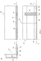
- Figure 1 shows an orthographic projection (front, side and plan view) of an example wetting apparatus 10 for applying a liquid agent onto a roller of a printing system.
- the example wetting apparatus 10 comprises an applicator unit 20 which is generally elongate along a lateral direction 2 defined by a transfer lip 22 of the applicator unit for transferring liquid agent to a roller.
- the applicator unit 20 extends from a liquid agent chamber 24 at a rear side towards the transfer lip 22 at a front side along an application direction 4 substantially perpendicular to the lateral direction 2, corresponding to flow of liquid agent through the applicator unit 20 for transfer to a roller.
- Upper and lower walls 26, 28 extend from the liquid agent chamber 24 to define a slit 30 between them for conveying liquid agent from the liquid agent chamber 24 to the transfer lip 22.
- the upper and lower walls 26, 28 are continuous with and extend from walls of the liquid agent chamber 24.
- the upper wall 26 extends from a lower end of an upright front wall of the liquid agent chamber 24 so that there is a curved join between them.
- the lower wall 28 extends from a lower end of an upright rear wall of the liquid agent chamber 24 so that there is a curved join between them.
- a height of the slit 30 (i.e. along a direction perpendicular to the upper wall 26 and towards the opposing lower wall 28) may be small as compared with its width (i.e. along the lateral direction 2) and depth (i.e. along the application direction 4).
- the height of the slit 30 may be between 0.2-1mm, for example 0.5mm.
- the width of the slit may be between 500mm and 1m for example.
- the depth of the slit 30 may be 10mm or more, such as 15mm or more or 20mm or more.
- the upper wall 26 extends beyond a lip of the lower wall (i.e. it extends from the liquid agent chamber along the application direction 4) and terminates at the laterally extending transfer lip 22.
- the upper lip extends approximately 5mm beyond the lip of the lower wall 28.
- the term lip is intended to denote the terminal edge of a wall that defines the slit 30.
- the applicator unit 20 receives a liquid agent, such as a primer or coating for a press print operation, in the liquid agent chamber 24.
- the liquid agent is provided to the slit under pressure so that it flows through the slit 30 along the application direction 4.
- the liquid agent may flow at a velocity such that it exits an aperture of the slit corresponding to the lip of the lower wall 28 and continues to flow along the upper wall 26 to reach the transfer lip 22, under action of surface tension forces.
- the liquid agent may flow at a speed of approximately 1m/s.
- the liquid agent may be transferred to an adjacent laterally-oriented roller rotating past the transfer lip 22 by forming a liquid bridge with a roller surface of the roller, as will be described below.
- a flow restrictor 50 is received in the slit 30 to prevent flow of liquid agent to a respective lateral portion of the transfer lip 22, and thereby prevent such transfer to a respective lateral portion of an adjacent roller, as will be described in detail below.
- the flow restrictor 50 is in the form of a cuboidal strip inserted into the slit 30 in an orientation so that it has a length along the application direction 4 greater than its width along the lateral direction 2.
- the flow restrictor 50 has a height along a direction corresponding to the height of the slit 30, and is dimensioned so that there is a clearance (i.e. in the height direction) between the flow restrictor 50 and the walls of the slit 30 when the flow restrictor 50 is received in the slit 30.
- the clearance may be between 0.01 and 0.1mm, for example between 0.01 and 0.03mm.
- a lateral portion of the slit 30 in which a flow restrictor is received is referred to as a restricted portion of the slit, as the presence of the flow restrictor restricts flow through the slit.
- a lateral portion of the slit which is free of any flow restrictor is referred to as an unrestricted portion.
- the clearance between the flow restrictor 50 and the slit 30 permits liquid agent to flow along the respective restricted portion of the slit.
- the clearance may be such that flow of liquid agent is permitted along the restricted portion at a reduced rate relative a flow of liquid agent through an adjacent unrestricted portion.
- liquid agent flowing along the restricted portion is discharged from the lip of the lower wall 28, whereas liquid agent flowing along the unrestricted portion continues to flow along the upper wall 26 to reach the transfer lip 22 and be transferred to a roller. Accordingly, the flow restrictor 50 prevents flow of liquid agent to a respective lateral portion of the transfer lip 22, and therefore prevents liquid agent being transferred to a corresponding lateral portion of a roller.
- Inserting a flow restrictor into the slit may provide a particularly simple and convenient way of installing a flow restrictor.
- the length along which the slit 30 extends from the liquid agent chamber 24 along the application direction may be such that a flow restrictor installed therein may be securely retained.
- the slit 30 may extend at least 10mm along the application direction, for example at least 15mm or at least 20.
- a slit of an applicator may be insufficiently deep (i.e. along an application direction) to securely retain a flow restrictor inserted therein.
- a flow restrictor may be received in a slit so that a proximal end of the flow restrictor (i.e. the end farthest into the slit) abuts a wall, partition or other formation within the slit or liquid agent chamber. This may prevent a piston pressure being applied by pressurised liquid agent in the chamber onto the flow restrictor which may otherwise drive the flow restrictor out of the slit.
- An example such partition 25 is shown in dashed lines in the side cross-sectional view of Figure 1 .
- Such a partition may also provide a baffle for liquid agent received into the liquid agent chamber 24, for example so that liquid agent is provided to the slit 30 at a substantially constant velocity over unrestricted portions, independent of local proximity to an inlet of liquid agent to the chamber.
- a portion of an example roller surface 60 of a roller is shown in dashed lines in the plan view of Figure 1 .
- the roller is cylindrical and rotatable around a roller axis parallel with the lateral direction 2, such that the roller surface 60 is spaced apart from the transfer lip by a uniform distance along its lateral extent for transfer of liquid agent, for example 2mm.
- the example roller surface 60 has two wetted zones 62 corresponding to unrestricted portions of the slit 30, and an un-wetted zone 64 corresponding to the restricted portion of the slit 30 where the flow restrictor 50 is received, with lateral boundaries between the zones 62, 64 being indicated with dashed lines.
- a flow restrictor may be provided with a boundary guide adjacent the transfer lip (i.e. when the flow restrictor is installed/received in the slit) to define a lateral boundary of a wetted zone on a roller.
- FIG. 2 An example flow restrictor 250 including an insert portion 252 and a boundary guide 260 is shown in Figure 2 .
- the boundary guide 260 is provided at an end of the insert portion 252 which is to be received in a slit, so that the boundary guide is disposed outside of the slit.
- the boundary guide 260 is fixedly attached and suspended from an end of the insert portion so at least a portion of it lies beneath the portion of the upper wall 26 that extends beyond the lip of the lower wall 28.
- a front portion of the boundary guide 260 i.e.
- a portion farthest from the slit along the application direction defines a boundary surface 262 that extends along the lateral direction 2 and a guide direction 6 perpendicular to the lateral direction to oppose a roller surface of a roller.
- the boundary surface is to receive liquid agent, for example liquid agent that may flow along a portion of the upper wall 26 adjacent the flow restrictor 50 under capillary action forces and flow over walls of the boundary guide 260 to reach the boundary surface.
- the boundary surface 262 may terminate at a boundary edge 264 extending perpendicular to the lateral direction 2 (e.g. along the guide direction 6) to prevent lateral migration of liquid agent on the boundary surface 262 beyond the boundary edge 264, and thereby define a lateral boundary of a wetted zone on the roller as will be described below.
- surface tension forces at the boundary edge 264 may be such that liquid agent received there is more readily transferred to an adjacent roller surface than laterally migrated over the boundary edge 264. Accordingly, the boundary edge 264 may thereby define a boundary between an un-wetted zone and a wetted zone on a roller.
- a portion of the boundary guide 260 may extend in front of the transfer lip 22 so that in use it is disposed between the transfer lip 22 and a roller surface as shown in Figure 2 . Further, a portion of the boundary guide 260 may extend above the transfer lip 22 with respect to the guide direction 6. By extending above the transfer lip 22, the boundary guide may prevent lateral migration of liquid agent along a pathway above the transfer lip, for example an overflow pathway which may extend from the upper wall 26 around the transfer lip 22.
- the boundary guide 260 may be integral with an insert portion 252 of the flow restrictor 250, or may be provided as a discrete element fixedly attached to the insert portion 252. In the example shown in Figure 2 , the boundary guide 260 is a discrete element fixedly attached to the insert portion 252.
- the boundary guide 260 and insert portion 252 may have different material compositions.
- the insert portion 252 may comprise spring steel and the boundary guide may comprise PTFE or a PTFE coating.
- a portion of a flow restrictor which is to be received in a slit may comprise a material resistant to corrosion in the liquid agent, for example stainless steel, which has good corrosive resistance to high PH liquids, such as primers and coatings as may be used in press printing.
- the boundary guide 260 comprises two boundary surfaces 262 terminating at respective boundary edges 264 laterally spaced apart by a void 266. Providing a void adjacent the boundary edges 264 may prevent lateral migration of liquid agent on the boundary surfaces 262 beyond the boundary edge 264. Accordingly, the boundary edge 264 may thereby define an un-wetted zone on the roller corresponding to the void as will be illustrated in the further figures.
- the boundary surfaces 262 are disposed forward of the intermediate portion 268 with respect to the application direction from the slit to a roller (which may be equally referred to as from the slit to the transfer lip).
- the arrangement of the boundary surfaces 262 and the intermediate portion 268 is such that the intermediate portion 268 is recessed between the boundary surfaces 266 (i.e. the void is in front of the intermediate portion 268).
- the intermediate portion 268 may comprise a locating formation 270 to cooperate with a corresponding locating feature of an apparatus for placement of the flow restrictor 250, i.e. for placement of the flow restrictor 250 in and along the slit, as will be described below.
- a locating formation 270 is provided as a recess in the intermediate portion 268, in particular a cylindrical recess 270 for receiving a corresponding cylindrical locating pin.
- the locating formation 270 may take any appropriate form, for example a differently shaped recess or protrusion.
- Figure 3 shows a further example flow restrictor 350 for use with the applicator unit of Figure 1 , which is similar to the flow restrictor 250 of Figure 2 but differing with respect to the boundary surface 362 and profile of the boundary guide 360.
- the boundary guide 360 is provided at an end of an insert portion 352 as described above with respect to Figure 2 , and is suspended from it so that at least a portion of it lies beneath the portion of the protruding part of the upper wall 26 that extends beyond the lip of the lower wall 28, as above.
- the boundary guide 360 has chamfered forward edges 363 to guide liquid agent along side surfaces of the boundary guide 360 towards forward boundary surfaces 362 that are to oppose a roller.
- the boundary guide 360 comprises two parallel boundary surfaces 362 extending along a guide direction 6 perpendicular to the lateral direction 2, and terminating at boundary edges 364 laterally spaced apart by a void 366 as described above.
- the boundary guide 360 further comprises an upper boundary surface 374 which is to extend above and in front of the transfer lip 22 when the flow restrictor 350 is received in the slit of an applicator unit.
- the upper boundary surface 374 is to prevent lateral migration of liquid agent along a pathway extending above the transfer lip, for example an overflow pathway as described above.
- the upper boundary surface 374 extends laterally to bridge the two parallel boundary surfaces 362 at its lower side, and extends upwardly away from the transfer lip 22 to provide a barrier to liquid agent that may otherwise flow from the upper wall 26 up and over a portion of the boundary guide 360.
- the upper boundary surface 374 is generally rectangular.
- the upper boundary surface 374 has a greater lateral extent than the two parallel boundary surfaces 362 together to prevent overflow from adjacent lateral portions of the upper wall 26.
- the boundary guide 360 is discrete from the insert portion 352 and fixedly attached to it.
- Figure 4 shows a further example of a flow restrictor 450 for use with the applicator unit of Figure 1 , as illustrated with reference to a location of a transfer lip 22 (shown with a dashed line) when the flow restrictor 450 is installed in the slit of the applicator unit of Figure 1 .
- the flow restrictor 450 comprises an insert portion 452 and a boundary guide 460 which are integrally formed with one another. However, in other examples, they may be discrete from one another.
- the insert portion 452 is biased away from a planar configuration for retention in a slit.
- an end region of the insert portion 452 is deflected away from the plane of a center region of the insert portion about a hinge line. This bias may cause the insert portion to apply a biasing force on opposing surfaces of a slot in which it is received, which may provide for an increased frictional force resisting dislodging of the insert portion within the slot.
- the boundary guide 460 comprises two rails 461 defining respective boundary surfaces 462 which extend along a lateral direction 2 parallel with the transfer lip 22 and a guide direction 6 which is perpendicular to the lateral direction.
- the two rails 461 extend along the guide direction 6 from a lip portion 480 of the boundary guide 460 adjacent the lip 22 (e.g. at the junction between the boundary guide 460 and the insert portion) to a distal support portion 482.
- the distal support portion 482 is to rest against a support structure of the apparatus of Figure 1 , as will be described below.
- the distal support portion 482 comprises a laterally extending member which has a greater lateral extent than the rails 461 (when considered together). Increasing the lateral extent of the support portion 482 may provide increased stability to the location of the flow restrictor 450 in the slot, as it may provide increased resistance to rotation of the flow restrictor 450 within the slot.
- the boundary guide 460 further comprises an intermediate portion 468 laterally between the rails 461 and recessed relative the rails 461 with respect to the application direction, so that in use the intermediate portion 468 is spaced further from a roller than the rails 461.
- the intermediate portion 468 may extend between the lip portion 480 of the boundary guide 460 adjacent to the transfer lip 22 to the distal support portion 482.
- the intermediate portion 468 may be integrally attached to the distal support portion and may be affixed to the lip portion 480, for example by being received in a slot in the lip portion 481 and optionally secured therein (for example by welding, by deformation of a protruding part of the intermediate portion beyond the slot, or by a mechanical fastener).
- Providing the rails forward of the intermediate of the intermediate portion may provide structural rigidity to the boundary guide 460.
- the intermediate portion 468 comprises a locating formation 470 to cooperate with a corresponding locating feature of an apparatus for placement of the flow restrictor 450.
- the example locating formation 470 comprises a circular hole in the intermediate portion 468 which may receive a locating pin as will be described below.
- the insert portion 452 may be integrally formed with the boundary guide 460.
- the insert portion 452 and the boundary guide 460 are integrally formed as a unitary body, for example from a sheet material.
- a particular example may be sheet metal such as spring steel.
- the intermediate portion may be punched or otherwise separated from the rails on three sides so that it is cantilever-mounted to one of the lip portion 480 and the distal support portion 482, and may be affixed to the opposing one of the lip portion 480 and the distal support portion 482.
- the intermediate portion 468 is cantilever-mounted to the distal support portion 482 and affixed to the lip portion 480 by being received in a slot 481 in the lip portion.
- a slot 481 in the lip portion may be punched or laser cut, for example.
- Figure 5 shows the example flow restrictor 450 of Figure 4 as installed in a slit 30 of the applicator unit 20 of Figure 1 .
- the applicator unit comprises a slit 30 defined between upper and lower walls 26, 28 which extend from a liquid agent chamber 24 as described above.
- the applicator unit 20 may further comprise support structure adjacent an aperture of the slit 30.
- there is a support structure comprising an upper support wall 32 and an opposing lower support wall 34 which engage the upper and lower walls 26, 28 on upper and lower sides respectively.
- the support structure may provide a reinforcing support to the upper and lower walls 26, 28 and thereby maintain dimensional accuracy of the aperture of the slot a 30 from which liquid agent is discharged.
- the insert portion 452 is received in the slit 30 and the boundary guide 460 is disposed outside of the slot.
- the flow restrictor 450 is bent at the lip portion 480 so that the rails 461 extend below the transfer lip 22 of the upper wall 26 along a guide direction 6 so that the boundary surfaces 462 may oppose a roller.
- a roller surface 60 of an example roller is depicted in dashed lines by way of example only.
- the guide direction 6 is perpendicular to the lateral direction and approximately perpendicular to the application direction 4.
- each of the rails 461 and the intermediate portion 468 extend form the lip portion 480 to the distal portion 482, with the rails 461 being disposed forward of the intermediate portion 468 with respect to the application direction 4.
- the distal support portion 482 extends towards the applicator unit 20 to rest against a support structure of the applicator unit 20 - in this particular example against the lower support wall 34.
- the distal support portion 482 may rest against any other component of an applicator unit 20 or a component fixed with respect to it.
- Figure 6 shows an example apparatus 600 comprising an example applicator unit 20 as described above and a plurality of example flow restrictors 610, 620, together with an example roller 630 having a roller surface 632 which opposes the transfer lip 22 of the applicator unit 20 over a transfer gap 634.
- the flow restrictors 610, 620 comprise two flow limiters 610 disposed towards opposing lateral sides of the slit 30 which define lateral boundaries of a total wetted zone 636 of the roller 630 (i.e. the cumulative lateral extent over which any portion of the roller is wetted by liquid agent transfer from the applicator unit).
- the flow restrictors 610, 620 further comprise two lane inserts 620 at intermediate locations in the slot (i.e. intermediate with respect to the lateral extent of the slot over which liquid agent is to be discharged) to define corresponding dry lanes 638 on the roller surface 632.
- an apparatus may comprise a flow limiter 610 with no lane inserts 620, and similarly an apparatus may comprise a lane insert 620 with no flow limiters.
- any suitable form of a flow restrictor may be used for each of the flow limiters 610 and lane inserts 620, for example, the flow limiters and lane inserts may be in accordance with any of the example flow restrictors 250, 350, 450 as described herein.
- each of the flow limiters 610 and lane inserts 620 comprise flow restrictors in accordance with the example flow restrictor 350 described above with respect to Figure 3 , and thereby comprise an insert portion 352 and a discrete boundary guide 360 which is at least partly disposed between the transfer lip 22 and the roller surface 632.
- a flow limiter 610 may be moveable along the lateral direction to vary a lateral position of a boundary of the total wetted zone 636.
- a flow limiter 610 may comprise or be provided with any suitable actuation arrangement for moving the flow limiter 610 along the lateral direction.
- each flow limiter comprises an arm portion 612 which extends laterally into the slit 30 from a respective lateral end of the slit 30, and a tab portion 614 extending from the arm portion 612 towards the transfer lip 22 which corresponds to a flow restrictor as described with respect to any of the above examples, for example the flow restrictor 350 described above with respect to Figure 3
- the arm portion 612 and the tab portion 614 are received in the slit 30 with a clearance so that they define a corresponding restricted portion of the slit as described above.
- the arm portion 612 extends outside of the slit 30 to engage a drive 616 for driving lateral movement of the flow limiter 610.
- the drive 616 and arm portion 612 may engage by a rack and pinion arrangement or any other suitable actuation arrangement.
- the arm portion 612 may comprise an array of drive holes along its length and the drive 616 may comprise a drive wheel provided with drive projections for engaging the drive holes.
- the drive may comprise a worm screw.
- the drive 616 may comprise a stepper motor or other suitable actuation device.
- the drive arrangement may comprise a linear encoder, which may be to provide a signal indicating an absolute lateral position of the flow limiter. Accordingly, the lateral position may be derived and controlled irrespective of any intervening power down of the apparatus.
- each drive 616 is disposed outside of the liquid agent chamber 24 and outside of the slit 30. Accordingly, each drive 616 may be separate from and not immersed in the liquid agent in use. In previously considered arrangements, a drive may be disposed in a liquid agent chamber or otherwise exposed to it. Liquid agent may be damaging to components of a drive.
- the drive 616 may be operated to move the flow limiter 610 along the lateral direction to thereby move the lateral location of a respective boundary of a total wetted zone 636 on the roller surface 632.
- liquid agent is caused to flow through the slit 30 along the application direction 4.
- the liquid agent flows at a reduced velocity relative a flow of liquid agent through an adjacent unrestricted portion between the flow limiter 610 and any corresponding flow restrictor (e.g. a flow limiter 610 or lane insert 620).
- the reduced velocity is such that the liquid agent is discharged from the lip of the lower wall of the slit, rather than flowing along the upper wall to reach the transfer lip 22 for transfer to the roller 630.
- the reduced velocity may be XXm/s, whereas a velocity through an unrestricted portion of the slit may be approximately 1m/s.
- a lateral end portion of the roller 630 from an extreme end of the roller up to the boundary of the wetted zone 636 does not receive liquid agent in use, and is thereby referred to as an un-wetted end zone 637 herein.
- liquid agent flowing along an unrestricted portion of the slit reaches a corresponding lateral portion of the transfer lip 22 and is thereby transferred to a wetted zone of the roller surface 632.
- each lane insert 620 defines a corresponding restricted portion of the slit 30 which prevents a flow of liquid agent to a corresponding lateral portion of the transfer lip 22 in the same way.
- the flow restrictors are in accordance with the example flow restrictor described above with respect to Figure 3 , and accordingly are provided with boundary guides which have boundary surfaces to face the roller, and which define boundary edges extending perpendicular to the lateral direction to prevent lateral migration of liquid agent along the boundary surface beyond the boundary edge.
- the boundary guides have an overall width corresponding to the width of the respective insert portion, and the boundary surface opposes the roller 630 so that in this example the boundary edges are laterally inset within the overall width of the boundary guide.
- the un-wetted dry lane 638 has a lateral extent less than the width of the respective insert portion.
- Figure 7 shows an example applicator unit 20 as described above with respect to Figure 1 in plan view with hidden detail relating to the insertion of example insert tabs 620 into the slit 30 of the applicator unit 20.
- the example insert tabs 620 are as described above with respect to Figure 6 .
- Figure 7 shows an example insert jig 700 for aligning a flow restrictor such as an insert tab 620 with a predetermined lateral position along the slit 30 (i.e. a predetermined lateral position along the applicator unit 20).
- Figure 7 shows the applicator unit 20 with insert tabs 620 received in the slit 30 of the applicator unit 20.
- the insert tabs 620 may be inserted into the slit 30 before the insert jig is aligned with the applicator unit 20.
- the insert jig comprises a support body 702.
- the insert jig 700 and the applicator unit 20 have cooperating formations 704, 706 respectively for aligning the jig with a predetermined lateral location with respect to the applicator unit.
- the cooperating formations 704, 706 may comprise corresponding laterally-spaced apart pairs of projections and recesses.
- the insert jig comprises protruding alignment pins and the applicator unit 20 comprises cooperating alignment recesses.
- the insert jig 700 further comprises a restrictor guide 710.
- a restrictor guide 710 In the example shown in Figure 7 , there are two restrictor guides 710 for aligning two respective flow restrictors.
- Each restrictor guide 710 is laterally slidable along the insert jig 700 and is to cooperate with a corresponding flow restrictor 620, for example by cooperating locating formations.
- the cooperating locating formations may be a locating pin protruding from the restrictor guide 710 towards the flow restrictor along the application direction 4 and a cooperating locating hole 270 in the flow restrictor 620 to receive the locating pin.
- Example locating holes 270, 370, 470 are described with respect the flow restrictors of Figures 2-4 respectively.
- Each restrictor guide 710 is to slide laterally along the insert jig to drive corresponding sliding movement of the respective flow restrictor within the slit 30.
- the insert jig comprises a rail 707 on which each of the restrictor guides 710 are slidably mounted.
- the insert jig 700 further comprises a laterally-extending marking scale 708, such as ruler markings.
- the marking scale 708 may indicate alignment positions for a flow restrictor with respect to the slit 30 when the insert jig is aligned with the applicator unit.
- FIG. 8 is a flowchart of an example method of installing a flow restrictor in a wetting apparatus which may be in accordance with any of the examples described herein.
- the wetting apparatus comprises an applicator unit having a liquid agent chamber, upper and lower walls extending from the liquid agent chamber to define a slit between them for conveying liquid agent, the slit having a width along a lateral direction; wherein the upper wall extends beyond a lip of the lower wall and terminates at a laterally extending transfer lip to transfer liquid agent conveyed along the upper wall from the slit to a roller.
- a flow restrictor is installed in the slit to prevent flow of liquid agent to a respective lateral portion of the transfer lip, thereby defining a restricted portion of the slit and an adjacent unrestricted portion of the slit.
- the flow restrictor is installed so that there is a clearance between the flow restrictor and the slit which permits liquid agent to flow along the restricted portion at a reduced velocity relative a flow of liquid agent through the unrestricted portion, such that liquid agent flowing along the restricted portion is discharged from the lip of the lower wall.
- Figure 9 shows a further example method including aligning the flow restrictor with the slit using an insert jig, such as an insert jig as described with respect to Figure 7 above.
- the flow restrictor is installed in the slot as described above. In this example, there is a predetermined lateral location for the flow restrictor and the flow restrictor is not in the predetermined location after initial insertion.
- cooperating locating features on the flow restrictor and a restrictor guide of the insert jig are engaged to align the flow restrictor with the restrictor guide.
- the restrictor guide is slid to align the flow restrictor relative the insert jig.
- the insert jig includes markings corresponding particular locations along the slit.
- the insert jig may include ruler-style markings
- the restrictor guide is slid along the insert jig to align a marking feature of the restrictor guide with a predetermined location on the insert jig markings, for example a predetermined lateral location for the insert jig.
- the insert jig is aligned with the applicator unit.
- the flow restrictor becomes aligned with a predetermined lateral position along the slit (i.e. along the applicator unit).
Landscapes
- Coating Apparatus (AREA)
Description
- In press printing, a liquid agent such as an ink, a coating or a primer is applied to a wettable surface of a roller, for example an anilox or gravure roller. An auxiliary roller may be provided to selectively wet portions of the roller. For example, the auxiliary roller may have radially-extending rubber portions that engage and wet selected portions of the roller.
-
US20160354800 discloses a coater assembly including an array of side-by-side selectively closable slot portions to control pressurized fluid flow onto a substrate during relative movement between the coater assembly and the substrate.CN102529334 discloses a printing ink fountain with a movable separation plate.US20020134263 discloses a device for receiving an ink supply in an ink feed device of a printing machine, where the ink supply is received in a reservoir having elements formed with laterally bounding surfaces and contact surfaces for sealing off the ink supply. - The scope of the invention is defined by the appended claims.
- Examples will now be described, by way of non-limiting example, with reference to the accompanying drawings, in which:
-
Figure 1 is an orthographic projection of a simplified example wetting apparatus for wetting a roller of a printing system; and -
Figures 2-3 are perspective views of example boundary guides; -
Figure 4 is a perspective view of an example flow restrictor; -
Figure 5 is a side cross sectional view of an example wetting apparatus; -
Figure 6 is a plan view of an example wetting apparatus and roller of a printing apparatus with hidden view detail; -
Figure 7 is a plan view of an example wetting apparatus and insert jig with hidden view detail; -
Figure 8 is a flowchart of an example method of installing a flow restrictor; and -
Figure 9 is a flowchart of a further example method of installing a flow restrictor. -
Figure 1 shows an orthographic projection (front, side and plan view) of anexample wetting apparatus 10 for applying a liquid agent onto a roller of a printing system. - The
example wetting apparatus 10 comprises anapplicator unit 20 which is generally elongate along alateral direction 2 defined by atransfer lip 22 of the applicator unit for transferring liquid agent to a roller. In this example, theapplicator unit 20 extends from aliquid agent chamber 24 at a rear side towards thetransfer lip 22 at a front side along anapplication direction 4 substantially perpendicular to thelateral direction 2, corresponding to flow of liquid agent through theapplicator unit 20 for transfer to a roller. - Upper and
lower walls liquid agent chamber 24 to define aslit 30 between them for conveying liquid agent from theliquid agent chamber 24 to thetransfer lip 22. In this particular example, the upper andlower walls liquid agent chamber 24. For example, as shown in the side view, in this example theupper wall 26 extends from a lower end of an upright front wall of theliquid agent chamber 24 so that there is a curved join between them. Similarly, in this example thelower wall 28 extends from a lower end of an upright rear wall of theliquid agent chamber 24 so that there is a curved join between them. - By way of example, a height of the slit 30 (i.e. along a direction perpendicular to the
upper wall 26 and towards the opposing lower wall 28) may be small as compared with its width (i.e. along the lateral direction 2) and depth (i.e. along the application direction 4). For example, the height of theslit 30 may be between 0.2-1mm, for example 0.5mm. The width of the slit may be between 500mm and 1m for example. The depth of theslit 30 may be 10mm or more, such as 15mm or more or 20mm or more. - In this example, the
upper wall 26 extends beyond a lip of the lower wall (i.e. it extends from the liquid agent chamber along the application direction 4) and terminates at the laterally extendingtransfer lip 22. In this particular example, the upper lip extends approximately 5mm beyond the lip of thelower wall 28. The term lip is intended to denote the terminal edge of a wall that defines theslit 30. - In use, the
applicator unit 20 receives a liquid agent, such as a primer or coating for a press print operation, in theliquid agent chamber 24. The liquid agent is provided to the slit under pressure so that it flows through theslit 30 along theapplication direction 4. In the absence of a blockage in theslit 30, the liquid agent may flow at a velocity such that it exits an aperture of the slit corresponding to the lip of thelower wall 28 and continues to flow along theupper wall 26 to reach thetransfer lip 22, under action of surface tension forces. For example, the liquid agent may flow at a speed of approximately 1m/s. From thetransfer lip 22, the liquid agent may be transferred to an adjacent laterally-oriented roller rotating past thetransfer lip 22 by forming a liquid bridge with a roller surface of the roller, as will be described below. - As shown in
Figure 1 , in this example aflow restrictor 50 is received in theslit 30 to prevent flow of liquid agent to a respective lateral portion of thetransfer lip 22, and thereby prevent such transfer to a respective lateral portion of an adjacent roller, as will be described in detail below. - In this particular example, the
flow restrictor 50 is in the form of a cuboidal strip inserted into theslit 30 in an orientation so that it has a length along theapplication direction 4 greater than its width along thelateral direction 2. Theflow restrictor 50 has a height along a direction corresponding to the height of theslit 30, and is dimensioned so that there is a clearance (i.e. in the height direction) between theflow restrictor 50 and the walls of theslit 30 when theflow restrictor 50 is received in theslit 30. For example, the clearance may be between 0.01 and 0.1mm, for example between 0.01 and 0.03mm. In the present disclosure a lateral portion of theslit 30 in which a flow restrictor is received is referred to as a restricted portion of the slit, as the presence of the flow restrictor restricts flow through the slit. In contrast, a lateral portion of the slit which is free of any flow restrictor is referred to as an unrestricted portion. The clearance between theflow restrictor 50 and theslit 30 permits liquid agent to flow along the respective restricted portion of the slit. The clearance may be such that flow of liquid agent is permitted along the restricted portion at a reduced rate relative a flow of liquid agent through an adjacent unrestricted portion. Accordingly, liquid agent flowing along the restricted portion is discharged from the lip of thelower wall 28, whereas liquid agent flowing along the unrestricted portion continues to flow along theupper wall 26 to reach thetransfer lip 22 and be transferred to a roller. Accordingly, theflow restrictor 50 prevents flow of liquid agent to a respective lateral portion of thetransfer lip 22, and therefore prevents liquid agent being transferred to a corresponding lateral portion of a roller. - Inserting a flow restrictor into the slit (i.e. along the
application direction 4 through an aperture of the slit) may provide a particularly simple and convenient way of installing a flow restrictor. The length along which theslit 30 extends from theliquid agent chamber 24 along the application direction may be such that a flow restrictor installed therein may be securely retained. For example, in an apparatus having a slit height of approximately 0.5mm, theslit 30 may extend at least 10mm along the application direction, for example at least 15mm or at least 20. In previously considered arrangements, a slit of an applicator may be insufficiently deep (i.e. along an application direction) to securely retain a flow restrictor inserted therein. - In some examples, a flow restrictor may be received in a slit so that a proximal end of the flow restrictor (i.e. the end farthest into the slit) abuts a wall, partition or other formation within the slit or liquid agent chamber. This may prevent a piston pressure being applied by pressurised liquid agent in the chamber onto the flow restrictor which may otherwise drive the flow restrictor out of the slit. An example
such partition 25 is shown in dashed lines in the side cross-sectional view ofFigure 1 . Such a partition may also provide a baffle for liquid agent received into theliquid agent chamber 24, for example so that liquid agent is provided to theslit 30 at a substantially constant velocity over unrestricted portions, independent of local proximity to an inlet of liquid agent to the chamber. - A portion of an
example roller surface 60 of a roller is shown in dashed lines in the plan view ofFigure 1 . In this example, the roller is cylindrical and rotatable around a roller axis parallel with thelateral direction 2, such that theroller surface 60 is spaced apart from the transfer lip by a uniform distance along its lateral extent for transfer of liquid agent, for example 2mm. Theexample roller surface 60 has twowetted zones 62 corresponding to unrestricted portions of theslit 30, and an un-wetted zone 64 corresponding to the restricted portion of theslit 30 where theflow restrictor 50 is received, with lateral boundaries between thezones 62, 64 being indicated with dashed lines. - In some examples, a flow restrictor may be provided with a boundary guide adjacent the transfer lip (i.e. when the flow restrictor is installed/received in the slit) to define a lateral boundary of a wetted zone on a roller.
- An
example flow restrictor 250 including aninsert portion 252 and aboundary guide 260 is shown inFigure 2 . In this example, theboundary guide 260 is provided at an end of theinsert portion 252 which is to be received in a slit, so that the boundary guide is disposed outside of the slit. In this example, theboundary guide 260 is fixedly attached and suspended from an end of the insert portion so at least a portion of it lies beneath the portion of theupper wall 26 that extends beyond the lip of thelower wall 28. A front portion of the boundary guide 260 (i.e. a portion farthest from the slit along the application direction) defines aboundary surface 262 that extends along thelateral direction 2 and aguide direction 6 perpendicular to the lateral direction to oppose a roller surface of a roller. The boundary surface is to receive liquid agent, for example liquid agent that may flow along a portion of theupper wall 26 adjacent theflow restrictor 50 under capillary action forces and flow over walls of theboundary guide 260 to reach the boundary surface. - The
boundary surface 262 may terminate at aboundary edge 264 extending perpendicular to the lateral direction 2 (e.g. along the guide direction 6) to prevent lateral migration of liquid agent on theboundary surface 262 beyond theboundary edge 264, and thereby define a lateral boundary of a wetted zone on the roller as will be described below. In particular, surface tension forces at theboundary edge 264 may be such that liquid agent received there is more readily transferred to an adjacent roller surface than laterally migrated over theboundary edge 264. Accordingly, theboundary edge 264 may thereby define a boundary between an un-wetted zone and a wetted zone on a roller. - A portion of the
boundary guide 260 may extend in front of thetransfer lip 22 so that in use it is disposed between thetransfer lip 22 and a roller surface as shown inFigure 2 . Further, a portion of theboundary guide 260 may extend above thetransfer lip 22 with respect to theguide direction 6. By extending above thetransfer lip 22, the boundary guide may prevent lateral migration of liquid agent along a pathway above the transfer lip, for example an overflow pathway which may extend from theupper wall 26 around thetransfer lip 22. - The
boundary guide 260 may be integral with aninsert portion 252 of theflow restrictor 250, or may be provided as a discrete element fixedly attached to theinsert portion 252. In the example shown inFigure 2 , theboundary guide 260 is a discrete element fixedly attached to theinsert portion 252. Theboundary guide 260 andinsert portion 252 may have different material compositions. For example, theinsert portion 252 may comprise spring steel and the boundary guide may comprise PTFE or a PTFE coating. A portion of a flow restrictor which is to be received in a slit may comprise a material resistant to corrosion in the liquid agent, for example stainless steel, which has good corrosive resistance to high PH liquids, such as primers and coatings as may be used in press printing. - In the example shown in
Figure 2 , theboundary guide 260 comprises twoboundary surfaces 262 terminating at respective boundary edges 264 laterally spaced apart by avoid 266. Providing a void adjacent the boundary edges 264 may prevent lateral migration of liquid agent on the boundary surfaces 262 beyond theboundary edge 264. Accordingly, theboundary edge 264 may thereby define an un-wetted zone on the roller corresponding to the void as will be illustrated in the further figures. - In the
example boundary guide 260 shown inFigure 2 , there is anintermediate portion 268 laterally between the two boundary surfaces 262. The boundary surfaces 262 are disposed forward of theintermediate portion 268 with respect to the application direction from the slit to a roller (which may be equally referred to as from the slit to the transfer lip). The arrangement of the boundary surfaces 262 and theintermediate portion 268 is such that theintermediate portion 268 is recessed between the boundary surfaces 266 (i.e. the void is in front of the intermediate portion 268). Theintermediate portion 268 may comprise a locatingformation 270 to cooperate with a corresponding locating feature of an apparatus for placement of theflow restrictor 250, i.e. for placement of theflow restrictor 250 in and along the slit, as will be described below. In this particular example, a locatingformation 270 is provided as a recess in theintermediate portion 268, in particular acylindrical recess 270 for receiving a corresponding cylindrical locating pin. However, in other examples the locatingformation 270 may take any appropriate form, for example a differently shaped recess or protrusion. -
Figure 3 shows a furtherexample flow restrictor 350 for use with the applicator unit ofFigure 1 , which is similar to theflow restrictor 250 ofFigure 2 but differing with respect to theboundary surface 362 and profile of theboundary guide 360. Theboundary guide 360 is provided at an end of aninsert portion 352 as described above with respect toFigure 2 , and is suspended from it so that at least a portion of it lies beneath the portion of the protruding part of theupper wall 26 that extends beyond the lip of thelower wall 28, as above. - In this example, the
boundary guide 360 has chamfered forward edges 363 to guide liquid agent along side surfaces of theboundary guide 360 towards forward boundary surfaces 362 that are to oppose a roller. In this example, theboundary guide 360 comprises two parallel boundary surfaces 362 extending along aguide direction 6 perpendicular to thelateral direction 2, and terminating at boundary edges 364 laterally spaced apart by a void 366 as described above. Theboundary guide 360 further comprises anupper boundary surface 374 which is to extend above and in front of thetransfer lip 22 when theflow restrictor 350 is received in the slit of an applicator unit. Theupper boundary surface 374 is to prevent lateral migration of liquid agent along a pathway extending above the transfer lip, for example an overflow pathway as described above. In this particular example, theupper boundary surface 374 extends laterally to bridge the two parallel boundary surfaces 362 at its lower side, and extends upwardly away from thetransfer lip 22 to provide a barrier to liquid agent that may otherwise flow from theupper wall 26 up and over a portion of theboundary guide 360. In this example, theupper boundary surface 374 is generally rectangular. Theupper boundary surface 374 has a greater lateral extent than the two parallel boundary surfaces 362 together to prevent overflow from adjacent lateral portions of theupper wall 26. - As with the
flow restrictor 250 ofFigure 2 , in this example theboundary guide 360 is discrete from theinsert portion 352 and fixedly attached to it. -
Figure 4 shows a further example of aflow restrictor 450 for use with the applicator unit ofFigure 1 , as illustrated with reference to a location of a transfer lip 22 (shown with a dashed line) when theflow restrictor 450 is installed in the slit of the applicator unit ofFigure 1 . In this particular example, theflow restrictor 450 comprises aninsert portion 452 and aboundary guide 460 which are integrally formed with one another. However, in other examples, they may be discrete from one another. - In this example, the
insert portion 452 is biased away from a planar configuration for retention in a slit. In particular, as shown inFigure 4 , an end region of theinsert portion 452 is deflected away from the plane of a center region of the insert portion about a hinge line. This bias may cause the insert portion to apply a biasing force on opposing surfaces of a slot in which it is received, which may provide for an increased frictional force resisting dislodging of the insert portion within the slot. - The
boundary guide 460 comprises tworails 461 defining respective boundary surfaces 462 which extend along alateral direction 2 parallel with thetransfer lip 22 and aguide direction 6 which is perpendicular to the lateral direction. The tworails 461 extend along theguide direction 6 from alip portion 480 of theboundary guide 460 adjacent the lip 22 (e.g. at the junction between theboundary guide 460 and the insert portion) to adistal support portion 482. Thedistal support portion 482 is to rest against a support structure of the apparatus ofFigure 1 , as will be described below. - In this example, the
distal support portion 482 comprises a laterally extending member which has a greater lateral extent than the rails 461 (when considered together). Increasing the lateral extent of thesupport portion 482 may provide increased stability to the location of theflow restrictor 450 in the slot, as it may provide increased resistance to rotation of theflow restrictor 450 within the slot. - In this particular example, the
boundary guide 460 further comprises anintermediate portion 468 laterally between therails 461 and recessed relative therails 461 with respect to the application direction, so that in use theintermediate portion 468 is spaced further from a roller than therails 461. Theintermediate portion 468 may extend between thelip portion 480 of theboundary guide 460 adjacent to thetransfer lip 22 to thedistal support portion 482. In some examples, theintermediate portion 468 may be integrally attached to the distal support portion and may be affixed to thelip portion 480, for example by being received in a slot in thelip portion 481 and optionally secured therein (for example by welding, by deformation of a protruding part of the intermediate portion beyond the slot, or by a mechanical fastener). Providing the rails forward of the intermediate of the intermediate portion may provide structural rigidity to theboundary guide 460. - In this particular example, the
intermediate portion 468 comprises a locatingformation 470 to cooperate with a corresponding locating feature of an apparatus for placement of theflow restrictor 450. Theexample locating formation 470 comprises a circular hole in theintermediate portion 468 which may receive a locating pin as will be described below. - The
insert portion 452 may be integrally formed with theboundary guide 460. In the particular example shown inFigure 4 , theinsert portion 452 and theboundary guide 460 are integrally formed as a unitary body, for example from a sheet material. A particular example may be sheet metal such as spring steel. In the sheet material body, the intermediate portion may be punched or otherwise separated from the rails on three sides so that it is cantilever-mounted to one of thelip portion 480 and thedistal support portion 482, and may be affixed to the opposing one of thelip portion 480 and thedistal support portion 482. In the particular example shown inFigure 4 , theintermediate portion 468 is cantilever-mounted to thedistal support portion 482 and affixed to thelip portion 480 by being received in aslot 481 in the lip portion. Aslot 481 in the lip portion may be punched or laser cut, for example. -
Figure 5 shows the example flow restrictor 450 ofFigure 4 as installed in aslit 30 of theapplicator unit 20 ofFigure 1 . The applicator unit comprises aslit 30 defined between upper andlower walls liquid agent chamber 24 as described above. Theapplicator unit 20 may further comprise support structure adjacent an aperture of theslit 30. In the particular example shown inFigure 5 , there is a support structure comprising anupper support wall 32 and an opposinglower support wall 34 which engage the upper andlower walls lower walls - As shown, the
insert portion 452 is received in theslit 30 and theboundary guide 460 is disposed outside of the slot. The flow restrictor 450 is bent at thelip portion 480 so that therails 461 extend below thetransfer lip 22 of theupper wall 26 along aguide direction 6 so that the boundary surfaces 462 may oppose a roller. Aroller surface 60 of an example roller is depicted in dashed lines by way of example only. In this example, theguide direction 6 is perpendicular to the lateral direction and approximately perpendicular to theapplication direction 4. - As shown in
Figure 5 , each of therails 461 and theintermediate portion 468 extend form thelip portion 480 to thedistal portion 482, with therails 461 being disposed forward of theintermediate portion 468 with respect to theapplication direction 4. In this particular example thedistal support portion 482 extends towards theapplicator unit 20 to rest against a support structure of the applicator unit 20 - in this particular example against thelower support wall 34. However, in other examples, thedistal support portion 482 may rest against any other component of anapplicator unit 20 or a component fixed with respect to it. -
Figure 6 shows anexample apparatus 600 comprising anexample applicator unit 20 as described above and a plurality ofexample flow restrictors example roller 630 having aroller surface 632 which opposes thetransfer lip 22 of theapplicator unit 20 over atransfer gap 634. In this example, theflow restrictors flow limiters 610 disposed towards opposing lateral sides of theslit 30 which define lateral boundaries of a total wettedzone 636 of the roller 630 (i.e. the cumulative lateral extent over which any portion of the roller is wetted by liquid agent transfer from the applicator unit). The flow restrictors 610, 620 further comprise two lane inserts 620 at intermediate locations in the slot (i.e. intermediate with respect to the lateral extent of the slot over which liquid agent is to be discharged) to define correspondingdry lanes 638 on theroller surface 632. - In other examples, an apparatus may comprise a
flow limiter 610 with no lane inserts 620, and similarly an apparatus may comprise alane insert 620 with no flow limiters. - Any suitable form of a flow restrictor may be used for each of the
flow limiters 610 and lane inserts 620, for example, the flow limiters and lane inserts may be in accordance with any of theexample flow restrictors - In this particular example, each of the
flow limiters 610 and lane inserts 620 comprise flow restrictors in accordance with theexample flow restrictor 350 described above with respect toFigure 3 , and thereby comprise aninsert portion 352 and adiscrete boundary guide 360 which is at least partly disposed between thetransfer lip 22 and theroller surface 632. - A
flow limiter 610 may be moveable along the lateral direction to vary a lateral position of a boundary of the total wettedzone 636. Aflow limiter 610 may comprise or be provided with any suitable actuation arrangement for moving theflow limiter 610 along the lateral direction. - In the
particular example apparatus 600 ofFigure 6 , each flow limiter comprises anarm portion 612 which extends laterally into theslit 30 from a respective lateral end of theslit 30, and atab portion 614 extending from thearm portion 612 towards thetransfer lip 22 which corresponds to a flow restrictor as described with respect to any of the above examples, for example theflow restrictor 350 described above with respect toFigure 3 - In this particular example, the
arm portion 612 and thetab portion 614 are received in theslit 30 with a clearance so that they define a corresponding restricted portion of the slit as described above. Thearm portion 612 extends outside of theslit 30 to engage adrive 616 for driving lateral movement of theflow limiter 610. For example, thedrive 616 andarm portion 612 may engage by a rack and pinion arrangement or any other suitable actuation arrangement. For example, when a rack and pinion arrangement is used, thearm portion 612 may comprise an array of drive holes along its length and thedrive 616 may comprise a drive wheel provided with drive projections for engaging the drive holes. The drive may comprise a worm screw. Thedrive 616 may comprise a stepper motor or other suitable actuation device. The drive arrangement may comprise a linear encoder, which may be to provide a signal indicating an absolute lateral position of the flow limiter. Accordingly, the lateral position may be derived and controlled irrespective of any intervening power down of the apparatus. - In this example, each drive 616 is disposed outside of the
liquid agent chamber 24 and outside of theslit 30. Accordingly, each drive 616 may be separate from and not immersed in the liquid agent in use. In previously considered arrangements, a drive may be disposed in a liquid agent chamber or otherwise exposed to it. Liquid agent may be damaging to components of a drive. - In use, the
drive 616 may be operated to move theflow limiter 610 along the lateral direction to thereby move the lateral location of a respective boundary of a total wettedzone 636 on theroller surface 632. In use, liquid agent is caused to flow through theslit 30 along theapplication direction 4. In a restricted portion of theslit 30 corresponding to the location of thearm portion 612 andtab portion 614, the liquid agent flows at a reduced velocity relative a flow of liquid agent through an adjacent unrestricted portion between theflow limiter 610 and any corresponding flow restrictor (e.g. aflow limiter 610 or lane insert 620). The reduced velocity is such that the liquid agent is discharged from the lip of the lower wall of the slit, rather than flowing along the upper wall to reach thetransfer lip 22 for transfer to theroller 630. For example, the reduced velocity may be XXm/s, whereas a velocity through an unrestricted portion of the slit may be approximately 1m/s. Accordingly, a lateral end portion of theroller 630 from an extreme end of the roller up to the boundary of the wettedzone 636 does not receive liquid agent in use, and is thereby referred to as anun-wetted end zone 637 herein. In contrast, liquid agent flowing along an unrestricted portion of the slit reaches a corresponding lateral portion of thetransfer lip 22 and is thereby transferred to a wetted zone of theroller surface 632. - Similarly, in use each
lane insert 620 defines a corresponding restricted portion of theslit 30 which prevents a flow of liquid agent to a corresponding lateral portion of thetransfer lip 22 in the same way. - In this particular example, the flow restrictors are in accordance with the example flow restrictor described above with respect to
Figure 3 , and accordingly are provided with boundary guides which have boundary surfaces to face the roller, and which define boundary edges extending perpendicular to the lateral direction to prevent lateral migration of liquid agent along the boundary surface beyond the boundary edge. As shown inFigure 6 , in this example the boundary guides have an overall width corresponding to the width of the respective insert portion, and the boundary surface opposes theroller 630 so that in this example the boundary edges are laterally inset within the overall width of the boundary guide. As the boundary edges define the lateral boundaries of a corresponding un-wetteddry lane 638 on the roller surface 632 (at least in this example), the un-wetteddry lane 638 has a lateral extent less than the width of the respective insert portion. -
Figure 7 shows anexample applicator unit 20 as described above with respect toFigure 1 in plan view with hidden detail relating to the insertion ofexample insert tabs 620 into theslit 30 of theapplicator unit 20. Theexample insert tabs 620 are as described above with respect toFigure 6 .Figure 7 shows anexample insert jig 700 for aligning a flow restrictor such as aninsert tab 620 with a predetermined lateral position along the slit 30 (i.e. a predetermined lateral position along the applicator unit 20).Figure 7 shows theapplicator unit 20 withinsert tabs 620 received in theslit 30 of theapplicator unit 20. For example, theinsert tabs 620 may be inserted into theslit 30 before the insert jig is aligned with theapplicator unit 20. In this example, the insert jig comprises asupport body 702. Theinsert jig 700 and theapplicator unit 20 have cooperatingformations formations Figure 7 , the insert jig comprises protruding alignment pins and theapplicator unit 20 comprises cooperating alignment recesses. - The
insert jig 700 further comprises arestrictor guide 710. In the example shown inFigure 7 , there are tworestrictor guides 710 for aligning two respective flow restrictors. Eachrestrictor guide 710 is laterally slidable along theinsert jig 700 and is to cooperate with acorresponding flow restrictor 620, for example by cooperating locating formations. The cooperating locating formations may be a locating pin protruding from therestrictor guide 710 towards the flow restrictor along theapplication direction 4 and a cooperating locatinghole 270 in theflow restrictor 620 to receive the locating pin.Example locating holes Figures 2-4 respectively. - Each
restrictor guide 710 is to slide laterally along the insert jig to drive corresponding sliding movement of the respective flow restrictor within theslit 30. In this particular example, the insert jig comprises arail 707 on which each of the restrictor guides 710 are slidably mounted. - In this particular example, the
insert jig 700 further comprises a laterally-extendingmarking scale 708, such as ruler markings. Themarking scale 708 may indicate alignment positions for a flow restrictor with respect to theslit 30 when the insert jig is aligned with the applicator unit. -
Figure 8 is a flowchart of an example method of installing a flow restrictor in a wetting apparatus which may be in accordance with any of the examples described herein. The wetting apparatus comprises an applicator unit having a liquid agent chamber, upper and lower walls extending from the liquid agent chamber to define a slit between them for conveying liquid agent, the slit having a width along a lateral direction; wherein the upper wall extends beyond a lip of the lower wall and terminates at a laterally extending transfer lip to transfer liquid agent conveyed along the upper wall from the slit to a roller. - In
block 802, a flow restrictor is installed in the slit to prevent flow of liquid agent to a respective lateral portion of the transfer lip, thereby defining a restricted portion of the slit and an adjacent unrestricted portion of the slit. The flow restrictor is installed so that there is a clearance between the flow restrictor and the slit which permits liquid agent to flow along the restricted portion at a reduced velocity relative a flow of liquid agent through the unrestricted portion, such that liquid agent flowing along the restricted portion is discharged from the lip of the lower wall. -
Figure 9 shows a further example method including aligning the flow restrictor with the slit using an insert jig, such as an insert jig as described with respect toFigure 7 above. Inblock 802, the flow restrictor is installed in the slot as described above. In this example, there is a predetermined lateral location for the flow restrictor and the flow restrictor is not in the predetermined location after initial insertion. Inblock 902, cooperating locating features on the flow restrictor and a restrictor guide of the insert jig are engaged to align the flow restrictor with the restrictor guide. Inblock 904, the restrictor guide is slid to align the flow restrictor relative the insert jig. In this particular example, the insert jig includes markings corresponding particular locations along the slit. For example, the insert jig may include ruler-style markings The restrictor guide is slid along the insert jig to align a marking feature of the restrictor guide with a predetermined location on the insert jig markings, for example a predetermined lateral location for the insert jig. Inblock 906, the insert jig is aligned with the applicator unit. By conductingblocks - The present disclosure is described with reference to flow charts and/or block diagrams of the method, devices and systems according to examples of the present disclosure. Although the flow diagrams described above show a specific order of execution, the order of execution may differ from that which is depicted. Blocks described in relation to one flow chart may be combined with those of another flow chart.
- It should be noted that the above-mentioned examples illustrate rather than limit what is described herein, and that those skilled in the art will be able to design many alternative implementations without departing from the scope of the appended claims.
Claims (15)
- Apparatus for wetting a roller of a printing system, the apparatus comprising:
an applicator unit (20) comprising:a liquid agent chamber (24);upper (26) and lower walls (28) extending from the liquid agent chamber (24) to define a slit (30) between them for conveying liquid agent, the slit (30) having a width along a lateral direction (2);wherein the upper wall (26) extends beyond a lip of the lower wall (28) and terminates at a laterally extending transfer lip (22) to transfer liquid agent conveyed thereto to a roller (630);a flow restrictor (50, 250, 350, 450) received in the slit (30) to prevent flow of liquid agent to a respective lateral portion of the transfer lip (22), thereby defining a restricted portion of the slit (30) and an adjacent unrestricted portion of the slit (30);wherein there is a clearance between the flow restrictor (50, 250, 350, 450) and the slit (30) which permits liquid agent to flow along the restricted portion at a reduced velocity relative to a flow of liquid agent through the unrestricted portion, such that liquid agent flowing along the restricted portion is discharged from the lip of the lower wall (28). - Apparatus according to claim 1, wherein the flow restrictor (50, 250, 350, 450) comprises a boundary guide (260, 360, 460) adjacent the transfer lip (22) to define a lateral boundary of a wetted zone on a roller (630);wherein the boundary guide (260, 360, 460) comprises a boundary surface (262) to receive liquid agent, the boundary surface (262) extending along the lateral direction (2) and a guide direction perpendicular to the lateral direction (2) to oppose a roller (630); andwherein the boundary surface (262) terminates at a boundary edge (264, 364) extending perpendicular to the lateral direction (2) to prevent lateral migration of liquid agent on the boundary surface (262) beyond the boundary edge (264, 364) and thereby define a lateral boundary of a wetted zone on the roller (630).
- Apparatus according to claim 2, wherein the boundary guide (260, 360, 460) comprises two boundary surfaces (262) terminating at respective boundary edges (264, 364) laterally spaced apart by a void (366) to prevent lateral migration of liquid agent on the boundary surfaces (262) beyond the boundary edges (264, 364), and thereby define an un-wetted zone on the roller (630) corresponding to the void (366).
- Apparatus according to claim 3, wherein the boundary guide (260, 360, 460) comprises an intermediate portion (268, 468) laterally between the two boundary surfaces (262), the two boundary surfaces (262) being disposed forward of the intermediate portion (268, 468) with respect to an application direction from the slit (30) to a roller (630);
wherein the intermediate portion (268, 468) comprises a locating formation (270, 470) to cooperate with a corresponding locating feature of an apparatus for placement of the flow restrictor (50, 250, 350, 450). - Apparatus according to claim 4, wherein a portion of the boundary guide (260, 360, 460) extends above the transfer lip (22) and in front of the transfer lip (22) with respect to the application direction.
- Apparatus according to claim 2, wherein the flow restrictor (50, 250, 350, 450) comprises a slit portion received in the slit (30); and
wherein the slit portion and the boundary guide (260, 360, 460) are integrally formed. - Apparatus according to claims 4 and 6;wherein the boundary guide (260, 360, 460) comprises two rails (461) defining the boundary surfaces (262), the rails (461) extending from a lip portion (480) of the boundary guide (260, 360, 460) adjacent the lip to a distal support portion (482);wherein the distal support portion (482) is to rest against a support structure of the apparatus; andwherein the rails (461) are profiled so that the boundary surfaces (262) are disposed forward of the intermediate portion (268, 468); andwherein the intermediate portion (268, 468) is integral with the support portion and affixed to the lip portion (480).
- Apparatus according to claim 1, wherein the flow restrictor (50, 250, 350, 450) is a flow limiter (610) to prevent flow of liquid agent to an end portion of the transfer lip (22), thereby defining a lateral boundary of a total wetted zone on a roller (630).
- Apparatus according to claim 8, wherein the flow limiter (610) comprises:an arm portion (612) extending laterally into the slit (30) from a lateral end of the slit (30); anda tab portion (614) extending from the arm portion (612) towards the transfer lip (22),whereby the arm portion (612) and the tab portion (614) define a corresponding restricted portion of the slit (30); andwherein the apparatus further comprises a drive for laterally moving the flow limiter (610) to vary the boundary of the total wetted zone.
- Apparatus according to claim 9, wherein the drive is disposed outside of the chamber and outside of the slit (30), and wherein the arm portion (612) extends through a seal to engage the drive.
- Apparatus according to claim 1, wherein the flow restrictor (50, 250, 350, 450) is a lane insert (620) to prevent flow of liquid agent to an intermediate dry portion of the transfer lip (22), to thereby form a corresponding dry lane on a roller (630).
- Apparatus according to claim 11, wherein the lane insert (620) comprises an insert portion (252, 352, 452) received in the slit (30) which is biased away from a planar configuration for retention in the slit (30).
- Apparatus according to claim 1 comprising a flow limiter (610) in accordance with claim 9 and one or more lane inserts (620) in accordance with claim 12.
- A method of installing a flow restrictor (50, 250, 350, 450) in a wetting apparatus comprising:
an applicator unit (20) having a liquid agent chamber (24), upper and lower walls (28) extending from the liquid agent chamber (24) to define a slit (30) between them for conveying liquid agent, the slit (30) having a width along a lateral direction (2); wherein the upper wall (26) extends beyond a lip of the lower wall (28) and terminates at a laterally extending transfer lip (22) to transfer liquid agent conveyed along the upper wall (26) from the slit (30) to a roller (630);
the method comprising:installing a flow restrictor (50, 250, 350, 450) in the slit (30) to prevent flow of liquid agent to a respective lateral portion of the transfer lip (22), thereby defining a restricted portion of the slit (30) and an adjacent unrestricted portion of the slit (30);wherein there is a clearance between the flow restrictor (50, 250, 350, 450) and the slit (30) which permits liquid agent to flow along the restricted portion at a reduced velocity relative to a flow of liquid agent through the unrestricted portion, such that liquid agent flowing along the restricted portion is discharged from the lip of the lower wall (28). - A method according to claim 14, further comprising aligning the flow restrictor (50, 250, 350, 450) with the slit (30) using an insert jig by:engaging cooperating locating features on the flow restrictor (50, 250, 350, 450) and a restrictor guide (710) of the insert jig;sliding the restrictor guide (710) to align the flow restrictor (50, 250, 350, 450) relative the insert jig; andaligning the insert jig with the applicator unit (20).
Applications Claiming Priority (1)
| Application Number | Priority Date | Filing Date | Title |
|---|---|---|---|
| PCT/US2017/066369 WO2019117914A1 (en) | 2017-12-14 | 2017-12-14 | Wetting apparatus |
Publications (3)
| Publication Number | Publication Date |
|---|---|
| EP3723985A1 EP3723985A1 (en) | 2020-10-21 |
| EP3723985A4 EP3723985A4 (en) | 2021-07-28 |
| EP3723985B1 true EP3723985B1 (en) | 2022-07-06 |
Family
ID=66820886
Family Applications (1)
| Application Number | Title | Priority Date | Filing Date |
|---|---|---|---|
| EP17934496.5A Not-in-force EP3723985B1 (en) | 2017-12-14 | 2017-12-14 | Wetting apparatus |
Country Status (4)
| Country | Link |
|---|---|
| US (1) | US11472174B2 (en) |
| EP (1) | EP3723985B1 (en) |
| CN (1) | CN111295287B (en) |
| WO (1) | WO2019117914A1 (en) |
Families Citing this family (2)
| Publication number | Priority date | Publication date | Assignee | Title |
|---|---|---|---|---|
| CN112549770A (en) * | 2020-12-08 | 2021-03-26 | 何政 | Printing equipment capable of reducing ink throwing speed |
| CN116200238B (en) * | 2023-04-06 | 2024-06-28 | 安徽涂中酿酒有限公司 | Daqu liquor brewing process and grits moistening machine |
Family Cites Families (19)
| Publication number | Priority date | Publication date | Assignee | Title |
|---|---|---|---|---|
| US3976004A (en) * | 1972-12-22 | 1976-08-24 | England Iii John W | Apparatus for metal rule die embossing and staining |
| US4625643A (en) * | 1984-08-09 | 1986-12-02 | Davis William F | Ink dispensing means |
| JPH05200346A (en) | 1992-01-29 | 1993-08-10 | Konica Corp | Coating method and slit coater |
| JP2977072B2 (en) | 1996-06-06 | 1999-11-10 | リョービ株式会社 | Printing machine humidifier |
| WO1999034932A1 (en) | 1998-01-09 | 1999-07-15 | Fastar, Ltd. | Moving head, coating apparatus and method |
| US6109746A (en) * | 1998-05-26 | 2000-08-29 | Eastman Kodak Company | Delivering mixed inks to an intermediate transfer roller |
| EP1103377B1 (en) | 1999-11-29 | 2005-02-09 | Goss International Montataire S.A. | Sealing device for an ink supply in printing machines |
| US20030157252A1 (en) * | 2002-01-09 | 2003-08-21 | Yasuhiko Tokimasa | Apparatus and method for applying coating solution, die and method for assembling thereof |
| US6792854B2 (en) * | 2002-12-09 | 2004-09-21 | Leonard I. Tafel | Digital liquid dispenser |
| US7793588B2 (en) | 2005-08-22 | 2010-09-14 | Goss International Americas, Inc. | Spray pattern valve body |
| CN102310630B (en) | 2010-06-30 | 2015-04-22 | 海德堡印刷机械股份公司 | Spraying rod for spraying liquid in printing machine |
| CN102529334B (en) | 2011-12-20 | 2014-10-29 | 广东壮丽彩印股份有限公司 | Rainbow printing ink fountain with movable separation plate and assembly method thereof |
| JP5841449B2 (en) | 2012-02-10 | 2016-01-13 | 東京エレクトロン株式会社 | Wiping pad, nozzle maintenance device using the pad, and coating treatment device |
| JP5989399B2 (en) | 2012-05-17 | 2016-09-07 | 住友重機械モダン株式会社 | Coating equipment |
| US9440457B2 (en) | 2012-10-24 | 2016-09-13 | Hewlett-Packard Indigo B.V. | Media treatment apparatus |
| US10537913B2 (en) | 2013-04-29 | 2020-01-21 | Hewlett-Packard Development Company, L.P. | Selective slot coating |
| CN106573267B (en) | 2014-04-04 | 2020-02-14 | 惠普印迪戈股份公司 | Fluid application |
| WO2016119857A1 (en) | 2015-01-29 | 2016-08-04 | Hewlett-Packard Indigo B.V. | Sealing |
| WO2016165740A1 (en) | 2015-04-14 | 2016-10-20 | Hewlett-Packard Indigo B.V. | Fluid application |
-
2017
- 2017-12-14 WO PCT/US2017/066369 patent/WO2019117914A1/en not_active Ceased
- 2017-12-14 CN CN201780096490.1A patent/CN111295287B/en not_active Expired - Fee Related
- 2017-12-14 EP EP17934496.5A patent/EP3723985B1/en not_active Not-in-force
- 2017-12-14 US US16/605,873 patent/US11472174B2/en active Active
Also Published As
| Publication number | Publication date |
|---|---|
| CN111295287B (en) | 2021-09-14 |
| CN111295287A (en) | 2020-06-16 |
| WO2019117914A1 (en) | 2019-06-20 |
| US11472174B2 (en) | 2022-10-18 |
| EP3723985A4 (en) | 2021-07-28 |
| EP3723985A1 (en) | 2020-10-21 |
| US20210283897A1 (en) | 2021-09-16 |
Similar Documents
| Publication | Publication Date | Title |
|---|---|---|
| US11472174B2 (en) | Wetting apparatus | |
| KR101905902B1 (en) | Gravure coating apparatus | |
| CN102947011B (en) | Distribution manifold with multiple distribution needles | |
| BR0108699A (en) | Manual dispenser for applying a fluid correction medium to a substrate surface | |
| JP5623858B2 (en) | Coating equipment | |
| US6881443B2 (en) | Adhesive application station for printed products | |
| JP6648422B2 (en) | Liquid ejection device | |
| FI66042B (en) | ANORDNING FOER BESTRYKNING AV BANA | |
| US10232639B2 (en) | Fluid application | |
| JP4105712B2 (en) | Board oiling equipment | |
| SE459323B (en) | DEVICE FOR COATING A MAIN VERTICALLY CREATED MOVE ROAD, WIRELESS WAY AND A PAPER COAT | |
| US10118380B2 (en) | Sealing | |
| JP4683968B2 (en) | Curtain type coater | |
| RU2299815C1 (en) | Printing device | |
| CZ216893A3 (en) | Color chart bar | |
| EP2438999B1 (en) | Curtain coating method and curtain coating apparatus | |
| EP0776435B1 (en) | Adaptation for tightening a lead-through member | |
| US11396201B2 (en) | Apparatus and method for applying a liquid to a printing surface | |
| JPS60131247A (en) | Transmitting device for viscous liquid | |
| JP6160333B2 (en) | Curtain coating apparatus and curtain coating method | |
| KR102162458B1 (en) | Solution shearing coating device | |
| US12162096B1 (en) | Squeegee blade holder with secondary blade mounting apparatus | |
| US8992204B2 (en) | Patch coating die | |
| JPH10323603A (en) | Curtain-flowing device for flowing material | |
| US11420437B2 (en) | Two-component drip edge |
Legal Events
| Date | Code | Title | Description |
|---|---|---|---|
| STAA | Information on the status of an ep patent application or granted ep patent |
Free format text: STATUS: THE INTERNATIONAL PUBLICATION HAS BEEN MADE |
|
| PUAI | Public reference made under article 153(3) epc to a published international application that has entered the european phase |
Free format text: ORIGINAL CODE: 0009012 |
|
| STAA | Information on the status of an ep patent application or granted ep patent |
Free format text: STATUS: REQUEST FOR EXAMINATION WAS MADE |
|
| 17P | Request for examination filed |
Effective date: 20200326 |
|
| AK | Designated contracting states |
Kind code of ref document: A1 Designated state(s): AL AT BE BG CH CY CZ DE DK EE ES FI FR GB GR HR HU IE IS IT LI LT LU LV MC MK MT NL NO PL PT RO RS SE SI SK SM TR |
|
| AX | Request for extension of the european patent |
Extension state: BA ME |
|
| DAV | Request for validation of the european patent (deleted) | ||
| DAX | Request for extension of the european patent (deleted) | ||
| A4 | Supplementary search report drawn up and despatched |
Effective date: 20210625 |
|
| RIC1 | Information provided on ipc code assigned before grant |
Ipc: B41F 7/24 20060101AFI20210621BHEP Ipc: B41F 31/04 20060101ALI20210621BHEP Ipc: B41F 7/32 20060101ALI20210621BHEP |
|
| GRAP | Despatch of communication of intention to grant a patent |
Free format text: ORIGINAL CODE: EPIDOSNIGR1 |
|
| STAA | Information on the status of an ep patent application or granted ep patent |
Free format text: STATUS: GRANT OF PATENT IS INTENDED |
|
| INTG | Intention to grant announced |
Effective date: 20220311 |
|
| GRAS | Grant fee paid |
Free format text: ORIGINAL CODE: EPIDOSNIGR3 |
|
| GRAA | (expected) grant |
Free format text: ORIGINAL CODE: 0009210 |
|
| STAA | Information on the status of an ep patent application or granted ep patent |
Free format text: STATUS: THE PATENT HAS BEEN GRANTED |
|
| AK | Designated contracting states |
Kind code of ref document: B1 Designated state(s): AL AT BE BG CH CY CZ DE DK EE ES FI FR GB GR HR HU IE IS IT LI LT LU LV MC MK MT NL NO PL PT RO RS SE SI SK SM TR |
|
| REG | Reference to a national code |
Ref country code: AT Ref legal event code: REF Ref document number: 1502602 Country of ref document: AT Kind code of ref document: T Effective date: 20220715 Ref country code: CH Ref legal event code: EP |
|
| REG | Reference to a national code |
Ref country code: DE Ref legal event code: R096 Ref document number: 602017059375 Country of ref document: DE |
|
| REG | Reference to a national code |
Ref country code: IE Ref legal event code: FG4D |
|
| REG | Reference to a national code |
Ref country code: LT Ref legal event code: MG9D |
|
| REG | Reference to a national code |
Ref country code: NL Ref legal event code: MP Effective date: 20220706 |
|
| PG25 | Lapsed in a contracting state [announced via postgrant information from national office to epo] |
Ref country code: SE Free format text: LAPSE BECAUSE OF FAILURE TO SUBMIT A TRANSLATION OF THE DESCRIPTION OR TO PAY THE FEE WITHIN THE PRESCRIBED TIME-LIMIT Effective date: 20220706 Ref country code: RS Free format text: LAPSE BECAUSE OF FAILURE TO SUBMIT A TRANSLATION OF THE DESCRIPTION OR TO PAY THE FEE WITHIN THE PRESCRIBED TIME-LIMIT Effective date: 20220706 Ref country code: PT Free format text: LAPSE BECAUSE OF FAILURE TO SUBMIT A TRANSLATION OF THE DESCRIPTION OR TO PAY THE FEE WITHIN THE PRESCRIBED TIME-LIMIT Effective date: 20221107 Ref country code: NO Free format text: LAPSE BECAUSE OF FAILURE TO SUBMIT A TRANSLATION OF THE DESCRIPTION OR TO PAY THE FEE WITHIN THE PRESCRIBED TIME-LIMIT Effective date: 20221006 Ref country code: NL Free format text: LAPSE BECAUSE OF FAILURE TO SUBMIT A TRANSLATION OF THE DESCRIPTION OR TO PAY THE FEE WITHIN THE PRESCRIBED TIME-LIMIT Effective date: 20220706 Ref country code: LV Free format text: LAPSE BECAUSE OF FAILURE TO SUBMIT A TRANSLATION OF THE DESCRIPTION OR TO PAY THE FEE WITHIN THE PRESCRIBED TIME-LIMIT Effective date: 20220706 Ref country code: LT Free format text: LAPSE BECAUSE OF FAILURE TO SUBMIT A TRANSLATION OF THE DESCRIPTION OR TO PAY THE FEE WITHIN THE PRESCRIBED TIME-LIMIT Effective date: 20220706 Ref country code: FI Free format text: LAPSE BECAUSE OF FAILURE TO SUBMIT A TRANSLATION OF THE DESCRIPTION OR TO PAY THE FEE WITHIN THE PRESCRIBED TIME-LIMIT Effective date: 20220706 Ref country code: ES Free format text: LAPSE BECAUSE OF FAILURE TO SUBMIT A TRANSLATION OF THE DESCRIPTION OR TO PAY THE FEE WITHIN THE PRESCRIBED TIME-LIMIT Effective date: 20220706 |
|
| PGFP | Annual fee paid to national office [announced via postgrant information from national office to epo] |
Ref country code: DE Payment date: 20221122 Year of fee payment: 6 |
|
| REG | Reference to a national code |
Ref country code: AT Ref legal event code: MK05 Ref document number: 1502602 Country of ref document: AT Kind code of ref document: T Effective date: 20220706 |
|
| PG25 | Lapsed in a contracting state [announced via postgrant information from national office to epo] |
Ref country code: PL Free format text: LAPSE BECAUSE OF FAILURE TO SUBMIT A TRANSLATION OF THE DESCRIPTION OR TO PAY THE FEE WITHIN THE PRESCRIBED TIME-LIMIT Effective date: 20220706 Ref country code: IS Free format text: LAPSE BECAUSE OF FAILURE TO SUBMIT A TRANSLATION OF THE DESCRIPTION OR TO PAY THE FEE WITHIN THE PRESCRIBED TIME-LIMIT Effective date: 20221106 Ref country code: HR Free format text: LAPSE BECAUSE OF FAILURE TO SUBMIT A TRANSLATION OF THE DESCRIPTION OR TO PAY THE FEE WITHIN THE PRESCRIBED TIME-LIMIT Effective date: 20220706 Ref country code: GR Free format text: LAPSE BECAUSE OF FAILURE TO SUBMIT A TRANSLATION OF THE DESCRIPTION OR TO PAY THE FEE WITHIN THE PRESCRIBED TIME-LIMIT Effective date: 20221007 |
|
| REG | Reference to a national code |
Ref country code: DE Ref legal event code: R097 Ref document number: 602017059375 Country of ref document: DE |
|
| PG25 | Lapsed in a contracting state [announced via postgrant information from national office to epo] |
Ref country code: SM Free format text: LAPSE BECAUSE OF FAILURE TO SUBMIT A TRANSLATION OF THE DESCRIPTION OR TO PAY THE FEE WITHIN THE PRESCRIBED TIME-LIMIT Effective date: 20220706 Ref country code: RO Free format text: LAPSE BECAUSE OF FAILURE TO SUBMIT A TRANSLATION OF THE DESCRIPTION OR TO PAY THE FEE WITHIN THE PRESCRIBED TIME-LIMIT Effective date: 20220706 Ref country code: DK Free format text: LAPSE BECAUSE OF FAILURE TO SUBMIT A TRANSLATION OF THE DESCRIPTION OR TO PAY THE FEE WITHIN THE PRESCRIBED TIME-LIMIT Effective date: 20220706 Ref country code: CZ Free format text: LAPSE BECAUSE OF FAILURE TO SUBMIT A TRANSLATION OF THE DESCRIPTION OR TO PAY THE FEE WITHIN THE PRESCRIBED TIME-LIMIT Effective date: 20220706 Ref country code: AT Free format text: LAPSE BECAUSE OF FAILURE TO SUBMIT A TRANSLATION OF THE DESCRIPTION OR TO PAY THE FEE WITHIN THE PRESCRIBED TIME-LIMIT Effective date: 20220706 |
|
| PLBE | No opposition filed within time limit |
Free format text: ORIGINAL CODE: 0009261 |
|
| STAA | Information on the status of an ep patent application or granted ep patent |
Free format text: STATUS: NO OPPOSITION FILED WITHIN TIME LIMIT |
|
| PG25 | Lapsed in a contracting state [announced via postgrant information from national office to epo] |
Ref country code: SK Free format text: LAPSE BECAUSE OF FAILURE TO SUBMIT A TRANSLATION OF THE DESCRIPTION OR TO PAY THE FEE WITHIN THE PRESCRIBED TIME-LIMIT Effective date: 20220706 Ref country code: EE Free format text: LAPSE BECAUSE OF FAILURE TO SUBMIT A TRANSLATION OF THE DESCRIPTION OR TO PAY THE FEE WITHIN THE PRESCRIBED TIME-LIMIT Effective date: 20220706 |
|
| 26N | No opposition filed |
Effective date: 20230411 |
|
| PG25 | Lapsed in a contracting state [announced via postgrant information from national office to epo] |
Ref country code: AL Free format text: LAPSE BECAUSE OF FAILURE TO SUBMIT A TRANSLATION OF THE DESCRIPTION OR TO PAY THE FEE WITHIN THE PRESCRIBED TIME-LIMIT Effective date: 20220706 |
|
| REG | Reference to a national code |
Ref country code: CH Ref legal event code: PL |
|
| GBPC | Gb: european patent ceased through non-payment of renewal fee |
Effective date: 20221214 |
|
| REG | Reference to a national code |
Ref country code: BE Ref legal event code: MM Effective date: 20221231 |
|
| PG25 | Lapsed in a contracting state [announced via postgrant information from national office to epo] |
Ref country code: SI Free format text: LAPSE BECAUSE OF FAILURE TO SUBMIT A TRANSLATION OF THE DESCRIPTION OR TO PAY THE FEE WITHIN THE PRESCRIBED TIME-LIMIT Effective date: 20220706 Ref country code: LU Free format text: LAPSE BECAUSE OF NON-PAYMENT OF DUE FEES Effective date: 20221214 |
|
| PG25 | Lapsed in a contracting state [announced via postgrant information from national office to epo] |
Ref country code: LI Free format text: LAPSE BECAUSE OF NON-PAYMENT OF DUE FEES Effective date: 20221231 Ref country code: IE Free format text: LAPSE BECAUSE OF NON-PAYMENT OF DUE FEES Effective date: 20221214 Ref country code: GB Free format text: LAPSE BECAUSE OF NON-PAYMENT OF DUE FEES Effective date: 20221214 Ref country code: CH Free format text: LAPSE BECAUSE OF NON-PAYMENT OF DUE FEES Effective date: 20221231 |
|
| PG25 | Lapsed in a contracting state [announced via postgrant information from national office to epo] |
Ref country code: FR Free format text: LAPSE BECAUSE OF NON-PAYMENT OF DUE FEES Effective date: 20221231 Ref country code: BE Free format text: LAPSE BECAUSE OF NON-PAYMENT OF DUE FEES Effective date: 20221231 |
|
| PG25 | Lapsed in a contracting state [announced via postgrant information from national office to epo] |
Ref country code: IT Free format text: LAPSE BECAUSE OF FAILURE TO SUBMIT A TRANSLATION OF THE DESCRIPTION OR TO PAY THE FEE WITHIN THE PRESCRIBED TIME-LIMIT Effective date: 20220706 |
|
| PG25 | Lapsed in a contracting state [announced via postgrant information from national office to epo] |
Ref country code: CY Free format text: LAPSE BECAUSE OF FAILURE TO SUBMIT A TRANSLATION OF THE DESCRIPTION OR TO PAY THE FEE WITHIN THE PRESCRIBED TIME-LIMIT Effective date: 20220706 |
|
| PG25 | Lapsed in a contracting state [announced via postgrant information from national office to epo] |
Ref country code: MK Free format text: LAPSE BECAUSE OF FAILURE TO SUBMIT A TRANSLATION OF THE DESCRIPTION OR TO PAY THE FEE WITHIN THE PRESCRIBED TIME-LIMIT Effective date: 20220706 Ref country code: HU Free format text: LAPSE BECAUSE OF FAILURE TO SUBMIT A TRANSLATION OF THE DESCRIPTION OR TO PAY THE FEE WITHIN THE PRESCRIBED TIME-LIMIT; INVALID AB INITIO Effective date: 20171214 |
|
| PG25 | Lapsed in a contracting state [announced via postgrant information from national office to epo] |
Ref country code: MC Free format text: LAPSE BECAUSE OF FAILURE TO SUBMIT A TRANSLATION OF THE DESCRIPTION OR TO PAY THE FEE WITHIN THE PRESCRIBED TIME-LIMIT Effective date: 20220706 |
|
| PG25 | Lapsed in a contracting state [announced via postgrant information from national office to epo] |
Ref country code: TR Free format text: LAPSE BECAUSE OF FAILURE TO SUBMIT A TRANSLATION OF THE DESCRIPTION OR TO PAY THE FEE WITHIN THE PRESCRIBED TIME-LIMIT Effective date: 20220706 Ref country code: MC Free format text: LAPSE BECAUSE OF FAILURE TO SUBMIT A TRANSLATION OF THE DESCRIPTION OR TO PAY THE FEE WITHIN THE PRESCRIBED TIME-LIMIT Effective date: 20220706 |
|
| REG | Reference to a national code |
Ref country code: DE Ref legal event code: R119 Ref document number: 602017059375 Country of ref document: DE |
|
| PG25 | Lapsed in a contracting state [announced via postgrant information from national office to epo] |
Ref country code: BG Free format text: LAPSE BECAUSE OF FAILURE TO SUBMIT A TRANSLATION OF THE DESCRIPTION OR TO PAY THE FEE WITHIN THE PRESCRIBED TIME-LIMIT Effective date: 20220706 |
|
| PG25 | Lapsed in a contracting state [announced via postgrant information from national office to epo] |
Ref country code: MT Free format text: LAPSE BECAUSE OF FAILURE TO SUBMIT A TRANSLATION OF THE DESCRIPTION OR TO PAY THE FEE WITHIN THE PRESCRIBED TIME-LIMIT Effective date: 20220706 |
|
| PG25 | Lapsed in a contracting state [announced via postgrant information from national office to epo] |
Ref country code: DE Free format text: LAPSE BECAUSE OF NON-PAYMENT OF DUE FEES Effective date: 20240702 |
|
| PG25 | Lapsed in a contracting state [announced via postgrant information from national office to epo] |
Ref country code: DE Free format text: LAPSE BECAUSE OF NON-PAYMENT OF DUE FEES Effective date: 20240702 |