EP3723569B1 - Vacuum cleaner assembly - Google Patents
Vacuum cleaner assembly Download PDFInfo
- Publication number
- EP3723569B1 EP3723569B1 EP17822232.9A EP17822232A EP3723569B1 EP 3723569 B1 EP3723569 B1 EP 3723569B1 EP 17822232 A EP17822232 A EP 17822232A EP 3723569 B1 EP3723569 B1 EP 3723569B1
- Authority
- EP
- European Patent Office
- Prior art keywords
- vacuum cleaner
- assembly
- charging dock
- magnetic
- floor surface
- Prior art date
- Legal status (The legal status is an assumption and is not a legal conclusion. Google has not performed a legal analysis and makes no representation as to the accuracy of the status listed.)
- Active
Links
Images



Classifications
-
- A—HUMAN NECESSITIES
- A47—FURNITURE; DOMESTIC ARTICLES OR APPLIANCES; COFFEE MILLS; SPICE MILLS; SUCTION CLEANERS IN GENERAL
- A47L—DOMESTIC WASHING OR CLEANING; SUCTION CLEANERS IN GENERAL
- A47L5/00—Structural features of suction cleaners
- A47L5/12—Structural features of suction cleaners with power-driven air-pumps or air-compressors, e.g. driven by motor vehicle engine vacuum
- A47L5/22—Structural features of suction cleaners with power-driven air-pumps or air-compressors, e.g. driven by motor vehicle engine vacuum with rotary fans
- A47L5/24—Hand-supported suction cleaners
-
- A—HUMAN NECESSITIES
- A47—FURNITURE; DOMESTIC ARTICLES OR APPLIANCES; COFFEE MILLS; SPICE MILLS; SUCTION CLEANERS IN GENERAL
- A47L—DOMESTIC WASHING OR CLEANING; SUCTION CLEANERS IN GENERAL
- A47L9/00—Details or accessories of suction cleaners, e.g. mechanical means for controlling the suction or for effecting pulsating action; Storing devices specially adapted to suction cleaners or parts thereof; Carrying-vehicles specially adapted for suction cleaners
- A47L9/0009—Storing devices ; Supports, stands or holders
- A47L9/0063—External storing devices; Stands, casings or the like for the storage of suction cleaners
-
- A—HUMAN NECESSITIES
- A47—FURNITURE; DOMESTIC ARTICLES OR APPLIANCES; COFFEE MILLS; SPICE MILLS; SUCTION CLEANERS IN GENERAL
- A47L—DOMESTIC WASHING OR CLEANING; SUCTION CLEANERS IN GENERAL
- A47L9/00—Details or accessories of suction cleaners, e.g. mechanical means for controlling the suction or for effecting pulsating action; Storing devices specially adapted to suction cleaners or parts thereof; Carrying-vehicles specially adapted for suction cleaners
- A47L9/28—Installation of the electric equipment, e.g. adaptation or attachment to the suction cleaner; Controlling suction cleaners by electric means
- A47L9/2868—Arrangements for power supply of vacuum cleaners or the accessories thereof
- A47L9/2873—Docking units or charging stations
Definitions
- a rechargeable stick type vacuum cleaner is usually sold together with a charging dock in which the rechargeable stick type vacuum cleaner can be releasably positioned when not in use.
- the charging dock comprises a power cord configured to be connected to a power socket.
- the charging dock further comprises electrical contact units configured to abut against electrical contact units of the rechargeable stick type vacuum cleaner when the rechargeable stick type vacuum cleaner is positioned in the charging dock.
- Vacuum cleaner assemblies comprising a rechargeable stick type vacuum cleaner and a charging dock are associated with some problems.
- One problem is to provide a rigid and safe positioning of the vacuum cleaner in the charging dock.
- a vacuum cleaner assembly comprising a rechargeable stick type vacuum cleaner and a charging dock usually comprises a mechanical fixating assembly configured to fixate the vacuum cleaner to the charging dock when the vacuum cleaner is positioned therein.
- Some fixating assemblies comprise protrusions at the vacuum cleaner and grooves at the charging dock, or vice versa, wherein the protrusions are configured to extend into the grooves when the vacuum cleaner is positioned in the charging dock. Therefore, a user must usually lift the vacuum cleaner relative the charging dock, and align the protrusions relative the grooves when positioning the vacuum cleaner in the charging dock. This procedure is burdensome and requires attention from the user to align the protrusions relative the grooves.
- the user when removing the vacuum cleaner from the charging dock, the user usually must lift the vacuum cleaner relative the charging dock in a certain direction, which is also burdensome and requires attention from the user to lift the vacuum cleaner in the correct direction. If the user lifts the vacuum cleaner in a direction differing from the correct direction, the charging dock will likely be displaced along a floor surface on which the charging dock is positioned, or will be lifted from the floor surface. The user will perceive both these situations negatively.
- Document US2010242209 A discloses a vacuum cleaner assembly comprising a rechargeable stick type vacuum cleaner and a charging stand.
- Document WO 2016/206732 A1 discloses vacuum cleaner system comprising a vacuum cleaner having a battery and a charger (20) (26) for wireless changing of the battery.
- Document JP 2016 039860 A discloses a vacuum cleaner having a battery and a charging stand for charging the battery.
- Document EP 3 195 778 A1 discloses a vacuum cleaner and a charging stand.
- Document CN 105 534 412 A discloses another vacuum cleaner and a stand.
- a vacuum cleaner assembly which provides a rigid and safe positioning of the vacuum cleaner in the charging dock, while the positioning of the vacuum cleaner in the charging dock is facilitated, and the removal of the vacuum cleaner from the charging dock is facilitated.
- a vacuum cleaner assembly is provided overcoming, or at least alleviating, at least some of the above-mentioned problems and drawbacks. As a result, the above-mentioned object is achieved.
- the distance is greater than 5%, 10%, or 15% of a length of the vacuum cleaner in the first direction.
- the charging dock is configured to be positioned on a floor surface, and wherein a plane comprising the first direction and the magnetic assembly is substantially perpendicular to the floor surface, when the charging dock is positioned on the floor surface.
- a rigid and safe fixation is provided of the vacuum cleaner to the charging dock.
- the vacuum cleaner comprises a floor cleaning nozzle, and wherein the second portion is a portion of the floor cleaning nozzle.
- an assembly is provided where the user may, when positioning the vacuum cleaner in the charging dock, position the floor cleaning nozzle relative the charging dock, and then align the vacuum cleaner such that magnetic attracting members of the magnetic assembly are close to each other.
- a safe and simple fixation is provided of the vacuum cleaner to the charging dock, and a vacuum cleaner assembly is provided which further facilitates the positioning of the vacuum cleaner in the charging dock.
- the second fixating assembly comprises at least one protrusion.
- an assembly is provided further facilitating removal of the vacuum cleaner from the charging dock.
- a user wanting to remove the vacuum cleaner from the charging dock may simply grab the vacuum cleaner and apply a force onto the vacuum cleaner in a direction perpendicular to the first direction.
- a separation force is obtained between magnetic attracting members of one of the first and second the magnetic assemblies which causes a separation of these magnetic attracting members.
- the fixation of one portion of the vacuum cleaner to the charging dock is released.
- the user may in a simple manner release the fixation force between the other one of the first and second the magnetic assemblies, for example by applying a force onto the vacuum cleaner in the first direction to release the vacuum cleaner from the charging dock.
- the charging dock is configured to be positioned on a floor surface, and wherein the fixation direction and the second direction are substantially parallel to the floor surface.
- a vacuum cleaner assembly is provided further facilitating the positioning of the vacuum cleaner into the charging dock. This because when positioning the vacuum cleaner in the charging dock, the user may simply displace the first portion of the vacuum cleaner in a direction perpendicular to the first direction to align the vacuum cleaner such that magnetic attracting members of the magnetic assembly are close to each other.
- the magnetic assembly will fixate the first portion of the vacuum cleaner to the charging dock when the magnetic attracting members of the magnetic assembly are close to each other such that the vacuum cleaner is positioned in the charging dock at a predetermined and safe position.
- the attracting force between magnetic attracting members of the magnetic assembly may ensure electrical contact between contact units, and may ensure displacement of at least one contact unit.
- the length L of the vacuum cleaner 3 in the first direction d1 may be defined as the distance between the first end 8.1 of the vacuum cleaner 3 and the second end 8.2 of the vacuum cleaner 3, i.e. the distance between an outermost part of the handle 4 in the first direction d1 and an outermost part of the floor cleaning nozzle 21 in a direction opposite to the first direction d1. According to further embodiments, the distance d may be greater than 5%, 7%, 10%, 12% or 15% of a length L of the vacuum cleaner 3 in the first direction d1.
- Fig. 2 illustrates the charging dock 5 of the vacuum cleaner assembly 1, illustrated in Fig. 1 .
- the charging dock 5 comprises a base portion 18, an elongated portion 20, and a support portion 22.
- the base portion 18 of the charging dock 5 is configured to be positioned on a floor surface 17.
- the elongated portion 20 connects the support portion 22 to the base portion 18.
- the elongated portion 20 extends in a direction substantially coinciding with the first direction d1.
- the support portion 22 is configured to support the first portion 11 of the vacuum cleaner 3, illustrated in Fig. 1 , as is further explained herein.
- the charging dock 5 comprises a ramp portion 29 arranged at the base portion 18.
- the ramp portion 29 is adjacent to the floor surface 17 when the charging dock 5 is positioned on the floor surface 17.
- the ramp portion 29 facilitates positioning of the vacuum cleaner 3, illustrated in Fig. 1 , into the charging dock 5, illustrated in Fig. 2 .
- Fig. 3 illustrates a cross section of the ramp portion 29 illustrated in Fig. 2 .
- the ramp portion 29 comprises a ramp surface 31.
- an angle a1 between the ramp surface 31 and the floor surface 17 is approximately 19 degrees.
- the angle a1 between the ramp surface 31 and the floor surface 17 may be within an interval of 12 - 20 degrees, 14 - 20 degrees, 16 - 20 degrees, 17 - 20 degrees, or 18 - 20 degrees. Due to the small angle a1 between the ramp surface 31 and the floor surface 17, the positioning of the vacuum cleaner 3 into the charging dock 5 is further facilitated.
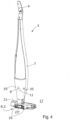
- Fig. 4 illustrates the vacuum cleaner 3 of the vacuum cleaner assembly 1, illustrated in Fig. 1 .
- the vacuum cleaner 3 comprises wheels 19 arranged at the second end 8.2 of the vacuum cleaner 3.
- the floor cleaning nozzle 21 is hinged in relation to the elongated body 7 in an axis coinciding with a rotational axis of the wheels 19.
- a user may hold the handle portion 4 of the vacuum cleaner 3 and move the floor cleaning nozzle 21 along a floor surface 17.
- the wheels 19 support the elongated body 7, as well as a portion of the floor cleaning nozzle 21.
- the wheels 19 can roll over the floor surface 17 and up into the charging dock 5 over the ramp portion 29.
- the charging dock 5 illustrated in Fig. 2 comprises a first magnetic attracting member 9 of the magnetic assembly 9, 9', illustrated in Fig. 1 .
- the vacuum cleaner 3 illustrated in Fig. 4 comprises a second magnetic attracting member 9' of the magnetic assembly 9, 9', illustrated in Fig. 1 .
- the second magnetic attracting member 9' illustrated in Fig. 4
- the second magnetic attracting member 9' will be pulled towards the first magnetic attracting member 9, illustrated in Fig. 2 , in a fixation direction fd.
- the first portion 11 of the vacuum cleaner 3, illustrated in Fig. 1 is fixated to the charging dock 5.
- the second fixating assembly 13, 13' comprises a second magnetic assembly 23, 23' configured to fixate the second portion 15 of the vacuum cleaner 3 to the charging dock 5.
- the charging dock 5 illustrated in Fig. 2 comprises a first magnetic attracting member 23 of the second magnetic assembly 23, 23'.
- the vacuum cleaner 3 illustrated in Fig. 4 comprises a second magnetic attracting member 23' of the second magnetic assembly 23, 23'.
- the second fixating assembly 13, 13' further comprises a recess 25.1 arranged in the base portion 18 of the charging dock 5.
- a portion of a wheel 19 illustrated in Fig. 4 is configured to extend into the recess 25.1, illustrated in Fig. 2 , when the vacuum cleaner 3 is in the charging dock 5.
- the second portion 15 of the vacuum cleaner 3 is further fixated to the charging dock 5, when the vacuum cleaner 3 is positioned therein.
- the second fixating assembly 13, 13' further comprises a protrusion 27.1 arranged at the base portion 18, in close proximity to the recess 25.1.
- a portion of a wheel 19 illustrated in Fig. 4 is configured to abut against the protrusion 27.1, illustrated in Fig. 2 .
- the second portion 15 of the vacuum cleaner 3 is further fixated to the charging dock 5, when the vacuum cleaner 3 is positioned therein.
- the second fixating assembly 13, 13' may comprise only one of, or only two of, the second magnetic assembly 23, 23', the recess 25.1, and the protrusion 27.1, or may, as is the case according to the illustrated embodiments, comprise the second magnetic assembly 23, 23', the recess 25.1, as well as the protrusion 27.1.
- the magnetic assembly 9, 9' is configured to fixate the first portion 11 of the vacuum cleaner 3 to the charging dock 5 in a fixation direction fd.
- the first contact units 33, 33' are each displaceably arranged in a second direction d2 being angled in relation to the fixation direction fd.
- the first contact units 33, 33' are each biased in a direction being angled in relation to a direction opposite the fixation direction fd. According to the illustrated embodiments, the angle a2 between the second direction d2 and the fixation direction fd is approximately 60 degrees.
- a portion of the wheel 19 of the vacuum cleaner 3 is configured to extend into the first recess 25.1, and the first protrusion 27.1 is configured to abut against a portion of the wheel 19, when the vacuum cleaner 3 is positioned in the charging dock 5.
- the second portion 15 of the vacuum cleaner 5 may be a portion of the at least one wheel 19.
Landscapes
- Engineering & Computer Science (AREA)
- Mechanical Engineering (AREA)
- Robotics (AREA)
- Electric Vacuum Cleaner (AREA)
- Electric Suction Cleaners (AREA)
Description
- The present invention relates to a vacuum cleaner assembly comprising a rechargeable stick type vacuum cleaner and a charging dock.
- Rechargeable stick type vacuum cleaners have become increasingly popular. Reasons for this might be that they are simple to use, require no power cord, and require little space when not in use. A rechargeable stick type vacuum cleaner is usually sold together with a charging dock in which the rechargeable stick type vacuum cleaner can be releasably positioned when not in use. The charging dock comprises a power cord configured to be connected to a power socket. The charging dock further comprises electrical contact units configured to abut against electrical contact units of the rechargeable stick type vacuum cleaner when the rechargeable stick type vacuum cleaner is positioned in the charging dock.
- Vacuum cleaner assemblies comprising a rechargeable stick type vacuum cleaner and a charging dock are associated with some problems. One problem is to provide a rigid and safe positioning of the vacuum cleaner in the charging dock. A vacuum cleaner assembly comprising a rechargeable stick type vacuum cleaner and a charging dock usually comprises a mechanical fixating assembly configured to fixate the vacuum cleaner to the charging dock when the vacuum cleaner is positioned therein. Some fixating assemblies comprise protrusions at the vacuum cleaner and grooves at the charging dock, or vice versa, wherein the protrusions are configured to extend into the grooves when the vacuum cleaner is positioned in the charging dock. Therefore, a user must usually lift the vacuum cleaner relative the charging dock, and align the protrusions relative the grooves when positioning the vacuum cleaner in the charging dock. This procedure is burdensome and requires attention from the user to align the protrusions relative the grooves.
- Likewise, when removing the vacuum cleaner from the charging dock, the user usually must lift the vacuum cleaner relative the charging dock in a certain direction, which is also burdensome and requires attention from the user to lift the vacuum cleaner in the correct direction. If the user lifts the vacuum cleaner in a direction differing from the correct direction, the charging dock will likely be displaced along a floor surface on which the charging dock is positioned, or will be lifted from the floor surface. The user will perceive both these situations negatively.
- Document
US2010242209 A discloses a vacuum cleaner assembly comprising a rechargeable stick type vacuum cleaner and a charging stand. - Document
WO 2016/206732 A1 discloses vacuum cleaner system comprising a vacuum cleaner having a battery and a charger (20) (26) for wireless changing of the battery. - Document
JP 2016 039860 A -
Document EP 3 195 778 A1 discloses a vacuum cleaner and a charging stand. - Document
CN 105 534 412 A discloses another vacuum cleaner and a stand. - It is an object of the present invention to overcome, or at least alleviate, at least some of the above-mentioned problems and drawbacks.
- According to a first aspect of the invention, the object is achieved by a vacuum cleaner assembly comprising a rechargeable stick type vacuum cleaner and a charging dock. The vacuum cleaner comprises an elongated body. The vacuum cleaner is configured to be releasably positioned in the charging dock such that the elongated body extends along a first direction. The assembly further comprises a magnetic assembly configured to fixate a first portion of the vacuum cleaner to the charging dock, and a second fixating assembly configured to fixate a second portion of the vacuum cleaner to the charging dock. The second portion is arranged a distance from the first portion along the first direction.
- As a result, a vacuum cleaner assembly is provided facilitating the positioning of the vacuum cleaner into the charging dock. Further, a vacuum cleaner assembly is provided being less dependent on the orientation direction of the vacuum cleaner when the vacuum cleaner is positioned in the charging dock. This because the assembly comprises the magnetic assembly configured to fixate the first portion of the vacuum cleaner to the charging dock, and the second fixating assembly configured to fixate the second portion of the vacuum cleaner to the charging dock. Thus, when positioning the vacuum cleaner in the charging dock, the user may simply grab the vacuum cleaner and position the second portion of the vacuum cleaner in the charging dock, and align the vacuum cleaner such that magnetic attracting members of the magnetic assembly are close to each other. The magnetic assembly will fixate the first portion of the vacuum cleaner to the charging dock, when the magnetic attracting members of the magnetic assembly are close to each other, such that the vacuum cleaner is positioned in the charging dock at a predetermined and safe position.
- Since the second portion is arranged a distance from the first portion along the first direction, a rigid and safe fixation is provided of the vacuum cleaner to the charging dock. Further, the fact that the second portion is arranged a distance from the first portion along the first direction facilitates removal of the vacuum cleaner from the charging dock. This because if a user wants to remove the vacuum cleaner from the charging dock, the user may simply grab the vacuum cleaner and apply a force onto the vacuum cleaner in a direction perpendicular to the first direction. As a result, a separation force between the magnetic attracting members of the magnetic assembly is obtained which causes a separation of the magnetic attracting members. When the magnetic attracting members are separated, the fixation of the first portion of the vacuum cleaner to the charging dock is released. Then the user may in a simple manner release the second portion of the vacuum cleaner from the charging dock to release the vacuum cleaner from the charging dock.
- Accordingly, a vacuum cleaner assembly is provided which provides a rigid and safe positioning of the vacuum cleaner in the charging dock, while the positioning of the vacuum cleaner in the charging dock is facilitated, and the removal of the vacuum cleaner from the charging dock is facilitated.
- Accordingly, a vacuum cleaner assembly is provided overcoming, or at least alleviating, at least some of the above-mentioned problems and drawbacks. As a result, the above-mentioned object is achieved.
- Optionally, the distance is greater than 5%, 10%, or 15% of a length of the vacuum cleaner in the first direction. Thereby, a rigid and safe fixation of the vacuum cleaner to the charging dock is ensured. In addition, a facilitated removal of the vacuum cleaner from the charging dock is ensured.
- Optionally, the charging dock is configured to be positioned on a floor surface, and wherein a plane comprising the first direction and the magnetic assembly is substantially perpendicular to the floor surface, when the charging dock is positioned on the floor surface. Thereby, a rigid and safe fixation is provided of the vacuum cleaner to the charging dock.
- Optionally, the vacuum cleaner comprises at least one wheel, and wherein the second portion is a portion of the at least one wheel. Thereby, an assembly is provided where the user may, when positioning the vacuum cleaner in the charging dock, position the at least one wheel relative the charging dock, and then aligning the vacuum cleaner such that magnetic attracting members of the magnetic assembly are close to each other. The positioning of the at least one wheel relative the charging dock may for example be performed by rolling the at least one wheel over a portion of the charging dock. As a result, a safe and simple fixation of the vacuum cleaner to the charging dock is provided, and a vacuum cleaner assembly is provided which further facilitates the positioning of, as well as the removal of, the vacuum cleaner.
- Optionally, the vacuum cleaner comprises a floor cleaning nozzle, and wherein the second portion is a portion of the floor cleaning nozzle. Thereby, an assembly is provided where the user may, when positioning the vacuum cleaner in the charging dock, position the floor cleaning nozzle relative the charging dock, and then align the vacuum cleaner such that magnetic attracting members of the magnetic assembly are close to each other. As a result, a safe and simple fixation is provided of the vacuum cleaner to the charging dock, and a vacuum cleaner assembly is provided which further facilitates the positioning of the vacuum cleaner in the charging dock.
- Optionally, the second fixating assembly comprises at least one protrusion. Thereby, a safe and simple fixation of the vacuum cleaner to the charging dock is provided.
- Optionally, the second fixating assembly comprises a protrusion arranged at the charging dock, and wherein the protrusion is configured to abut against the floor cleaning nozzle when the vacuum cleaner is releasably positioned in the charging dock. Thereby, an assembly is provided where the user may, when positioning the vacuum cleaner in the charging dock, position the floor cleaning nozzle such that the protrusion is abutting against the floor cleaning nozzle, and then align the vacuum cleaner such that magnetic attracting members of the magnetic assembly are close to each other. As a result, a safe and simple fixation is provided of the vacuum cleaner to the charging dock, and a vacuum cleaner assembly is provided which further facilitates the positioning of the vacuum cleaner in the charging dock.
- Optionally, the second fixating assembly comprises at least one recess. Thereby, a safe and simple fixation of the vacuum cleaner to the charging dock is provided.
- Optionally, the second fixating assembly comprises a recess arranged in the floor cleaning nozzle, and wherein the charging dock comprises a protrusion configured to extend into the recess when the vacuum cleaner is releasably positioned in the charging dock. Thereby, an assembly is provided where the user may, when positioning the vacuum cleaner in the charging dock, position the floor cleaning nozzle such that the protrusion extends into the recess, and then align the vacuum cleaner such that magnetic attracting members of the magnetic assembly are close to each other. As a result, a safe and simple fixation of the vacuum cleaner to the charging dock is provided, and a vacuum cleaner assembly is provided which further facilitates the positioning of the vacuum cleaner in the charging dock.
- Optionally, the second fixating assembly comprises a second magnetic assembly. Thereby, an assembly is provided where the user may, when positioning the vacuum cleaner in the charging dock, position the vacuum cleaner relative the charging dock such that one of the first and second magnet assemblies engages, and then align the vacuum cleaner relative the charging dock such that the other one of the first and second magnet assemblies engages.
- Thus, a vacuum cleaner assembly is provided which further facilitates the positioning of the vacuum cleaner in the charging dock. Further, an assembly is provided where the user may position the vacuum cleaner into the charging dock simply by displacing the vacuum cleaner in a direction perpendicular to the first direction. As a result, a still simpler positioning of the vacuum cleaner in the charging dock can be provided.
- Further, an assembly is provided further facilitating removal of the vacuum cleaner from the charging dock. This because a user wanting to remove the vacuum cleaner from the charging dock may simply grab the vacuum cleaner and apply a force onto the vacuum cleaner in a direction perpendicular to the first direction. As a result, a separation force is obtained between magnetic attracting members of one of the first and second the magnetic assemblies which causes a separation of these magnetic attracting members. When these magnetic attracting members are separated, the fixation of one portion of the vacuum cleaner to the charging dock is released. Then the user may in a simple manner release the fixation force between the other one of the first and second the magnetic assemblies, for example by applying a force onto the vacuum cleaner in the first direction to release the vacuum cleaner from the charging dock.
- Optionally, the charging dock is configured to be positioned on a floor surface, wherein the charging dock comprises a ramp portion, and wherein the ramp portion is adjacent to the floor surface when the charging dock is positioned on the floor surface. Thereby, an assembly is provided further facilitating the positioning of the vacuum cleaner into the charging dock. This because the user may, when positioning the vacuum cleaner in the charging dock, use the ramp to displace a portion of the vacuum cleaner into the charging dock. For example, the user may use the ramp to displace a wheel of the vacuum cleaner, and/or a floor cleaning nozzle of the vacuum cleaner, into the charging dock.
- Optionally, the ramp portion comprises a ramp surface, and wherein an angle between the ramp surface and the floor surface is less than 20 degrees. Thereby, an assembly is provided further facilitating the positioning of the vacuum cleaner into the charging dock.
- Optionally, the charging dock comprises first contact units and the vacuum cleaner comprises second contact units configured to abut against the first contact units, when the vacuum cleaner is releasably positioned in the charging dock, and wherein at least one of the first and second contacts units are displaceably arranged. Thereby, an assembly is provided further facilitating the positioning of the vacuum cleaner into the charging dock. Further, electrical contact is further ensured between contact units of the first contact units and contact units of the second contact units.
- Optionally, the magnetic assembly is configured to fixate the first portion of the vacuum cleaner to the charging dock in a fixation direction, and wherein at least one of the first and second contacts units are displaceably arranged in a second direction being angled in relation to the fixation direction. Thereby, an assembly is provided further facilitating the positioning of the vacuum cleaner into the charging dock. This because when the vacuum cleaner is positioned in the charging dock such that magnetic attracting members of the magnetic assembly are close to each other, the attracting force between the magnetic attracting members will displace at least one of the first and second contacts units at an angle separated from the fixation direction. Thereby, the at least one of the first and second contacts units can be displaced with a greater force than the attracting force of the magnetic attracting members. As a result, the positioning of the vacuum cleaner into the charging dock is further facilitated.
- Further, since at least one of the first and second contacts units are displaceably arranged in a second direction being angled in relation to the fixation direction, a more rigid and a safer fixation of the vacuum cleaner is provided. This because an abutting force between the at least one of the first and second contacts units and another contact unit will be angled in relation to the fixation direction, and will as a result thereof have a low impact on the attracting force, i.e. the fixation force, between the magnetic attracting members of the magnet assembly.
- Optionally, an angle between the second direction and the fixation direction is within the interval 15 - 90 degrees. Thereby, an assembly is provided further facilitating the positioning of the vacuum cleaner into the charging dock, and ensuring a more rigid and a safer fixation of the vacuum cleaner in the charging dock.
- Optionally, the fixation direction is substantially perpendicular to the first direction. As a result, a vacuum cleaner assembly is provided further facilitating the positioning of the vacuum cleaner into the charging dock. This because when positioning the vacuum cleaner in the charging dock, the user may simply displace the first portion of the vacuum cleaner in a direction perpendicular to the first direction to align the vacuum cleaner such that magnetic attracting members of the magnetic assembly are close to each other. The magnetic assembly will fixate the first portion of the vacuum cleaner to the charging dock when the magnetic attracting members of the magnetic assembly are close to each other such that the vacuum cleaner is positioned in the charging dock at a predetermined and safe position.
- Further, since the fixation direction is substantially perpendicular to the first direction, a safe and rigid fixation of the vacuum cleaner is ensured.
- Optionally, the charging dock is configured to be positioned on a floor surface, and wherein the fixation direction and the second direction are substantially parallel to the floor surface. Thereby, a safe and rigid fixation of the vacuum cleaner is ensured. Further, a vacuum cleaner assembly is provided further facilitating the positioning of the vacuum cleaner into the charging dock. This because when positioning the vacuum cleaner in the charging dock, the user may simply displace the first portion of the vacuum cleaner in a direction perpendicular to the first direction to align the vacuum cleaner such that magnetic attracting members of the magnetic assembly are close to each other. The magnetic assembly will fixate the first portion of the vacuum cleaner to the charging dock when the magnetic attracting members of the magnetic assembly are close to each other such that the vacuum cleaner is positioned in the charging dock at a predetermined and safe position. Further, the attracting force between magnetic attracting members of the magnetic assembly may ensure electrical contact between contact units, and may ensure displacement of at least one contact unit.
- Further, a vacuum cleaner assembly is provided further facilitating removal of the vacuum cleaner from the charging dock. This because a user wanting to remove the vacuum cleaner from the charging dock may simply grab the vacuum cleaner and apply a force onto the vacuum cleaner in a direction perpendicular to the first direction. As a result, a separation force between the magnetic attracting members of the magnetic assembly is obtained, which causes a separation of the magnetic attracting members. When the magnetic attracting members are separated, the fixation of the first portion of the vacuum cleaner to the charging dock is released. Then the user may in a simple manner release the second portion of the vacuum cleaner from the charging dock to release the vacuum cleaner from the charging dock.
- Optionally, at least one of the first contact units, and the second contact units, are dome-shaped. Thereby, a vacuum cleaner assembly is provided being further less dependent on the orientation direction of the vacuum cleaner when the vacuum cleaner is positioned in the charging dock. In addition, displacement of at least one of the first and second contacts units may be facilitated during positioning of the vacuum cleaner into the charging dock.
- Further features of, and advantages with, the present invention will become apparent when studying the appended claims and the following detailed description.
- Various aspects of the invention, including its particular features and advantages, will be readily understood from the example embodiments discussed in the following detailed description and the accompanying drawings, in which:
-
Fig. 1 illustrates a vacuum cleaner assembly, according to some embodiments, -
Fig. 2 illustrates a charging dock of the vacuum cleaner assembly, illustrated inFig. 1 , -
Fig. 3 illustrates a cross section of a ramp portion of the charging dock illustrated inFig. 2 , -
Fig. 4 illustrates the vacuum cleaner of the vacuum cleaner assembly, illustrated inFig. 1 , and -
Fig. 5 illustrates a cross section of a vacuum cleaner assembly, according to some further embodiments. - Aspects of the present invention will now be described more fully. Like numbers refer to like elements throughout. Well-known functions or constructions will not necessarily be described in detail for brevity and/or clarity.
-
Fig. 1 illustrates a vacuumcleaner assembly 1, according to some embodiments. Thevacuum cleaner assembly 1 comprises a rechargeable sticktype vacuum cleaner 3 and a chargingdock 5. For the reason of brevity and/or clarity, the rechargeable sticktype vacuum cleaner 3 is in some places herein referred to as "thevacuum cleaner 3". Thevacuum cleaner 3 comprises anelongated body 7, ahandle portion 4 arranged at a first end 8.1 of theelongated body 3, and afloor cleaning nozzle 21 arranged at a second end 8.2 of theelongated body 3. Thevacuum cleaner 3 further comprises a rechargeable battery, an electric motor, and an impeller. These components are not indicated inFig. 1 for the reason of brevity and/or clarity. The electric motor is configured to drive the impeller using energy stored in the rechargeable battery, when a button at thehandle portion 4 is pressed. The impeller is connected to thefloor cleaning nozzle 21 and to a filter unit of thevacuum cleaner 3. The impeller is configured to pump air from thefloor cleaning nozzle 21 through the filter unit in order to clean a surface, such as afloor surface 17. The rechargeable battery, the electric motor, the impeller, and the filter unit is arranged in theelongated body 7 between thehandle portion 4 and thefloor cleaning nozzle 21. - In
Fig. 1 , thevacuum cleaner 3 is releasably positioned in the chargingdock 5 such that theelongated body 7 extends along a first direction d1. Theassembly 1 comprises amagnetic assembly 9, 9' configured to fixate afirst portion 11 of thevacuum cleaner 3 to the chargingdock 5. Theassembly 1 further comprises a second fixating assembly 13, 13' configured to fixate asecond portion 15 of thevacuum cleaner 3 to the chargingdock 5. As illustrated inFig. 1 , thesecond portion 15 is arranged a distance d from thefirst portion 11 along the first direction d1. According to the illustrated embodiments, the distance d is approximately 17% of a length L of thevacuum cleaner 3 in the first direction d1. The length L of thevacuum cleaner 3 in the first direction d1 may be defined as the distance between the first end 8.1 of thevacuum cleaner 3 and the second end 8.2 of thevacuum cleaner 3, i.e. the distance between an outermost part of thehandle 4 in the first direction d1 and an outermost part of thefloor cleaning nozzle 21 in a direction opposite to the first direction d1. According to further embodiments, the distance d may be greater than 5%, 7%, 10%, 12% or 15% of a length L of thevacuum cleaner 3 in the first direction d1. Further, the distance d may, according to some embodiments, be within the interval of 5% - 70%, 7% - 60%, 8% - 50%, 10% - 40%, 12% - 35%, or 15% - 30% of the length L of thevacuum cleaner 3 in the first direction d1. Since thesecond portion 15 is arranged a distance d from thefirst portion 11 along the first direction d1, a safe and rigid fixation of thevacuum cleaner 1 in the chargingdock 5 is provided, and the positioning of thevacuum cleaner 3 into the chargingdock 5, as well as the removal of thevacuum cleaner 3 from the chargingdock 5, is facilitated, as is further explained herein. -
Fig. 2 illustrates the chargingdock 5 of thevacuum cleaner assembly 1, illustrated inFig. 1 . The chargingdock 5 comprises abase portion 18, anelongated portion 20, and asupport portion 22. Thebase portion 18 of the chargingdock 5 is configured to be positioned on afloor surface 17. Theelongated portion 20 connects thesupport portion 22 to thebase portion 18. Theelongated portion 20 extends in a direction substantially coinciding with the first direction d1. Thesupport portion 22 is configured to support thefirst portion 11 of thevacuum cleaner 3, illustrated inFig. 1 , as is further explained herein. - According to the embodiments illustrated in
Fig. 2 , the chargingdock 5 comprises aramp portion 29 arranged at thebase portion 18. Theramp portion 29 is adjacent to thefloor surface 17 when the chargingdock 5 is positioned on thefloor surface 17. Theramp portion 29 facilitates positioning of thevacuum cleaner 3, illustrated inFig. 1 , into the chargingdock 5, illustrated inFig. 2 . -
Fig. 3 illustrates a cross section of theramp portion 29 illustrated inFig. 2 . As illustrated, theramp portion 29 comprises aramp surface 31. According to the illustrated embodiments, an angle a1 between theramp surface 31 and thefloor surface 17 is approximately 19 degrees. According to further embodiments, the angle a1 between theramp surface 31 and thefloor surface 17 may be within an interval of 12 - 20 degrees, 14 - 20 degrees, 16 - 20 degrees, 17 - 20 degrees, or 18 - 20 degrees. Due to the small angle a1 between theramp surface 31 and thefloor surface 17, the positioning of thevacuum cleaner 3 into the chargingdock 5 is further facilitated. -
Fig. 4 illustrates thevacuum cleaner 3 of thevacuum cleaner assembly 1, illustrated inFig. 1 . According to the illustrated embodiments, thevacuum cleaner 3 compriseswheels 19 arranged at the second end 8.2 of thevacuum cleaner 3. Thefloor cleaning nozzle 21 is hinged in relation to theelongated body 7 in an axis coinciding with a rotational axis of thewheels 19. Thus, during cleaning, a user may hold thehandle portion 4 of thevacuum cleaner 3 and move thefloor cleaning nozzle 21 along afloor surface 17. Thewheels 19 support theelongated body 7, as well as a portion of thefloor cleaning nozzle 21. Further, when positioning thevacuum cleaner 3 into the chargingdock 5, illustrated inFig. 2 , thewheels 19 can roll over thefloor surface 17 and up into the chargingdock 5 over theramp portion 29. - The charging
dock 5 illustrated inFig. 2 comprises a first magnetic attractingmember 9 of themagnetic assembly 9, 9', illustrated inFig. 1 . Thevacuum cleaner 3 illustrated inFig. 4 comprises a second magnetic attracting member 9' of themagnetic assembly 9, 9', illustrated inFig. 1 . When the second magnetic attracting member 9', illustrated inFig. 4 , is close to the first magnetic attractingmember 9, illustrated inFig. 2 , the second magnetic attracting member 9' will be pulled towards the first magnetic attractingmember 9, illustrated inFig. 2 , in a fixation direction fd. As a result thereof, thefirst portion 11 of thevacuum cleaner 3, illustrated inFig. 1 , is fixated to the chargingdock 5. - Further, according to the embodiments illustrated in
Fig. 1 ,Fig. 2 , andFig. 4 , the second fixating assembly 13, 13' comprises a secondmagnetic assembly 23, 23' configured to fixate thesecond portion 15 of thevacuum cleaner 3 to the chargingdock 5. The chargingdock 5 illustrated inFig. 2 comprises a first magnetic attractingmember 23 of the secondmagnetic assembly 23, 23'. Thevacuum cleaner 3 illustrated inFig. 4 comprises a second magnetic attracting member 23' of the secondmagnetic assembly 23, 23'. When the second magnetic attracting member 23', illustrated inFig. 4 , is close to the first magnetic attractingmember 23, illustrated inFig. 2 , the second magnetic attracting member 23' will be pulled towards the first magnetic attractingmember 23, illustrated inFig. 2 , in the fixation direction fd. As a result thereof, thesecond portion 15 of thevacuum cleaner 3, illustrated inFig. 1 , is fixated to the chargingdock 5. - Further, according to the embodiments illustrated in
Fig. 1 ,Fig. 2 , andFig. 4 , the second fixating assembly 13, 13' further comprises a recess 25.1 arranged in thebase portion 18 of the chargingdock 5. A portion of awheel 19 illustrated inFig. 4 is configured to extend into the recess 25.1, illustrated inFig. 2 , when thevacuum cleaner 3 is in the chargingdock 5. As a result, thesecond portion 15 of thevacuum cleaner 3 is further fixated to the chargingdock 5, when thevacuum cleaner 3 is positioned therein. - In addition, according to the embodiments illustrated in
Fig. 1 ,Fig. 2 , andFig. 4 , the second fixating assembly 13, 13' further comprises a protrusion 27.1 arranged at thebase portion 18, in close proximity to the recess 25.1. A portion of awheel 19 illustrated inFig. 4 is configured to abut against the protrusion 27.1, illustrated inFig. 2 . As a result, thesecond portion 15 of thevacuum cleaner 3 is further fixated to the chargingdock 5, when thevacuum cleaner 3 is positioned therein. - According to some embodiments, the second fixating assembly 13, 13' may comprise only one of, or only two of, the second
magnetic assembly 23, 23', the recess 25.1, and the protrusion 27.1, or may, as is the case according to the illustrated embodiments, comprise the secondmagnetic assembly 23, 23', the recess 25.1, as well as the protrusion 27.1. - As indicated in
Fig. 2 , the chargingdock 5 comprisesfirst contact units 33, 33' arranged at the supportingportion 22 of the chargingdock 5. As indicated inFig. 4 , thevacuum cleaner 3 comprisessecond contact units 35, 35'. Thesecond contact units 35, 35' are configured to abut against thefirst contact units 33, 33', when thevacuum cleaner 3 is releasably positioned in the chargingdock 5. The chargingdock 5 is configured to charge the rechargeable battery of thevacuum cleaner 3, via the first andsecond contact units first contact units 33, 33' are each displaceably arranged in a second direction d2. For the reason of brevity and/or clarity, only one second direction d2 is indicated inFig. 2 . However, the contact unit 33' indicated with reference sign "33'" is also displaceable arranged in a second direction, corresponding to the second direction d2, as is further explained herein. Furthermore, thefirst contact units 33, 33' are each biased, e.g. spring biased, in a direction opposite to their respective second direction d2. - As mentioned, the
magnetic assembly 9, 9' is configured to fixate thefirst portion 11 of thevacuum cleaner 3 to the chargingdock 5 in a fixation direction fd. Thefirst contact units 33, 33' are each displaceably arranged in a second direction d2 being angled in relation to the fixation direction fd. In addition, thefirst contact units 33, 33' are each biased in a direction being angled in relation to a direction opposite the fixation direction fd. According to the illustrated embodiments, the angle a2 between the second direction d2 and the fixation direction fd is approximately 60 degrees. According to further embodiments, the angle a2 between the second direction d2 and the fixation direction fd may be within an interval of 15 - 90 degrees, 20 - 85 degrees, 30 - 80 degrees, 40 - 80 degrees, 45 - 75 degrees, 50 - 70 degrees, or 55 - 65 degrees. Since thefirst contact units 33, 33' each are displaceably arranged in a second direction d2 being angled in relation to the fixation direction fd, the attracting force between the magnetic attractingmembers 9, 9' of themagnetic assembly 9, 9' will displace thefirst contact units 33, 33' in directions d2 angled towards the fixation direction fd. Thereby, thefirst contact units 33, 33' can be displaced with a greater force than the attracting force between the magnetic attractingmembers 9, 9'. As a result, the positioning of thevacuum cleaner 3 into the chargingdock 5 is further facilitated. As a further result, a more rigid and a safer fixation of thevacuum cleaner 3 is provided. This because an abutting force between the first andsecond contacts units members 9, 9' of themagnet assembly 9, 9'. - Further, according to the illustrated embodiments, the
first contact units 33, 33' are dome-shaped. Thereby, the positioning of thevacuum cleaner 3 into the chargingdock 5 is facilitated. Further, the displacement of thefirst contact units 33, 33' in the second direction d2 is facilitated. According to further embodiments, thesecond contact units 35, 35' of thevacuum cleaner 3, illustrated inFig. 4 , may be displaceably arranged and may be dome-shaped. - As indicated in
Fig. 2 , according to the illustrated embodiments, the fixation direction fd is substantially perpendicular to the first direction d1. Further, the fixation direction fd and the second direction d2 are substantially parallel to thefloor surface 17. A plane p comprising the first direction d1 and the first magnetic attractingmember 9 of themagnetic assembly 9, 9' is substantially perpendicular to thefloor surface 17, when the chargingdock 5 is positioned on thefloor surface 17. Since the plane p comprises the first direction d1, thecontact unit 33 is also displaceably arranged in the second direction d2 at an angle a2 relative the plane p, and the contact unit 33' is displaceably arranged in a direction at an angle with the same size as the angle a2 relative the plane p, but on the opposite side of the plane p. - As mentioned, the plane p comprising the first direction d1 and the
magnetic assembly 9, 9' is substantially perpendicular to thefloor surface 17. According to some embodiments, a second plane comprising the first direction d1, which is perpendicular to the plane p1, may be angled in relation to thefloor surface 17 at an angle being within the interval of 0 - 20 degrees, 0 - 15 degrees, 0 - 10 degrees, or 0 - 5 degrees. - Further, according to the embodiments illustrated in
Fig. 1 andFig. 2 , thesupport portion 22 of the chargingdock 5 comprises a first support profile 22.1 and a second support profile 22.2. The first and second support profiles 22.1, 22.2 each extends from the plane p and is each provided with a bent shape in relation to the plane p. As a result, thesupport structure 22 supports thefirst portion 11 of thevacuum cleaner 3, illustrated inFig. 1 , also in directions perpendicular to the plane p. According to the illustrated embodiments, the first support structure 22.1 comprises acontact unit 33 of thefirst contact units 33, 33', and the second support structure 22.2 comprises another contact unit 33' of thefirst contact units 33, 33'. A surface normal of the first support structure 22.1 at the position of thecontact unit 33 is essentially opposite to the second direction d2. Likewise, a surface normal of the second support structure 22.2 at the position of the contact unit 33' is essentially opposite to the direction in which the contact unit 33' can be displaced. Further, according to the illustrated embodiments, the first magnetic attractingmember 9 of themagnetic assembly 9, 9' is arranged at thesupport portion 22, between the first and second support profiles 22.1, 22.2. As a result, when the second magnetic attracting member 9' of themagnetic assembly 9, 9', illustrated inFig. 4 is close to the first magnetic attractingmember 9, illustrated inFig. 2 , the second magnetic attractingmember 9 will be displaced towards the firstmagnetic member 9. Thereby, thefirst contact units 33, 33' will be displaced in an efficient manner. Further, the respective support structure 22.1, 22.2 will provide support of thefirst portion 11 of thevacuum cleaner 3, illustrated inFig. 4 . - One of the magnetic attracting
members 9, 9' of themagnet assembly 9, 9' may comprise a magnet producing a magnetic field, and the other magnetic attractingmember 9, 9' of themagnet assembly 9, 9' may comprise a ferromagnetic material, such that an attracting force is obtained between the magnetic attractingmembers 9, 9' when they are close to each other. As an alternative, both magnetic attractingmembers 9, 9' of themagnet assembly 9, 9' may comprise a magnet producing a magnetic field. According to such embodiments, they are oriented such that an attracting force is obtained between the magnetic attractingmembers 9, 9' when they are close to each other. Likewise, one of the magnetic attractingmembers 23, 23' of thesecond magnet assembly 23, 23' may comprise a magnet producing a magnetic field, and the other magnetic attractingmember 23, 23' of thesecond magnet assembly 23, 23' may comprise a ferromagnetic material, such that an attracting force is obtained between the magnetic attractingmembers 23, 23' when they are close to each other. As an alternative, both magnetic attractingmembers 23, 23' of thesecond magnet assembly 23, 23' may comprise a magnet producing a magnetic field. According to such embodiments, they are oriented such that an attracting force is obtained between the magnetic attractingmembers 23, 23' when they are close to each other. -
Fig. 5 illustrates a cross section of a vacuumcleaner assembly 1, according to some further embodiments. According to these embodiments, the second fixating assembly 13, 13' comprises a first protrusion 27.1, a second protrusion 27.2, and a third protrusion 27.3, each arranged at thebase portion 18 of the chargingdock 5. Further, according to these embodiments, the second fixating assembly 13, 13' comprises a first recess 25.1 arranged in thebase portion 18 of the chargingdock 5, and a second recess 25.2 arranged in thefloor cleaning nozzle 21. - A portion of the
wheel 19 of thevacuum cleaner 3 is configured to extend into the first recess 25.1, and the first protrusion 27.1 is configured to abut against a portion of thewheel 19, when thevacuum cleaner 3 is positioned in the chargingdock 5. Thus, according to these embodiments, as well as other embodiments described herein, thesecond portion 15 of thevacuum cleaner 5 may be a portion of the at least onewheel 19. - Further, according to the illustrated embodiments, the third protrusion 27.3 of the charging
dock 5 is configured to extend into the recess 25.2 arranged in thefloor cleaning nozzle 21, when thevacuum cleaner 3 is positioned in the chargingdock 5. In addition, the second protrusion 27.2 of the chargingdock 5 is configured to abut against a front part pf thefloor cleaning nozzle 21, when thevacuum cleaner 3 is positioned in the chargingdock 5. Due to these features, a further rigid and secure positioning of thevacuum cleaner 3 in the chargingdock 5 is provided. Thus, according to these embodiments, as well as other embodiments described herein, thesecond portion 15 of thevacuum cleaner 5 may, as an alternative to thewheel 19, or in addition to thewheel 19, be a portion of thefloor cleaning nozzle 21. According to some embodiments, one or more of the first protrusion 27.1, the second protrusion 27.2 and the third protrusion 27.3 may be displaceably arranged in relation to thebase portion 18 of the chargingdock 5 to facilitate removal of thevacuum cleaner 3 from the chargingdock 5, and/or to facilitate positioning of thevacuum cleaner 3 in the chargingdock 5. - According to some embodiments, the second fixating assembly 13, 13' may comprise only one of, only two of, or only three of the first recess 25.1, the first protrusion 27.1, the second protrusion 27.2 and the second recess 25.2, and the third recess 25.3. Further, the second fixating assembly 13, 13' of the embodiments illustrated in
Fig. 5 , may comprise a secondmagnetic assembly 23, 23', as described with reference to the embodiments illustrated inFig. 1 ,Fig. 2 , andFig. 4 , as an alternative to, or in addition to, one or more of the first recess 25.1, the first protrusion 27.1, the second protrusion 27.2 and the second recess 25.2, and the third recess 25.3. - It is to be understood that the foregoing is illustrative of various example embodiments and that the invention is defined only by the appended claims. A person skilled in the art will realize that the example embodiments may be modified, and that different features of the example embodiments may be combined to create embodiments other than those described herein, without departing from the scope of the present invention, as defined by the appended claims.
- As used herein, the term "comprising" or "comprises" is open-ended, and includes one or more stated features, elements, steps, components or functions but does not preclude the presence or addition of one or more other features, elements, steps, components, functions or groups thereof.
Claims (18)
- A vacuum cleaner assembly (1) comprising:- a rechargeable stick type vacuum cleaner (3), and- a charging dock (5),characterised in that the assembly (1) further comprises:wherein the vacuum cleaner (3) comprises an elongated body (7), and wherein the vacuum cleaner (3) is configured to be releasably positioned in the charging dock (5) such that the elongated body (7) extends along a first direction (d1),wherein the assembly (1) further comprises:- a magnetic assembly (9, 9') configured to fixate a first portion (11) of the vacuum cleaner (3) to the charging dock (5),- a second fixating assembly (13, 13') configured to fixate a second portion (15) of the vacuum cleaner (3) to the charging dock (5),and wherein the second portion (15) is arranged a distance (d) from the first portion (11) along the first direction (d1).
- The assembly (1) according to claim 1, wherein the distance (d) is greater than 5%, 10%, or 15% of a length (L) of the vacuum cleaner (3) in the first direction (d1).
- The assembly (1) according to claim 1 or 2, wherein the charging dock (5) is configured to be positioned on a floor surface (17), and wherein a plane (p) comprising the first direction (d1) and the magnetic assembly (9, 9') is substantially perpendicular to the floor surface (17), when the charging dock (5) is positioned on the floor surface (17).
- The assembly (1) according to any one of the preceding claims, wherein the vacuum cleaner (3) comprises at least one wheel (19), and wherein the second portion (15) is a portion of the at least one wheel (19).
- The assembly (1) according to any one of the preceding claims, wherein the vacuum cleaner (3) comprises a floor cleaning nozzle (21), and wherein the second portion (15) is a portion of the floor cleaning nozzle (21).
- The assembly (1) according to any one of the preceding claims, wherein the second fixating assembly (13, 13') comprises at least one protrusion (27.1, 27.2, 27.3).
- The assembly (1) according to claim 5 and 6, wherein the second fixating assembly (13, 13') comprises a protrusion (27.2, 27.3) arranged at the charging dock (5), and wherein the protrusion (27.2, 27.3) is configured to abut against the floor cleaning nozzle (21) when the vacuum cleaner (3) is releasably positioned in the charging dock (5).
- The assembly (1) according to any one of the preceding claims, wherein the second fixating assembly (13, 13') comprises at least one recess (25.1, 25.2).
- The assembly (1) according to claim 7 and 8, wherein the second fixating assembly (13, 13') comprises a recess (25.2) arranged in the floor cleaning nozzle (21), and wherein the charging dock (5) comprises a protrusion (27.3) configured to extend into the recess (25.2) when the vacuum cleaner (3) is releasably positioned in the charging dock (5).
- The assembly (1) according to any one of the preceding claims, wherein the second fixating assembly (13, 13') comprises a second magnetic assembly (23, 23').
- The assembly (1) according to any one of the preceding claims, wherein the charging dock (5) is configured to be positioned on a floor surface (17), wherein the charging dock (5) comprises a ramp portion (29), and wherein the ramp portion (29) is adjacent to the floor surface (17) when the charging dock (5) is positioned on the floor surface (17).
- The assembly (1) according to claim 11, wherein the ramp portion (29) comprises a ramp surface (31), and wherein an angle (a1) between the ramp surface (31) and the floor surface (17) is less than 20 degrees.
- The assembly (1) according to any one of the preceding claims, wherein the charging dock (5) comprises first contact units (33, 33') and the vacuum cleaner (3) comprises second contact units (35, 35') configured to abut against the first contact units (33, 33'), when the vacuum cleaner (3) is releasably positioned in the charging dock (5), and wherein at least one of the first and second contacts units (33, 33', 35, 35') are displaceably arranged.
- The assembly (1) according to claim 13, wherein the magnetic assembly (9, 9') is configured to fixate the first portion (11) of the vacuum cleaner (3) to the charging dock (5) in a fixation direction (fd), and wherein at least one of the first and second contacts units (33, 33', 35, 35') are displaceably arranged in a second direction (d2) being angled in relation to the fixation direction (fd).
- The assembly (1) according to claim 14, wherein an angle (a2) between the second direction (d2) and the fixation direction (fd) is within the interval 15 - 90 degrees.
- The assembly (1) according to claim 14 or 15, wherein the fixation direction (fd) is substantially perpendicular to the first direction (d1).
- The assembly (1) according to any one of the claims 14 - 16, wherein the charging dock (5) is configured to be positioned on a floor surface (17), and wherein the fixation direction (fd) and the second direction (d2) are substantially parallel to the floor surface (17).
- The assembly (1) according to any one of the claims 13 - 17, wherein at least one of the first contact units (33, 33') and the second contact units (35, 35') are dome-shaped.
Applications Claiming Priority (1)
| Application Number | Priority Date | Filing Date | Title |
|---|---|---|---|
| PCT/EP2017/082778 WO2019114964A1 (en) | 2017-12-14 | 2017-12-14 | Vacuum cleaner assembly |
Publications (2)
| Publication Number | Publication Date |
|---|---|
| EP3723569A1 EP3723569A1 (en) | 2020-10-21 |
| EP3723569B1 true EP3723569B1 (en) | 2025-07-02 |
Family
ID=60857058
Family Applications (1)
| Application Number | Title | Priority Date | Filing Date |
|---|---|---|---|
| EP17822232.9A Active EP3723569B1 (en) | 2017-12-14 | 2017-12-14 | Vacuum cleaner assembly |
Country Status (5)
| Country | Link |
|---|---|
| EP (1) | EP3723569B1 (en) |
| JP (1) | JP7069507B2 (en) |
| KR (1) | KR102454022B1 (en) |
| CN (1) | CN111386063B (en) |
| WO (1) | WO2019114964A1 (en) |
Families Citing this family (7)
| Publication number | Priority date | Publication date | Assignee | Title |
|---|---|---|---|---|
| JP7400349B2 (en) * | 2019-10-29 | 2023-12-19 | 三菱電機株式会社 | Vacuum cleaners and vacuum cleaner systems |
| CN111740478A (en) * | 2020-07-29 | 2020-10-02 | 小狗电器互联网科技(北京)股份有限公司 | Charging seat and cleaning device |
| CN215014391U (en) * | 2021-01-05 | 2021-12-07 | 北京石头世纪科技股份有限公司 | Cleaning equipment, storage device for cleaning equipment and cleaning system |
| CN113576320A (en) * | 2021-08-10 | 2021-11-02 | 苏州日新电器科技有限公司 | Dust catcher charging base and dust catcher subassembly |
| CN114569020A (en) * | 2022-02-14 | 2022-06-03 | 尚科宁家(中国)科技有限公司 | Use stable multi-functional surface cleaning machine |
| WO2024003811A1 (en) * | 2022-06-29 | 2024-01-04 | Dyson Technology Limited | Vacuum cleaner |
| SE2330232A1 (en) * | 2023-05-23 | 2024-11-24 | Electrolux Ab | Stick vacuum cleaner system |
Citations (16)
| Publication number | Priority date | Publication date | Assignee | Title |
|---|---|---|---|---|
| US4934020A (en) | 1989-01-09 | 1990-06-19 | Black & Decker Inc. | Charging unit and vacuum cleaner |
| JPH03272720A (en) | 1990-03-23 | 1991-12-04 | Mitsubishi Electric Corp | Vacuum cleaner |
| US5869947A (en) | 1995-01-13 | 1999-02-09 | Royal Appliance Mfg. Co. | Rechargeable hand held vacuum cleaner with electrical connections circuit board with spring contacts |
| JP2002085293A (en) | 2000-09-20 | 2002-03-26 | Twinbird Corp | Rechargeable vacuum cleaner |
| US20080040883A1 (en) | 2006-04-10 | 2008-02-21 | Jonas Beskow | Air Flow Losses in a Vacuum Cleaners |
| DE102010038095A1 (en) | 2010-10-11 | 2012-04-12 | Vorwerk & Co. Interholding Gmbh | Emptying station for accumulator-powered electric vacuum cleaner used in house, has electric vacuum cleaners that are connected to terminal portions of suction channel |
| JP2014176504A (en) | 2013-03-14 | 2014-09-25 | Toshiba Corp | Vacuum cleaner |
| CN204192519U (en) | 2014-09-11 | 2015-03-11 | 乐金电子(天津)电器有限公司 | The charging base of portable dust collector |
| US20160051109A1 (en) | 2014-08-21 | 2016-02-25 | Lg Electronics Inc. | Vacuum cleaner |
| JP2016039860A (en) | 2014-08-12 | 2016-03-24 | 三菱電機株式会社 | Rechargeable vacuum cleaner |
| CN105534412A (en) * | 2016-01-20 | 2016-05-04 | 江苏美的清洁电器股份有限公司 | Rechargeable dust collector assembly |
| WO2016114042A1 (en) | 2015-01-14 | 2016-07-21 | 三菱電機株式会社 | Electric vacuum cleaner |
| JP2016131633A (en) | 2015-01-16 | 2016-07-25 | 三菱電機株式会社 | Vacuum cleaner and cleaner system |
| JP2017029409A (en) | 2015-07-31 | 2017-02-09 | アイリスオーヤマ株式会社 | Vacuum cleaner |
| JP3210455U (en) | 2017-03-03 | 2017-05-25 | 株式会社ナカムラ | Vacuum cleaner storage stand |
| US20170202420A1 (en) | 2016-01-20 | 2017-07-20 | Jiangsu Midea Cleaning Appliances Co., Ltd. | Charging stand for vacuum cleaner |
Family Cites Families (11)
| Publication number | Priority date | Publication date | Assignee | Title |
|---|---|---|---|---|
| JP3801443B2 (en) | 2000-12-19 | 2006-07-26 | シャープ株式会社 | Vacuum cleaner |
| JP2004121469A (en) | 2002-10-01 | 2004-04-22 | Matsushita Electric Ind Co Ltd | Rechargeable vacuum cleaner |
| CN1751650A (en) * | 2005-09-22 | 2006-03-29 | 浙江大学 | Charging device for automatic vacuum cleaner, and connecting method therefor |
| DE102007036228B4 (en) * | 2007-08-02 | 2013-10-10 | BSH Bosch und Siemens Hausgeräte GmbH | Method and system for ensuring a connection between a mobile device and a stationary device, in particular between an accumulator-powered dust collection robot and a battery charging station |
| JP6121756B2 (en) | 2013-03-12 | 2017-04-26 | 東芝ライフスタイル株式会社 | Electric vacuum cleaner |
| EP3021727B1 (en) | 2013-07-18 | 2020-03-18 | Alfred Kärcher SE & Co. KG | Portable hard-surface-cleaning appliance |
| JP6435204B2 (en) * | 2015-01-28 | 2018-12-05 | 日立アプライアンス株式会社 | Electric vacuum cleaner |
| US20180303303A1 (en) * | 2015-06-24 | 2018-10-25 | Aktiebolaget Electrolux | Vacuum cleaner system |
| CA2971319A1 (en) * | 2016-01-20 | 2017-07-27 | Jiangsu Midea Cleaning Appliances Co., Ltd. | Vacuum cleaner |
| JP2017185122A (en) | 2016-04-08 | 2017-10-12 | 三菱電機株式会社 | Electric vacuum cleaner |
| CN206518524U (en) | 2016-12-01 | 2017-09-26 | 苏州尚垒电器有限公司 | Dust catcher charging base and dust suction device assembly |
-
2017
- 2017-12-14 CN CN201780097235.9A patent/CN111386063B/en active Active
- 2017-12-14 WO PCT/EP2017/082778 patent/WO2019114964A1/en not_active Ceased
- 2017-12-14 JP JP2020526572A patent/JP7069507B2/en not_active Expired - Fee Related
- 2017-12-14 EP EP17822232.9A patent/EP3723569B1/en active Active
- 2017-12-14 KR KR1020207016123A patent/KR102454022B1/en active Active
Patent Citations (16)
| Publication number | Priority date | Publication date | Assignee | Title |
|---|---|---|---|---|
| US4934020A (en) | 1989-01-09 | 1990-06-19 | Black & Decker Inc. | Charging unit and vacuum cleaner |
| JPH03272720A (en) | 1990-03-23 | 1991-12-04 | Mitsubishi Electric Corp | Vacuum cleaner |
| US5869947A (en) | 1995-01-13 | 1999-02-09 | Royal Appliance Mfg. Co. | Rechargeable hand held vacuum cleaner with electrical connections circuit board with spring contacts |
| JP2002085293A (en) | 2000-09-20 | 2002-03-26 | Twinbird Corp | Rechargeable vacuum cleaner |
| US20080040883A1 (en) | 2006-04-10 | 2008-02-21 | Jonas Beskow | Air Flow Losses in a Vacuum Cleaners |
| DE102010038095A1 (en) | 2010-10-11 | 2012-04-12 | Vorwerk & Co. Interholding Gmbh | Emptying station for accumulator-powered electric vacuum cleaner used in house, has electric vacuum cleaners that are connected to terminal portions of suction channel |
| JP2014176504A (en) | 2013-03-14 | 2014-09-25 | Toshiba Corp | Vacuum cleaner |
| JP2016039860A (en) | 2014-08-12 | 2016-03-24 | 三菱電機株式会社 | Rechargeable vacuum cleaner |
| US20160051109A1 (en) | 2014-08-21 | 2016-02-25 | Lg Electronics Inc. | Vacuum cleaner |
| CN204192519U (en) | 2014-09-11 | 2015-03-11 | 乐金电子(天津)电器有限公司 | The charging base of portable dust collector |
| WO2016114042A1 (en) | 2015-01-14 | 2016-07-21 | 三菱電機株式会社 | Electric vacuum cleaner |
| JP2016131633A (en) | 2015-01-16 | 2016-07-25 | 三菱電機株式会社 | Vacuum cleaner and cleaner system |
| JP2017029409A (en) | 2015-07-31 | 2017-02-09 | アイリスオーヤマ株式会社 | Vacuum cleaner |
| CN105534412A (en) * | 2016-01-20 | 2016-05-04 | 江苏美的清洁电器股份有限公司 | Rechargeable dust collector assembly |
| US20170202420A1 (en) | 2016-01-20 | 2017-07-20 | Jiangsu Midea Cleaning Appliances Co., Ltd. | Charging stand for vacuum cleaner |
| JP3210455U (en) | 2017-03-03 | 2017-05-25 | 株式会社ナカムラ | Vacuum cleaner storage stand |
Also Published As
| Publication number | Publication date |
|---|---|
| CN111386063B (en) | 2022-08-23 |
| EP3723569A1 (en) | 2020-10-21 |
| JP7069507B2 (en) | 2022-05-18 |
| KR20200097706A (en) | 2020-08-19 |
| KR102454022B1 (en) | 2022-10-12 |
| JP2021505222A (en) | 2021-02-18 |
| CN111386063A (en) | 2020-07-07 |
| WO2019114964A1 (en) | 2019-06-20 |
Similar Documents
| Publication | Publication Date | Title |
|---|---|---|
| WO2019114964A1 (en) | Vacuum cleaner assembly | |
| EP1565977A2 (en) | Improvements relating to retention of rechargeable devices | |
| US20100217263A1 (en) | Automated hair removal device | |
| US20140251701A1 (en) | High voltage converters for electrostatic applications | |
| EP3616674B1 (en) | Cpr device with quick disconnect locking system | |
| CN201994360U (en) | Power battery and battery seat thereof | |
| JP2019517867A (en) | Attachment for personal care device | |
| EP1384663A3 (en) | An aircraft handler | |
| EP3309001A1 (en) | Battery plug-in device for material handling equipment | |
| US6896468B2 (en) | Battery interchange system for battery powered floor maintenance equipment | |
| JP7508475B2 (en) | Stroller frames and strollers | |
| WO1998006471A1 (en) | Charger/launcher for fast recharge toy vehicle | |
| WO2024212970A1 (en) | Support, bearing member and seat assembly | |
| JP2025516982A (en) | Anti-slip device and plug assembly | |
| JPH06290831A (en) | Connector for charging electric vehicle | |
| KR101325904B1 (en) | Core recovering device | |
| CN118998225A (en) | Camping car and overrunning clutch structure thereof | |
| CN212484778U (en) | a guide sign | |
| CN210271403U (en) | Trolley for physical experiments | |
| KR101014470B1 (en) | Fixture of attachment for steering wheel and auxiliary handle | |
| CN110620415A (en) | Wireless charger is inhaled to trinity on-vehicle magnetism | |
| US20250383590A1 (en) | Rechargeable Photography Support Device | |
| CN217273365U (en) | Support part and support | |
| CN209692442U (en) | The permanent-magnet stator of starter | |
| CN212637033U (en) | An electric universal wheel and intelligent luggage |
Legal Events
| Date | Code | Title | Description |
|---|---|---|---|
| STAA | Information on the status of an ep patent application or granted ep patent |
Free format text: STATUS: UNKNOWN |
|
| STAA | Information on the status of an ep patent application or granted ep patent |
Free format text: STATUS: THE INTERNATIONAL PUBLICATION HAS BEEN MADE |
|
| PUAI | Public reference made under article 153(3) epc to a published international application that has entered the european phase |
Free format text: ORIGINAL CODE: 0009012 |
|
| STAA | Information on the status of an ep patent application or granted ep patent |
Free format text: STATUS: REQUEST FOR EXAMINATION WAS MADE |
|
| 17P | Request for examination filed |
Effective date: 20200714 |
|
| AK | Designated contracting states |
Kind code of ref document: A1 Designated state(s): AL AT BE BG CH CY CZ DE DK EE ES FI FR GB GR HR HU IE IS IT LI LT LU LV MC MK MT NL NO PL PT RO RS SE SI SK SM TR |
|
| AX | Request for extension of the european patent |
Extension state: BA ME |
|
| DAV | Request for validation of the european patent (deleted) | ||
| DAX | Request for extension of the european patent (deleted) | ||
| TPAC | Observations filed by third parties |
Free format text: ORIGINAL CODE: EPIDOSNTIPA |
|
| STAA | Information on the status of an ep patent application or granted ep patent |
Free format text: STATUS: EXAMINATION IS IN PROGRESS |
|
| 17Q | First examination report despatched |
Effective date: 20240314 |
|
| GRAP | Despatch of communication of intention to grant a patent |
Free format text: ORIGINAL CODE: EPIDOSNIGR1 |
|
| STAA | Information on the status of an ep patent application or granted ep patent |
Free format text: STATUS: GRANT OF PATENT IS INTENDED |
|
| INTG | Intention to grant announced |
Effective date: 20250205 |
|
| P01 | Opt-out of the competence of the unified patent court (upc) registered |
Free format text: CASE NUMBER: APP_17866/2025 Effective date: 20250411 |
|
| GRAS | Grant fee paid |
Free format text: ORIGINAL CODE: EPIDOSNIGR3 |
|
| GRAA | (expected) grant |
Free format text: ORIGINAL CODE: 0009210 |
|
| STAA | Information on the status of an ep patent application or granted ep patent |
Free format text: STATUS: THE PATENT HAS BEEN GRANTED |
|
| AK | Designated contracting states |
Kind code of ref document: B1 Designated state(s): AL AT BE BG CH CY CZ DE DK EE ES FI FR GB GR HR HU IE IS IT LI LT LU LV MC MK MT NL NO PL PT RO RS SE SI SK SM TR |
|
| REG | Reference to a national code |
Ref country code: GB Ref legal event code: FG4D |
|
| REG | Reference to a national code |
Ref country code: CH Ref legal event code: EP |
|
| REG | Reference to a national code |
Ref country code: DE Ref legal event code: R096 Ref document number: 602017090331 Country of ref document: DE |
|
| REG | Reference to a national code |
Ref country code: IE Ref legal event code: FG4D |
|
| REG | Reference to a national code |
Ref country code: NL Ref legal event code: MP Effective date: 20250702 |
|
| PG25 | Lapsed in a contracting state [announced via postgrant information from national office to epo] |
Ref country code: PT Free format text: LAPSE BECAUSE OF FAILURE TO SUBMIT A TRANSLATION OF THE DESCRIPTION OR TO PAY THE FEE WITHIN THE PRESCRIBED TIME-LIMIT Effective date: 20251103 |
|
| PG25 | Lapsed in a contracting state [announced via postgrant information from national office to epo] |
Ref country code: NL Free format text: LAPSE BECAUSE OF FAILURE TO SUBMIT A TRANSLATION OF THE DESCRIPTION OR TO PAY THE FEE WITHIN THE PRESCRIBED TIME-LIMIT Effective date: 20250702 |
|
| REG | Reference to a national code |
Ref country code: AT Ref legal event code: MK05 Ref document number: 1808246 Country of ref document: AT Kind code of ref document: T Effective date: 20250702 |
|
| PG25 | Lapsed in a contracting state [announced via postgrant information from national office to epo] |
Ref country code: IS Free format text: LAPSE BECAUSE OF FAILURE TO SUBMIT A TRANSLATION OF THE DESCRIPTION OR TO PAY THE FEE WITHIN THE PRESCRIBED TIME-LIMIT Effective date: 20251102 |
|
| PG25 | Lapsed in a contracting state [announced via postgrant information from national office to epo] |
Ref country code: NO Free format text: LAPSE BECAUSE OF FAILURE TO SUBMIT A TRANSLATION OF THE DESCRIPTION OR TO PAY THE FEE WITHIN THE PRESCRIBED TIME-LIMIT Effective date: 20251002 |
|
| REG | Reference to a national code |
Ref country code: LT Ref legal event code: MG9D |
|
| PG25 | Lapsed in a contracting state [announced via postgrant information from national office to epo] |
Ref country code: AT Free format text: LAPSE BECAUSE OF FAILURE TO SUBMIT A TRANSLATION OF THE DESCRIPTION OR TO PAY THE FEE WITHIN THE PRESCRIBED TIME-LIMIT Effective date: 20250702 |
|
| PG25 | Lapsed in a contracting state [announced via postgrant information from national office to epo] |
Ref country code: FI Free format text: LAPSE BECAUSE OF FAILURE TO SUBMIT A TRANSLATION OF THE DESCRIPTION OR TO PAY THE FEE WITHIN THE PRESCRIBED TIME-LIMIT Effective date: 20250702 |
|
| PG25 | Lapsed in a contracting state [announced via postgrant information from national office to epo] |
Ref country code: HR Free format text: LAPSE BECAUSE OF FAILURE TO SUBMIT A TRANSLATION OF THE DESCRIPTION OR TO PAY THE FEE WITHIN THE PRESCRIBED TIME-LIMIT Effective date: 20250702 |
|
| PGFP | Annual fee paid to national office [announced via postgrant information from national office to epo] |
Ref country code: FR Payment date: 20251223 Year of fee payment: 9 |
|
| PG25 | Lapsed in a contracting state [announced via postgrant information from national office to epo] |
Ref country code: GR Free format text: LAPSE BECAUSE OF FAILURE TO SUBMIT A TRANSLATION OF THE DESCRIPTION OR TO PAY THE FEE WITHIN THE PRESCRIBED TIME-LIMIT Effective date: 20251003 |
|
| PG25 | Lapsed in a contracting state [announced via postgrant information from national office to epo] |
Ref country code: SE Free format text: LAPSE BECAUSE OF FAILURE TO SUBMIT A TRANSLATION OF THE DESCRIPTION OR TO PAY THE FEE WITHIN THE PRESCRIBED TIME-LIMIT Effective date: 20250702 Ref country code: CZ Free format text: LAPSE BECAUSE OF FAILURE TO SUBMIT A TRANSLATION OF THE DESCRIPTION OR TO PAY THE FEE WITHIN THE PRESCRIBED TIME-LIMIT Effective date: 20250702 |
|
| PG25 | Lapsed in a contracting state [announced via postgrant information from national office to epo] |
Ref country code: LV Free format text: LAPSE BECAUSE OF FAILURE TO SUBMIT A TRANSLATION OF THE DESCRIPTION OR TO PAY THE FEE WITHIN THE PRESCRIBED TIME-LIMIT Effective date: 20250702 |
|
| PG25 | Lapsed in a contracting state [announced via postgrant information from national office to epo] |
Ref country code: BG Free format text: LAPSE BECAUSE OF FAILURE TO SUBMIT A TRANSLATION OF THE DESCRIPTION OR TO PAY THE FEE WITHIN THE PRESCRIBED TIME-LIMIT Effective date: 20250702 Ref country code: PL Free format text: LAPSE BECAUSE OF FAILURE TO SUBMIT A TRANSLATION OF THE DESCRIPTION OR TO PAY THE FEE WITHIN THE PRESCRIBED TIME-LIMIT Effective date: 20250702 |
|
| PG25 | Lapsed in a contracting state [announced via postgrant information from national office to epo] |
Ref country code: RS Free format text: LAPSE BECAUSE OF FAILURE TO SUBMIT A TRANSLATION OF THE DESCRIPTION OR TO PAY THE FEE WITHIN THE PRESCRIBED TIME-LIMIT Effective date: 20251002 |
|
| PG25 | Lapsed in a contracting state [announced via postgrant information from national office to epo] |
Ref country code: ES Free format text: LAPSE BECAUSE OF FAILURE TO SUBMIT A TRANSLATION OF THE DESCRIPTION OR TO PAY THE FEE WITHIN THE PRESCRIBED TIME-LIMIT Effective date: 20250702 |
|
| PG25 | Lapsed in a contracting state [announced via postgrant information from national office to epo] |
Ref country code: RO Free format text: LAPSE BECAUSE OF FAILURE TO SUBMIT A TRANSLATION OF THE DESCRIPTION OR TO PAY THE FEE WITHIN THE PRESCRIBED TIME-LIMIT Effective date: 20250702 |
|
| REG | Reference to a national code |
Ref country code: DE Ref legal event code: R026 Ref document number: 602017090331 Country of ref document: DE |
|
| PG25 | Lapsed in a contracting state [announced via postgrant information from national office to epo] |
Ref country code: SM Free format text: LAPSE BECAUSE OF FAILURE TO SUBMIT A TRANSLATION OF THE DESCRIPTION OR TO PAY THE FEE WITHIN THE PRESCRIBED TIME-LIMIT Effective date: 20250702 |
|
| PLBI | Opposition filed |
Free format text: ORIGINAL CODE: 0009260 |
|
| PG25 | Lapsed in a contracting state [announced via postgrant information from national office to epo] |
Ref country code: DK Free format text: LAPSE BECAUSE OF FAILURE TO SUBMIT A TRANSLATION OF THE DESCRIPTION OR TO PAY THE FEE WITHIN THE PRESCRIBED TIME-LIMIT Effective date: 20250702 |
|
| PGFP | Annual fee paid to national office [announced via postgrant information from national office to epo] |
Ref country code: DE Payment date: 20251229 Year of fee payment: 9 |
|
| PG25 | Lapsed in a contracting state [announced via postgrant information from national office to epo] |
Ref country code: IT Free format text: LAPSE BECAUSE OF FAILURE TO SUBMIT A TRANSLATION OF THE DESCRIPTION OR TO PAY THE FEE WITHIN THE PRESCRIBED TIME-LIMIT Effective date: 20250702 |
|
| REG | Reference to a national code |
Ref country code: CH Ref legal event code: L10 Free format text: ST27 STATUS EVENT CODE: U-0-0-L10-L00 (AS PROVIDED BY THE NATIONAL OFFICE) Effective date: 20260416 |
|
| PLAX | Notice of opposition and request to file observation + time limit sent |
Free format text: ORIGINAL CODE: EPIDOSNOBS2 |
|
| PG25 | Lapsed in a contracting state [announced via postgrant information from national office to epo] |
Ref country code: EE Free format text: LAPSE BECAUSE OF FAILURE TO SUBMIT A TRANSLATION OF THE DESCRIPTION OR TO PAY THE FEE WITHIN THE PRESCRIBED TIME-LIMIT Effective date: 20250702 Ref country code: SK Free format text: LAPSE BECAUSE OF FAILURE TO SUBMIT A TRANSLATION OF THE DESCRIPTION OR TO PAY THE FEE WITHIN THE PRESCRIBED TIME-LIMIT Effective date: 20250702 |
|
| 26 | Opposition filed |
Opponent name: DYSON TECHNOLOGY LIMITED Effective date: 20260401 |