EP3723384B1 - Communication network and related devices - Google Patents
Communication network and related devices Download PDFInfo
- Publication number
- EP3723384B1 EP3723384B1 EP18901396.4A EP18901396A EP3723384B1 EP 3723384 B1 EP3723384 B1 EP 3723384B1 EP 18901396 A EP18901396 A EP 18901396A EP 3723384 B1 EP3723384 B1 EP 3723384B1
- Authority
- EP
- European Patent Office
- Prior art keywords
- optical
- pon
- line terminal
- protocol
- interface
- Prior art date
- Legal status (The legal status is an assumption and is not a legal conclusion. Google has not performed a legal analysis and makes no representation as to the accuracy of the status listed.)
- Active
Links
- 238000004891 communication Methods 0.000 title claims description 83
- 230000003287 optical effect Effects 0.000 claims description 564
- 230000005540 biological transmission Effects 0.000 claims description 83
- 238000006243 chemical reaction Methods 0.000 claims description 43
- 238000011144 upstream manufacturing Methods 0.000 claims description 42
- 238000000034 method Methods 0.000 claims description 26
- 230000008569 process Effects 0.000 claims description 17
- 238000009432 framing Methods 0.000 claims description 16
- 239000013307 optical fiber Substances 0.000 description 25
- 238000005516 engineering process Methods 0.000 description 15
- 230000006855 networking Effects 0.000 description 15
- 238000010586 diagram Methods 0.000 description 13
- 230000006870 function Effects 0.000 description 13
- 230000008054 signal transmission Effects 0.000 description 7
- 238000007726 management method Methods 0.000 description 4
- 239000000835 fiber Substances 0.000 description 3
- 238000004590 computer program Methods 0.000 description 2
- RYGMFSIKBFXOCR-UHFFFAOYSA-N Copper Chemical compound [Cu] RYGMFSIKBFXOCR-UHFFFAOYSA-N 0.000 description 1
- 239000004606 Fillers/Extenders Substances 0.000 description 1
- 230000002776 aggregation Effects 0.000 description 1
- 238000004220 aggregation Methods 0.000 description 1
- 238000010276 construction Methods 0.000 description 1
- 229910052802 copper Inorganic materials 0.000 description 1
- 239000010949 copper Substances 0.000 description 1
- 238000013500 data storage Methods 0.000 description 1
- 230000001419 dependent effect Effects 0.000 description 1
- 239000004065 semiconductor Substances 0.000 description 1
Images


Classifications
-
- H—ELECTRICITY
- H04—ELECTRIC COMMUNICATION TECHNIQUE
- H04B—TRANSMISSION
- H04B10/00—Transmission systems employing electromagnetic waves other than radio-waves, e.g. infrared, visible or ultraviolet light, or employing corpuscular radiation, e.g. quantum communication
- H04B10/27—Arrangements for networking
- H04B10/272—Star-type networks or tree-type networks
-
- H—ELECTRICITY
- H04—ELECTRIC COMMUNICATION TECHNIQUE
- H04Q—SELECTING
- H04Q11/00—Selecting arrangements for multiplex systems
- H04Q11/0001—Selecting arrangements for multiplex systems using optical switching
- H04Q11/0062—Network aspects
- H04Q11/0067—Provisions for optical access or distribution networks, e.g. Gigabit Ethernet Passive Optical Network (GE-PON), ATM-based Passive Optical Network (A-PON), PON-Ring
-
- H—ELECTRICITY
- H04—ELECTRIC COMMUNICATION TECHNIQUE
- H04Q—SELECTING
- H04Q11/00—Selecting arrangements for multiplex systems
- H04Q11/0001—Selecting arrangements for multiplex systems using optical switching
- H04Q11/0062—Network aspects
- H04Q2011/0064—Arbitration, scheduling or medium access control aspects
-
- H—ELECTRICITY
- H04—ELECTRIC COMMUNICATION TECHNIQUE
- H04Q—SELECTING
- H04Q11/00—Selecting arrangements for multiplex systems
- H04Q11/0001—Selecting arrangements for multiplex systems using optical switching
- H04Q11/0062—Network aspects
- H04Q2011/009—Topology aspects
- H04Q2011/0096—Tree
Definitions
- This disclosure relates to the field of optical communications technologies, and the invention in particular relates to a communications network, an optical line terminal, and a method for processing optical signals in an optical line terminal.
- OAN optical Access Network
- a passive optical network (passive optical network, PON) is an implementation technology of the optical access network, and the PON is an optical access technology featuring point-to-multipoint transmission.
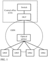
- a system architecture of the PON is shown in FIG. 1 .
- an optical line terminal (optical line terminal, OLT) is configured to provide a network side interface for an OAN.
- the OLT is connected to an upper-layer network side device (such as a switch or a router), and is connected to one or more lower-layer optical distribution networks (optical distribution network, ODN).
- the ODN includes a passive optical splitter configured for optical power distribution, a feeder fiber connecting the passive optical splitter to the OLT, and a distribution fiber connecting the passive optical splitter to an optical network unit (optical network unit, ONU).
- the ODN transmits downstream data of the OLT to each ONU by using the passive optical splitter.
- the ODN aggregates upstream data of the ONU and transmits the aggregated upstream data to the OLT.
- the ONU provides a user side interface for the OAN and is connected to the ODN. If the ONU further provides a user port function, for example, the ONU provides an Ethernet user port or a plain old telephone service (plain old telephone service, POTS) user port, the ONU is referred to as an optical network terminal (optical network terminal, ONT).
- ONT optical network terminal
- a conventional OLT is usually located in a central office (center office, CO), and the CO usually further includes a network side device.
- the PON network shown in FIG. 1 is applicable to a scenario in which the ONU and the ONT are deployed in an area such as a city close to the central office.
- CN 1855778 A discloses a passive optical network concatenating system and optical circuit terminal thereof.
- EP 2164221 A1 discloses a system, a method, and a device for passive optical network (PON) data transmission.
- US 20150373430 A1 discloses a frame conversion-based mid-span extender.
- the object of the present invention is to provide a communications network, an optical line terminal, and a method for processing optical signals in an optical line terminal, so that a broadband service can be accessed in a remote area, and transmission media can be saved and networking costs can be reduced.
- the first PON interface is connected to an upper-layer device of the optical line terminal, that is, the first optical line terminal; and the second PON interface is connected to a lower-layer device of the optical line terminal, that is, the customer-premises equipment.
- the first PON interface and the second PON interface are ports that are used for data connection in a communications network and for which a PON technology is used. Different PON technologies or a same PON technology may be used for the first PON interface and the second PON interface. In other words, the first PON interface and the second PON interface may correspond to different protocols or a same PON protocol.
- the optical line terminal needs to perform protocol conversion on the received optical signal for sending.
- This application provides the following two conversion manners:
- protocol conversion is directly performed on the optical signal.
- the processor is configured to: parse, by using a protocol corresponding to the first PON interface, the first optical signal received through the first PON interface, and encapsulate a parsed first optical signal by using a protocol corresponding to the second PON interface, to complete protocol conversion of the first optical signal.
- the processor is configured to: parse, by using the protocol corresponding to the second PON interface, the second optical signal received through the second PON interface, and encapsulate a parsed second optical signal by using the protocol corresponding to the first PON interface, to complete protocol conversion of the second optical signal.
- the optical line terminal may further include an optical module, a first PON MAC chip, and a second PON MAC chip.
- the first PON MAC chip uses a protocol corresponding to the first PON interface
- the second PON MAC chip uses a protocol corresponding to the second PON interface.
- the processor is specifically configured to: indicate the optical module to convert the first optical signal received through the first PON interface into a first electrical signal, indicate the first PON MAC chip to perform protocol deframing on the first electrical signal, indicate the second PON MAC chip to perform protocol framing on a first electrical signal obtained after protocol deframing, and indicate the optical module to perform electrical-to-optical conversion on a first electrical signal obtained after protocol framing, to obtain a processed first optical signal. Therefore, protocol conversion of the first optical signal is completed.
- the processor is specifically configured to: indicate the optical module to convert the second optical signal received through the second PON interface into a second electrical signal, indicate the second PON MAC chip to perform protocol deframing on the second electrical signal, indicate the first PON MAC chip to perform protocol framing on a second electrical signal obtained after protocol deframing, and indicate the optical module to perform electrical-to-optical conversion on a second electrical signal obtained after protocol framing, to obtain a processed second optical signal. Therefore, protocol conversion of the second optical signal is completed.
- the first PON interface and the second PON interface correspond to a same protocol.
- the optical line terminal may perform processing, for example, perform denoising and signal enhancement on the received optical signal through the processor, to improve signal transmission reliability.
- the communications apparatus is further configured with an Ethernet interface.
- the communications apparatus is further configured to receive, through the Ethernet interface, a first electrical signal sent by a network side device; the processor is further configured to convert the first electrical signal into a third optical signal; and the communications apparatus is further configured to send the third optical signal to the customer-premises equipment through the second PON interface.
- the communications apparatus is further configured to receive, through the second PON interface, a fourth optical signal sent by the customer-premises equipment; the processor is further configured to convert the fourth optical signal into a second electrical signal; and the communications apparatus is further configured to send the second optical signal to the network side device through the Ethernet interface.
- the optical line terminal in this application may be connected, through the first PON interface, to a device (for example, a conventional optical line terminal) that supports a downstream PON, and may be further connected to the network side device such as a switch or a router through the conventional Ethernet interface.
- a device for example, a conventional optical line terminal
- the network side device such as a switch or a router
- the optical line terminal in this application has more diversified application scenarios.
- the second optical line terminal is the optical line terminal provided above.
- the communications network further includes a first optical distribution network and a second optical distribution network.
- the first optical distribution network may provide an optical signal transmission path between the first optical line terminal and the second optical line terminal.
- the second optical distribution network may provide an optical signal transmission path between the second optical line terminal and the customer-premises equipment.
- the first optical distribution network may include at least one optical splitter
- the second optical distribution network may also include at least one optical splitter.
- the at least one optical splitter in the first optical distribution network may be configured to perform multi-level splitting processing on an optical signal sent by the first optical line terminal, and then send a processed optical signal to the second optical line terminal, where a quantity of levels is related to a quantity of optical splitters.
- the at least one optical splitter in the second optical distribution network may be configured to: perform multi-level splitting processing on an optical signal sent by the second optical line terminal, and then send a processed optical signal to the customer-premises equipment, where a quantity of levels is related to a quantity of optical splitters.
- optical splitter only one optical fiber may be used to enable connection to an upper-layer device in an optical distribution network. Then, a plurality of optical fibers are used starting from the optical fiber, to connect to lower-layer devices. Such a point-to-multipoint transmission mode can reduce transmission medium overheads and networking costs.
- a distance between the optical splitter and the second optical line terminal is less than a distance between the optical splitter and the first optical line terminal.
- the optical splitter is connected to the first optical line terminal in the upstream through one optical fiber, and is connected to a plurality of second optical line terminals in the downstream through a plurality of optical fibers. Therefore, when the optical splitter in the first distribution network is disposed at a location closer to the second optical line terminal, lengths of the plurality of optical fibers can be shortened, and networking costs can be reduced.
- a distance between the optical splitter and the customer-premises equipment is less than a distance between the optical splitter and the second optical line terminal.
- the optical splitter is connected to the second optical line terminal in the upstream through one optical fiber, and is connected to a plurality of customer-premises equipments in the downstream through a plurality of optical fibers. Therefore, when the optical splitter in the second optical distribution network is disposed at a location closer to the customer-premises equipment, lengths of the plurality of optical fibers can be shortened, and networking costs can be reduced.
- the communications network in this disclosure includes the first optical line terminal, the second optical line terminal, and the customer-premises equipment.
- the second optical line terminal is connected to a first optical line terminal at an upper layer through the PON interface, and is further connected to customer-premises equipment at a lower layer through the PON interface.
- the communications network in this application enables a user in a remote area to access a broadband service.
- the PON interface features point-to-multipoint transmission, and therefore transmission media can be saved and networking costs can be reduced.
- FIG. 2 is a structural diagram of a possible PON network in the prior art. As shown in FIG. 2 , OLT devices are not deployed in a central office, but deployed closer to devices such as ONTs or ONUs. The PON network shown in FIG. 2 may include more OLTs, to enable more users in a remote area to access a broadband service.
- a network side device is connected to the OLT through an Ethernet interface, and major transmission media include a network cable, an optical fiber, and the like. Because the Ethernet interface features point-to-point transmission, an independent transmission medium needs to be deployed between each OLT device and the network side device. However, due to a relatively large quantity of OLT devices, a large quantity of transmission media are required to deploy the PON network shown in FIG. 2 . Consequently, networking costs are high.
- this application provides a PON network and an optical line terminal, to provide the broadband service in the remote area.
- networking costs are low, and this application is easy to implement.
- a PON is a point-to-multipoint optical access technology.
- the PON interface is a port that is used for data connection in a communications network and for which the PON is used.
- a transmission medium connected to the PON interface is an optical fiber, and the PON interface may be configured to receive or send an optical signal.
- PONs there are many types of PONs, such as an asynchronous transfer mode PON (ATM passive optical network, APON), a broadband PON (broadband passive optical network, BPON), an Ethernet PON (ethernet passive optical network, EPON), a gigabit-capable PON (gigabit-capable passive optical network, GPON), and a 10 Gbit/s Ethernet PON (10G ethernet passive optical network, 10G EPON). Therefore, there may also be many types of PON interfaces, such as a GPON interface, an EPON interface, a symmetric 10G GPON interface, an asymmetric 10G GPON interface, a 10G EPON interface, a TWDM PON interface, and a future PON interface having a higher working rate.
- ATM passive optical network ATM passive optical network, APON
- BPON broadband passive optical network
- EPON Ethernet PON
- EPON gigabit-capable PON
- GPON gigabit-capable passive optical network
- a signal that can be identified by the PON interface and transmitted through the PON interface is a signal encapsulated by using a corresponding protocol. Therefore, if a device includes two PON interfaces of different types, protocol conversion processing needs to be performed on a signal received through one PON interface, and the signal can be sent through the other PON interface only after the signal is encapsulated by using a protocol corresponding to the other PON interface.
- a type of a PON interface identifies a type of an optical access technology used for the PON interface, and also identifies a protocol corresponding to the PON interface.
- the PON interface performs communication in a point-to-multipoint manner.
- the OLT is connected to customer-premises equipment through a PON interface, and may be connected to a plurality of ONTs through one PON interface.
- each PON interface may correspond to a plurality of customer-premises equipments.
- the split ratio is a concept specific to the PON interface and indicates a quantity of customer-premises equipments that may be with one PON interface.
- the split ratio indicates a quantity of customer-premises equipments that can be connected to one PON interface.
- a split ratio of a PON interface defined in an EPON standard is 1:32
- split ratios of a PON interface defined in a GPON standard are 1:32, 1:64, and 1:128.
- an EPON interface supports a maximum split ratio of 1:32.
- the EPON interface may output a maximum of 32 channels of optical signals, and the 32 channels of optical signals are transmitted to 32 different customer-premises equipments respectively.
- Ethernet is a most widely applied local area network communication mode and is also a protocol.
- An Ethernet interface (ethernet interface) is a port that is used for data connection in a network structure and for which the Ethernet protocol is used.
- the Ethernet interface may be configured to receive or send a signal, such as an Ethernet frame, for which the Ethernet protocol is used.
- the Ethernet interface mentioned in this application may include various types, for example, includes at least one of an SC fiber interface, an RJ-45 interface, an FDDI interface, an AUI interface, a BNC interface, or a console interface.
- Transmission media connected to the Ethernet interface may include a coaxial cable, a twisted pair, an optical fiber, and the like.
- the Ethernet interface performs communication in a point-to-point manner.
- a switch is connected to the OLT through an Ethernet interface.
- the switch needs to be connected to different OLTs through different Ethernet interfaces.
- each Ethernet interface corresponds to only one OLT.
- FIG. 3 is a schematic diagram of a hardware structure of an optical line terminal 300 according to this application.
- the optical line terminal 300 mainly includes a processor 101, a memory 102, a communications apparatus 103, and a power management module 104.
- the power management module 104 is configured to provide a stable current for the optical line terminal 300.
- the communications apparatus 103 may be configured for communication between the optical line terminal 300 and another communications device, for example, a network side device, another optical line terminal, or customer-premises equipment.
- the communications apparatus is configured with a first PON interface and a second PON interface.
- the first PON interface is configured for optical communication between the optical line terminal 300 and an upper-layer device (another optical line terminal at an upper layer).
- the second PON interface is configured for optical communication between the optical line terminal 300 and the customer-premises equipment.
- the first PON interface and the second PON interface are ports using a PON (passive optical network) technology for connection.
- the first PON interface may include at least one of a GPON interface, an EPON interface, a symmetric 10G GPON interface, an asymmetric 10G GPON interface, a 10G EPON interface, a TWDM PON interface, or a future PON interface having a higher working rate.
- the second PON interface may include at least one of a GPON interface, an EPON interface, a symmetric 10G GPON interface, an asymmetric 10G GPON interface, a 10G EPON interface, a TWDM PON interface, or a future PON interface having a higher working rate.
- the first PON interface and the second PON interface may be PON interfaces of different types, or may be PON interfaces of a same type.
- the following describes functions of modules in the optical line terminal 300 in different cases.
- the first PON interface and the second PON interface may be PON interfaces of different types.
- the processor 101 is configured to perform protocol conversion processing on an optical signal that is received through the first PON interface or the second PON interface, so that a processed optical signal is adapted to the second PON interface or the first PON interface. Two conversion manners are described below.
- protocol conversion is directly performed on the optical signal.
- the processor 101 is configured to: parse, by using a protocol corresponding to the first PON interface, a first optical signal received through the first PON interface, and encapsulate a parsed first optical signal by using a protocol corresponding to the second PON interface, to complete protocol conversion of the first optical signal.
- the processor 101 is configured to: parse, by using the protocol corresponding to the second PON interface, a second optical signal received through the second PON interface, and encapsulate a parsed second optical signal by using the protocol corresponding to the first PON interface, to complete protocol conversion of the second optical signal.
- the optical line terminal 300 may further include an optical module 105, a first PON MAC chip 106, and a second PON MAC chip 107.
- the first PON MAC chip 106 uses a protocol corresponding to the first PON interface
- the second PON MAC chip uses a protocol corresponding to the second PON interface.
- the processor 101 is specifically configured to: indicate the optical module 105 to convert a first optical signal received through the first PON interface into a first electrical signal, indicate the first PON MAC chip 106 to perform protocol deframing on the first electrical signal, indicate the second PON MAC chip 107 to perform protocol framing on a first electrical signal obtained after protocol deframing, and indicate the optical module 105 to perform electrical-to-optical conversion on a first electrical signal obtained after protocol framing, to obtain a processed first optical signal. In this way, protocol conversion of the first optical signal is completed.
- the processor 101 is specifically configured to: indicate the optical module 105 to convert a second optical signal received through the second PON interface into a second electrical signal, indicate the second PON MAC chip 107 to perform protocol deframing on the second electrical signal, indicate the first PON MAC chip 106 to perform protocol framing on a second electrical signal obtained after protocol deframing, and indicate the optical module 105 to perform electrical-to-optical conversion on a second electrical signal obtained after protocol framing, to obtain a processed second optical signal. In this way, protocol conversion of the second optical signal is completed.
- the first PON interface and the second PON interface are PON interfaces of a same type.
- the optical line terminal may perform processing, for example, perform denoising and signal enhancement, on a received signal through the processor, to improve signal transmission reliability.
- the communications apparatus 103 may be further configured with an Ethernet interface.
- the Ethernet interface is an interface that performs communication by using an Ethernet protocol, and may be configured for communication between the optical line terminal 300 and an upper-layer network side device (a switch, a router, or the like).
- the memory 102 is coupled to the processor 101, and is configured to store various software programs and/or a plurality of sets of instructions.
- the memory 102 may include a high-speed random access memory, or may include a nonvolatile memory, for example, one or more disk storage devices, a flash memory device, or another nonvolatile solid-state storage device.
- the memory 102 may store an operating system (which is briefly referred to as a system below), for example, an embedded operating system such as Android, iOS, Windows, or Linux.
- the memory 102 may further store a network communications program.
- the network communications program may be used to communicate with one or more optical line terminals, one or more customer-premises equipments, or one or more network side devices.
- the processor 101 may be configured to: read and execute a computer-readable instruction; implement a function of managing the optical line terminal 300; parse, control, or process a packet received by the optical line terminal 300; and the like. Specifically, the processor 101 may be configured to invoke a program stored in the memory 102, and execute an instruction included in the program. The instruction may be used for implementing a function of signal transmission of the optical line terminal 300 in a PON communications network.
- the optical line terminal 300 may further include an upstream board, a backplane that provides a physical connection for each unit, a clock, a fan, a fan control module, and the like. Details are not described herein.
- optical line terminal 300 shown in FIG. 3 is only an implementation of this application. In actual application, the optical line terminal 300 may alternatively include more or fewer components, and this is not limited herein.
- the optical line terminal 300 may be connected, through the first PON interface, to a device (for example, a conventional optical line terminal) that supports a downstream PON, or may be connected to a network side device such as a switch or a router through a conventional Ethernet interface.
- a device for example, a conventional optical line terminal
- a network side device such as a switch or a router
- the optical line terminal 300 in this application has more diversified application scenarios.
- optical line terminal there may be many actual forms of the optical line terminal.
- the optical line terminal 300 may be implemented in a form of a box-type device or an integrated device.
- the optical line terminal includes one or more PON MAC chips configured to process a communication service between the optical line terminal and an upper-layer device.
- the PON MAC chip is configured to implement a function of PON media access control (media access control, MAC) layer protocol processing.
- the optical line terminal further includes a component or chip configured to implement a forwarding function.
- the component or chip may be configured to implement local area network switch (LAN switch, LSW) forwarding, network processing (network processing, NP), traffic management (traffic management, TM), or the like.
- LAN switch local area network switch
- LSW local area network switch
- NP network processing
- TM traffic management
- the optical line terminal further includes one or more PON MAC chips configured to process a communication service between the optical line terminal and a lower-layer device.
- the PON MAC chip is configured to implement a function of PON media access control (media access control, MAC) layer protocol processing.
- the optical line terminal may further include one or more ETH MACs/PHYs configured to process a communication service between the optical line terminal and an upper-layer device.
- the ETH MAC/PHY is configured to implement a function of Ethernet MAC layer protocol processing/Ethernet physical layer protocol processing during communication with the upper-layer device.
- the optical line terminal 300 may be further implemented in a form of a frame-type device.
- the optical line terminal may include one or more upstream access modules, one or more control modules, and one or more downstream access modules.
- the upstream access module provides a first PON interface.
- the downstream access module provides a second PON interface.
- the control module is configured to control the optical line terminal to implement a function of protocol processing, packet switching, packet forwarding, or the like.
- an upstream interface may further include a conventional Ethernet interface, to enable the optical line terminal to be applied to more optical communications scenarios.
- this application provides a communications network, to enable access to a broadband service in a remote area and to reduce networking costs during construction of the communications network.
- An optical line terminal includes a first PON interface used for communicating with an upper-layer device.
- the first PON interface may be used for point-to-multipoint communication between the upper-layer device and a plurality of optical line terminals. This can save transmission media and reduce networking costs.
- FIG. 6 is a schematic diagram of a structure of a communications network according to this application. The following separately describes devices, connections between the devices, deployment locations, a data transmission process, and the like in the communications network in this application with reference to FIG. 6 .
- the communications network includes a first optical line terminal, a second optical line terminal, and customer-premises equipment.
- the first optical line terminal is connected to at least one second optical line terminal through a PON interface
- the second optical line terminal is connected to at least one customer-premises equipment through a PON interface.
- the first optical line terminal is connected to the second optical line terminal through a PON interface
- the second optical line terminal is also connected to the customer-premises equipment through a PON interface
- transmission media are both optical fibers.
- the first optical line terminal and the second optical line terminal may be connected through a first optical distribution network
- the second optical line terminal and the customer-premises equipment may be connected through a second optical distribution network.
- the first optical distribution network may provide an optical signal transmission path between the first optical line terminal and the second optical line terminal.
- the second optical distribution network may provide an optical signal transmission path between the second optical line terminal and the customer-premises equipment.
- the first optical distribution network and the second optical distribution network each may be implemented as an intelligent ODN (iODN), an easy ODN (easy ODN), a smart ODN (smart ODN), or another type of ODN. This is not limited in this application.
- the first optical distribution network may include at least one optical splitter, and an optical fiber between the first optical line terminal and the second optical line terminal.
- the second optical distribution network may also include at least one optical splitter, and an optical fiber between the second optical line terminal and the customer-premises equipment.
- the optical splitter herein is a passive device, and is used for downstream data distribution and upstream data aggregation.
- the optical splitter has one upstream optical interface and several downstream optical interfaces. Optical signals from the upstream optical interface are distributed to all of the downstream optical interfaces for transmission. Optical signals from the downstream optical interfaces are aggregated to the unique upstream optical interface for transmission.
- the at least one optical splitter in the first optical distribution network may be configured to: perform multi-level splitting processing on an optical signal sent by the first optical line terminal, and then send a processed optical signal to the second optical line terminal, where a quantity of levels is related to a quantity of optical splitters.
- the at least one optical splitter in the second optical distribution network may be configured to: perform multi-level splitting processing on an optical signal sent by the second optical line terminal, and then send a processed optical signal to the customer-premises equipment, where a quantity of levels is related to a quantity of optical splitters.
- the first optical distribution network includes a first optical splitter
- the second optical distribution network includes a second optical splitter
- the first optical line terminal may be connected to a plurality of second optical line terminals, and the second optical line terminal may be further connected to a plurality of customer-premises equipments.
- the communications network shown in FIG. 6 or FIG. 7 enables access of more customer-premises equipments. This expands a service scope.
- a plurality of levels of second optical line terminals may be disposed.
- the first optical line terminal is connected to a plurality of second optical line terminals, and the second optical line terminal may be further connected to another second optical line terminal, and is connected to the customer-premises equipment after a plurality of levels of connections.
- a communications network shown in FIG. 8 enables access of more customer-premises equipments. This expands a service scope.
- the first optical line terminal provides a PON interface used for communicating with a lower-layer device (namely, the second optical line terminal).
- the first optical line terminal may be a conventional optical line terminal (namely, a conventional OLT), or may be the optical line terminal shown in FIG. 3 .
- the second optical line terminal provides not only a PON interface used for communicating with a lower-layer device (namely, the customer-premises equipment), but also a PON interface used for communicating with an upper-layer device (namely, the first optical line terminal).
- the first optical line terminal may be the optical line terminal 300 shown in FIG. 3 .
- the customer-premises equipment is a device that sends Ethernet data to a user or receives Ethernet data sent by a user, and may provide various broadband services for the user, such as internet surfing, VoIP, HDTV, and video conference.
- the customer-premises equipment may be a device such as an ONU or an ONT.
- the communications network shown in FIG. 6 is an optical access network
- the optical access network is connected to a core network
- a network side device is a device that is in the core network and that is directly connected to the optical access network.
- the network side device may be a switch, a router, or the like.
- the network side device is an important device in an optical communications network, and is generally disposed in a central office.
- both the first optical line terminal and the network side device may be disposed in the central office.
- the second optical line terminal may be disposed in a remote area relatively far away from the central office. Because the second optical line terminal is connected to lower-layer customer-premises equipment, the customer-premises equipment in this application may be deployed in a remote area such as a rural area relatively far away from a city, to enable access to a broadband service in the remote area.
- optical splitters may be disposed based on an existing standard. This is not limited in this application.
- the first optical line terminal and the second optical line terminal are connected through the first optical distribution network, and the first optical splitter is disposed in the first optical distribution network.
- a distance between the first optical splitter and the second optical line terminal is less than a distance between the first optical splitter and the first optical line terminal.
- the first optical splitter is disposed at a location closer to the second optical line terminal.
- the first optical splitter is connected to the first optical line terminal in the upstream through one optical fiber, and is connected to a plurality of second optical line terminals in the downstream through a plurality of optical fibers. Therefore, when the first optical splitter is disposed at the location closer to the second optical line terminal, lengths of the plurality of optical fibers can be shortened, and networking costs can be reduced.
- the plurality of optical splitters may be disposed based on an actual situation and the existing standard. This is not limited in this application.
- the second optical line terminal and the customer-premises equipment are connected through the second optical distribution network, and the second optical splitter is disposed in the second optical distribution network.
- a distance between the second optical splitter and the customer-premises equipment is less than a distance between the second optical splitter and the second optical line terminal.
- the second optical splitter is disposed at a location closer to the customer-premises equipment.
- the second optical splitter is connected to the second optical line terminal in the upstream through one optical fiber, and is connected to a plurality of customer-premises equipments in the downstream through a plurality of optical fibers. Therefore, when the second optical splitter is disposed at the location closer to the customer-premises equipment, lengths of the plurality of optical fibers can be shortened, and networking costs can be reduced.
- the plurality of optical splitters may be disposed based on an actual situation and the existing standard. This is not limited in this application.
- the data transmission process includes a downstream transmission process and an upstream transmission process.
- a downstream transmission process a signal is sent from the network side device to the customer-premises equipment.
- a signal is sent from the customer-premises equipment to the network side device. Descriptions are separately provided below.
- the downstream transmission process may include the following steps.
- the first optical signal may be obtained by converting an electrical signal received by the first optical line terminal.
- the electrical signal is sent by the network side device to the first optical line terminal through an Ethernet interface.
- the first optical line terminal is connected to the network side device through the Ethernet interface.
- the network side device sends an electrical signal to the first optical line terminal.
- the first optical line terminal performs protocol conversion on the received electrical signal, and performs electrical-to-optical conversion on an electrical signal obtained after protocol conversion, to obtain the first optical signal.
- the first optical line terminal sends, through a PON interface, the first optical signal to the at least one second optical line terminal connected to the first optical line terminal.
- the communications network further includes a first optical distribution network.
- the first optical signal sent by the first optical line terminal may be transmitted to the at least one second optical line terminal through the first optical distribution network.
- the first optical distribution network includes a first optical splitter, and the first optical signal sent by the first optical line terminal may be transmitted to the at least one second optical line terminal through the first optical distribution network by using the first optical splitter.
- the second optical line terminal processes the first optical signal.
- the second optical line terminal After receiving the first optical signal through a PON interface (for example, the first PON interface in FIG. 3 ) connected to an upper-layer device, the second optical line terminal performs protocol conversion processing on the first optical signal, so that a processed first optical signal is adapted to a PON interface connected to a lower-layer device.
- a PON interface for example, the first PON interface in FIG. 3
- the second optical line terminal sends the processed first optical signal to at least one customer-premises equipment.
- the second optical line terminal sends the processed first optical signal to the at least one customer-premises equipment through the PON interface (for example, the second PON interface in FIG. 3 ) connected to the lower-layer device.
- PON interface for example, the second PON interface in FIG. 3
- the communications network further includes a second optical distribution network.
- the processed first optical signal sent by the second optical line terminal may be transmitted to the at least one customer-premises equipment through the second optical distribution network.
- the second optical distribution network includes a second optical splitter
- the processed first optical signal sent by the second optical line terminal may be transmitted to the at least one customer-premises equipment through the second optical distribution network by using the second optical splitter.
- the customer-premises equipment may receive, based on identification information carried in the first optical signal, data belonging to the customer-premises equipment; and may further perform optical-to-electrical conversion on the data, and then transmit, to a terminal device (such as a computer) directly used by a user, data obtained after optical-to-electrical conversion.
- a terminal device such as a computer
- the data downstream transmission process is completed through the foregoing three steps.
- the downstream transmission process for functions of the devices, refer to detailed descriptions of the foregoing steps. Details are not described herein.
- the upstream transmission process may include the following steps.
- the second optical signal may be obtained by converting an electrical signal received by the customer-premises equipment.
- the electrical signal may be sent by a terminal device (such as a computer) directly used by a user to the customer-premises equipment through an Ethernet interface.
- the customer-premises equipment is connected to the terminal device through the Ethernet interface.
- the terminal device sends an electrical signal to the customer-premises equipment when the terminal device needs to send data to a network side.
- the customer-premises equipment performs protocol conversion on the received electrical signal, and performs electrical-to-optical conversion on an electrical signal obtained after protocol conversion, to obtain the second optical signal.
- the customer-premises equipment sends, through a PON interface, the second optical signal to the second optical line terminal connected to the customer-premises equipment.
- the communications network further includes a second optical distribution network.
- the second optical signal sent by the customer-premises equipment may be transmitted, through the second optical distribution network, to the second optical line terminal connected to the customer-premises equipment.
- the second optical distribution network includes a second optical splitter, and the second optical signal sent by the customer-premises equipment may be transmitted, through the second optical distribution network by using the second optical splitter, to the second optical line terminal connected to the customer-premises equipment.
- the second optical line terminal processes the second optical signal.
- the second optical line terminal is connected to a plurality of customer-premises equipments, and the second optical line terminal may receive a plurality of second optical signals.
- the plurality of second optical signals received by the second optical line terminal may be different.
- the second optical line terminal after receiving the second optical signal through a PON interface (for example, the second PON interface in FIG. 3 ) connected to a lower-layer device, the second optical line terminal performs protocol conversion processing on the second optical signal, so that a processed second optical signal is adapted to a PON interface connected to an upper-layer device.
- the second optical line terminal sends the processed second optical signal to the first optical line terminal.
- the second optical line terminal sends the processed second optical signal to the at least one customer-premises equipment through the PON interface (for example, the first PON interface in FIG. 3 ) connected to the upper-layer device.
- PON interface for example, the first PON interface in FIG. 3
- the communications network further includes a first optical distribution network.
- the processed second optical signal sent by the second optical line terminal may be transmitted to the first optical line terminal through the first optical distribution network.
- the first optical distribution network includes a first optical splitter
- the processed second optical signal sent by the second optical line terminal may be transmitted to the first optical line terminal through the first optical distribution network by using the first optical splitter.
- transmission may be performed in a time division multiplexing (TDM) mode.
- TDM time division multiplexing
- the first optical line terminal may further perform optical-to-electrical conversion on the second optical signal, and then transmit, to the network side device, an electrical signal obtained after optical-to-electrical conversion.
- the data upstream transmission process is completed through the foregoing three steps.
- the upstream transmission process for functions of the devices, refer to detailed descriptions of the foregoing steps. Details are not described herein.
- FIG. 11 is a functional block diagram of an optical line terminal according to this application.
- the optical line terminal may include a processing unit 111, a storage unit 112, and a communications unit 113.
- the communications unit 113 is configured with a first PON unit and a second PON unit.
- the communications unit 113 is configured to receive, through the first PON unit, a first optical signal sent by a first optical line terminal; the processing unit 111 is configured to process the first optical signal; and the communications unit 113 is further configured to send a processed first optical signal to customer-premises equipment through the second PON unit.
- the communications unit 113 is configured to receive, through the second PON unit, a second optical signal sent by the customer-premises equipment; the processing unit 111 is configured to process the second optical signal; and the communications unit 113 is further configured to send a processed second optical signal to the first optical line terminal through the first PON unit.
- optical line terminal shown in FIG. 11 may be implemented as the second optical line terminal in any one of FIG. 6 to FIG. 8 .
- functions of functional modules in the optical line terminal refer to FIG. 6 to FIG. 8 and related descriptions. Details are not described herein.
- the communications network in this application includes a first optical line terminal, a second optical line terminal, and customer-premises equipment.
- the second optical line terminal may be connected to a first optical line terminal at an upper layer through a PON interface, and may be further connected to customer-premises equipment at a lower layer through a PON interface.
- the communications network in this application enables a user in a remote area to access a broadband service.
- the PON interface features point-to-multipoint transmission, and therefore transmission media can be saved and networking costs can be reduced.
- All or some of the foregoing embodiments may be implemented by software, hardware, firmware, or any combination thereof.
- software is used to implement the embodiments, all or some of the embodiments may be implemented in a form of a computer program product.
- the computer program product includes one or more computer instructions. When the computer instructions are loaded and executed on a computer, all or some of the procedures or functions according to this application are generated.
- the computer may be a general-purpose computer, a dedicated computer, a computer network, or another programmable apparatus.
- the computer instructions may be stored in a computer-readable storage medium or may be transmitted from a computer-readable storage medium to another computer-readable storage medium.
- the computer instructions may be transmitted from a website, computer, server, or data center to another website, computer, server, or data center in a wired (for example, a coaxial cable, an optical fiber, or a digital subscriber line) or wireless (for example, infrared, radio, or microwave) manner.
- the computer-readable storage medium may be any usable medium accessible by a computer, or a data storage device, such as a server or a data center, integrating one or more usable media.
- the usable medium may be a magnetic medium (for example, a floppy disk, a hard disk, or a magnetic tape), an optical medium (for example, a DVD), a semiconductor medium (for example, a solid-state drive), or the like.
Description
- This disclosure relates to the field of optical communications technologies, and the invention in particular relates to a communications network, an optical line terminal, and a method for processing optical signals in an optical line terminal.
- Current broadband access technologies are mainly categorized into copper access technologies (for example, various DSL technologies) and optical access technologies. An access network implemented by using the optical access technology is referred to as an optical access network (Optical Access Network, OAN).
- A passive optical network (passive optical network, PON) is an implementation technology of the optical access network, and the PON is an optical access technology featuring point-to-multipoint transmission. A system architecture of the PON is shown in
FIG. 1 . - In
FIG. 1 , an optical line terminal (optical line terminal, OLT) is configured to provide a network side interface for an OAN. The OLT is connected to an upper-layer network side device (such as a switch or a router), and is connected to one or more lower-layer optical distribution networks (optical distribution network, ODN). - The ODN includes a passive optical splitter configured for optical power distribution, a feeder fiber connecting the passive optical splitter to the OLT, and a distribution fiber connecting the passive optical splitter to an optical network unit (optical network unit, ONU). During data downstream transmission, the ODN transmits downstream data of the OLT to each ONU by using the passive optical splitter. Similarly, during data upstream transmission, the ODN aggregates upstream data of the ONU and transmits the aggregated upstream data to the OLT.
- The ONU provides a user side interface for the OAN and is connected to the ODN. If the ONU further provides a user port function, for example, the ONU provides an Ethernet user port or a plain old telephone service (plain old telephone service, POTS) user port, the ONU is referred to as an optical network terminal (optical network terminal, ONT).
- As shown in
FIG. 1 , a conventional OLT is usually located in a central office (center office, CO), and the CO usually further includes a network side device. The PON network shown inFIG. 1 is applicable to a scenario in which the ONU and the ONT are deployed in an area such as a city close to the central office. - With the popularization of broadband services, more ONUs and ONTs are deployed in a remote area, and the OLT device needs to be gradually deployed downstream from the central office to the remote area such as a village or town. However, a conventional PON networking mode shown in
FIG. 1 cannot meet this requirement. Therefore, how to construct a PON network to enable devices, such as ONUs and ONTs, to be deployed in the remote area to support broadband services is an urgent problem to be resolved.
CN 1855778 A discloses a passive optical network concatenating system and optical circuit terminal thereof.
EP 2164221 A1 discloses a system, a method, and a device for passive optical network (PON) data transmission.
US 20150373430 A1 discloses a frame conversion-based mid-span extender. - The object of the present invention is to provide a communications network, an optical line terminal, and a method for processing optical signals in an optical line terminal, so that a broadband service can be accessed in a remote area, and transmission media can be saved and networking costs can be reduced. This object is solved by the independent claims and embodiments and improvements are listed in the dependent claims.
- Specifically, the first PON interface is connected to an upper-layer device of the optical line terminal, that is, the first optical line terminal; and the second PON interface is connected to a lower-layer device of the optical line terminal, that is, the customer-premises equipment.
- The first PON interface and the second PON interface are ports that are used for data connection in a communications network and for which a PON technology is used. Different PON technologies or a same PON technology may be used for the first PON interface and the second PON interface. In other words, the first PON interface and the second PON interface may correspond to different protocols or a same PON protocol.
- Two cases are provided below to describe a process in which the processor processes an optical signal received by the optical line terminal.
- (1) The first PON interface and the second PON interface correspond to different protocols.
- When the first PON interface and the second PON interface are of different types, the optical line terminal needs to perform protocol conversion on the received optical signal for sending. This application provides the following two conversion manners:
- In a first manner, protocol conversion is directly performed on the optical signal. In an optional embodiment, during data downstream transmission, the processor is configured to: parse, by using a protocol corresponding to the first PON interface, the first optical signal received through the first PON interface, and encapsulate a parsed first optical signal by using a protocol corresponding to the second PON interface, to complete protocol conversion of the first optical signal. During data upstream transmission, the processor is configured to: parse, by using the protocol corresponding to the second PON interface, the second optical signal received through the second PON interface, and encapsulate a parsed second optical signal by using the protocol corresponding to the first PON interface, to complete protocol conversion of the second optical signal.
- In a second manner, after the optical signal is converted into an electrical signal, protocol conversion is performed on the electrical signal. In an optional embodiment, the optical line terminal may further include an optical module, a first PON MAC chip, and a second PON MAC chip. The first PON MAC chip uses a protocol corresponding to the first PON interface, and the second PON MAC chip uses a protocol corresponding to the second PON interface.
- During data downstream transmission, the processor is specifically configured to: indicate the optical module to convert the first optical signal received through the first PON interface into a first electrical signal, indicate the first PON MAC chip to perform protocol deframing on the first electrical signal, indicate the second PON MAC chip to perform protocol framing on a first electrical signal obtained after protocol deframing, and indicate the optical module to perform electrical-to-optical conversion on a first electrical signal obtained after protocol framing, to obtain a processed first optical signal. Therefore, protocol conversion of the first optical signal is completed.
- During data upstream transmission, the processor is specifically configured to: indicate the optical module to convert the second optical signal received through the second PON interface into a second electrical signal, indicate the second PON MAC chip to perform protocol deframing on the second electrical signal, indicate the first PON MAC chip to perform protocol framing on a second electrical signal obtained after protocol deframing, and indicate the optical module to perform electrical-to-optical conversion on a second electrical signal obtained after protocol framing, to obtain a processed second optical signal. Therefore, protocol conversion of the second optical signal is completed.
- (2) The first PON interface and the second PON interface correspond to a same protocol.
- When the first PON interface and the second PON interface have a same type, the optical line terminal may perform processing, for example, perform denoising and signal enhancement on the received optical signal through the processor, to improve signal transmission reliability.
- In an embodiment, the communications apparatus is further configured with an Ethernet interface. During data downstream transmission, the communications apparatus is further configured to receive, through the Ethernet interface, a first electrical signal sent by a network side device; the processor is further configured to convert the first electrical signal into a third optical signal; and the communications apparatus is further configured to send the third optical signal to the customer-premises equipment through the second PON interface. During data upstream transmission, the communications apparatus is further configured to receive, through the second PON interface, a fourth optical signal sent by the customer-premises equipment; the processor is further configured to convert the fourth optical signal into a second electrical signal; and the communications apparatus is further configured to send the second optical signal to the network side device through the Ethernet interface.
- When being connected to an upper-layer device, the optical line terminal in this application may be connected, through the first PON interface, to a device (for example, a conventional optical line terminal) that supports a downstream PON, and may be further connected to the network side device such as a switch or a router through the conventional Ethernet interface. Compared with the conventional optical line terminal, the optical line terminal in this application has more diversified application scenarios.
- The second optical line terminal is the optical line terminal provided above. For a signal processing process performed by the second optical line terminal, refer to related descriptions of the optical line terminal mentioned above.
- Optionally, the communications network further includes a first optical distribution network and a second optical distribution network. The first optical distribution network may provide an optical signal transmission path between the first optical line terminal and the second optical line terminal. The second optical distribution network may provide an optical signal transmission path between the second optical line terminal and the customer-premises equipment.
- Further, optionally, the first optical distribution network may include at least one optical splitter, and the second optical distribution network may also include at least one optical splitter. The at least one optical splitter in the first optical distribution network may be configured to perform multi-level splitting processing on an optical signal sent by the first optical line terminal, and then send a processed optical signal to the second optical line terminal, where a quantity of levels is related to a quantity of optical splitters. Similarly, the at least one optical splitter in the second optical distribution network may be configured to: perform multi-level splitting processing on an optical signal sent by the second optical line terminal, and then send a processed optical signal to the customer-premises equipment, where a quantity of levels is related to a quantity of optical splitters. With an optical splitter, only one optical fiber may be used to enable connection to an upper-layer device in an optical distribution network. Then, a plurality of optical fibers are used starting from the optical fiber, to connect to lower-layer devices. Such a point-to-multipoint transmission mode can reduce transmission medium overheads and networking costs.
- In an optional embodiment, in the first distribution network, a distance between the optical splitter and the second optical line terminal is less than a distance between the optical splitter and the first optical line terminal. The optical splitter is connected to the first optical line terminal in the upstream through one optical fiber, and is connected to a plurality of second optical line terminals in the downstream through a plurality of optical fibers. Therefore, when the optical splitter in the first distribution network is disposed at a location closer to the second optical line terminal, lengths of the plurality of optical fibers can be shortened, and networking costs can be reduced.
- In an optional embodiment, in the second optical distribution network, a distance between the optical splitter and the customer-premises equipment is less than a distance between the optical splitter and the second optical line terminal. The optical splitter is connected to the second optical line terminal in the upstream through one optical fiber, and is connected to a plurality of customer-premises equipments in the downstream through a plurality of optical fibers. Therefore, when the optical splitter in the second optical distribution network is disposed at a location closer to the customer-premises equipment, lengths of the plurality of optical fibers can be shortened, and networking costs can be reduced.
- The communications network in this disclosure includes the first optical line terminal, the second optical line terminal, and the customer-premises equipment. The second optical line terminal is connected to a first optical line terminal at an upper layer through the PON interface, and is further connected to customer-premises equipment at a lower layer through the PON interface. The communications network in this application enables a user in a remote area to access a broadband service. In addition, the PON interface features point-to-multipoint transmission, and therefore transmission media can be saved and networking costs can be reduced.
-
-
FIG. 1 is a structural diagram of a PON network in the prior art; -
FIG. 2 is a structural diagram of another PON network in the prior art; -
FIG. 3 is a schematic diagram of a hardware structure of an optical line terminal according to this application; -
FIG. 4 is a schematic diagram of a form of an optical line terminal according to this application; -
FIG. 5 is a schematic diagram of a device form of another optical line terminal according to this application; -
FIG. 6 is a schematic diagram of a structure of a communications network according to this application; -
FIG. 7 is a schematic diagram of a structure of another communications network according to this application; -
FIG. 8 is a schematic diagram of a structure of still another communications network according to this application; -
FIG. 9 is a schematic flowchart of data downstream transmission in a communications network according to this application; -
FIG. 10 is a schematic flowchart of data upstream transmission in a communications network according to this application; and -
FIG. 11 is a functional block diagram of an optical line terminal according to this application. - Terms used in implementations of this application are merely used to explain specific embodiments of this application, but are not intended to limit this application.
-
FIG. 2 is a structural diagram of a possible PON network in the prior art. As shown inFIG. 2 , OLT devices are not deployed in a central office, but deployed closer to devices such as ONTs or ONUs. The PON network shown inFIG. 2 may include more OLTs, to enable more users in a remote area to access a broadband service. - Although the PON network shown in
FIG. 2 enables access to the broadband service in the remote area, a network side device is connected to the OLT through an Ethernet interface, and major transmission media include a network cable, an optical fiber, and the like. Because the Ethernet interface features point-to-point transmission, an independent transmission medium needs to be deployed between each OLT device and the network side device. However, due to a relatively large quantity of OLT devices, a large quantity of transmission media are required to deploy the PON network shown inFIG. 2 . Consequently, networking costs are high. - To enable access to the broadband service in the remote area and reduce networking costs, this application provides a PON network and an optical line terminal, to provide the broadband service in the remote area. In addition, networking costs are low, and this application is easy to implement.
- For ease of understanding this application, several technical terms in this application are first described.
- A PON is a point-to-multipoint optical access technology. The PON interface is a port that is used for data connection in a communications network and for which the PON is used. A transmission medium connected to the PON interface is an optical fiber, and the PON interface may be configured to receive or send an optical signal.
- There are many types of PONs, such as an asynchronous transfer mode PON (ATM passive optical network, APON), a broadband PON (broadband passive optical network, BPON), an Ethernet PON (ethernet passive optical network, EPON), a gigabit-capable PON (gigabit-capable passive optical network, GPON), and a 10 Gbit/s Ethernet PON (10G ethernet passive optical network, 10G EPON). Therefore, there may also be many types of PON interfaces, such as a GPON interface, an EPON interface, a symmetric 10G GPON interface, an asymmetric 10G GPON interface, a 10G EPON interface, a TWDM PON interface, and a future PON interface having a higher working rate.
- It may be understood that different protocols may be used for different PONs, and signal formats may be different when signals are transmitted by using different PON technologies.
- In this application, different types of PON interfaces correspond to different protocols, and a signal that can be identified by the PON interface and transmitted through the PON interface is a signal encapsulated by using a corresponding protocol. Therefore, if a device includes two PON interfaces of different types, protocol conversion processing needs to be performed on a signal received through one PON interface, and the signal can be sent through the other PON interface only after the signal is encapsulated by using a protocol corresponding to the other PON interface.
- In this application, a type of a PON interface identifies a type of an optical access technology used for the PON interface, and also identifies a protocol corresponding to the PON interface.
- It may be understood that the PON interface performs communication in a point-to-multipoint manner. For example, as shown in
FIG. 2 , the OLT is connected to customer-premises equipment through a PON interface, and may be connected to a plurality of ONTs through one PON interface. In other words, for a plurality of PON interfaces connecting the OLT to customer-premises equipments in the downstream, each PON interface may correspond to a plurality of customer-premises equipments. - The split ratio is a concept specific to the PON interface and indicates a quantity of customer-premises equipments that may be with one PON interface. To be specific, the split ratio indicates a quantity of customer-premises equipments that can be connected to one PON interface. For example, a split ratio of a PON interface defined in an EPON standard is 1:32, and split ratios of a PON interface defined in a GPON standard are 1:32, 1:64, and 1:128. For example, an EPON interface supports a maximum split ratio of 1:32. The EPON interface may output a maximum of 32 channels of optical signals, and the 32 channels of optical signals are transmitted to 32 different customer-premises equipments respectively.
- It is clear that when communication is performed in the communications network through the PON interface in the point-to-multipoint manner, less transmission media are used and costs are relatively low.
- Ethernet (ethernet) is a most widely applied local area network communication mode and is also a protocol. An Ethernet interface (ethernet interface) is a port that is used for data connection in a network structure and for which the Ethernet protocol is used. The Ethernet interface may be configured to receive or send a signal, such as an Ethernet frame, for which the Ethernet protocol is used.
- The Ethernet interface mentioned in this application may include various types, for example, includes at least one of an SC fiber interface, an RJ-45 interface, an FDDI interface, an AUI interface, a BNC interface, or a console interface. Transmission media connected to the Ethernet interface may include a coaxial cable, a twisted pair, an optical fiber, and the like.
- The Ethernet interface performs communication in a point-to-point manner. For example, as shown in
FIG. 2 , a switch is connected to the OLT through an Ethernet interface. When there are a plurality of OLTs, the switch needs to be connected to different OLTs through different Ethernet interfaces. In other words, for a plurality of Ethernet interfaces connecting the switch to the OLTs, each Ethernet interface corresponds to only one OLT. - It is clear that when communication is performed in the communications network through the Ethernet interface in the point-to-point manner, more transmission media are used and costs are relatively high.
-
FIG. 3 is a schematic diagram of a hardware structure of anoptical line terminal 300 according to this application. As shown inFIG. 3 , theoptical line terminal 300 mainly includes aprocessor 101, amemory 102, acommunications apparatus 103, and apower management module 104. - The
power management module 104 is configured to provide a stable current for theoptical line terminal 300. - The
communications apparatus 103 may be configured for communication between theoptical line terminal 300 and another communications device, for example, a network side device, another optical line terminal, or customer-premises equipment. In this application, the communications apparatus is configured with a first PON interface and a second PON interface. The first PON interface is configured for optical communication between theoptical line terminal 300 and an upper-layer device (another optical line terminal at an upper layer). The second PON interface is configured for optical communication between theoptical line terminal 300 and the customer-premises equipment. The first PON interface and the second PON interface are ports using a PON (passive optical network) technology for connection. The first PON interface may include at least one of a GPON interface, an EPON interface, a symmetric 10G GPON interface, an asymmetric 10G GPON interface, a 10G EPON interface, a TWDM PON interface, or a future PON interface having a higher working rate. The second PON interface may include at least one of a GPON interface, an EPON interface, a symmetric 10G GPON interface, an asymmetric 10G GPON interface, a 10G EPON interface, a TWDM PON interface, or a future PON interface having a higher working rate. Reference may be made to a related description of the foregoing technical term (1). Details are not described herein. - In this application, the first PON interface and the second PON interface may be PON interfaces of different types, or may be PON interfaces of a same type. The following describes functions of modules in the
optical line terminal 300 in different cases. - (1) The first PON interface and the second PON interface are PON interfaces of different types.
- The first PON interface and the second PON interface may be PON interfaces of different types. The
processor 101 is configured to perform protocol conversion processing on an optical signal that is received through the first PON interface or the second PON interface, so that a processed optical signal is adapted to the second PON interface or the first PON interface. Two conversion manners are described below. - In a first manner, protocol conversion is directly performed on the optical signal. In an optional embodiment, during data downstream transmission, the
processor 101 is configured to: parse, by using a protocol corresponding to the first PON interface, a first optical signal received through the first PON interface, and encapsulate a parsed first optical signal by using a protocol corresponding to the second PON interface, to complete protocol conversion of the first optical signal. During data upstream transmission, theprocessor 101 is configured to: parse, by using the protocol corresponding to the second PON interface, a second optical signal received through the second PON interface, and encapsulate a parsed second optical signal by using the protocol corresponding to the first PON interface, to complete protocol conversion of the second optical signal. - In a second manner, after the optical signal is converted into an electrical signal, protocol conversion is performed on the electrical signal. In an optional embodiment, the
optical line terminal 300 may further include anoptical module 105, a firstPON MAC chip 106, and a secondPON MAC chip 107. The firstPON MAC chip 106 uses a protocol corresponding to the first PON interface, and the second PON MAC chip uses a protocol corresponding to the second PON interface. - During data downstream transmission, the
processor 101 is specifically configured to: indicate theoptical module 105 to convert a first optical signal received through the first PON interface into a first electrical signal, indicate the firstPON MAC chip 106 to perform protocol deframing on the first electrical signal, indicate the secondPON MAC chip 107 to perform protocol framing on a first electrical signal obtained after protocol deframing, and indicate theoptical module 105 to perform electrical-to-optical conversion on a first electrical signal obtained after protocol framing, to obtain a processed first optical signal. In this way, protocol conversion of the first optical signal is completed. - During data upstream transmission, the
processor 101 is specifically configured to: indicate theoptical module 105 to convert a second optical signal received through the second PON interface into a second electrical signal, indicate the secondPON MAC chip 107 to perform protocol deframing on the second electrical signal, indicate the firstPON MAC chip 106 to perform protocol framing on a second electrical signal obtained after protocol deframing, and indicate theoptical module 105 to perform electrical-to-optical conversion on a second electrical signal obtained after protocol framing, to obtain a processed second optical signal. In this way, protocol conversion of the second optical signal is completed. - (2) The first PON interface and the second PON interface are PON interfaces of a same type.
- When the first PON interface and the second PON interface have a same type, the optical line terminal may perform processing, for example, perform denoising and signal enhancement, on a received signal through the processor, to improve signal transmission reliability.
- The
communications apparatus 103 may be further configured with an Ethernet interface. The Ethernet interface is an interface that performs communication by using an Ethernet protocol, and may be configured for communication between theoptical line terminal 300 and an upper-layer network side device (a switch, a router, or the like). - The
memory 102 is coupled to theprocessor 101, and is configured to store various software programs and/or a plurality of sets of instructions. Specifically, thememory 102 may include a high-speed random access memory, or may include a nonvolatile memory, for example, one or more disk storage devices, a flash memory device, or another nonvolatile solid-state storage device. Thememory 102 may store an operating system (which is briefly referred to as a system below), for example, an embedded operating system such as Android, iOS, Windows, or Linux. Thememory 102 may further store a network communications program. The network communications program may be used to communicate with one or more optical line terminals, one or more customer-premises equipments, or one or more network side devices. - The
processor 101 may be configured to: read and execute a computer-readable instruction; implement a function of managing theoptical line terminal 300; parse, control, or process a packet received by theoptical line terminal 300; and the like. Specifically, theprocessor 101 may be configured to invoke a program stored in thememory 102, and execute an instruction included in the program. The instruction may be used for implementing a function of signal transmission of theoptical line terminal 300 in a PON communications network. - It may be understood that the
optical line terminal 300 may further include an upstream board, a backplane that provides a physical connection for each unit, a clock, a fan, a fan control module, and the like. Details are not described herein. - It should be noted that the
optical line terminal 300 shown inFIG. 3 is only an implementation of this application. In actual application, theoptical line terminal 300 may alternatively include more or fewer components, and this is not limited herein. - It can be learnt from the structure shown in
FIG. 3 that, when being connected to an upper-layer device, theoptical line terminal 300 may be connected, through the first PON interface, to a device (for example, a conventional optical line terminal) that supports a downstream PON, or may be connected to a network side device such as a switch or a router through a conventional Ethernet interface. Compared with the conventional optical line terminal, theoptical line terminal 300 in this application has more diversified application scenarios. - In specific implementation, there may be many actual forms of the optical line terminal. The following briefly describes two possible implementation forms of the optical line terminal.
- In an optional embodiment, the
optical line terminal 300 may be implemented in a form of a box-type device or an integrated device. Referring toFIG. 4 , from the perspective of a protocol, the optical line terminal includes one or more PON MAC chips configured to process a communication service between the optical line terminal and an upper-layer device. The PON MAC chip is configured to implement a function of PON media access control (media access control, MAC) layer protocol processing. The optical line terminal further includes a component or chip configured to implement a forwarding function. The component or chip may be configured to implement local area network switch (LAN switch, LSW) forwarding, network processing (network processing, NP), traffic management (traffic management, TM), or the like. The optical line terminal further includes one or more PON MAC chips configured to process a communication service between the optical line terminal and a lower-layer device. The PON MAC chip is configured to implement a function of PON media access control (media access control, MAC) layer protocol processing. - Optionally, the optical line terminal may further include one or more ETH MACs/PHYs configured to process a communication service between the optical line terminal and an upper-layer device. The ETH MAC/PHY is configured to implement a function of Ethernet MAC layer protocol processing/Ethernet physical layer protocol processing during communication with the upper-layer device.
- In another optional embodiment, the
optical line terminal 300 may be further implemented in a form of a frame-type device. Referring toFIG. 5 , the optical line terminal may include one or more upstream access modules, one or more control modules, and one or more downstream access modules. - The upstream access module provides a first PON interface. The downstream access module provides a second PON interface. The control module is configured to control the optical line terminal to implement a function of protocol processing, packet switching, packet forwarding, or the like.
- Further, an upstream interface may further include a conventional Ethernet interface, to enable the optical line terminal to be applied to more optical communications scenarios.
- Based on the
optical line terminal 300 described above, this application provides a communications network, to enable access to a broadband service in a remote area and to reduce networking costs during construction of the communications network. - A main inventive principle of this application may be as follows: An optical line terminal includes a first PON interface used for communicating with an upper-layer device. The first PON interface may be used for point-to-multipoint communication between the upper-layer device and a plurality of optical line terminals. This can save transmission media and reduce networking costs.
-
FIG. 6 is a schematic diagram of a structure of a communications network according to this application. The following separately describes devices, connections between the devices, deployment locations, a data transmission process, and the like in the communications network in this application with reference toFIG. 6 . - As shown in
FIG. 6 , the communications network includes a first optical line terminal, a second optical line terminal, and customer-premises equipment. The first optical line terminal is connected to at least one second optical line terminal through a PON interface, and the second optical line terminal is connected to at least one customer-premises equipment through a PON interface. - In this application, the first optical line terminal is connected to the second optical line terminal through a PON interface, the second optical line terminal is also connected to the customer-premises equipment through a PON interface, and transmission media are both optical fibers.
- In an optional embodiment, the first optical line terminal and the second optical line terminal may be connected through a first optical distribution network, and the second optical line terminal and the customer-premises equipment may be connected through a second optical distribution network. Referring to
FIG. 7 , the first optical distribution network may provide an optical signal transmission path between the first optical line terminal and the second optical line terminal. The second optical distribution network may provide an optical signal transmission path between the second optical line terminal and the customer-premises equipment. Specifically, the first optical distribution network and the second optical distribution network each may be implemented as an intelligent ODN (iODN), an easy ODN (easy ODN), a smart ODN (smart ODN), or another type of ODN. This is not limited in this application. - Further, in an optional embodiment, the first optical distribution network may include at least one optical splitter, and an optical fiber between the first optical line terminal and the second optical line terminal. The second optical distribution network may also include at least one optical splitter, and an optical fiber between the second optical line terminal and the customer-premises equipment. The optical splitter herein is a passive device, and is used for downstream data distribution and upstream data aggregation. The optical splitter has one upstream optical interface and several downstream optical interfaces. Optical signals from the upstream optical interface are distributed to all of the downstream optical interfaces for transmission. Optical signals from the downstream optical interfaces are aggregated to the unique upstream optical interface for transmission.
- It may be understood that the at least one optical splitter in the first optical distribution network may be configured to: perform multi-level splitting processing on an optical signal sent by the first optical line terminal, and then send a processed optical signal to the second optical line terminal, where a quantity of levels is related to a quantity of optical splitters. Similarly, the at least one optical splitter in the second optical distribution network may be configured to: perform multi-level splitting processing on an optical signal sent by the second optical line terminal, and then send a processed optical signal to the customer-premises equipment, where a quantity of levels is related to a quantity of optical splitters. It is clear that, with an optical splitter, only one optical fiber may be used to enable connection to an upper-layer device in an optical distribution network. Then, a plurality of optical fibers are used starting from the optical fiber, to connect to lower-layer devices. Such a point-to-multipoint transmission mode can reduce transmission medium overheads and networking costs.
- In a specific embodiment, referring to
FIG. 7 , the first optical distribution network includes a first optical splitter, and the second optical distribution network includes a second optical splitter. - In the communications network shown in
FIG. 6 orFIG. 7 , the first optical line terminal may be connected to a plurality of second optical line terminals, and the second optical line terminal may be further connected to a plurality of customer-premises equipments. Compared with the communications network shown inFIG. 1 , the communications network shown inFIG. 6 orFIG. 7 enables access of more customer-premises equipments. This expands a service scope. - Further, in the communications network shown in
FIG. 6 orFIG. 7 , a plurality of levels of second optical line terminals may be disposed. Referring toFIG. 8 , the first optical line terminal is connected to a plurality of second optical line terminals, and the second optical line terminal may be further connected to another second optical line terminal, and is connected to the customer-premises equipment after a plurality of levels of connections. A communications network shown inFIG. 8 enables access of more customer-premises equipments. This expands a service scope. - Specifically, in this application, the first optical line terminal provides a PON interface used for communicating with a lower-layer device (namely, the second optical line terminal). The first optical line terminal may be a conventional optical line terminal (namely, a conventional OLT), or may be the optical line terminal shown in
FIG. 3 . - Specifically, the second optical line terminal provides not only a PON interface used for communicating with a lower-layer device (namely, the customer-premises equipment), but also a PON interface used for communicating with an upper-layer device (namely, the first optical line terminal). The first optical line terminal may be the
optical line terminal 300 shown inFIG. 3 . - Specifically, the customer-premises equipment is a device that sends Ethernet data to a user or receives Ethernet data sent by a user, and may provide various broadband services for the user, such as internet surfing, VoIP, HDTV, and video conference. In specific implementation, the customer-premises equipment may be a device such as an ONU or an ONT.
- Specifically, the communications network shown in
FIG. 6 is an optical access network, the optical access network is connected to a core network, and a network side device is a device that is in the core network and that is directly connected to the optical access network. In specific implementation, the network side device may be a switch, a router, or the like. - Specifically, the network side device is an important device in an optical communications network, and is generally disposed in a central office. In an optional embodiment, as shown in
FIG. 6 , both the first optical line terminal and the network side device may be disposed in the central office. In an optional embodiment, the second optical line terminal may be disposed in a remote area relatively far away from the central office. Because the second optical line terminal is connected to lower-layer customer-premises equipment, the customer-premises equipment in this application may be deployed in a remote area such as a rural area relatively far away from a city, to enable access to a broadband service in the remote area. - In this application, optical splitters may be disposed based on an existing standard. This is not limited in this application. The following lists several possible cases of optical splitter deployment as examples, but is not intended to limit this application.
- In an optional embodiment, the first optical line terminal and the second optical line terminal are connected through the first optical distribution network, and the first optical splitter is disposed in the first optical distribution network. In this case, a distance between the first optical splitter and the second optical line terminal is less than a distance between the first optical splitter and the first optical line terminal. In other words, the first optical splitter is disposed at a location closer to the second optical line terminal. The first optical splitter is connected to the first optical line terminal in the upstream through one optical fiber, and is connected to a plurality of second optical line terminals in the downstream through a plurality of optical fibers. Therefore, when the first optical splitter is disposed at the location closer to the second optical line terminal, lengths of the plurality of optical fibers can be shortened, and networking costs can be reduced.
- Further, when a plurality of optical splitters are disposed in the first optical distribution network for multi-level splitting, the plurality of optical splitters may be disposed based on an actual situation and the existing standard. This is not limited in this application.
- Similarly, in an optional embodiment, the second optical line terminal and the customer-premises equipment are connected through the second optical distribution network, and the second optical splitter is disposed in the second optical distribution network. In this case, a distance between the second optical splitter and the customer-premises equipment is less than a distance between the second optical splitter and the second optical line terminal. In other words, the second optical splitter is disposed at a location closer to the customer-premises equipment. The second optical splitter is connected to the second optical line terminal in the upstream through one optical fiber, and is connected to a plurality of customer-premises equipments in the downstream through a plurality of optical fibers. Therefore, when the second optical splitter is disposed at the location closer to the customer-premises equipment, lengths of the plurality of optical fibers can be shortened, and networking costs can be reduced.
- Further, when a plurality of optical splitters are disposed in the second optical distribution network for multi-level splitting, the plurality of optical splitters may be disposed based on an actual situation and the existing standard. This is not limited in this application.
- In this application, the data transmission process includes a downstream transmission process and an upstream transmission process. In the downstream transmission process, a signal is sent from the network side device to the customer-premises equipment. In the upstream transmission process, a signal is sent from the customer-premises equipment to the network side device. Descriptions are separately provided below.
- Referring to
FIG. 9 , the downstream transmission process may include the following steps. - 1. The first optical line terminal sends a first optical signal to at least one second optical line terminal.
- In this application, the first optical signal may be obtained by converting an electrical signal received by the first optical line terminal. The electrical signal is sent by the network side device to the first optical line terminal through an Ethernet interface. Specifically, the first optical line terminal is connected to the network side device through the Ethernet interface. Generally, the network side device sends an electrical signal to the first optical line terminal. The first optical line terminal performs protocol conversion on the received electrical signal, and performs electrical-to-optical conversion on an electrical signal obtained after protocol conversion, to obtain the first optical signal. Then, the first optical line terminal sends, through a PON interface, the first optical signal to the at least one second optical line terminal connected to the first optical line terminal.
- In an optional embodiment, the communications network further includes a first optical distribution network. The first optical signal sent by the first optical line terminal may be transmitted to the at least one second optical line terminal through the first optical distribution network.
- Further, in an optional embodiment, the first optical distribution network includes a first optical splitter, and the first optical signal sent by the first optical line terminal may be transmitted to the at least one second optical line terminal through the first optical distribution network by using the first optical splitter.
- 2. The second optical line terminal processes the first optical signal.
- Specifically, after receiving the first optical signal through a PON interface (for example, the first PON interface in
FIG. 3 ) connected to an upper-layer device, the second optical line terminal performs protocol conversion processing on the first optical signal, so that a processed first optical signal is adapted to a PON interface connected to a lower-layer device. - Herein, for the protocol conversion processing operation performed on the first optical signal by the second optical line terminal, refer to a related description in
FIG. 3 , and details are not described herein. - 3. The second optical line terminal sends the processed first optical signal to at least one customer-premises equipment.
- In this application, the second optical line terminal sends the processed first optical signal to the at least one customer-premises equipment through the PON interface (for example, the second PON interface in
FIG. 3 ) connected to the lower-layer device. - In an optional embodiment, the communications network further includes a second optical distribution network. The processed first optical signal sent by the second optical line terminal may be transmitted to the at least one customer-premises equipment through the second optical distribution network.
- Further, in an optional embodiment, the second optical distribution network includes a second optical splitter, and the processed first optical signal sent by the second optical line terminal may be transmitted to the at least one customer-premises equipment through the second optical distribution network by using the second optical splitter.
- It may be understood that in a data downstream transmission process, transmission is performed in a broadcast manner, and processed first optical signals received by all customer-premises equipments are the same. After receiving the first optical signal, the customer-premises equipment may receive, based on identification information carried in the first optical signal, data belonging to the customer-premises equipment; and may further perform optical-to-electrical conversion on the data, and then transmit, to a terminal device (such as a computer) directly used by a user, data obtained after optical-to-electrical conversion.
- The data downstream transmission process is completed through the foregoing three steps. In the downstream transmission process, for functions of the devices, refer to detailed descriptions of the foregoing steps. Details are not described herein.
- Referring to
FIG. 10 , the upstream transmission process may include the following steps. - 1. The customer-premises equipment sends a second optical signal to the second optical line terminal connected to the customer-premises equipment.
- In this application, the second optical signal may be obtained by converting an electrical signal received by the customer-premises equipment. The electrical signal may be sent by a terminal device (such as a computer) directly used by a user to the customer-premises equipment through an Ethernet interface. Specifically, the customer-premises equipment is connected to the terminal device through the Ethernet interface. The terminal device sends an electrical signal to the customer-premises equipment when the terminal device needs to send data to a network side. The customer-premises equipment performs protocol conversion on the received electrical signal, and performs electrical-to-optical conversion on an electrical signal obtained after protocol conversion, to obtain the second optical signal. Then, the customer-premises equipment sends, through a PON interface, the second optical signal to the second optical line terminal connected to the customer-premises equipment.
- In an optional embodiment, the communications network further includes a second optical distribution network. The second optical signal sent by the customer-premises equipment may be transmitted, through the second optical distribution network, to the second optical line terminal connected to the customer-premises equipment.
- Further, in an optional embodiment, the second optical distribution network includes a second optical splitter, and the second optical signal sent by the customer-premises equipment may be transmitted, through the second optical distribution network by using the second optical splitter, to the second optical line terminal connected to the customer-premises equipment.
- 2. The second optical line terminal processes the second optical signal.
- In this application, the second optical line terminal is connected to a plurality of customer-premises equipments, and the second optical line terminal may receive a plurality of second optical signals. The plurality of second optical signals received by the second optical line terminal may be different. Specifically, after receiving the second optical signal through a PON interface (for example, the second PON interface in
FIG. 3 ) connected to a lower-layer device, the second optical line terminal performs protocol conversion processing on the second optical signal, so that a processed second optical signal is adapted to a PON interface connected to an upper-layer device. - Herein, for the protocol conversion processing operation performed on the second optical signal by the second optical line terminal, refer to a related description in
FIG. 3 , and details are not described herein. - 3. The second optical line terminal sends the processed second optical signal to the first optical line terminal.
- In this application, the second optical line terminal sends the processed second optical signal to the at least one customer-premises equipment through the PON interface (for example, the first PON interface in
FIG. 3 ) connected to the upper-layer device. - In an optional embodiment, the communications network further includes a first optical distribution network. The processed second optical signal sent by the second optical line terminal may be transmitted to the first optical line terminal through the first optical distribution network.
- Further, in an optional embodiment, the first optical distribution network includes a first optical splitter, and the processed second optical signal sent by the second optical line terminal may be transmitted to the first optical line terminal through the first optical distribution network by using the first optical splitter.
- It may be understood that in the data upstream transmission process, transmission may be performed in a time division multiplexing (TDM) mode.
- It may be understood that, after receiving the second optical signal, the first optical line terminal may further perform optical-to-electrical conversion on the second optical signal, and then transmit, to the network side device, an electrical signal obtained after optical-to-electrical conversion.
- The data upstream transmission process is completed through the foregoing three steps. In the upstream transmission process, for functions of the devices, refer to detailed descriptions of the foregoing steps. Details are not described herein.
- The foregoing describes in detail the communications network in this application.
FIG. 11 is a functional block diagram of an optical line terminal according to this application. As shown inFIG. 11 , the optical line terminal may include aprocessing unit 111, astorage unit 112, and acommunications unit 113. Thecommunications unit 113 is configured with a first PON unit and a second PON unit. - During data downstream transmission, the
communications unit 113 is configured to receive, through the first PON unit, a first optical signal sent by a first optical line terminal; theprocessing unit 111 is configured to process the first optical signal; and thecommunications unit 113 is further configured to send a processed first optical signal to customer-premises equipment through the second PON unit. - During data upstream transmission, the
communications unit 113 is configured to receive, through the second PON unit, a second optical signal sent by the customer-premises equipment; theprocessing unit 111 is configured to process the second optical signal; and thecommunications unit 113 is further configured to send a processed second optical signal to the first optical line terminal through the first PON unit. - It may be understood that the optical line terminal shown in
FIG. 11 may be implemented as the second optical line terminal in any one ofFIG. 6 to FIG. 8 . For functions of functional modules in the optical line terminal, refer toFIG. 6 to FIG. 8 and related descriptions. Details are not described herein. - In conclusion, the communications network in this application includes a first optical line terminal, a second optical line terminal, and customer-premises equipment. The second optical line terminal may be connected to a first optical line terminal at an upper layer through a PON interface, and may be further connected to customer-premises equipment at a lower layer through a PON interface. The communications network in this application enables a user in a remote area to access a broadband service. In addition, the PON interface features point-to-multipoint transmission, and therefore transmission media can be saved and networking costs can be reduced.
- All or some of the foregoing embodiments may be implemented by software, hardware, firmware, or any combination thereof. When software is used to implement the embodiments, all or some of the embodiments may be implemented in a form of a computer program product. The computer program product includes one or more computer instructions. When the computer instructions are loaded and executed on a computer, all or some of the procedures or functions according to this application are generated. The computer may be a general-purpose computer, a dedicated computer, a computer network, or another programmable apparatus. The computer instructions may be stored in a computer-readable storage medium or may be transmitted from a computer-readable storage medium to another computer-readable storage medium. For example, the computer instructions may be transmitted from a website, computer, server, or data center to another website, computer, server, or data center in a wired (for example, a coaxial cable, an optical fiber, or a digital subscriber line) or wireless (for example, infrared, radio, or microwave) manner. The computer-readable storage medium may be any usable medium accessible by a computer, or a data storage device, such as a server or a data center, integrating one or more usable media. The usable medium may be a magnetic medium (for example, a floppy disk, a hard disk, or a magnetic tape), an optical medium (for example, a DVD), a semiconductor medium (for example, a solid-state drive), or the like.
Claims (15)
- A communications network, comprising a first optical line terminal, a second optical line terminal (300), and customer-premises equipment, wherein the first optical line terminal is connected to at least one second optical line terminal (300) through a first passive optical network, PON, interface, and the second optical line terminal (300) is connected to at least one customer-premises equipment through a second PON interface; whereinduring data downstream transmission, the first optical line terminal is configured to send a first optical signal in a first PON protocol to the at least one second optical line terminal (300), and the second optical line terminal (300) is configured to process the first optical signal and send a processed first optical signal in a second PON protocol to the at least one customer-premises equipment; andduring data upstream transmission, the customer-premises equipment is configured to send a second optical signal in the second PON protocol, to the second optical line terminal (300) connected to the customer-premises equipment and the second optical line terminal (300) is configured to process the second optical signal and send a processed second optical signal in the first PON protocol to the first optical line terminal, characterized in thatthe second optical line terminal (300) is configured to perform protocol conversion on the first optical signal, when the first PON interface and the second PON interface correspond to different protocols, andthe second optical line terminal (300) is configured to perform denoising and signal enhancement on the first optical signal, when the first PON interface and the second PON interface correspond to a same protocol,wherein each of the first optical line terminal and the at least one second optical line terminal (300) comprises the first PON interface, the second PON interface, and an Ethernet interface, andwherein during data downstream transmission, the Ethernet interface of the first optical line terminal is configured to receive a first electrical signal sent by a network side device, andduring data upstream transmission, the Ethernet interface of the first optical line terminal is configured to send a second electrical signal to the network side device.
- The communications network according to claim 1, wherein the communications network further comprises a first optical distribution network and a second optical distribution network;during data downstream transmission, the first optical distribution network is configured to transmit, to each of the at least one second optical line terminal (300), the first optical signal sent by the first optical line terminal; and the second optical distribution network is configured to transmit, to each of the at least one customer-premises equipment, the processed first optical signal sent by the second optical line terminal (300); andduring data upstream transmission, the second optical distribution network is configured to transmit, to the second optical line terminal (300) connected to the customer-premises equipment, the second optical signal sent by the customer-premises equipment; and the first optical distribution network is configured to transmit, to the first optical line terminal, the processed second optical signal sent by the second optical line terminal (300).
- The communications network according to claim 2, wherein the first optical distribution network comprises a first optical splitter, and the second optical distribution network comprises a second optical splitter;during data downstream transmission, the first optical distribution network is specifically configured to transmit, to each of the at least one second optical line terminal (300) using the first optical splitter, the first optical signal sent by the first optical line terminal; and the second optical distribution network is specifically configured to transmit, to each of the at least one customer-premises equipment using the second optical splitter, the processed first optical signal sent by the second optical line terminal (300); andduring data upstream transmission, the second optical distribution network is specifically configured to transmit, using the first optical splitter to the second optical line terminal (300) connected to the customer-premises equipment, the second optical signal sent by the customer-premises equipment; and the first optical distribution network is configured to transmit, to the first optical line terminal using the second optical splitter, the processed second optical signal sent by the second optical line terminal (300).
- The communications network according to claim 3, wherein a distance between the first optical splitter and the second optical line terminal (300) is less than a distance between the first optical splitter and the first optical line terminal.
- The communications network according to claim 3 or 4, wherein a distance between the second optical splitter and the customer-premises equipment is less than a distance between the second optical splitter and the second optical line terminal (300).
- The communications network according to any one of claims 1 to 5, wherein the first PON protocol is one of GPON, EPON, a 10G GPON, 10G EPON, and a TWDM PON protocol; and the second PON protocol is one of GPON, EPON, 10G GPON, 10G EPON, and TWDM PON protocol.
- An optical line terminal, comprising a processor (101), a memory (102), and a communications apparatus (103), wherein the communications apparatus is (103) configured with a first passive optical network, PON, interface, a second PON interface, and an Ethernet interface; whereinduring data downstream transmission, the communications apparatus (103) is configured to receive, through the first PON interface, a first optical signal in a first PON protocol; the processor (101) is configured to process the first optical signal; and the communications apparatus (103) is further configured to send a processed first optical signal in a second PON protocol to customer-premises equipment through the second PON interface; andduring data upstream transmission, the communications apparatus (103) is configured to receive, through the second PON interface, a second optical signal in the second PON protocol sent by the customer-premises equipment; the processor (101) is configured to process the second optical signal; and the communications apparatus (103) is further configured to send a processed second optical signal in the first PON protocol through the first PON interface, characterized in thatthe processor (101) is configured to perform protocol conversion on the first optical signal, when the first PON interface and the second PON interface correspond to different protocols, andthe processor (101) is configured to perform denoising and signal enhancement on the first optical signal, when the first PON interface and the second PON interface correspond to a same protocol,wherein during data downstream transmission from a network side device, the communications apparatus (103) is configured to receive, through the Ethernet interface, a first electrical signal sent by the network side device, andduring data upstream transmission to the network side device, the communications apparatus (103) is configured to send, through the Ethernet interface a second electrical signal to the network side device.
- The optical line terminal according to claim 7, wherein the optical line terminal further comprises an optical module (105), a first PON MAC chip (106), and a second PON MAC chip (107), wherein the first PON MAC chip (106) uses a protocol corresponding to the first PON interface, and the second PON MAC chip (107) uses a protocol corresponding to the second PON interface; and
that during data downstream transmission, the processor (101) is configured to process the first optical signal specifically comprises:the processor (101) is configured to: indicate the optical module (105) to convert the first optical signal into a first electrical signal, indicate the first PON MAC chip (106) to perform protocol deframing on the first electrical signal, indicate the second PON MAC chip (107) to perform protocol framing on a first electrical signal obtained after protocol deframing, and indicate the optical module (105) to perform electrical-to-optical conversion on a first electrical signal obtained after protocol framing, to obtain a processed first optical signal;that during data upstream transmission, the processor is (101) configured to process the second optical signal specifically comprises:
the processor (101) is configured to: indicate the optical module (105) to convert the second optical signal into a second electrical signal, indicate the second PON MAC chip (107) to perform protocol deframing on the second electrical signal, indicate the first PON MAC chip (106) to perform protocol framing on a second electrical signal obtained after protocol deframing, and indicate the optical module (105) to perform electrical-to-optical conversion on a second electrical signal obtained after protocol framing, to obtain a processed second optical signal. - The optical line terminal according to claim 7, that during data downstream transmission, the processor (101) is configured to parse, by using the first PON protocol, the first optical signal, and encapsulate a parsed first optical signal by using the second PON protocol;
that during data upstream transmission, the processor (101) is configured to parse, by using the second PON protocol, the second optical signal, and encapsulate a parsed second optical signal by using the first PON protocol. - The optical line terminal according to any one of claims 7 to 9, wherein
the first PON protocol is one of GPON, EPON, a 10G GPON, 10G EPON, and a TWDM PON protocol; and the second PON protocol is one of GPON, EPON, 10G GPON, lOG EPON, and TWDM PON protocol. - A method for processing optical signals in an optical line terminal, comprising:during data downstream transmission, receiving though a first PON interface of a first optical line terminal, a first optical signal in a first PON protocol; processing the first optical signal; and sending, though a second PON interface of the optical line terminal, a processed first optical signal in a second PON protocol to customer-premises equipment; andduring data upstream transmission, receiving, though the second PON interface, a second optical signal in the second PON protocol from the customer-premises equipment; processing the second optical signal; and sending, though the first PON interface, a processed second optical signal in the first PON protocol, characterized in thatthe processing the first optical signal comprises:performing protocol conversion on the first optical signal, when the first PON interface and the second PON interface correspond to different protocols, andperforming denoising and signal enhancement on the first optical signal, when the first PON interface and the second PON interface correspond to a same protocol,wherein the optical line terminal comprises the first PON interface, the second PON interface, and an Ethernet interface, andwherein during data downstream transmission from a network side device, the Ethernet interface is configured to receive a first electrical signal sent by the network side device, andduring data upstream transmission to the network side device, the Ethernet interface is configured to send a second electrical signal to the network side device.
- The method according to claim 11, wherein that during data downstream transmission, processing the first optical signal specifically comprises:converting the first optical signal into a first electrical signal,performing protocol deframing on the first electrical signal,performing protocol framing on a first electrical signal obtained after protocol deframing, andperforming electrical-to-optical conversion on a first electrical signal obtained after protocol framing, to obtain a processed first optical signal; andthat during data upstream transmission, processing the second optical signal specifically comprises:converting the second optical signal into a second electrical signal,performing protocol deframing on the second electrical signal,performing protocol framing on a second electrical signal obtained after protocol deframing, andperforming electrical-to-optical conversion on a second electrical signal obtained after protocol framing, to obtain a processed second optical signal.
- The method according to claim 11, wherein that during data downstream transmission, processing the first optical signal specifically comprises:parsing, by using the first PON protocol, the first optical signal, andencapsulating a parsed first optical signal by using the second PON protocol;that during data upstream transmission, processing the second optical signal specifically comprises:parsing, by using the second PON protocol, the second optical signal, andencapsulating parsed second optical signal by using the first PON protocol.
- The method according to any one of claims 11 to 13, wherein the data upstream transmission process, a mode of sending a processed second optical signal is a time division multiplexing, TDM, mode.
- The method according to any one of claims 11 to 14, wherein
the first PON protocol is one of GPON, EPON, a 10G GPON, 10G EPON, and a TWDM PON protocol; and the second PON protocol is one of GPON, EPON, 10G GPON, lOG EPON, and TWDM PON protocol.
Applications Claiming Priority (2)
| Application Number | Priority Date | Filing Date | Title |
|---|---|---|---|
| CN201810046574.0A CN110049386B (en) | 2018-01-17 | 2018-01-17 | Communication network and related devices |
| PCT/CN2018/122230 WO2019141037A1 (en) | 2018-01-17 | 2018-12-20 | Communication network and related devices |
Publications (4)
| Publication Number | Publication Date |
|---|---|
| EP3723384A1 EP3723384A1 (en) | 2020-10-14 |
| EP3723384A4 EP3723384A4 (en) | 2021-03-10 |
| EP3723384C0 EP3723384C0 (en) | 2023-06-21 |
| EP3723384B1 true EP3723384B1 (en) | 2023-06-21 |
Family
ID=67273125
Family Applications (1)
| Application Number | Title | Priority Date | Filing Date |
|---|---|---|---|
| EP18901396.4A Active EP3723384B1 (en) | 2018-01-17 | 2018-12-20 | Communication network and related devices |
Country Status (10)
| Country | Link |
|---|---|
| US (1) | US11309967B2 (en) |
| EP (1) | EP3723384B1 (en) |
| JP (1) | JP7167161B2 (en) |
| CN (1) | CN110049386B (en) |
| AU (1) | AU2018403910B2 (en) |
| CA (1) | CA3087285C (en) |
| ES (1) | ES2955573T3 (en) |
| MY (1) | MY196825A (en) |
| RU (1) | RU2765991C1 (en) |
| WO (1) | WO2019141037A1 (en) |
Families Citing this family (4)
| Publication number | Priority date | Publication date | Assignee | Title |
|---|---|---|---|---|
| WO2021024315A1 (en) * | 2019-08-02 | 2021-02-11 | 日本電信電話株式会社 | Communication device and communication method |
| US20230133100A1 (en) * | 2020-03-19 | 2023-05-04 | Nippon Telegraph And Telephone Corporation | Communication system and onu system |
| CN114040271B (en) * | 2020-07-21 | 2024-03-01 | 中国电信股份有限公司 | Distributed OLT configuration method, main control module and distributed OLT |
| US11936435B2 (en) * | 2022-03-23 | 2024-03-19 | Aleksandar MILOJKOVIC | Systems and methods for combination telecommunications and power networks |
Family Cites Families (29)
| Publication number | Priority date | Publication date | Assignee | Title |
|---|---|---|---|---|
| JP2001313660A (en) * | 2000-02-21 | 2001-11-09 | Nippon Telegr & Teleph Corp <Ntt> | Wavelength multiplexed optical network |
| US6798567B2 (en) * | 2002-03-07 | 2004-09-28 | Lucent Technologies Inc. | Method and apparatus for controlling power transients in an optical communication system |
| US6806998B2 (en) * | 2002-03-20 | 2004-10-19 | Adc Telecommunications, Inc. | Raman amplifier with high power distribution bypass |
| US7522641B2 (en) * | 2003-04-25 | 2009-04-21 | Farrokh Mohamadi | Ten gigabit copper physical layer system |
| CN100461654C (en) * | 2003-12-12 | 2009-02-11 | 武汉华工飞腾光子科技有限公司 | Ethernet passive optical network based on Wavelength Division Multiple Access and data transmission method thereof |
| DE602004017519D1 (en) * | 2004-06-25 | 2008-12-11 | Telecom Italia Spa | METHOD AND SYSTEM FOR PROTECTING INFORMATION EXCHANGED DURING COMMUNICATION BETWEEN USERS |
| CN100571081C (en) * | 2005-04-29 | 2009-12-16 | 上海贝尔阿尔卡特股份有限公司 | A kind of EPON cascade system and optical line terminal thereof |
| JP5503692B2 (en) * | 2006-06-07 | 2014-05-28 | 株式会社日立製作所 | Wireless control security system |
| US20080232804A1 (en) * | 2007-03-19 | 2008-09-25 | Luc Absillis | Pon with protected cross-connect forwarding |
| US7920798B2 (en) * | 2007-06-18 | 2011-04-05 | Micrel, Inc. | PON burst mode receiver with fast decision threshold setting |
| CN101378388B (en) | 2007-08-28 | 2012-10-03 | 华为技术有限公司 | Method, system and equipment for transmitting passive optical network data |
| CN101459656B (en) * | 2007-12-13 | 2012-05-23 | 华为技术有限公司 | Passive optical network aggregation node device and system |
| US7908376B2 (en) * | 2008-07-31 | 2011-03-15 | Broadcom Corporation | Data path acceleration of a network stack |
| JP2010199697A (en) * | 2009-02-23 | 2010-09-09 | Hitachi Ltd | Burst receiver and burst reception method |
| CN102377479B (en) * | 2010-08-11 | 2015-01-21 | 华为技术有限公司 | Data synchronization method and system and optical network units |
| US8458362B2 (en) * | 2010-09-30 | 2013-06-04 | Comcast Cable Communications, Llc | Delivering content in multiple formats |
| JP2012114626A (en) * | 2010-11-24 | 2012-06-14 | Sumitomo Electric Ind Ltd | Optical communication system, optical network unit and optical line terminal in pon system, and light emission power control method |
| US9307302B2 (en) | 2012-11-12 | 2016-04-05 | Marvell World Trade Ltd. | Passive optical network switch |
| US20150055956A1 (en) * | 2013-08-26 | 2015-02-26 | Electronics And Telecommunications Research Institute | Passive optical network system using time division multiplexing |
| US9553670B2 (en) * | 2014-03-03 | 2017-01-24 | Inphi Corporation | Optical module |
| US10859983B2 (en) * | 2014-03-05 | 2020-12-08 | View, Inc. | Monitoring sites containing switchable optical devices and controllers |
| KR20150145128A (en) * | 2014-06-18 | 2015-12-29 | 한국전자통신연구원 | Frame conversion-based Mid-span extender for the acceptance of G-PON service in XG-PON link and Method thereof |
| US10931456B2 (en) * | 2014-06-26 | 2021-02-23 | Comcast Cable Communications, Llc | Secure router authentication |
| CN104519420A (en) * | 2014-12-24 | 2015-04-15 | 北京格林伟迪科技有限公司 | Packet forwarding method in passive optical network |
| RU2601124C1 (en) * | 2015-04-14 | 2016-10-27 | Федеральное государственное бюджетное учреждение "16 Центральный научно-исследовательский испытательный ордена Красной Звезды институт имени маршала войск связи А.И. Белова" Министерства обороны Российской Федерации | Mobile equipment room for mobile communication system |
| JP6481557B2 (en) * | 2015-08-03 | 2019-03-13 | 富士通株式会社 | Optical receiver and signal processing method |
| CN109511045A (en) * | 2015-12-07 | 2019-03-22 | 京东方科技集团股份有限公司 | Earphone control device, earphone, wearable device and headset control method |
| TW201737864A (en) * | 2016-04-08 | 2017-11-01 | 美國錫安山醫學中心 | Tissue classification method using time-resolved fluorescence spectroscopy and combination of monopolar and bipolar cortical and subcortical stimulator with time-resolved fluorescence spectroscopy |
| US10063312B2 (en) * | 2016-06-21 | 2018-08-28 | Futurewei Technologies, Inc. | Optical network unit reset message |
-
2018
- 2018-01-17 CN CN201810046574.0A patent/CN110049386B/en active Active
- 2018-12-20 MY MYPI2020003235A patent/MY196825A/en unknown
- 2018-12-20 WO PCT/CN2018/122230 patent/WO2019141037A1/en unknown
- 2018-12-20 CA CA3087285A patent/CA3087285C/en active Active
- 2018-12-20 RU RU2020126912A patent/RU2765991C1/en active
- 2018-12-20 JP JP2020535204A patent/JP7167161B2/en active Active
- 2018-12-20 EP EP18901396.4A patent/EP3723384B1/en active Active
- 2018-12-20 ES ES18901396T patent/ES2955573T3/en active Active
- 2018-12-20 AU AU2018403910A patent/AU2018403910B2/en active Active
-
2020
- 2020-07-08 US US16/923,383 patent/US11309967B2/en active Active
Also Published As
| Publication number | Publication date |
|---|---|
| MY196825A (en) | 2023-05-03 |
| CN110049386A (en) | 2019-07-23 |
| CA3087285C (en) | 2023-10-17 |
| CA3087285A1 (en) | 2019-07-05 |
| EP3723384C0 (en) | 2023-06-21 |
| EP3723384A1 (en) | 2020-10-14 |
| WO2019141037A1 (en) | 2019-07-25 |
| JP7167161B2 (en) | 2022-11-08 |
| US20200343975A1 (en) | 2020-10-29 |
| JP2021511701A (en) | 2021-05-06 |
| AU2018403910A1 (en) | 2020-07-16 |
| EP3723384A4 (en) | 2021-03-10 |
| RU2765991C1 (en) | 2022-02-07 |
| US11309967B2 (en) | 2022-04-19 |
| CN110049386B (en) | 2022-02-25 |
| AU2018403910B2 (en) | 2021-12-09 |
| ES2955573T3 (en) | 2023-12-04 |
Similar Documents
| Publication | Publication Date | Title |
|---|---|---|
| US11309967B2 (en) | Communications network and related device | |
| US7733886B2 (en) | Burst data reception method and apparatus in EPON | |
| US8989590B2 (en) | Pluggable OLT in Ethernet passive optical networks | |
| US7577362B2 (en) | Optical access network method, optical access network, and optical switch for optical access network | |
| US8027586B2 (en) | Passive optical network system and optical line terminating apparatus | |
| US9793993B2 (en) | Method and apparatus of delivering upstream data in ethernet passive optical network over coaxial network | |
| US20080193128A1 (en) | Computer ethernet card based on passive optical network | |
| WO2020051753A1 (en) | Data transmission method, related apparatus and system | |
| JP2017516406A (en) | Method, apparatus and system for wavelength switching | |
| US9413466B2 (en) | Distributed pon transceiver architecture | |
| US11575441B2 (en) | Optical processing module and optical processing apparatus | |
| US9379882B2 (en) | Synchronization and control using out-of-band channels in passive optical network-based systems | |
| US8582459B2 (en) | Communication apparatus at subscriber home | |
| JP6459588B2 (en) | Access control system, access control method, master station device, and slave station device | |
| CN113556632B (en) | Data forwarding method and network side access equipment | |
| CN116347269A (en) | Automatic detection method for passive optical network type | |
| CN115913369A (en) | Communication method and apparatus in passive optical network and computer readable medium |
Legal Events
| Date | Code | Title | Description |
|---|---|---|---|
| STAA | Information on the status of an ep patent application or granted ep patent |
Free format text: STATUS: THE INTERNATIONAL PUBLICATION HAS BEEN MADE |
|
| PUAI | Public reference made under article 153(3) epc to a published international application that has entered the european phase |
Free format text: ORIGINAL CODE: 0009012 |
|
| STAA | Information on the status of an ep patent application or granted ep patent |
Free format text: STATUS: REQUEST FOR EXAMINATION WAS MADE |
|
| 17P | Request for examination filed |
Effective date: 20200708 |
|
| AK | Designated contracting states |
Kind code of ref document: A1 Designated state(s): AL AT BE BG CH CY CZ DE DK EE ES FI FR GB GR HR HU IE IS IT LI LT LU LV MC MK MT NL NO PL PT RO RS SE SI SK SM TR |
|
| AX | Request for extension of the european patent |
Extension state: BA ME |
|
| A4 | Supplementary search report drawn up and despatched |
Effective date: 20210209 |
|
| RIC1 | Information provided on ipc code assigned before grant |
Ipc: H04Q 11/00 20060101AFI20210203BHEP |
|
| DAV | Request for validation of the european patent (deleted) | ||
| DAX | Request for extension of the european patent (deleted) | ||
| STAA | Information on the status of an ep patent application or granted ep patent |
Free format text: STATUS: EXAMINATION IS IN PROGRESS |
|
| 17Q | First examination report despatched |
Effective date: 20211124 |
|
| GRAP | Despatch of communication of intention to grant a patent |
Free format text: ORIGINAL CODE: EPIDOSNIGR1 |
|
| STAA | Information on the status of an ep patent application or granted ep patent |
Free format text: STATUS: GRANT OF PATENT IS INTENDED |
|
| INTG | Intention to grant announced |
Effective date: 20230104 |
|
| GRAS | Grant fee paid |
Free format text: ORIGINAL CODE: EPIDOSNIGR3 |
|
| GRAA | (expected) grant |
Free format text: ORIGINAL CODE: 0009210 |
|
| STAA | Information on the status of an ep patent application or granted ep patent |
Free format text: STATUS: THE PATENT HAS BEEN GRANTED |
|
| AK | Designated contracting states |
Kind code of ref document: B1 Designated state(s): AL AT BE BG CH CY CZ DE DK EE ES FI FR GB GR HR HU IE IS IT LI LT LU LV MC MK MT NL NO PL PT RO RS SE SI SK SM TR |
|
| REG | Reference to a national code |
Ref country code: CH Ref legal event code: EP |
|
| REG | Reference to a national code |
Ref country code: DE Ref legal event code: R096 Ref document number: 602018052268 Country of ref document: DE |
|
| REG | Reference to a national code |
Ref country code: AT Ref legal event code: REF Ref document number: 1581759 Country of ref document: AT Kind code of ref document: T Effective date: 20230715 |
|
| REG | Reference to a national code |
Ref country code: IE Ref legal event code: FG4D |
|
| U01 | Request for unitary effect filed |
Effective date: 20230621 |
|
| U07 | Unitary effect registered |
Designated state(s): AT BE BG DE DK EE FI FR IT LT LU LV MT NL PT SE SI Effective date: 20230623 |
|
| REG | Reference to a national code |
Ref country code: LT Ref legal event code: MG9D |
|
| PG25 | Lapsed in a contracting state [announced via postgrant information from national office to epo] |
Ref country code: NO Free format text: LAPSE BECAUSE OF FAILURE TO SUBMIT A TRANSLATION OF THE DESCRIPTION OR TO PAY THE FEE WITHIN THE PRESCRIBED TIME-LIMIT Effective date: 20230921 |
|
| PG25 | Lapsed in a contracting state [announced via postgrant information from national office to epo] |
Ref country code: RS Free format text: LAPSE BECAUSE OF FAILURE TO SUBMIT A TRANSLATION OF THE DESCRIPTION OR TO PAY THE FEE WITHIN THE PRESCRIBED TIME-LIMIT Effective date: 20230621 Ref country code: HR Free format text: LAPSE BECAUSE OF FAILURE TO SUBMIT A TRANSLATION OF THE DESCRIPTION OR TO PAY THE FEE WITHIN THE PRESCRIBED TIME-LIMIT Effective date: 20230621 Ref country code: GR Free format text: LAPSE BECAUSE OF FAILURE TO SUBMIT A TRANSLATION OF THE DESCRIPTION OR TO PAY THE FEE WITHIN THE PRESCRIBED TIME-LIMIT Effective date: 20230922 |
|
| REG | Reference to a national code |
Ref country code: ES Ref legal event code: FG2A Ref document number: 2955573 Country of ref document: ES Kind code of ref document: T3 Effective date: 20231204 |
|
| PG25 | Lapsed in a contracting state [announced via postgrant information from national office to epo] |
Ref country code: SK Free format text: LAPSE BECAUSE OF FAILURE TO SUBMIT A TRANSLATION OF THE DESCRIPTION OR TO PAY THE FEE WITHIN THE PRESCRIBED TIME-LIMIT Effective date: 20230621 |
|
| PGFP | Annual fee paid to national office [announced via postgrant information from national office to epo] |
Ref country code: GB Payment date: 20231102 Year of fee payment: 6 |
|
| PG25 | Lapsed in a contracting state [announced via postgrant information from national office to epo] |
Ref country code: IS Free format text: LAPSE BECAUSE OF FAILURE TO SUBMIT A TRANSLATION OF THE DESCRIPTION OR TO PAY THE FEE WITHIN THE PRESCRIBED TIME-LIMIT Effective date: 20231021 |
|
| PG25 | Lapsed in a contracting state [announced via postgrant information from national office to epo] |
Ref country code: SM Free format text: LAPSE BECAUSE OF FAILURE TO SUBMIT A TRANSLATION OF THE DESCRIPTION OR TO PAY THE FEE WITHIN THE PRESCRIBED TIME-LIMIT Effective date: 20230621 Ref country code: SK Free format text: LAPSE BECAUSE OF FAILURE TO SUBMIT A TRANSLATION OF THE DESCRIPTION OR TO PAY THE FEE WITHIN THE PRESCRIBED TIME-LIMIT Effective date: 20230621 Ref country code: RO Free format text: LAPSE BECAUSE OF FAILURE TO SUBMIT A TRANSLATION OF THE DESCRIPTION OR TO PAY THE FEE WITHIN THE PRESCRIBED TIME-LIMIT Effective date: 20230621 Ref country code: IS Free format text: LAPSE BECAUSE OF FAILURE TO SUBMIT A TRANSLATION OF THE DESCRIPTION OR TO PAY THE FEE WITHIN THE PRESCRIBED TIME-LIMIT Effective date: 20231021 Ref country code: CZ Free format text: LAPSE BECAUSE OF FAILURE TO SUBMIT A TRANSLATION OF THE DESCRIPTION OR TO PAY THE FEE WITHIN THE PRESCRIBED TIME-LIMIT Effective date: 20230621 |
|
| U20 | Renewal fee paid [unitary effect] |
Year of fee payment: 6 Effective date: 20240102 |
|
| PG25 | Lapsed in a contracting state [announced via postgrant information from national office to epo] |
Ref country code: PL Free format text: LAPSE BECAUSE OF FAILURE TO SUBMIT A TRANSLATION OF THE DESCRIPTION OR TO PAY THE FEE WITHIN THE PRESCRIBED TIME-LIMIT Effective date: 20230621 |
|
| PGFP | Annual fee paid to national office [announced via postgrant information from national office to epo] |
Ref country code: ES Payment date: 20240118 Year of fee payment: 6 |