EP3723246A1 - Temperature regulating device for an electric module and electric module with such a device - Google Patents
Temperature regulating device for an electric module and electric module with such a device Download PDFInfo
- Publication number
- EP3723246A1 EP3723246A1 EP20167285.4A EP20167285A EP3723246A1 EP 3723246 A1 EP3723246 A1 EP 3723246A1 EP 20167285 A EP20167285 A EP 20167285A EP 3723246 A1 EP3723246 A1 EP 3723246A1
- Authority
- EP
- European Patent Office
- Prior art keywords
- temperature control
- sleeve element
- area
- fluid
- control device
- Prior art date
- Legal status (The legal status is an assumption and is not a legal conclusion. Google has not performed a legal analysis and makes no representation as to the accuracy of the status listed.)
- Withdrawn
Links
- 230000001105 regulatory effect Effects 0.000 title 1
- 238000001816 cooling Methods 0.000 claims abstract description 69
- 239000012530 fluid Substances 0.000 claims abstract description 53
- 230000007704 transition Effects 0.000 claims description 10
- 238000005496 tempering Methods 0.000 claims description 6
- 238000009826 distribution Methods 0.000 claims description 4
- 238000013461 design Methods 0.000 description 21
- 238000011161 development Methods 0.000 description 19
- 230000018109 developmental process Effects 0.000 description 19
- 238000012546 transfer Methods 0.000 description 14
- 239000000463 material Substances 0.000 description 8
- 238000004519 manufacturing process Methods 0.000 description 6
- 230000000694 effects Effects 0.000 description 5
- 238000009434 installation Methods 0.000 description 5
- 238000010438 heat treatment Methods 0.000 description 4
- 238000000034 method Methods 0.000 description 4
- 230000009467 reduction Effects 0.000 description 4
- 238000005476 soldering Methods 0.000 description 4
- 229910000831 Steel Inorganic materials 0.000 description 3
- 238000004026 adhesive bonding Methods 0.000 description 3
- 230000008901 benefit Effects 0.000 description 3
- 229910052751 metal Inorganic materials 0.000 description 3
- 239000002184 metal Substances 0.000 description 3
- 230000008569 process Effects 0.000 description 3
- 239000010959 steel Substances 0.000 description 3
- 238000003466 welding Methods 0.000 description 3
- 238000013459 approach Methods 0.000 description 2
- 230000008859 change Effects 0.000 description 2
- 238000010276 construction Methods 0.000 description 2
- 229920001971 elastomer Polymers 0.000 description 2
- 239000000806 elastomer Substances 0.000 description 2
- 230000017525 heat dissipation Effects 0.000 description 2
- 230000010354 integration Effects 0.000 description 2
- 230000000717 retained effect Effects 0.000 description 2
- 238000007789 sealing Methods 0.000 description 2
- 239000002318 adhesion promoter Substances 0.000 description 1
- 229910052782 aluminium Inorganic materials 0.000 description 1
- XAGFODPZIPBFFR-UHFFFAOYSA-N aluminium Chemical compound [Al] XAGFODPZIPBFFR-UHFFFAOYSA-N 0.000 description 1
- 230000000712 assembly Effects 0.000 description 1
- 238000000429 assembly Methods 0.000 description 1
- 238000005452 bending Methods 0.000 description 1
- 230000015572 biosynthetic process Effects 0.000 description 1
- 238000005266 casting Methods 0.000 description 1
- 230000001427 coherent effect Effects 0.000 description 1
- 230000000295 complement effect Effects 0.000 description 1
- 239000012809 cooling fluid Substances 0.000 description 1
- 230000000254 damaging effect Effects 0.000 description 1
- 238000005516 engineering process Methods 0.000 description 1
- 230000002349 favourable effect Effects 0.000 description 1
- 238000012423 maintenance Methods 0.000 description 1
- 239000007769 metal material Substances 0.000 description 1
- 230000008439 repair process Effects 0.000 description 1
- 230000006641 stabilisation Effects 0.000 description 1
- 238000011105 stabilization Methods 0.000 description 1
- 239000003351 stiffener Substances 0.000 description 1
- 238000009834 vaporization Methods 0.000 description 1
- 230000008016 vaporization Effects 0.000 description 1
- 238000010792 warming Methods 0.000 description 1
Images


Classifications
-
- H—ELECTRICITY
- H02—GENERATION; CONVERSION OR DISTRIBUTION OF ELECTRIC POWER
- H02K—DYNAMO-ELECTRIC MACHINES
- H02K11/00—Structural association of dynamo-electric machines with electric components or with devices for shielding, monitoring or protection
- H02K11/30—Structural association with control circuits or drive circuits
- H02K11/33—Drive circuits, e.g. power electronics
-
- H—ELECTRICITY
- H02—GENERATION; CONVERSION OR DISTRIBUTION OF ELECTRIC POWER
- H02K—DYNAMO-ELECTRIC MACHINES
- H02K5/00—Casings; Enclosures; Supports
- H02K5/04—Casings or enclosures characterised by the shape, form or construction thereof
- H02K5/20—Casings or enclosures characterised by the shape, form or construction thereof with channels or ducts for flow of cooling medium
- H02K5/203—Casings or enclosures characterised by the shape, form or construction thereof with channels or ducts for flow of cooling medium specially adapted for liquids, e.g. cooling jackets
Abstract
Vorgeschlagen wird eine Temperiervorrichtung (1) für ein Elektromodul, aufweisend: ein Hülsenelement (2) mit einem Innenraum (3) zum Aufnehmen eines Elektromoduls, welches Hülsenelement (2) eine umfänglich geschlossene Mantelfläche aufweist, welche Mantelfläche in wenigstens einem ersten Teilbereich gewellt oder anderweitig strukturiert ausgebildet ist, wobei Wellentäler (5a) oder andere Strukturen an einer Innenseite des Hülsenelements (2) einen Strömungsraum (3) zum Umströmen eines in dem Hülsenelement (2) aufgenommenen Elektromoduls mit einem Temperierfluid bilden, indem die Wellentäler (5a) oder Strukturen in diesem ersten Teilbereich an der Innenseite des Hülsenelements (2) mit wenigstens einer Zuleitung (6) für das Temperierfluid zu dem Innenraum (3) und mit einer Ableitung für das Temperierfluid aus dem Innenraum (3) in fluidleitender Verbindung stehen, welche Temperiervorrichtung (1) sich dadurch auszeichnet, dass zusätzlich zu den Hülsenelement (2) ein Aufnahmeelement (26) zum Aufnehmen einer Leistungselektronik (15) des Elektromoduls vorgesehen ist, welches Aufnahmeelement (26) wenigstens einem ersten Teilbereich seiner Oberfläche gewellt oder anderweitig strukturiert ausgebildet ist, wobei Wellentäler (29a) oder andere Strukturen an einer Innenseite des Aufnahmeelements (26) einen Strömungsraum (29b) zum Kühlen einer in dem Aufnahmeelement (26) aufgenommenen Leistungselektronik (15) mit einem Temperierfluid bilden, indem die Wellentäler (29b) oder Strukturen an der Innenseite des Aufnahmeelements (26) mit wenigstens einer Zuleitung für das Temperierfluid zu dem Strömungsraum (29b) und mit einer Ableitung (29c) für das Temperierfluid aus dem Strömungsraum (29b) in fluidleitender Verbindung stehen, wobei der Strömungsraum (29b) mit dem Innenraum (3) in fluidleitender Verbindung steht.A temperature control device (1) for an electrical module is proposed, comprising: a sleeve element (2) with an interior (3) for receiving an electrical module, which sleeve element (2) has a circumferentially closed jacket surface, which jacket surface is corrugated or otherwise in at least a first partial area is structured, with wave troughs (5a) or other structures on an inside of the sleeve element (2) forming a flow space (3) for a temperature control fluid to flow around an electric module accommodated in the sleeve element (2) by the wave troughs (5a) or structures in this first partial area on the inside of the sleeve element (2) with at least one feed line (6) for the temperature control fluid to the interior space (3) and with a discharge line for the temperature control fluid from the interior space (3) are in fluid-conducting connection, which temperature control device (1) is characterized in that, in addition to the sleeve element (2), a receiving element (26) for There is provision for receiving power electronics (15) of the electric module, which receiving element (26) is corrugated or otherwise structured in at least a first portion of its surface, with wave troughs (29a) or other structures on an inside of the receiving element (26) forming a flow space (29b) for cooling power electronics (15) accommodated in the receiving element (26) with a temperature control fluid by forming the wave troughs (29b) or structures on the inside of the receiving element (26) with at least one feed line for the temperature control fluid to the flow space (29b) and with a discharge line (29c) for the temperature control fluid from the flow space (29b) are in fluid-conducting connection, the flow space (29b) being in fluid-conducting connection with the interior space (3).
Description
Die Erfindung betrifft eine Temperiervorrichtung für ein Elektromodul, aufweisend: ein Hülsenelement mit einem Innenraum zum Aufnehmen eines Elektromoduls, welches Hülsenelement eine umfänglich - bis auf Zuleitungen und Ableitungen - geschlossene Mantelfläche aufweist, welche Mantelfläche in wenigstens einem ersten Teilbereich gewellt oder anderweitig (oberflächlich) strukturiert ausgebildet ist, wobei Wellentäler oder andere Strukturen in diesem ersten Teilbereich an einer Innenseite des Hülsenelements einen Strömungsraum zum Umströmen eines in dem Hülsenelement aufgenommenen Elektromoduls mit einem Temperierfluid bilden, indem die Wellentäler an der Innenseite des Hülsenelements mit wenigstens einer Zuleitung für das Temperierfluid zu dem Innenraum und mit einer Ableitung für das Temperierfluid aus dem Innenraum in fluidleitender Verbindung stehen, nach dem Oberbegriff des Anspruch 1.The invention relates to a temperature control device for an electric module, comprising: a sleeve element with an interior space for receiving an electric module, which sleeve element has a circumferentially closed outer surface except for supply lines and outlets, which outer surface is corrugated or otherwise (superficially) structured in at least a first partial area is formed, with wave troughs or other structures in this first sub-area on an inside of the sleeve element forming a flow space for a temperature control fluid to flow around an electrical module accommodated in the sleeve element, in that the wave troughs on the inside of the sleeve element have at least one feed line for the temperature control fluid to the interior and are in fluid-conducting connection with a discharge line for the temperature control fluid from the interior, according to the preamble of
Außerdem betrifft die Erfindung ein Elektromodul mit einer Leistungselektronik zum Betreiben des Elektromoduls und mit einer erfindungsgemäßen Temperiervorrichtung, gemäß Anspruch 15.The invention also relates to an electric module with power electronics for operating the electric module and with a temperature control device according to the invention, according to
Elektromodule, insbesondere Elektromotoren zu Antriebszwecken (Traktionsmotoren) weisen in aller Regel eine zum Betrieb des Elektromoduls erforderliche Elektronik auf, die vorliegend allgemein als "Leistungselektronik" bezeichnet wird. Diese kann z.B. Wechselrichter umfassen bzw. als Inverter ausgebildet sein und sich im Betrieb des Elektromoduls relativ stark erwärmen, sodass eine Temperierung bzw. Kühlung oder Entwärmung erforderlich ist. Bisher wurden z.B. bei Elektromotoren der Stator und der Inverter (Leistungselektronik, Wechselrichter) separat mit vorzugsweise seriell geschalteten Wärmeüberträgern entwärmt. Diese Ausführung erforderlich viel Bauraum und ist kostenintensiv. Darüber hinaus ist in einem solchen System mit einem erhöhten Druckverlust für das Temperierfluid zu rechnen, was die Entwärmung schwächt und zusätzliche konstruktive Maßnahmen erforderlich macht.Electric modules, in particular electric motors for drive purposes (traction motors), as a rule have electronics required to operate the electric module, which in the present case are generally referred to as "power electronics". This can, for example, comprise an inverter or be designed as an inverter and heat up relatively strongly when the electric module is in operation, so that temperature control or cooling or cooling is required. So far, for example, in electric motors, the stator and the inverter (power electronics, inverter) have been cooled separately with heat exchangers, preferably connected in series. This design requires a lot of installation space and is costly. In addition, an increased pressure loss for the temperature control fluid is to be expected in such a system, which weakens the cooling and makes additional design measures necessary.
Aus der
Der Erfindung liegt die Aufgabe zu Grunde, diesen Ansatz weiter zu verbessern, um eine weitere Reduktion von Bauteilen, Kosten und Bauraum zu erreichen.The invention is based on the object of further improving this approach in order to achieve a further reduction in components, costs and installation space.
Diese Aufgabe wird erfindungsgemäß gelöst durch eine Temperiervorrichtung mit den Merkmalen des Anspruchs 1.This object is achieved according to the invention by a temperature control device with the features of
Diese Aufgabe wird erfindungsgemäß auch gelöst durch ein Elektromodul mit den Merkmalen des Anspruch 15.According to the invention, this object is also achieved by an electrical module having the features of
Vorteilhafte Weiterbildungen sind jeweils Gegenstand von entsprechenden Unteransprüchen.Advantageous further developments are each the subject of corresponding subclaims.
Wenn nachfolgend von "Kühlen" die Rede ist, schließt das immer auch eine allgemeinere Temperierwirkung, d.h. Kühlen/Entwärmen und Heizen/Wärmen mit ein.When "cooling" is mentioned below, this always includes a more general temperature control effect, i.e. Cooling / de-heating and heating / warming with one.
Eine erfindungsgemäße Temperiervorrichtung für ein Elektromodul, weist zumindest folgende Bestandteil auf: ein Hülsenelement mit einem Innenraum zum Aufnehmen eines Elektromoduls, welches Hülsenelement - abgesehen von etwaigen Zu- und Ableitungen - eine umfänglich geschlossene Mantelfläche aufweist, welche Mantelfläche in wenigstens einem ersten Teilbereich gewellt oder anderweitig (oberflächlich) strukturiert ausgebildet ist, wobei Wellentäler oder andere Strukturen in diesem ersten Teilbereich an einer Innenseite des Hülsenelements einen Strömungsraum zum Umströmen eines in dem Hülsenelement aufgenommenen Elektromoduls mit einem Temperierfluid bilden, indem die Wellentäler an der Innenseite des Hülsenelements mit wenigstens einer Zuleitung für das Temperierfluid zu dem Innenraum und mit einer Ableitung für das Temperierfluid aus dem Innenraum in fluidleitender Verbindung stehen.A temperature control device according to the invention for an electric module has at least the following components: a sleeve element with an interior space for receiving an electric module, which sleeve element - apart from any supply and discharge lines - has a circumferentially closed outer surface, which outer surface is corrugated or otherwise in at least a first partial area (superficially) structured, with wave troughs or other structures in this first sub-area on an inside of the sleeve element forming a flow space for a temperature control fluid to flow around an electric module accommodated in the sleeve element, in that the wave troughs on the inside of the sleeve element with at least one supply line for the Tempering fluid to the interior and are in fluid-conducting connection with a discharge line for the tempering fluid from the interior.
Die erfindungsgemäße Temperiervorrichtung zeichnet sich dadurch aus, dass zusätzlich zu den Hülsenelement ein Aufnahmeelement zum Aufnehmen einer Leistungselektronik des Elektromoduls vorgesehen ist, welches Aufnahmeelement in wenigstens einem ersten Teilbereich seiner Oberfläche gewellt oder anderweitig (oberflächlich) strukturiert ausgebildet ist, wobei Wellentäler oder andere Strukturen an einer Innenseite des Aufnahmeelements einen Strömungsraum zum Kühlen einer in dem Aufnahmeelement aufgenommenen Leistungselektronik mit einem Temperierfluid bilden, indem die Wellentäler oder Strukturen an der Innenseite des Aufnahmeelements mit wenigstens einer Zuleitung für das Temperierfluid zu dem Strömungsraum und mit einer Ableitung für das Temperierfluid aus dem Strömungsraum in fluidleitender Verbindung stehen, wobei der Strömungsraum mit dem Innenraum in fluidleitender Verbindung steht.The temperature control device according to the invention is characterized in that, in addition to the sleeve element, a receiving element for receiving power electronics of the electric module is provided, which receiving element is corrugated or otherwise (superficially) structured in at least a first partial area of its surface, with corrugation valleys or other structures on one Inside of the receiving element form a flow space for cooling power electronics housed in the receiving element with a temperature control fluid, in that the wave troughs or structures on the inside of the receiving element have at least one feed line for the temperature control fluid to the flow space and with a discharge line for the temperature control fluid from the flow space in a fluid-conducting manner Are connected, wherein the flow space is in fluid-conducting connection with the interior.
Zusätzlich kann bei einer Weiterbildung der erfindungsgemäßen Temperiervorrichtung vorgesehen sein, dass das Hülsenelement in wenigstens einem zweiten Teilbereich einen ebenen Mantelflächenabschnitt aufweist, welcher Mantelflächenabschnitt zum wärmeleitenden Befestigen einer Leiterplatte für eine Leistungselektronik des Elektromoduls ausgebildet und bestimmt ist.In addition, in a further development of the temperature control device according to the invention, it can be provided that the sleeve element has a flat lateral surface section in at least a second partial area, which lateral surface section is designed and intended for the thermally conductive fastening of a circuit board for power electronics of the electric module.
Gemäß dem Vorstehenden müssen die genannten Strömungsräume im Rahmen der Erfindung nicht zwangsläufig durch Wellen bzw. Wellentäler gebildet sein. Auch eine andere Art der Strukturierung, z.B. mit Strukturen in Form von Dellen, Dimples oder räumlich begrenzten Profilierungen, kommt in Betracht, solange sie die erforderliche Strömung des Temperierfluids ermöglicht oder begünstigt.According to the above, the flow spaces mentioned do not necessarily have to be formed by waves or wave troughs within the scope of the invention. Another type of structuring, e.g. with structures in the form of dents, dimples or spatially limited profiles is possible as long as it enables or promotes the required flow of the temperature control fluid.
Der vorliegend verwendete Begriff "ebener Mantelflächenabschnitt" soll auch Ausgestaltungen umfassen, bei denen das Hülsenelement an sich in dem angesprochenen Bereich eine Wellung oder sonstige Strukturierung aufweist, also nicht glattwandig ausgebildet ist, bei denen diese Wellung oder sonstige Strukturierung jedoch mit wenigstens einem Wärmeleitelement, wie einem Wärmeleitrohr oder dgl., zumindest einseitig, bevorzugt außenseitig bezogen auf den Strömungsraum im Inneren des Hülsenelements, aufgefüllt ist, so dass sich in der Praxis der genannte ebene Mantelflächenabschnitt ergibt.The term "flat lateral surface section" used here is also intended to include configurations in which the sleeve element itself has a corrugation or other structure in the area mentioned, i.e. is not smooth-walled, but in which this corrugation or other structure has at least one heat-conducting element, such as a heat conduction pipe or the like, is filled at least on one side, preferably on the outside in relation to the flow space in the interior of the sleeve element, so that in practice the aforementioned flat lateral surface section results.
Dies entspricht faktisch einer weiteren Gestaltungsvariante des Anspruchs 1, wonach das Hülsenelement in wenigstens einem zweiten Teilbereich einen gewellten oder anderweitig strukturierten Mantelflächenabschnitt aufweist, welcher Mantelflächenabschnitt zum wärmeleitenden Befestigen einer Leiterplatte für eine Leistungselektronik des Elektromoduls ausgebildet und bestimmt ist, wobei bevorzugt zumindest außenseitig bezogen auf den Strömungsraum im Inneren des Hülsenelements die Wellung oder sonstige Strukturierung mit wenigstens einem Wärmeleitelement, wie einem Wärmeleitrohr oder dgl., aufgefüllt ist. Ein Wärmerohr ist ein Wärmeübertrager oder Wärmeüberträger, der unter Nutzung von Verdampfungswärme eines Mediums eine hohe Wärmestromdichte erlaubt. Auf diese Weise können große Wärmemengen auf kleiner Querschnittsfläche transportiert werden. Somit ergibt sich de facto der genannte ebene Mantelflächenabschnitt. Dabei kann das Wärmeleitelement stoffschlüssig, kraftschlüssig oder mittels eines wärmeleitenden Haftvermittlers mit dem Hülsenelement verbunden sein.This corresponds in fact to a further design variant of
Mit anderen Worten: Die Gestaltungsvariante sieht insbesondere vor, dass der gewellte Bereich im Kontaktbereich von Hülsenelement und Leiterplatte erhalten bleibt und dass in die dort vorhandenen Wellentäler (oder anderen Strukturen) Wärmeleitrohre eingebracht werden. Die Wärmeleitrohre besitzen eine für den Wärmeübergang vorteilhaften Querschnitt und sind daher zur einfachen konduktiven Anbindung in einem unteren Bereich geometrisch der Welle und in einem oberen Bereich dem zu entwärmenden Körper (der Leiterplatte) angepasst. Hierbei können die Wellen oder anderen Strukturen im Kontaktbereich in ihrer radialen Ausdehnung vollständig erhalten bleiben oder reduziert werden. Die Wärmeverteilung erfolgt durch das/die Wärmerohr/e.In other words: the design variant provides, in particular, that the corrugated area in the contact area of the sleeve element and circuit board is retained and that heat conduction tubes are introduced into the undulated troughs (or other structures) present there. The heat conduction tubes have an advantageous cross section for heat transfer and are therefore geometrically adapted to the shaft in a lower area and to the body to be cooled (the circuit board) in an upper area for a simple conductive connection. Here, the waves or other structures in the contact area can be completely retained or reduced in their radial extent. The heat is distributed through the heat pipe (s).
Es besteht auch die Möglichkeit, eine ebene, aus der Kühlhülse bzw. dem Hülsenelement ausgeformte Wärmeübertragungsfläche (der Mantelflächenabschnitt) mit den in die Wellen oder anderweitigen Strukturen eingelegten Wärmerohren für eine Flächenvergrößerung zu kombinieren. Die ausgeformte ebene Wärmeübertragungsfläche kann dabei durch Sicken/Wellen für die Wärmerohre unterbrochen sein. Ebenfalls möglich ist eine Variante, bei der in die Wellen einer durchgehend gewellten Kühlhülse Wärmerohre eingelegt (und dort insbesondere stoffschlüssig befestigt) werden, welche Wärmerohre sich tangential zu der Kühlhülse erstrecken können, um eine zu entwärmende Elektronik zu tragen bzw. abzustützen.There is also the possibility of combining a flat heat transfer surface (the jacket surface section) formed from the cooling sleeve or the sleeve element with the heat pipes inserted into the corrugations or other structures in order to increase the surface area. The formed flat heat transfer surface can be interrupted by corrugations / corrugations for the heat pipes. A variant is also possible in which heat pipes are inserted into the shafts of a continuously corrugated cooling sleeve (and, in particular, fixed there with a material fit), which heat pipes are tangential to each other can extend the cooling sleeve in order to carry or support electronics to be cooled.
Auch möglich ist eine Variante, bei welcher die Wärmerohre außerhalb eines separaten Gehäuses für die Leistungselektronik angebracht und mit diesem (z.B. stoffschlüssig) verbunden sind. Seitlich des Gehäuses lassen sie sich durch Biegung wieder in den Wellen der Kühlhülse konduktiv anbinden. Hierbei können die Wärmerohre für eine größere Kontaktfläche der Kühlhülsenform über zumindest Teile des Umfangs folgen. Die Wärmerohre sind bevorzugt beidseitig stoffschlüssig angebunden, vorzugsweise durch Löten.A variant is also possible in which the heat pipes are attached outside a separate housing for the power electronics and connected to this (e.g. materially). On the side of the housing, they can be connected conductively by bending them in the shafts of the cooling sleeve. Here, the heat pipes can follow the cooling sleeve shape over at least parts of the circumference for a larger contact area. The heat pipes are preferably firmly bonded on both sides, preferably by soldering.
Möglich ist auch eine Kombination derartiger Varianten, bei welcher die Wärmeleitrohre im Inneren des Gehäuses für die Leistungselektronik beginnen und beidseitig durch eine abzudichtende Ausnehmung/Loch im Gehäuse nach außen geführt sind, um wieder an der Kühlhülse angebunden zu werden.A combination of such variants is also possible, in which the heat pipes start inside the housing for the power electronics and are led to the outside through a recess / hole to be sealed in the housing on both sides in order to be connected to the cooling sleeve again.
Bei einer Weiterbildung der erfindungsgemäßen Temperiervorrichtung kann weiterhin die Ableitung aus dem Strömungsraum des Aufnahmeelements mit der Zuleitung zu dem Innenraum des Hülsenelements in fluidleitender Verbindung stehen, oder umgekehrt. Mit anderen Worten: Das Hülsenelement (zum Temperieren des Elektromoduls) und das Aufnahmeelement (zum Temperieren der Leistungselektronik) können in einem gemeinsamen Kreislauf hintereinander geschaltet sein, wobei vorzugsweise das Ausnahmeelement in Strömungsrichtung des Temperierfluids vor dem Hülsenelement angeordnet ist.In a further development of the temperature control device according to the invention, the discharge line from the flow space of the receiving element can also be in fluid-conducting connection with the feed line to the interior of the sleeve element, or vice versa. In other words: the sleeve element (for tempering the electric module) and the receiving element (for tempering the power electronics) can be connected in series in a common circuit, with the exception element preferably being arranged in front of the sleeve element in the direction of flow of the tempering fluid.
Bei einem erfindungsgemäßem Elektromodul mit einer Leistungselektronik zum Betreiben des Elektromoduls und mit einer Temperiervorrichtung nach einem der diesbezüglichen Ansprüche ist demnach vorgesehen, dass die Leistungselektronik in dem von dem Hülsenelement separaten Aufnahmeelement angeordnet ist, wobei der gewellte Teilbereich der Oberfläche des Aufnahmeelements mit einer Leiterplatte für die Leistungselektronik des Elektromoduls in wärmeleitender Verbindung steht. Bei einer Weiterbildung kann vorgesehen sein, dass die Leistungselektronik an dem ebenen Mantelflächenabschnitt des Hülsenelements angeordnet ist.In an electric module according to the invention with power electronics for operating the electric module and with a temperature control device according to one of the related claims, it is accordingly provided that the power electronics are arranged in the receiving element separate from the sleeve element, the corrugated part of the surface of the receiving element with a circuit board for the Power electronics of the electric module is in a thermally conductive connection. In a further development it can be provided that the power electronics are arranged on the flat lateral surface section of the sleeve element.
Dabei kann für die Leistungselektronik ein separates Gehäuseteil vorgesehen sein, um einen Schutz vor äußeren Schadeinwirkungen zu schaffen. Ein solches Gehäusebauteil überdeckt bevorzugt zumindest den ebenen Mantelflächenabschnitt.A separate housing part can be provided for the power electronics in order to provide protection against external damaging effects. Such a housing component preferably covers at least the flat lateral surface section.
Das Gehäusebauteil kann außen an dem Hülsenelement befestigt sein vorzugsweise stoffschlüssig oder durch (lösbare) Verschraubung. Letztere ergibt eine besondere Wartungsfreundlichkeit.The housing component can be fastened on the outside of the sleeve element, preferably with a material fit or by (detachable) screwing. The latter makes it particularly easy to maintain.
Das Gehäusebauteil kann vorteilhafter Weise als Tiefziehteil, als Strangpressteil oder als Gussteil ausgebildet sein. Dies reduziert die Kosten und schafft vielfältige geometrische Gestaltungsmöglichkeiten.The housing component can advantageously be designed as a deep-drawn part, as an extruded part or as a cast part. This reduces costs and creates a wide range of geometric design options.
Weiterhin kann das Hülsenelement einen ersten, gewellten oder anderweitig strukturierten Teilbereich aufweisen, in dem sich die Wellen oder die andere Struktur (siehe oben) im Wesentlichen in einer Umfangsrichtung des Hülsenelements erstrecken, und einen dritten, gewellten oder anderweitig strukturierten Teilbereich, in dem sich die Wellen oder die andere Struktur (siehe oben) ebenfalls im Wesentlichen in einer Umfangsrichtung des Hülsenelements erstrecken, wobei der zweite Teilbereich (mit dem ebenen Mantelflächenabschnitt) in Umfangsrichtung zwischen dem ersten Teilbereich und dem dritten Teilbereich angeordnet ist. Hierdurch wird eine gute Kühlwirkung erreicht.Furthermore, the sleeve element can have a first, corrugated or otherwise structured sub-area in which the corrugations or the other structure (see above) extend essentially in a circumferential direction of the sleeve element, and a third, corrugated or otherwise structured sub-area in which the Waves or the other structure (see above) likewise extend essentially in a circumferential direction of the sleeve element, the second sub-area (with the planar lateral surface section) being arranged in the circumferential direction between the first sub-area and the third sub-area. This achieves a good cooling effect.
Um die Strömungsverhältnisse zu optimieren und nachteilige Druckverluste zu vermeiden, kann zwischen der Zuleitung und dem ersten Teilbereich ein Verteilbereich angeordnet sein, der einen fluidleitenden Übergang zwischen der Zuleitung und den Wellentälern in dem ersten Teilbereich bildet.In order to optimize the flow conditions and avoid disadvantageous pressure losses, a distribution area can be arranged between the feed line and the first sub-area, which forms a fluid-conducting transition between the feed line and the wave troughs in the first sub-area.
Entsprechend kann zwischen dem dritten Teilbereich und der Ableitung ein Sammelbereich angeordnet sein, der einen fluidleitenden Übergang zwischen der Ableitung und den Wellentälern in dem dritten Teilbereich bildet.Correspondingly, a collecting area can be arranged between the third sub-area and the outlet, which forms a fluid-conducting transition between the outlet and the wave troughs in the third sub-area.
Es kann weiterhin vorgesehen sein, dass der ebene Mantelflächenabschnitt im Querschnitt eine Tangente an die restliche Mantelfläche des Hülsenelements bildet. Ein solcher Abschnitt ist gut zugänglich und auch aus bauraumtechnischer Sicht vorteilhaft.It can furthermore be provided that the flat jacket surface section forms a tangent to the remaining jacket surface of the sleeve element in cross section. Such a section is easily accessible and also in terms of installation space View advantageous.
Es kann auch vorgesehen sein, dass in einem Übergangsbereich zwischen dem ersten, gewellten Teilbereich und dem ebenen Mantelflächenabschnitt an einer Innenseite des Hülsenelements wenigstens ein Strömungsbeeinflussungselement für das Temperierfluid vorgesehen ist. Durch ein solches Element lässt sich die Fluidströmung gezielt beeinflussen, insbesondere zum Erzeugen oder Vermeiden von Turbulenz, um die Temperierwirkung einzustellen. Derartige Strömungsbeeinflussungselemente können auch an anderer Stelle in einem Strömungsbereich des Temperierfluids zwischen dem Hülsenelement und einem darin aufgenommenen Elektromodul angeordnet sein.It can also be provided that at least one flow-influencing element for the temperature control fluid is provided in a transition area between the first, corrugated sub-area and the planar lateral surface section on an inside of the sleeve element. Such an element allows the fluid flow to be influenced in a targeted manner, in particular to generate or avoid turbulence in order to set the temperature control effect. Such flow-influencing elements can also be arranged elsewhere in a flow area of the temperature control fluid between the sleeve element and an electric module accommodated therein.
Bei einer Weiterbildung kann das Hülsenelement nach Art eines geraden Kreiszylinders ausgebildet sein, wobei bevorzugt ein lichter Durchmesser im Bereich des ebenen Mantelflächenabschnitts kleiner ist als in dem restlichen Strömungsraum, d.h.im Bereich der Wellentäler. Ein solches Hülsenelement ist leicht und günstig herstellbar. Durch den genannten kleineren Durchmesser kann die Strömungsgeschwindigkeit des Temperierfluids in diesem Bereich erhöht werden, um dort die Kühlwirkung gezielt zu verbessern.In a further development, the sleeve element can be designed in the manner of a straight circular cylinder, with a clear diameter in the area of the flat lateral surface section preferably being smaller than in the rest of the flow space, i.e. in the area of the wave troughs. Such a sleeve element is easy and inexpensive to manufacture. Due to the smaller diameter mentioned, the flow rate of the temperature control fluid can be increased in this area in order to improve the cooling effect there in a targeted manner.
Bei einer anderen Weiterbildung kann wenigstens ein Deckelteil zum fluiddichten, stirnseitigen Verschließen des Hülsenelements vorgesehen sein. Dieses Deckelteil kann zur Funktionsintegration als Lagerschild, insbesondere für eine Antriebs-/Abtriebswelle eines als Elektromotor ausgebildeten Elektromoduls, ausgebildet sein.In another further development, at least one cover part can be provided for the fluid-tight, end-face closing of the sleeve element. This cover part can be designed as a bearing plate for functional integration, in particular for a drive / output shaft of an electric module designed as an electric motor.
Zur weiteren Bauteilreduktion kann bei einer Weiterbildung das Deckelteil einen Teil des Aufnahmeelements bilden.To further reduce the number of components, in a further development the cover part can form part of the receiving element.
Weiterhin kann vorgesehen sein, dass der gewellte, erste Teilabschnitt des Aufnahmeelements als von dem Deckelteil separates Bauteil ausgebildet und an dem Deckelteil befestigt ist. Dies hat sich fertigungstechnisch als vorteilhaft erwiesen, weil insbesondere zur Herstellung der genannten Teile unterschiedliche Materialien und/oder Fertigungsverfahren eingesetzt werden können.Furthermore, it can be provided that the corrugated, first partial section of the receiving element is designed as a separate component from the cover part and is fastened to the cover part. This has proven to be advantageous in terms of manufacturing technology because, in particular, different materials and / or manufacturing processes can be used to manufacture the parts mentioned.
Bei wieder einer anderen Weiterbildung kann das Aufnahmeelement mit dem Hülsenelement über eine flexible Leitungsverbindung für das Temperierfluid verbunden sein. So lassen sich leicht baumraumoptimierte Anordnungen realisieren.In yet another further development, the receiving element can be connected to the sleeve element via a flexible line connection for the temperature control fluid. In this way, tree-space-optimized arrangements can easily be implemented.
Eine erste Weiterbildung des erfindungsgemäßen Elektromoduls sieht vor, dass zwischen der Leiterplatte und dem Mantelflächenabschnitt bzw. dem gewellten Teilbereich der Oberfläche des Aufnahmeelements ein vorzugsweise elektrisch isolierendes Wärmeübertragungsmedium, höchst vorzugsweise eine Wärmeleitpaste oder ein Wärmeleitpad, vorgesehen ist.A first development of the electrical module according to the invention provides that a preferably electrically insulating heat transfer medium, most preferably a thermal paste or a thermal pad, is provided between the printed circuit board and the lateral surface section or the corrugated partial area of the surface of the receiving element.
Eine erste Weiterbildung des erfindungsgemäßen Elektromoduls sieht vor, dass das Elektromodul ein Modulgehäuse aufweist, welches Modulgehäuse in dem Hülsenelement aufgenommen ist, wobei die Leistungselektronik außerhalb des Modulgehäuses und des Hülsenelements angeordnet ist. Das Modulgehäuse kann insbesondere als Statorträger für einen Elektromotor ausgebildet sein. Zwischen Modulgehäuse-Außenseite und dem Hülsenelement ist der genannte Innenraum für die Fluidströmung angeordnet. Bevorzugt kontaktiert das Hülsenelement die Modulgehäuse-Außenseite zumindest mit seinen Wellen im Bereich von deren (inneren) Scheiteln, um so von Welle zu Welle getrennte Strömungskanäle zu schaffen.A first development of the electrical module according to the invention provides that the electrical module has a module housing, which module housing is received in the sleeve element, the power electronics being arranged outside the module housing and the sleeve element. The module housing can in particular be designed as a stator carrier for an electric motor. Said interior space for the fluid flow is arranged between the outside of the module housing and the sleeve element. The sleeve element preferably makes contact with the outside of the module housing at least with its shafts in the region of its (inner) apices, in order to create separate flow channels from shaft to shaft.
Eine zweite Weiterbildung des erfindungsgemäßen Elektromoduls sieht vor, dass das Modulgehäuse als Tiefzieh- oder Gussteil ausgebildet ist. Dies reduziert wiederum die Kosten und schafft vielfältige geometrische Gestaltungsmöglichkeiten.A second development of the electrical module according to the invention provides that the module housing is designed as a deep-drawn or cast part. This in turn reduces costs and creates a wide range of geometric design options.
Eine dritte Weiterbildung des erfindungsgemäßen Elektromoduls sieht vor, dass das oben erwähnte Gehäusebauteil an dem Modulgehäuse befestigt ist, vorzugsweise stoffschlüssig oder kraftschlüssig, höchst vorzugsweise angeschraubt. Auf diese Weise kann eine sichere und einfach auszubildende Befestigung erreicht werden.A third further development of the electric module according to the invention provides that the above-mentioned housing component is fastened to the module housing, preferably in a materially or non-positively manner, most preferably screwed on. In this way, a secure and easy-to-design attachment can be achieved.
Eine andere Weiterbildung des erfindungsgemäßen Elektromoduls sieht vor, dass es als Traktionsmotor für ein Elektrofahrzeug ausgebildet ist. Die vorliegende Erfindung hat sich hier besonders bewährt, weil sie in der Lage ist, die relativ starke Erwärmung der Leistungselektronik speziell in diesem Anwendungsfall zu kompensieren.Another development of the electric module according to the invention provides that it is designed as a traction motor for an electric vehicle. The present invention has proven particularly useful here because it is able to to compensate for relatively strong heating of the power electronics especially in this application.
Eine wieder andere Weiterbildung des erfindungsgemäßen Elektromoduls sieht vor, dass die Leistungselektronik wenigstens einen Wechselrichter umfasst. Gerade solche Bauteile erwärmen sich im Betrieb stark und erfordern ausreichende Kühlung.Yet another development of the electric module according to the invention provides that the power electronics include at least one inverter. Such components in particular heat up considerably during operation and require adequate cooling.
Eine noch andere Weiterbildung des erfindungsgemäßen Elektromoduls sieht vor, dass die Leistungselektronik auf einer Mehrzahl von Leiterplatten angeordnet ist, die vorzugsweise jeweils tangential zu dem Hülsenelement an diesem angeordnet sind, höchst vorzugsweise an einer entsprechenden Mehrzahl an ebenen Mantelflächenabschnitten. So lassen sich auch größere Elektronikanordnungen mit entsprechend großen Leiterplatten effizient kühlen.Yet another further development of the electric module according to the invention provides that the power electronics are arranged on a plurality of printed circuit boards, which are preferably each arranged tangentially to the sleeve element on the latter, most preferably on a corresponding plurality of flat lateral surface sections. In this way, even larger electronic assemblies with correspondingly large circuit boards can be efficiently cooled.
Im Folgenden wird zur weiteren Beschreibung von bevorzugten Ausgestaltungen der Erfindung hinsichtlich der Wortwahl speziell auf das Beispiel eines als Elektromotor mit Stator und Rotor ausgebildeten Elektromoduls mit entsprechender Leistungselektronik (Inverter) abgestellt, ohne dass die Erfindung jedoch grundsätzlich hierauf beschränkt wäre.In the following, for a further description of preferred embodiments of the invention with regard to the choice of words, the example of an electric module designed as an electric motor with stator and rotor with corresponding power electronics (inverter) is used, without the invention being fundamentally limited thereto.
Um die Elektronik-/lnverterkühlung in die Kühlung des Elektromoduls (z.B.in Form einer Statorkühlung mit Kühlhülse) zu integrieren, wird im Zuge einer Weiterbildung der Erfindung u.a. vorgeschlagen, die Kühlhülse (das Hülsenelement) aus
Die (Leistungs-)Elektronik selbst kann dabei zumindest zur Umgebung hin von einem Gehäuse (auch: Invertergehäuse) abdeckt sein. Des Weiteren kann die Inverterelektronik durch einen optional versickten Deckel des Gehäuses montiert, gewartet und getauscht werden.The (power) electronics themselves can be covered by a housing (also: inverter housing), at least towards the environment. In addition, the inverter electronics can be installed, serviced and exchanged using an optionally sealed cover on the housing.
Das Invertergehäuse ist dafür vorzugsweise mittels eines Tiefzieh-Verfahrens und auf einer der Kühlhülse zugewandten Seite geöffnet, um einen besseren Wärmeübergang darstellen zu können. Eine Variante des Gehäuses sieht vor, das Gehäuse zusätzlich zu versicken, um das Schwingungsverhalten speziell bei Fahrzeuganwendungen (sog. NVH-Verhalten) positiv zu beeinflussen. Die vorzugsweise im Gehäuse angeordnete Leiterplatte oder Leiterplatine mit den zu kühlenden Elektronik-Komponenten kann mit einer Wärmeleitpaste konduktiv (wärmeleitend) an die Kühlhülse angeschlossen und beispielsweise über an dieser vorgesehene Gewindebuchsen verschraubt sein. Die Gewindebuchen können z.B. durch Widerstandspunktschweißen an der Kühlhülse befestigt sein.For this purpose, the inverter housing is preferably opened by means of a deep-drawing process and on a side facing the cooling sleeve in order to be able to provide better heat transfer. A variant of the housing provides for the housing to be additionally beaded in order to positively influence the vibration behavior, especially in vehicle applications (so-called NVH behavior). The printed circuit board or printed circuit board with the electronic components to be cooled, which is preferably arranged in the housing, can be conductively connected to the cooling sleeve with a heat-conducting paste and screwed, for example, via threaded bushings provided on this. The threaded bosses can e.g. be attached to the cooling sleeve by resistance spot welding.
Alternativ kann anstelle oder zusätzlich zu der Wärmeleitpaste auch ein Wärmeleitpad oder ein Hitzeverteiler (Vaporchamber bzw. Wärmeleitrohr(e)) zum Einsatz kommen. Dies ist insbesondere dann der Fall, wenn die Elektronikoberfläche gleichmäßig entwärmt werden muss.Alternatively, instead of or in addition to the thermal paste, a thermal pad or a heat distributor (vapor chamber or thermal tube (s)) can be used. This is particularly the case when the electronics surface has to be evenly cooled.
In der Kühlhülse strömt ein Temperierfluid an der Hülsen-Innenseite zwischen Kühlhülse und einer Außenseite eines aufgenommenen Elektromoduls. Die Kühlhülse weist vorzugsweise im Bereich der tangentialen Außenfläche (des ebenen Mantelflächenabschnitts) bzw. eines dort angeordneten Fluidspalts einen gegenüber dem gewellten Bereich geringeren Strömungsraum-Querschnitt auf, um die Strömungsgeschwindigkeit hier gezielt zu erhöhen und die an dieser Stelle beidseitig, d.h. vom Elektromodul und von der (Leistungs-)Elektronik stammende Wärme effizient abzuführen. Für einen optimierten Wärmeübergangskoeffizienten ins Fluid können in diesem Bereich auch Wärmeleitbleche und/oder Turbulenzgeneratoren in die Strömung eingebracht werden. Die Wärmeabfuhr kann durch die beschriebenen Maßnahmen in vorteilhafter Weise über die Kontaktfläche (den ebenen Mantelflächenabschnitt) homogenisiert werden.In the cooling sleeve, a temperature control fluid flows on the inside of the sleeve between the cooling sleeve and an outside of a received electrical module. The cooling sleeve preferably has, in the area of the tangential outer surface (of the flat jacket surface section) or of a fluid gap arranged there, a smaller flow space cross-section than in the corrugated area, in order to increase the flow velocity here in a targeted manner and at this point on both sides, i.e. Efficiently dissipate heat from the electrical module and the (power) electronics. For an optimized heat transfer coefficient into the fluid, heat conducting plates and / or turbulence generators can also be introduced into the flow in this area. The heat dissipation can be homogenized in an advantageous manner via the contact surface (the flat lateral surface section) by the measures described.
Betreffend das Elektromodul kann dessen Außenseite durch die Außenseite eines Statorträgers gebildet sein, der wiederum vorzugsweise als Strangpressprofil ausgebildet ist, was kostengünstig sein kann. Dabei kann, wie die Kühlhülse, auch das Strangpressprofil des Statorträgers außen ein unrundes Profil aufweisen, das den Fluidspalt über die Länge des ebenen Mantelflächenabschnittes konstant hält. Es werden dadurch Wirbel vermieden.With regard to the electrical module, its outside can be formed by the outside of a stator carrier, which in turn is preferably an extruded profile is formed, which can be inexpensive. Like the cooling sleeve, the extruded profile of the stator carrier can also have a non-round profile on the outside, which keeps the fluid gap constant over the length of the flat surface section. This avoids eddies.
Zur Abdichtung und Versteifung kann das (Inverter-)Gehäuse stoffschlüssig an die Kühlhülse angebunden sein. Hierbei bietet sich als Herstellverfahren insbesondere das Löten neben dem Schweißen und Kleben an.For sealing and stiffening, the (inverter) housing can be firmly connected to the cooling sleeve. Soldering, in addition to welding and gluing, is particularly suitable as a manufacturing process.
Weiterhin kann vorgesehen sein, dass stirnseitige angeordnete, deckelartige sogenannte Lagerschilde den ebenfalls hülsenförmig ausgebildeten Statorträger, der vorzugsweise als Strangpressprofil ausgeführt ist, und die Kühlhülse gemeinsam aufnehmen, sodass alle vorstehend genannten Bauteile in einem einzigen (Schweiß-)Prozessschritt gefügt und gegeneinander abgedichtet werden können. Alternativ ist auch hier ein Kleben oder Löten möglich.Furthermore, it can be provided that cover-like so-called end shields arranged on the end face the stator carrier, which is also sleeve-shaped and preferably designed as an extruded profile, and the cooling sleeve together so that all of the above-mentioned components can be joined and sealed against one another in a single (welding) process step . Alternatively, gluing or soldering is also possible here.
Das (Inverter-)Gehäuse sitzt vorzugsweise tangential auf der Kühlhülse und stützt sich an den Lagerschilden zur Versteifung der dünnwandigen Blechkonstruktion der Kühlhülse ab. Die Lagerschilde können als Guss-, Schmiede- oder Blechumformteile ausgestaltet sein.The (inverter) housing is preferably seated tangentially on the cooling sleeve and is supported on the end shields to stiffen the thin-walled sheet metal construction of the cooling sleeve. The end shields can be designed as cast, forged or formed sheet metal parts.
Die elektrische Kontaktierung des Stators und des Inverters kann durch einen Durchbruch eines geteilt ausgebildeten Lagerschilds ermöglicht sein. Eine solche Teilung des Lagerschilds begünstigt die Montage von Stator und Rotor und bietet bei einer lösbaren Verbindung auch eine Reparaturmöglichkeit. Ein ggf. noch anzubringendes (anzuflanschendes) Getriebe (Untersetzung/Differential) kann an das Lagerschild angeflanscht werden.The electrical contacting of the stator and the inverter can be made possible by a breakthrough in a split end shield. Such a division of the end shield favors the assembly of the stator and rotor and also offers the possibility of repair in the case of a detachable connection. A gear unit (reduction / differential) that may still need to be attached (flanged) can be flanged to the end shield.
Die Temperiervorrichtung bzw. das Elektromodul, insbesondere mit integrierter Stator- und Inverterkühlung, ist in verschiedenen Werkstoffgruppen herstellbar, vorzugsweise in den Gruppen Aluminium für eine erhöhte Wärmeleitfähigkeit und Stahl für eine erhöhte Steifigkeit sowie aufgrund der guten Umformbarkeit von austenitischen Stählen.The temperature control device or the electric module, in particular with integrated stator and inverter cooling, can be produced in different material groups, preferably in the groups aluminum for increased thermal conductivity and steel for increased rigidity and due to the good formability of austenitic steels.
Wird mehr Bauraum für die (Leistungs-)Elektronik benötigt, so kann die Elektronik auf mehrere Leiterplatten aufgeteilt werden, die vorzugsweise über den Umfang verteilt tangential an der Kühlhülse angeordnet sind, worauf bereits hingewiesen wurde. Diese kann zu diesem Zweck mehrere ebene Mantelflächenabschnitte aufweisen.If more installation space is required for the (power) electronics, the electronics can be divided over several circuit boards, preferably over the circumference are arranged distributed tangentially on the cooling sleeve, as has already been pointed out. For this purpose, this can have several flat lateral surface sections.
Das (Inverter-)Gehäuse kann in einer weiteren Ausführung als Gussbauteil ausgebildet werden. Diese Ausführung bringt den Vorteil mit sich, dass beim Guss weitere Funktionen, wie beispielsweise Anschraubpunkte für einen Deckel oder die Leiterplatte(n), ausgebildet werden können.In a further embodiment, the (inverter) housing can be designed as a cast component. This design has the advantage that further functions, such as screwing points for a cover or the circuit board (s), can be implemented during casting.
Die alternative Ausführung sieht vor, die Leitungselektronik in einem separaten Aufnahmeelement, das zumindest zum Teil als Strangpressprofil ausgeführt sein kann, unterzubringen. Das (Inverter-)Gehäuse wird dann bevorzugt durch eine stoffschlüssig angebundene Kühlplatte entwärmt, in deren Bereich das Aufnahmeelement gewellt ausgebildet ist, wobei Wellentäler an einer Innenseite des Aufnahmeelements einen Strömungsraum zum Kühlen einer in dem Aufnahmeelement aufgenommenen Leistungselektronik mit einem Temperierfluid bilden, wie bereits ausgeführt.The alternative embodiment provides for the line electronics to be accommodated in a separate receiving element, which can at least in part be designed as an extruded profile. The (inverter) housing is then preferably cooled by a cohesively connected cooling plate, in the area of which the receiving element is corrugated, with corrugated troughs on an inner side of the receiving element forming a flow space for cooling power electronics housed in the receiving element with a temperature control fluid, as already explained .
Hierbei kann eine andere Weiterbildung vorsehen, dass beide Strangpressprofile, nämlich dasjenige des Statorträgers und dasjenige des Gehäuses, in einen geteilt ausgebildeten (A-seitigen) Lagerschild eingeschweißt/eingeschraubt werden.Another further development can provide that both extruded profiles, namely that of the stator carrier and that of the housing, are welded / screwed into a split (A-side) end shield.
Um bei einer solchen Ausgestaltung die Kühlhülse des Stators und die Kühlplatte des Inverters (das Aufnahmeelement) zu einem einen seriellen Kühlkreislauf zu verbinden, wird als Weiterbildung vorgeschlagen, die Kühlhülsenanschlüsse (Zuleitung und Ableitung) gegenüber einer Lage der Kühlplatte zu verdrehen, um beide Wärmeübertrager (Kühlhülse und Aufnahmeelement) bevorzugt mit einem Elastomerschlauch zu verbinden. Vorteilhafter Weise verbindet der Schlauch eine Ableitung für das Temperierfluid aus dem Strömungsraum (des Aufnahmeelements) mit einer Zuleitung für das Temperierfluid in den Innenraum (der Kühlhülse bzw. des Hülsenelements).In order to connect the cooling sleeve of the stator and the cooling plate of the inverter (the receiving element) to a serial cooling circuit in such a configuration, it is proposed as a further development that the cooling sleeve connections (supply line and discharge line) be rotated relative to a position of the cooling plate in order to enable both heat exchangers ( Cooling sleeve and receiving element) preferably to be connected with an elastomer hose. The hose advantageously connects a discharge line for the temperature control fluid from the flow space (of the receiving element) with a feed line for the temperature control fluid into the interior space (the cooling sleeve or the sleeve element).
Insgesamt hat sich herausgestellt, dass im Rahmen der Erfindung gegenüber dem Stand der Technik weniger Bauteile benötigt werden, die über umformende Verfahren kostengünstig hergestellt werden können. Durch die geringeren Wärmewege ist eine bessere Wärmeabfuhr zu erwarten. Durch die realisierbaren kleineren Wandstärken ist zudem ein Leichtbaupotential zu erwarten.Overall, it has been found that within the scope of the invention, compared to the prior art, fewer components are required that can be manufactured cost-effectively using forming processes. Due to the lower heat paths better heat dissipation can be expected. Due to the realizable smaller wall thicknesses, a lightweight construction potential is also to be expected.
Eine besonders vorteilhafte Weiterbildung des erfindungsgemäßen Elektromoduls sieht dabei vor, dass eine elektrische Verbindung zwischen der Leistungselektronik und einem in dem Modulgehäuse aufgenommenen Bestandteil, insbesondere dem Stator eines Elektromotors, über einen Durchbruch realisiert ist, welcher Durchbruch unmittelbar zwischen einem die Leistungselektronik aufnehmendem Gehäuse und dem Modulgehäuse oder einem das Modulgehäuse nach außen verschließenden Lagerschild angeordnet ist.A particularly advantageous development of the electric module according to the invention provides that an electrical connection between the power electronics and a component accommodated in the module housing, in particular the stator of an electric motor, is implemented via an opening, which opening is directly between a housing accommodating the power electronics and the module housing or a bearing plate that closes the module housing to the outside is arranged.
Weitere Eigenschaften, Merkmale und Vorteile ergeben sich aus der nachfolgenden Beschreibung von Ausführungsbeispielen anhand der Zeichnung.
Figur 1- zeigt eine erfindungsgemäße Temperiervorrichtung in perspektivischer Ansicht;
Figur 2- zeigt eine mögliche Anschlussgestaltung im Bereich der Zuleitung oder Ableitung bei der Temperiervorrichtung gemäß
Figur 1 ; Figur 3- zeigt einen Querschnitt in einer Ausgestaltung des Hülsenelements gemäß
Figur 1 mit einer Einrichtung zur Strömungsbeeinflussung; Figur 4- zeigt im Querschnitt eine Ausgestaltung mit Wärmerohr oder Vaporchamber;
Figur 5- zeigt im Querschnitt eine Ausgestaltung mit einem Invertergehäuse aus Gussmaterial;
Figur 6- zeigt im Querschnitt eine Ausgestaltung mit mehreren zu kühlenden Leiterplatten;
Figur 7- zeigt, in einem teilweisen Querschnitt, eine Ausgestaltung mit einem Tiefziehgehäuse und ohne abtriebsseitig geteilten Lagerschild;
Figur 8- zeigt im Längsschnitt eine Ausgestaltung mit Versteifungen oder Wärmeleitrippen innerhalb des Hülsenelements;
Figur 9- zeigt im Längsschnitt eine Ausgestaltung mit einem tiefgezogenen Modulgehäuse;
Figur 10- zeigt im Längsschnitt eine Ausgestaltung mit separatem Aufnahmeelement für die Leistungselektronik und separater Kühlplatte;
- Figur 11
- zeigt im Querschnitt eine Ausgestaltung mit gegenüber dem Aufnahmeelement verdrehtem Hülsenelement;
Figur 12- zeigt im Querschnitt eine Variante der Ausgestaltung gemäß Figur 11;
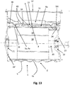
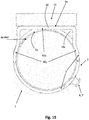
Figur 13- zeigt im Längsschnitt eine Ausgestaltung mit durchgehend gewelltem Hülsenelement und eingelegten Wärmerohren;
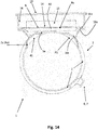
Figur 14- zeigt die
Ausgestaltung aus Figur 13 im Querschnitt; und Figur 15- zeigt eine zu
Figur 13 alternative Ausgestaltung im Querschnitt.
- Figure 1
- shows a temperature control device according to the invention in a perspective view;
- Figure 2
- shows a possible connection design in the area of the supply line or discharge line in the temperature control device according to FIG
Figure 1 ; - Figure 3
- shows a cross section in an embodiment of the sleeve element according to
Figure 1 with a device for influencing the flow; - Figure 4
- shows in cross section an embodiment with a heat pipe or vapor chamber;
- Figure 5
- shows, in cross section, a configuration with an inverter housing made of cast material;
- Figure 6
- shows in cross section an embodiment with several printed circuit boards to be cooled;
- Figure 7
- shows, in a partial cross section, an embodiment with a deep-drawn housing and without a bearing plate divided on the output side;
- Figure 8
- shows in longitudinal section an embodiment with stiffeners or heat-conducting ribs within the sleeve element;
- Figure 9
- shows in longitudinal section an embodiment with a deep-drawn module housing;
- Figure 10
- shows in longitudinal section an embodiment with a separate receiving element for the power electronics and a separate cooling plate;
- Figure 11
- shows in cross section an embodiment with the sleeve element rotated relative to the receiving element;
- Figure 12
- shows in cross section a variant of the embodiment according to FIG. 11;
- Figure 13
- shows in longitudinal section an embodiment with a continuously corrugated sleeve element and inserted heat pipes;
- Figure 14
- shows the design
Figure 13 in cross section; and - Figure 15
- shows one to
Figure 13 alternative configuration in cross section.
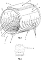
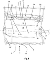
Die Temperiervorrichtung 1 umfasst ein Hülsenelement 2, welches einen Innenraum 3 zum Aufnehmen eines Elektromoduls definiert. Das Hülsenelement 2 besitzt eine umfänglich im Wesentlichen, das heißt bis auf Zu- und Ableitungen, auf die weiter unten noch näher eingegangen wird, geschlossene Mantelfläche 4. Diese Mantelfläche 4 ist in einem ersten Teilbereich gewellt ausgebildet. Einige der Wellen sind in
Im Bereich der Zuleitung 6 und der Ableitung 7 für das Temperierfluid kann die Temperiervorrichtung 1 wie in
Das in
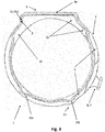
Unter Bezugnahme auf
Zu diesem Zweck ist das Hülsenelement vorzugsweise aus einem gut wärmeleitenden metallischen Material gebildet, insbesondere aus Stahl. Die konkrete Formgebung gemäß
Wie man der
In
Die Lage und Ausgestaltung der beschriebenen Strömungsbeeinflussungselemente ist keinesfalls auf die in
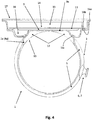
In
Auf dem Bereich der ebenen Fläche 9a in dem ebenen Mantelflächenabschnitt 9 ist ein Wärmeüberträgerelement 13 angeordnet. Bei diesem Wärmeüberträgerelement 13 kann es sich insbesondere um ein Wärmerohr oder eine Vaporchamber handeln, ohne dass die Erfindung auf eine diese besonderen Ausgestaltungen beschränkt wäre. Alternativ kommt auch die Verwendung einer Wärmeleitpaste als Wärmeüberträger in Betracht. Das Wärmeüberträgerelement 13 schafft eine wärmeleitende Verbindung zwischen dem Hülsenelement 2 und einer Leiterplatte 14, auf welcher Leiterplatte 14 die zu kühlende (Leistungs-)Elektronik 15 angeordnet ist, die in
In
Das Wärmeüberträgerelement 13 ist bei der Ausgestaltung gemäß
In
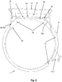
Die elektrische Kontaktierung von Stator 19 und Elektronik (Inverter) 15 wird über einen Durchbruch 24 in dem Hülsenelement 2 sowie in dem Modulgehäuse (Statorgehäuse) 10 realisiert. Gemäß der Darstellung in
Der Lagerschild 23 ist vorteilhafterweise ungeteilt (Alternativen siehe weiter unten), wodurch eine entsprechende Bauteilreduktion erreichbar ist.The
Für eine verbesserte Montierbarkeit kann zusätzlich zwischen dem Stator 19 und dem Durchbruch 24 für die elektrische Kontaktierung eine Durchmesserveränderung, vorzugsweise eine positive Durchmesserveränderung, vorgesehen sein (nicht dargestellt). Dadurch lässt sich erreichen, dass derjenige Bereich des Statorsitzes innerhalb des Modulgehäuses 10, der eng toleriert sein muss, axial verkleinert werden kann, was mit einer entsprechenden Kostenersparnis einhergeht.For improved mountability, a change in diameter, preferably a positive change in diameter, can additionally be provided between the
Gut erkennbar ist in
In
Besonders bevorzugt ist die gemeinsame Einbindung von Modulgehäuse 10 und Hülsenelement 2 stirnseitig im Bereich der Lagerschilde 23 (abtriebsseitig) und 23'.Particularly preferred is the common integration of the
Bei der Ausgestaltung gemäß
Zwischen dem Modulgehäuse 10 und dem Hülsenelement 2 im Bereich des Strömungsraums 3 sind verschieden ausgeformte Versteifungs- bzw. Wärmeleitrippen dargestellt, um für einen verbesserten Wärmeübergang und für eine mechanische Stabilisierung zu sorgen. Selbstverständlich müssen nicht alle gezeigten Geometrien der Versteifungs-/Wärmeleitrippen 25 bei ein- und derselben Ausführungsform realisiert sein.Between the
Die bereits erwähnte
Alle bisher vorgestellten Ausführungsformen unterfallen nicht dem vorgeschlagenen Patentanspruch 1. Die dort gezeigten Merkmale können jedoch zusätzlich bei den nachfolgend beschriebenen Ausführungsformen zum Einsatz kommen.None of the embodiments presented so far are not subject to the proposed
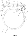
Wie man
Hülsenelement 2 und Kühlplatte 29 sind im Bereich der Zuleitung 6 bzw. Ableitung 29c konisch komplementär ausgebildet, wie in
Wie man der
Bezugszeichen 29d zeigt eine Zuleitung für das Temperierfluid zu der Kühlplatte 29 bzw. in den dortigen Strömungsraum 29b.
Die U-Form der Wärmerohre 40 gemäß
Claims (19)
Applications Claiming Priority (1)
| Application Number | Priority Date | Filing Date | Title |
|---|---|---|---|
| DE102019109751.7A DE102019109751A1 (en) | 2019-04-12 | 2019-04-12 | Temperature control device for an electric module and an electric module with one |
Publications (1)
| Publication Number | Publication Date |
|---|---|
| EP3723246A1 true EP3723246A1 (en) | 2020-10-14 |
Family
ID=70154409
Family Applications (1)
| Application Number | Title | Priority Date | Filing Date |
|---|---|---|---|
| EP20167285.4A Withdrawn EP3723246A1 (en) | 2019-04-12 | 2020-03-31 | Temperature regulating device for an electric module and electric module with such a device |
Country Status (3)
| Country | Link |
|---|---|
| EP (1) | EP3723246A1 (en) |
| DE (1) | DE102019109751A1 (en) |
| WO (1) | WO2020207867A1 (en) |
Cited By (2)
| Publication number | Priority date | Publication date | Assignee | Title |
|---|---|---|---|---|
| DE102021106887A1 (en) | 2021-03-19 | 2022-09-22 | Witzenmann Gmbh | Temperature control device in an electrical machine |
| WO2022194784A1 (en) * | 2021-03-19 | 2022-09-22 | Witzenmann Gmbh | Cooling system, electric drive unit, electric vehicle, and method for cooling an electric drive unit |
Families Citing this family (4)
| Publication number | Priority date | Publication date | Assignee | Title |
|---|---|---|---|---|
| DE102020120947A1 (en) | 2020-08-07 | 2022-02-10 | Witzenmann Gmbh | Temperature control device for an electric module, electric module with temperature control device and method for temperature control of an electric module |
| DE102021100899A1 (en) | 2021-01-18 | 2022-07-21 | Witzenmann Gmbh | Housing arrangement, temperature-controlled electronic module with such and method for temperature-controlling an electronic module |
| DE102021103138A1 (en) * | 2021-02-10 | 2022-08-11 | Witzenmann Gmbh | Temperature control device for an electrical module, electrical module and method for temperature control of such |
| DE102021208239A1 (en) | 2021-07-29 | 2023-02-02 | Volkswagen Aktiengesellschaft | Electrical interface with thermal decoupling |
Citations (4)
| Publication number | Priority date | Publication date | Assignee | Title |
|---|---|---|---|---|
| EP2592724A2 (en) * | 2011-11-10 | 2013-05-15 | Kabushiki Kaisha Yaskawa Denki | Rotating electrical machine |
| CN207835225U (en) * | 2018-01-29 | 2018-09-07 | 台州市台机电机厂 | A kind of water-cooling motor cabinet |
| US20180288907A1 (en) * | 2014-10-31 | 2018-10-04 | Algozen Corporation | A mounting apparatus, for mounting at least one heat dissipating electrical device, optionally including a heat sink body for solid, gas and fluid heat exchange, and circuit board assembly providing interface between circuits |
| DE102018109420A1 (en) | 2017-07-31 | 2019-01-31 | Witzenmann Gmbh | Temperature control device and method for controlling the temperature of an electric module |
Family Cites Families (3)
| Publication number | Priority date | Publication date | Assignee | Title |
|---|---|---|---|---|
| KR101256078B1 (en) * | 2010-06-10 | 2013-04-18 | 로베르트 보쉬 게엠베하 | Charging appratus |
| DE102011076140A1 (en) * | 2011-05-19 | 2012-11-22 | Schaeffler Technologies AG & Co. KG | Cooling jacket for electric motor |
| DE102015101955A1 (en) * | 2015-02-11 | 2016-08-11 | Witzenmann Gmbh | Device and method for tempering a body |
-
2019
- 2019-04-12 DE DE102019109751.7A patent/DE102019109751A1/en active Pending
-
2020
- 2020-03-31 EP EP20167285.4A patent/EP3723246A1/en not_active Withdrawn
- 2020-03-31 WO PCT/EP2020/059153 patent/WO2020207867A1/en active Application Filing
Patent Citations (4)
| Publication number | Priority date | Publication date | Assignee | Title |
|---|---|---|---|---|
| EP2592724A2 (en) * | 2011-11-10 | 2013-05-15 | Kabushiki Kaisha Yaskawa Denki | Rotating electrical machine |
| US20180288907A1 (en) * | 2014-10-31 | 2018-10-04 | Algozen Corporation | A mounting apparatus, for mounting at least one heat dissipating electrical device, optionally including a heat sink body for solid, gas and fluid heat exchange, and circuit board assembly providing interface between circuits |
| DE102018109420A1 (en) | 2017-07-31 | 2019-01-31 | Witzenmann Gmbh | Temperature control device and method for controlling the temperature of an electric module |
| CN207835225U (en) * | 2018-01-29 | 2018-09-07 | 台州市台机电机厂 | A kind of water-cooling motor cabinet |
Cited By (3)
| Publication number | Priority date | Publication date | Assignee | Title |
|---|---|---|---|---|
| DE102021106887A1 (en) | 2021-03-19 | 2022-09-22 | Witzenmann Gmbh | Temperature control device in an electrical machine |
| WO2022194785A1 (en) * | 2021-03-19 | 2022-09-22 | Witzenmann Gmbh | Temperature-control device for an electric machine |
| WO2022194784A1 (en) * | 2021-03-19 | 2022-09-22 | Witzenmann Gmbh | Cooling system, electric drive unit, electric vehicle, and method for cooling an electric drive unit |
Also Published As
| Publication number | Publication date |
|---|---|
| DE102019109751A1 (en) | 2020-10-15 |
| WO2020207867A1 (en) | 2020-10-15 |
Similar Documents
| Publication | Publication Date | Title |
|---|---|---|
| EP3723246A1 (en) | Temperature regulating device for an electric module and electric module with such a device | |
| DE102018109420A1 (en) | Temperature control device and method for controlling the temperature of an electric module | |
| EP2302183B1 (en) | Exhaust gas or charged air heat exchanger | |
| DE102008001660A1 (en) | Lightweight flow heat exchanger | |
| DE102019109313B4 (en) | Electric drive with heat exchanger section | |
| DE112010002744T5 (en) | Heat exchanger with cast housing and method of making the same | |
| DE102008002430A1 (en) | Exhaust gas heat exchanger with vibration-damped exchanger tube bundle | |
| DE102008001659B4 (en) | Exhaust gas heat exchanger with integrated mounting interface | |
| EP3056847B1 (en) | Method and device for tempering a body | |
| DE102019133363A1 (en) | Cooling system, electric drive unit, electric vehicle and method for cooling an electric drive unit | |
| DE102018122414A1 (en) | Temperature control device and method for temperature control of an electrical module | |
| WO2013007399A1 (en) | Transmission device comprising at least one electric motor for a vehicle | |
| DE4212243C2 (en) | transmission | |
| WO2018215237A1 (en) | Heat transfer element, temperature-control device, and battery housing having at least one heat transfer element | |
| DE102011079157B4 (en) | Transmission device with at least one electric motor with radially limited space for a vehicle | |
| WO2021099034A1 (en) | Modular electric axle drive | |
| DE102019117155A1 (en) | Electric drive for a vehicle and vehicle with the electric drive | |
| DE102009000263A1 (en) | Waste-gas heat exchanger for exhaust gas train in exhaust gas reconducting system of internal combustion engine of motor vehicle, has overflow opening provided in plate that provides flow path extending between inlet and outlet regions | |
| EP1862651B1 (en) | Insulating device for a machine part, in particular one with a hot medium throughflow | |
| DE102020212685A1 (en) | Device for supplying oil to an electric machine and electric machine comprising a device for supplying oil | |
| EP3926215A1 (en) | Device for improving the cooling of a transmission housing | |
| WO2021047831A1 (en) | System housing for an electrical axle drive of a motor vehicle and electrical axle drive for a motor vehicle | |
| DE102016201691A1 (en) | Liquid-cooled electric machine for a motor vehicle | |
| EP3594042A1 (en) | Axle generator unit for a vehicle | |
| DE102020106849A1 (en) | Liquid pump, in particular for supplying a transmission of an electric or hybrid drive module of a motor vehicle |
Legal Events
| Date | Code | Title | Description |
|---|---|---|---|
| PUAI | Public reference made under article 153(3) epc to a published international application that has entered the european phase |
Free format text: ORIGINAL CODE: 0009012 |
|
| STAA | Information on the status of an ep patent application or granted ep patent |
Free format text: STATUS: THE APPLICATION HAS BEEN PUBLISHED |
|
| AK | Designated contracting states |
Kind code of ref document: A1 Designated state(s): AL AT BE BG CH CY CZ DE DK EE ES FI FR GB GR HR HU IE IS IT LI LT LU LV MC MK MT NL NO PL PT RO RS SE SI SK SM TR |
|
| AX | Request for extension of the european patent |
Extension state: BA ME |
|
| STAA | Information on the status of an ep patent application or granted ep patent |
Free format text: STATUS: REQUEST FOR EXAMINATION WAS MADE |
|
| 17P | Request for examination filed |
Effective date: 20210114 |
|
| RBV | Designated contracting states (corrected) |
Designated state(s): AL AT BE BG CH CY CZ DE DK EE ES FI FR GB GR HR HU IE IS IT LI LT LU LV MC MK MT NL NO PL PT RO RS SE SI SK SM TR |
|
| STAA | Information on the status of an ep patent application or granted ep patent |
Free format text: STATUS: EXAMINATION IS IN PROGRESS |
|
| 17Q | First examination report despatched |
Effective date: 20210813 |
|
| STAA | Information on the status of an ep patent application or granted ep patent |
Free format text: STATUS: THE APPLICATION IS DEEMED TO BE WITHDRAWN |
|
| 18D | Application deemed to be withdrawn |
Effective date: 20231003 |