EP3723071A1 - Apparatus for automatically folding flexible display screen - Google Patents
Apparatus for automatically folding flexible display screen Download PDFInfo
- Publication number
- EP3723071A1 EP3723071A1 EP19861816.7A EP19861816A EP3723071A1 EP 3723071 A1 EP3723071 A1 EP 3723071A1 EP 19861816 A EP19861816 A EP 19861816A EP 3723071 A1 EP3723071 A1 EP 3723071A1
- Authority
- EP
- European Patent Office
- Prior art keywords
- screen
- supporting component
- flexible display
- display screen
- disposed
- Prior art date
- Legal status (The legal status is an assumption and is not a legal conclusion. Google has not performed a legal analysis and makes no representation as to the accuracy of the status listed.)
- Granted
Links
Images


Classifications
-
- F—MECHANICAL ENGINEERING; LIGHTING; HEATING; WEAPONS; BLASTING
- F16—ENGINEERING ELEMENTS AND UNITS; GENERAL MEASURES FOR PRODUCING AND MAINTAINING EFFECTIVE FUNCTIONING OF MACHINES OR INSTALLATIONS; THERMAL INSULATION IN GENERAL
- F16M—FRAMES, CASINGS OR BEDS OF ENGINES, MACHINES OR APPARATUS, NOT SPECIFIC TO ENGINES, MACHINES OR APPARATUS PROVIDED FOR ELSEWHERE; STANDS; SUPPORTS
- F16M11/00—Stands or trestles as supports for apparatus or articles placed thereon ; Stands for scientific apparatus such as gravitational force meters
- F16M11/02—Heads
- F16M11/04—Means for attachment of apparatus; Means allowing adjustment of the apparatus relatively to the stand
- F16M11/06—Means for attachment of apparatus; Means allowing adjustment of the apparatus relatively to the stand allowing pivoting
-
- F—MECHANICAL ENGINEERING; LIGHTING; HEATING; WEAPONS; BLASTING
- F16—ENGINEERING ELEMENTS AND UNITS; GENERAL MEASURES FOR PRODUCING AND MAINTAINING EFFECTIVE FUNCTIONING OF MACHINES OR INSTALLATIONS; THERMAL INSULATION IN GENERAL
- F16M—FRAMES, CASINGS OR BEDS OF ENGINES, MACHINES OR APPARATUS, NOT SPECIFIC TO ENGINES, MACHINES OR APPARATUS PROVIDED FOR ELSEWHERE; STANDS; SUPPORTS
- F16M11/00—Stands or trestles as supports for apparatus or articles placed thereon ; Stands for scientific apparatus such as gravitational force meters
- F16M11/02—Heads
- F16M11/18—Heads with mechanism for moving the apparatus relatively to the stand
-
- F—MECHANICAL ENGINEERING; LIGHTING; HEATING; WEAPONS; BLASTING
- F16—ENGINEERING ELEMENTS AND UNITS; GENERAL MEASURES FOR PRODUCING AND MAINTAINING EFFECTIVE FUNCTIONING OF MACHINES OR INSTALLATIONS; THERMAL INSULATION IN GENERAL
- F16M—FRAMES, CASINGS OR BEDS OF ENGINES, MACHINES OR APPARATUS, NOT SPECIFIC TO ENGINES, MACHINES OR APPARATUS PROVIDED FOR ELSEWHERE; STANDS; SUPPORTS
- F16M11/00—Stands or trestles as supports for apparatus or articles placed thereon ; Stands for scientific apparatus such as gravitational force meters
- F16M11/02—Heads
- F16M11/04—Means for attachment of apparatus; Means allowing adjustment of the apparatus relatively to the stand
- F16M11/041—Allowing quick release of the apparatus
-
- F—MECHANICAL ENGINEERING; LIGHTING; HEATING; WEAPONS; BLASTING
- F16—ENGINEERING ELEMENTS AND UNITS; GENERAL MEASURES FOR PRODUCING AND MAINTAINING EFFECTIVE FUNCTIONING OF MACHINES OR INSTALLATIONS; THERMAL INSULATION IN GENERAL
- F16M—FRAMES, CASINGS OR BEDS OF ENGINES, MACHINES OR APPARATUS, NOT SPECIFIC TO ENGINES, MACHINES OR APPARATUS PROVIDED FOR ELSEWHERE; STANDS; SUPPORTS
- F16M11/00—Stands or trestles as supports for apparatus or articles placed thereon ; Stands for scientific apparatus such as gravitational force meters
- F16M11/02—Heads
- F16M11/04—Means for attachment of apparatus; Means allowing adjustment of the apparatus relatively to the stand
- F16M11/06—Means for attachment of apparatus; Means allowing adjustment of the apparatus relatively to the stand allowing pivoting
- F16M11/10—Means for attachment of apparatus; Means allowing adjustment of the apparatus relatively to the stand allowing pivoting around a horizontal axis
-
- F—MECHANICAL ENGINEERING; LIGHTING; HEATING; WEAPONS; BLASTING
- F16—ENGINEERING ELEMENTS AND UNITS; GENERAL MEASURES FOR PRODUCING AND MAINTAINING EFFECTIVE FUNCTIONING OF MACHINES OR INSTALLATIONS; THERMAL INSULATION IN GENERAL
- F16M—FRAMES, CASINGS OR BEDS OF ENGINES, MACHINES OR APPARATUS, NOT SPECIFIC TO ENGINES, MACHINES OR APPARATUS PROVIDED FOR ELSEWHERE; STANDS; SUPPORTS
- F16M13/00—Other supports for positioning apparatus or articles; Means for steadying hand-held apparatus or articles
-
- G—PHYSICS
- G09—EDUCATION; CRYPTOGRAPHY; DISPLAY; ADVERTISING; SEALS
- G09F—DISPLAYING; ADVERTISING; SIGNS; LABELS OR NAME-PLATES; SEALS
- G09F9/00—Indicating arrangements for variable information in which the information is built-up on a support by selection or combination of individual elements
- G09F9/30—Indicating arrangements for variable information in which the information is built-up on a support by selection or combination of individual elements in which the desired character or characters are formed by combining individual elements
-
- G—PHYSICS
- G09—EDUCATION; CRYPTOGRAPHY; DISPLAY; ADVERTISING; SEALS
- G09F—DISPLAYING; ADVERTISING; SIGNS; LABELS OR NAME-PLATES; SEALS
- G09F9/00—Indicating arrangements for variable information in which the information is built-up on a support by selection or combination of individual elements
- G09F9/30—Indicating arrangements for variable information in which the information is built-up on a support by selection or combination of individual elements in which the desired character or characters are formed by combining individual elements
- G09F9/301—Indicating arrangements for variable information in which the information is built-up on a support by selection or combination of individual elements in which the desired character or characters are formed by combining individual elements flexible foldable or roll-able electronic displays, e.g. thin LCD, OLED
-
- H—ELECTRICITY
- H05—ELECTRIC TECHNIQUES NOT OTHERWISE PROVIDED FOR
- H05K—PRINTED CIRCUITS; CASINGS OR CONSTRUCTIONAL DETAILS OF ELECTRIC APPARATUS; MANUFACTURE OF ASSEMBLAGES OF ELECTRICAL COMPONENTS
- H05K5/00—Casings, cabinets or drawers for electric apparatus
- H05K5/02—Details
- H05K5/0247—Electrical details of casings, e.g. terminals, passages for cables or wiring
-
- H—ELECTRICITY
- H05—ELECTRIC TECHNIQUES NOT OTHERWISE PROVIDED FOR
- H05K—PRINTED CIRCUITS; CASINGS OR CONSTRUCTIONAL DETAILS OF ELECTRIC APPARATUS; MANUFACTURE OF ASSEMBLAGES OF ELECTRICAL COMPONENTS
- H05K5/00—Casings, cabinets or drawers for electric apparatus
- H05K5/02—Details
- H05K5/03—Covers
-
- H—ELECTRICITY
- H04—ELECTRIC COMMUNICATION TECHNIQUE
- H04M—TELEPHONIC COMMUNICATION
- H04M1/00—Substation equipment, e.g. for use by subscribers
- H04M1/02—Constructional features of telephone sets
- H04M1/04—Supports for telephone transmitters or receivers
Definitions
- the present application relates to the field of automation device technologies, more particularly to a device for automatically folding a flexible display screen.
- OLED Organic Light-Emitting Diode
- the present application provides a device for automatically folding a flexible display screen, which solves a problem that a phenomenon of "dead folding” or stretching is easily formed in a folding region of the flexible display screen and causes the display screen to fail to display normally.
- a device for automatically folding a flexible display screen including: a screen movable supporting component, configured to support a portion of the flexible display screen; and a bending driving device, configured to drive the screen movable supporting component to perform a variable radius rotation around a fixed rotating shaft to perform a bending action of the flexible display screen.
- a bending angle of the flexible display screen is, the smaller a rotation radius of the screen movable supporting component is.
- the bending driving device includes: a cam having an arcuate surface with a variable radius of curvature; and a driving mechanism, configured to drive the screen movable supporting component to rotate along the arcuate surface of the cam.
- the driving mechanism includes: a motor; and a driving component disposed between the motor and the cam.
- the motor rotates to drive the driving component to drive the screen movable supporting component to rotate along the arcuate surface.
- the driving component includes: a fixing seat, disposed on a motor head of the motor, an end of which located at the fixing seat being connected to the cam; a rotating linkage, disposed on the fixing seat; a slider, connected to an end of the rotating linkage away from the fixing seat; a spring, disposed between the cam and the slider; a slider platen, disposed on an end of the spring away from the slider, the slider platen and the rotating linkage being locked by a screw; and a bearing, disposed on the rotating linkage, and locked with the rotating linkage by a screw.
- the device for automatically folding a flexible display screen further includes a base.
- the base includes a through hole, and the driving mechanism is disposed in the through hole.
- a shape of the base is one or more of the following shapes: orthogon, rectangle, circle, and the like.
- a shape of the through hole is one or more of the following shapes: circle and square.
- a material of the base is one or more of the following materials: metal and plastic.
- the device for automatically folding a flexible display screen further includes a driving circuit board, disposed on the base, fixed to the base by a screw, and configured to drive the motor to rotate; and a cable, disposed on the base. One end of the cable is electrically connected to the driving circuit board, and the other end of the cable is electrically connected to the motor.
- the driving circuit board is disposed inside the through hole, or the driving circuit board is disposed at a side of the base adjacent to the motor, or the driving circuit board is disposed at a side of the base adjacent to the supporting component.
- the device for automatically folding a flexible display screen further includes an upper cover, covering a surface of an end of the through hole adjacent to the screen movable supporting component. The cam is disposed inside the upper cover.
- a shape of the upper cover is one or more of the following shapes: orthogon, circle and rectangle.
- a material of the upper cover is one or more of the following materials: metal and plastic.
- the device for automatically folding a flexible display screen further includes a bottom cover, covering a surface of an end of the through hole near away from the upper cover.
- a shape of the bottom cover is one or more of the following shapes: orthogon, rectangle and circle.
- a material of the bottom cover is one or more of the following materials: metal and plastic.
- the device for automatically folding a flexible display screen further includes a screen fixed supporting component, fixed on an end of the upper cover away from the base, and arranged side by side with the screen movable supporting component on both sides of a folding region of the flexible display screen.
- the device for automatically folding a flexible display screen further includes a soft rubber rotating shaft, disposed between the screen movable supporting component and the screen fixed supporting component, configured to connect the screen movable supporting component with the screen fixed supporting component.
- the device for automatically folding a flexible display screen further includes a screen fixing plate, disposed on the screen fixed supporting component, and configured to fix the flexible display screen.
- a material of the fixing plate is one or more of the following materials: metal and wood.
- the device for automatically folding a flexible display screen further includes at least one screen batten, fixed on the screen movable supporting component and the screen fixing plate by a screw, and configured to fix the flexible display screen.
- the motor is a servo motor.
- the embodiments of the present application provide a device for automatically folding a flexible display screen.
- the device for automatically folding a flexible display screen includes a screen movable supporting component and a bending driving device.
- the screen supporting component is configured to support a portion of the flexible display screen
- the bending driving device is configured to drive the screen movable supporting component to perform a variable radius rotation around a fixed rotating shaft to perform a bending action of the flexible display screen.
- the larger a bending angle of the flexible display screen is, the smaller a rotation radius of the screen movable supporting component is.
- the rotation radius is decreased, and when the flexible display screen is changed from the folded state to the flattened state, the rotation radius is increased, which changes the stress on the flexible display screen during a stretching process, and avoids a problem that the flexible display screen may not be displayed normally due to screen failure caused by stretching during a bending process.
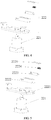
- FIG. 1 is a schematic structural diagram illustrating a device for automatically folding a flexible display screen according to an embodiment of the present application.
- FIG. 2 is a schematic structural diagram illustrating a device for automatically folding a flexible display screen according to an embodiment of the present application.
- the device for automatically folding a flexible display screen includes a screen movable supporting component 1 and a bending driving device 2.
- the screen movable supporting component 1 is configured to support a portion of the flexible display screen 9, and the bending driving device 2 is configured to drive the screen movable supporting component 1 to perform a variable radius rotation around a fixed rotating shaft, thereby performing a bending action of the flexible display device.
- the fixed rotating shaft is disposed in a direction of a bending region of the flexible display screen 9.
- the fixed rotating shaft may be a solid rotating shaft, the solid rotating shaft is disposed in the direction of the bending region of the flexible display screen 9, and the bending driving device 2 drives the screen movable supporting component 1 to perform a variable radius motion around the solid rotating shaft.
- the fixed rotating shaft may also be a virtual rotating shaft, that is, there is no solid rotating shaft.
- the bending driving device 2 drives the screen movable supporting component 1 to perform the variable radius motion only around the direction of the bending region of the flexible display screen 9.
- the fixed rotating shaft may be a virtual rotating shaft or a solid rotating shaft, which is not limited in the present application. The larger a bending angle of the flexible display screen 9 is, the smaller a rotation radius of the screen movable supporting component 1 is.
- the rotation radius is decreased; and when the flexible display screen 9 is changed from the folded state to the flattened state, the rotation radius is increased.
- the stress on the flexible display screen 9 during a stretching process is changed, and a problem that the flexible display screen 9 may not be displayed normally due to screen failure caused by stretching during a bending process is avoided.
- the bending of the flexible display screen 9 may be a bending toward a side facing the display screen, or may be a bending toward a side away from the display screen, and the bending direction of the flexible display screen 9 is not limited by the present application.
- FIG. 3 is a schematic structural diagram illustrating a bending driving device 2 according to an embodiment of the present application.
- the bending driving device 2 includes a cam 21 having an arcuate surface with a variable radius of curvature and a driving mechanism 22.
- the cam 21 is used to change a moving radius of the screen movable supporting component 1 so that the screen movable supporting component 1 rotates along the arcuate surface of the cam 21.
- the driving mechanism 22 is configured to drive the screen movable supporting component 1 to rotate along the arcuate surface of the cam 21.
- the driving mechanism 22 drives the screen movable supporting component 1 to perform a variable curvature radius rotation along the arcuate surface of the cam 21.
- the rotation radius is decreased, and when the flexible display screen 9 is changed from the folded state to the flattened state, the rotation radius is increased.
- the stress on the flexible display screen 9 during a stretching process is changed, and a problem that the flexible display screen 9 may not be displayed normally due to screen failure caused by stretching during a bending process is avoided.
- a curvature of the arcuate surface of the cam 21 with the variable curvature radius may be designed according to a specific folding manner of the flexible display screen 9, and the present application is not limited to a specific curvature of the variable curvature radius of the cam 21.
- FIG. 4 is a schematic structural diagram illustrating a driving mechanism 22 according to an embodiment of the present application.
- the driving mechanism 22 includes a motor 221 and a driving component 222.
- the driving component 222 is disposed between the motor 221 and the cam 21, and the motor 221 rotates to drive the driving component 222 to move.
- the driving component 222 drives the screen movable supporting component 1 to rotate along the arcuate surface of the cam 21 during moving, thereby realizing a change of the moving radius of the screen movable supporting component 1, thus the stress on the flexible display screen 9 during a folding process is reduced, and a problem that the flexible display screen 9 may not be displayed normally due to screen failure caused by stretching during a bending process is avoided.
- the motor 221 may be a servo motor, a stepping motor, a common motor, or the like.
- the present application is not limited to a specific type of the motor 221 under the premise that the motor 221 may drive the screen supporting component to perform a variable radius rotation along the shape of the cam 21.
- FIG. 5 is a schematic structural diagram illustrating a driving component according to an embodiment of the present application.
- the driving component 222 includes a fixing seat 2221, a rotating linkage 2222, a slider platen 2225, a slider 2223, a spring 2224, and a bearing.
- the fixing seat 2221 is connected to a head of the motor 221; the rotating linkage 2222 is disposed on an end of the fixing seat 2221 away from the motor 221; the slider 2223 is connected to an end of the rotating linkage 2222 away from the fixing seat 2221; the spring 2224 is disposed between the slider 2223 and the cam 21; and the sliding platen and the rotating linkage 2222 are locked by a screw, the bearing is mounted on the rotating linkage 2222, and the bearing and the rotating linkage 2222 may be locked by a screw.
- the slider 2223 drives the screen movable supporting component 1 to perform a variable radius rotation along the shape of the cam 21 under the elastic force of the spring 2224, so that phenomena such as folding fatigue and folding failure caused by stretching may be avoided when the screen is bent.
- a screw fixing manner mentioned in this embodiment may also be a rivet fixing manner, and the present application is not limit to a specific fixing workpiece.
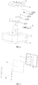
- FIG. 6 is a schematic structural diagram illustrating an upper cover 4, a base 3, and a bottom cover 5 according to an embodiment of the present application.
- the device for automatically folding a flexible display screen further includes a base 3, and the base 3 includes a through hole.
- a driving mechanism 22 is disposed in the through hole, and the base 3 may surround a supporting component supporting the motor 221 and the motor 221, thereby protecting and beautifying the supporting component and the motor 221.
- the through hole of the base 3 may be a circular through hole, a square through hole, an irregularly shaped through hole, or the like.
- the present application is not limited to the specific shape of the through hole of the base 3.
- the shape of the base 3 may be an orthogon, a rectangle, a circle, an orthogon with four rounded corners, a rectangle with four rounded corners, or the like, and the present application is not limited to an outer shape of the base 3.
- a material of the base 3 may be metal, plastic, or the like, and the present application is not limited to the specific material of the base 3.
- the device for automatically folding a flexible display screen includes a driving circuit board 6 and a cable.
- the driving circuit board 6 is disposed on the base 3 and fixed to the base 3 by a screw.
- the cable is disposed on the base 3 and electrically connected to the driving circuit board 6.
- One end of the cable is electrically connected to the driving circuit board 6, and the other end is electrically connected to the motor 221.
- the driving circuit board 6 and the cable are configured to drive and control the rotation of the motor 221, and the rotation of the motor 221 drives the rotation of the screen supporting component, thereby realizing that the flexible display screen 9 gets rid of manual work and realizes the function of automatic bending.
- the driving circuit board 6 may be disposed inside the through hole of the base 3, and may also be disposed on a side of the base 3 adjacent to a fixing component of the motor 221, or may also be disposed on a side of the base 3 adjacent to the screen supporting component.
- the present application is not limited to the specific position where the driving circuit board 6 is located in the motor 221.
- the device for automatically folding the flexible display screen further includes an upper cover 4 covering the base 3, and is disposed on an end of the base 3 adjacent to the screen supporting component.
- the cam 21 is disposed inside the upper cover 4.
- the upper cover 4 may protect the supporting component of the motor 221 and the motor 221, and beautify the device for automatically folding the flexible display screen.
- the shape of the upper cover 4 may be an orthogon, a rectangle, a circle, or the like, and the present application is not limited to the outer shape of the upper cover 4.
- the material of the upper cover 4 may be metal, plastic or the like, and the present application is not limited to the specific material of the upper cover 4.
- the device for automatically folding the flexible display screen further includes a bottom cover 5 covering the base 3, and is disposed under a bottom of the base 3 away from the upper cover 4.
- the bottom cover 5 may play a role in protecting and supporting the motor 221, and may prevent components such as the motor 221 from falling out due to the weak connection, which affects the exhibition effect.
- the shape of the bottom cover 5 may be an orthogon, a rectangle, a circle, or the like, and the present application is not limited to the outer shape of the bottom cover 5.
- the material of the bottom cover 5 may be metal, plastic, or the like, and the present application is not limited to the specific material of the bottom cover 5.
- FIG. 7 is a schematic structural diagram illustrating a screen fixed supporting component according to an embodiment of the present application.
- the screen supporting component includes a screen movable supporting component 1 and a screen fixed supporting component 7.
- the screen movable supporting component 1 and the screen fixed supporting component 7 are arranged side by side on both sides of a folding region of the flexible display screen 9.
- the screen movable supporting component 1 is configured to support one side of the folding region of the flexible display screen 9, and the screen fixed supporting component 7 is configured to support the other side of the folding region of the flexible display screen 9.
- a side of the screen movable supporting component 1 adjacent to the cam 21 is connected to the cam 21.
- the motor 221 drives the screen movable supporting component 1 to perform a variable radius motion along the outer shape of the cam 21, and the screen fixed supporting component 7 is fixed, thereby realizing that when the motor 221 rotates, a portion of the flexible display screen 9 fixed on the screen fixed supporting component 7 is fixed, and a portion of the flexible display screen 9 fixed on the screen movable supporting component 1 is driven by the motor 221 to perform a variable radius motion along the cam 21, realizing a function of automatically folding and unfolding of the flexible display screen 9, and saving labor cost.
- the automatic folding device may be configured for exhibitions, improving the exhibition efficiency and effect.
- the screen supporting component further includes a soft rubber rotating shaft, and the soft rubber rotating shaft is disposed between the screen movable supporting component 1 and the screen fixed supporting component 7 for connecting the screen movable supporting component 1 and the screen fixed supporting component 7.
- the screen movable supporting component 1 drives the soft rubber rotating shaft to rotate together when rotating, so that the screen movable supporting component 1 drives a portion of the flexible display screen 9 to rotate, and the screen fixed supporting component 7 fixes the rest of the flexible display screen 9 so as not to rotate.
- the material of the soft rubber rotating shaft may be soft rubber.
- the soft rubber has elasticity, and does not scratch or squeeze the flexible display screen 9 during a rotation process, which protects the flexible display screen 9.
- the device for automatically folding the flexible display screen includes a fixing plate.
- the fixing plate is disposed on a screen fixing component for fixing the flexible display screen 9, which may prevent a fixed portion of the flexible display screen 9 from moving during a folding process and affecting a rotating effect.
- the fixing plate may be made of metal, wood or other materials capable of satisfying a fixing effect, and the present application is not limited to the specific material of the fixing plate.
- the device for automatically folding the flexible display screen includes a plurality of screen battens 8.
- a portion of the flexible display screen 9 is fixed on the screen fixed supporting component 7, and the rest of the flexible display screen 9 is fixed on the screen movable supporting component 1.
- the screen battens 8 are pressed on a surface of the flexible display screen 9, and the screen batten 8 and the screen supporting component are fixed by a screw, so that the flexible display screen 9 is fixed on the device for automatically folding flexible display screen, and the position of the flexible display screen 9 is prevented from shifting during an automatic bending process, thereby improving the bending effect.
- the number of the screen battens 8 may be at least two.
- the screen battens 8 include two screen battens, the screen battens 8 may be frame-shaped structures, and disposed on opposite ends of a bending line of the flexible display screen 9 respectively. After placing the rectangular frame on a surface of the flexible display screen 9, one screen batten 8 is connected to the screen fixed supporting component 7, and the other screen batten 8 is connected to the screen movable supporting component 1.
- the screen battens 8 include a plurality of screen battens 8
- the plurality of screen battens 8 are distributed on both sides of a bending region of the flexible display screen 9 respectively.
- the screen batten 8 may be formed into a strip, and the plurality of screen battens 8 are connected and fixed to the screen fixed supporting component 7 and the screen movable supporting component 1 respectively.
- the present application is not limited to the number and shape of the screen battens 8.
Landscapes
- Engineering & Computer Science (AREA)
- General Engineering & Computer Science (AREA)
- Mechanical Engineering (AREA)
- Microelectronics & Electronic Packaging (AREA)
- Physics & Mathematics (AREA)
- General Physics & Mathematics (AREA)
- Theoretical Computer Science (AREA)
- Devices For Indicating Variable Information By Combining Individual Elements (AREA)
- Signal Processing (AREA)
Abstract
Description
- The present application claims priority to Chinese patent application No.
201821534740.3, filed on September 19, 2018 - The present application relates to the field of automation device technologies, more particularly to a device for automatically folding a flexible display screen.
- Because an Organic Light-Emitting Diode (OLED) emits light by itself, its volume is thin, its energy consumption is small, and it is flexible, such a display technology may be used in military, medical, exhibition and other occasions. Current display industries is making terminal products such as mobile phones develop in terms of flexibility based on its flexible and foldable advantages, and current display leading enterprises are gradually beginning to lay out folding displays. But due to a limitation of folding structures, a flexible folding screen as an emerging display product still exists a phenomenon of "dead folding" or stretching easily formed in a folding region, thereby causing the display screen to fail to display normally.
- In view of this, the present application provides a device for automatically folding a flexible display screen, which solves a problem that a phenomenon of "dead folding" or stretching is easily formed in a folding region of the flexible display screen and causes the display screen to fail to display normally.
- According to an aspect of the present application, a device for automatically folding a flexible display screen is provided, including: a screen movable supporting component, configured to support a portion of the flexible display screen; and a bending driving device, configured to drive the screen movable supporting component to perform a variable radius rotation around a fixed rotating shaft to perform a bending action of the flexible display screen. The larger a bending angle of the flexible display screen is, the smaller a rotation radius of the screen movable supporting component is.
- In an embodiment, the bending driving device includes: a cam having an arcuate surface with a variable radius of curvature; and a driving mechanism, configured to drive the screen movable supporting component to rotate along the arcuate surface of the cam.
- In an embodiment, the driving mechanism includes: a motor; and a driving component disposed between the motor and the cam. The motor rotates to drive the driving component to drive the screen movable supporting component to rotate along the arcuate surface.
- In an embodiment, the driving component includes: a fixing seat, disposed on a motor head of the motor, an end of which located at the fixing seat being connected to the cam; a rotating linkage, disposed on the fixing seat; a slider, connected to an end of the rotating linkage away from the fixing seat; a spring, disposed between the cam and the slider; a slider platen, disposed on an end of the spring away from the slider, the slider platen and the rotating linkage being locked by a screw; and a bearing, disposed on the rotating linkage, and locked with the rotating linkage by a screw.
- In an embodiment, the device for automatically folding a flexible display screen further includes a base. The base includes a through hole, and the driving mechanism is disposed in the through hole.
- In an embodiment, a shape of the base is one or more of the following shapes: orthogon, rectangle, circle, and the like.
- In an embodiment, a shape of the through hole is one or more of the following shapes: circle and square.
- In an embodiment, a material of the base is one or more of the following materials: metal and plastic.
- In an embodiment, the device for automatically folding a flexible display screen further includes a driving circuit board, disposed on the base, fixed to the base by a screw, and configured to drive the motor to rotate; and a cable, disposed on the base. One end of the cable is electrically connected to the driving circuit board, and the other end of the cable is electrically connected to the motor.
- In an embodiment, the driving circuit board is disposed inside the through hole, or the driving circuit board is disposed at a side of the base adjacent to the motor, or the driving circuit board is disposed at a side of the base adjacent to the supporting component. In an embodiment, the device for automatically folding a flexible display screen further includes an upper cover, covering a surface of an end of the through hole adjacent to the screen movable supporting component. The cam is disposed inside the upper cover.
- In an embodiment, a shape of the upper cover is one or more of the following shapes: orthogon, circle and rectangle.
- In an embodiment, a material of the upper cover is one or more of the following materials: metal and plastic.
- In an embodiment, the device for automatically folding a flexible display screen further includes a bottom cover, covering a surface of an end of the through hole near away from the upper cover.
- In an embodiment, a shape of the bottom cover is one or more of the following shapes: orthogon, rectangle and circle.
- In an embodiment, a material of the bottom cover is one or more of the following materials: metal and plastic.
- In an embodiment, the device for automatically folding a flexible display screen further includes a screen fixed supporting component, fixed on an end of the upper cover away from the base, and arranged side by side with the screen movable supporting component on both sides of a folding region of the flexible display screen.
- In an embodiment, the device for automatically folding a flexible display screen further includes a soft rubber rotating shaft, disposed between the screen movable supporting component and the screen fixed supporting component, configured to connect the screen movable supporting component with the screen fixed supporting component.
- In an embodiment, the device for automatically folding a flexible display screen further includes a screen fixing plate, disposed on the screen fixed supporting component, and configured to fix the flexible display screen.
- In an embodiment, a material of the fixing plate is one or more of the following materials: metal and wood.
- In an embodiment, the device for automatically folding a flexible display screen further includes at least one screen batten, fixed on the screen movable supporting component and the screen fixing plate by a screw, and configured to fix the flexible display screen.
- In an embodiment, the motor is a servo motor.
- The embodiments of the present application provide a device for automatically folding a flexible display screen. The device for automatically folding a flexible display screen includes a screen movable supporting component and a bending driving device. The screen supporting component is configured to support a portion of the flexible display screen, and the bending driving device is configured to drive the screen movable supporting component to perform a variable radius rotation around a fixed rotating shaft to perform a bending action of the flexible display screen. The larger a bending angle of the flexible display screen is, the smaller a rotation radius of the screen movable supporting component is. For example, when the flexible display screen is changed from a flattened state to a folded state, the rotation radius is decreased, and when the flexible display screen is changed from the folded state to the flattened state, the rotation radius is increased, which changes the stress on the flexible display screen during a stretching process, and avoids a problem that the flexible display screen may not be displayed normally due to screen failure caused by stretching during a bending process.
-
-
FIG. 1 is a schematic structural diagram illustrating a device for automatically folding a flexible display screen according to an embodiment of the present application. -
FIG. 2 is a schematic structural diagram illustrating a device for automatically folding a flexible display screen according to an embodiment of the present application. -
FIG. 3 is a schematic structural diagram illustrating a bending driving device according to an embodiment of the present application. -
FIG. 4 is a schematic structural diagram illustrating a driving mechanism according to an embodiment of the present application. -
FIG. 5 is a schematic structural diagram illustrating a driving component according to an embodiment of the present application. -
FIG. 6 is a schematic structural diagram illustrating an upper cover, a base, and a bottom cover according to an embodiment of the present application. -
FIG. 7 is a schematic structural diagram illustrating a screen fixed supporting component according to an embodiment of the present application. - A clear and complete description of technical solutions in the embodiments of the present application will be given below, in combination with the accompanying drawings in the embodiments of the present application. Apparently, the embodiments described below are a part, but not all, of the embodiments of the present application. All other embodiments, obtained by those skilled in the art based on the embodiments of the present application without any creative efforts, shall fall within the protection scope of the present application.
-
FIG. 1 is a schematic structural diagram illustrating a device for automatically folding a flexible display screen according to an embodiment of the present application.FIG. 2 is a schematic structural diagram illustrating a device for automatically folding a flexible display screen according to an embodiment of the present application. - As shown in
FIG. 1 andFIG. 2 , the device for automatically folding a flexible display screen includes a screen movable supportingcomponent 1 and abending driving device 2. The screen movable supportingcomponent 1 is configured to support a portion of theflexible display screen 9, and thebending driving device 2 is configured to drive the screen movable supportingcomponent 1 to perform a variable radius rotation around a fixed rotating shaft, thereby performing a bending action of the flexible display device. The fixed rotating shaft is disposed in a direction of a bending region of theflexible display screen 9. The fixed rotating shaft may be a solid rotating shaft, the solid rotating shaft is disposed in the direction of the bending region of theflexible display screen 9, and thebending driving device 2 drives the screen movable supportingcomponent 1 to perform a variable radius motion around the solid rotating shaft. Alternatively, the fixed rotating shaft may also be a virtual rotating shaft, that is, there is no solid rotating shaft. For example, thebending driving device 2 drives the screen movable supportingcomponent 1 to perform the variable radius motion only around the direction of the bending region of theflexible display screen 9. The fixed rotating shaft may be a virtual rotating shaft or a solid rotating shaft, which is not limited in the present application. The larger a bending angle of theflexible display screen 9 is, the smaller a rotation radius of the screen movable supportingcomponent 1 is. For example, when theflexible display screen 9 is changed from a flattened state to a folded state, the rotation radius is decreased; and when theflexible display screen 9 is changed from the folded state to the flattened state, the rotation radius is increased. Thus the stress on theflexible display screen 9 during a stretching process is changed, and a problem that theflexible display screen 9 may not be displayed normally due to screen failure caused by stretching during a bending process is avoided. - It can be understood that the bending of the
flexible display screen 9 may be a bending toward a side facing the display screen, or may be a bending toward a side away from the display screen, and the bending direction of theflexible display screen 9 is not limited by the present application. -
FIG. 3 is a schematic structural diagram illustrating abending driving device 2 according to an embodiment of the present application. - As shown in
FIG. 3 , thebending driving device 2 includes acam 21 having an arcuate surface with a variable radius of curvature and adriving mechanism 22. Thecam 21 is used to change a moving radius of the screen movable supportingcomponent 1 so that the screen movable supportingcomponent 1 rotates along the arcuate surface of thecam 21. Thedriving mechanism 22 is configured to drive the screen movable supportingcomponent 1 to rotate along the arcuate surface of thecam 21. Thedriving mechanism 22 drives the screen movable supportingcomponent 1 to perform a variable curvature radius rotation along the arcuate surface of thecam 21. When theflexible display screen 9 is changed from a flattened state to a folded state, the rotation radius is decreased, and when theflexible display screen 9 is changed from the folded state to the flattened state, the rotation radius is increased. Thus the stress on theflexible display screen 9 during a stretching process is changed, and a problem that theflexible display screen 9 may not be displayed normally due to screen failure caused by stretching during a bending process is avoided. - It can be understood that a curvature of the arcuate surface of the
cam 21 with the variable curvature radius may be designed according to a specific folding manner of theflexible display screen 9, and the present application is not limited to a specific curvature of the variable curvature radius of thecam 21. -
FIG. 4 is a schematic structural diagram illustrating adriving mechanism 22 according to an embodiment of the present application. - As shown in
FIG. 4 , thedriving mechanism 22 includes amotor 221 and adriving component 222. Thedriving component 222 is disposed between themotor 221 and thecam 21, and themotor 221 rotates to drive the drivingcomponent 222 to move. Thedriving component 222 drives the screen movable supportingcomponent 1 to rotate along the arcuate surface of thecam 21 during moving, thereby realizing a change of the moving radius of the screen movable supportingcomponent 1, thus the stress on theflexible display screen 9 during a folding process is reduced, and a problem that theflexible display screen 9 may not be displayed normally due to screen failure caused by stretching during a bending process is avoided. - It can be understood that the
motor 221 may be a servo motor, a stepping motor, a common motor, or the like. The present application is not limited to a specific type of themotor 221 under the premise that themotor 221 may drive the screen supporting component to perform a variable radius rotation along the shape of thecam 21. -
FIG. 5 is a schematic structural diagram illustrating a driving component according to an embodiment of the present application. - As shown in
FIG. 5 , in an embodiment of the present application, thedriving component 222 includes a fixingseat 2221, arotating linkage 2222, aslider platen 2225, aslider 2223, aspring 2224, and a bearing. The fixingseat 2221 is connected to a head of themotor 221; therotating linkage 2222 is disposed on an end of the fixingseat 2221 away from themotor 221; theslider 2223 is connected to an end of therotating linkage 2222 away from the fixingseat 2221; thespring 2224 is disposed between theslider 2223 and thecam 21; and the sliding platen and therotating linkage 2222 are locked by a screw, the bearing is mounted on therotating linkage 2222, and the bearing and therotating linkage 2222 may be locked by a screw. By fixing the screen movable supportingcomponent 1 to theslider 2223 and assembling theslider 2223 on therotating linkage 2222, when themotor 221 drives therotating linkage 2222, theslider 2223 drives the screen movable supportingcomponent 1 to perform a variable radius rotation along the shape of thecam 21 under the elastic force of thespring 2224, so that phenomena such as folding fatigue and folding failure caused by stretching may be avoided when the screen is bent. - It can be understood that a screw fixing manner mentioned in this embodiment may also be a rivet fixing manner, and the present application is not limit to a specific fixing workpiece.
-
FIG. 6 is a schematic structural diagram illustrating anupper cover 4, abase 3, and abottom cover 5 according to an embodiment of the present application. - As shown in
FIG. 6 , the device for automatically folding a flexible display screen further includes abase 3, and thebase 3 includes a through hole. Adriving mechanism 22 is disposed in the through hole, and thebase 3 may surround a supporting component supporting themotor 221 and themotor 221, thereby protecting and beautifying the supporting component and themotor 221. - It can be understood that the through hole of the
base 3 may be a circular through hole, a square through hole, an irregularly shaped through hole, or the like. In a case of easy implementation, convenient operation and installation, the present application is not limited to the specific shape of the through hole of thebase 3. - It can also be understood that the shape of the
base 3 may be an orthogon, a rectangle, a circle, an orthogon with four rounded corners, a rectangle with four rounded corners, or the like, and the present application is not limited to an outer shape of thebase 3. - It can also be understood that a material of the
base 3 may be metal, plastic, or the like, and the present application is not limited to the specific material of thebase 3. - In an embodiment of the present application, the device for automatically folding a flexible display screen includes a driving
circuit board 6 and a cable. The drivingcircuit board 6 is disposed on thebase 3 and fixed to thebase 3 by a screw. The cable is disposed on thebase 3 and electrically connected to the drivingcircuit board 6. One end of the cable is electrically connected to the drivingcircuit board 6, and the other end is electrically connected to themotor 221. The drivingcircuit board 6 and the cable are configured to drive and control the rotation of themotor 221, and the rotation of themotor 221 drives the rotation of the screen supporting component, thereby realizing that theflexible display screen 9 gets rid of manual work and realizes the function of automatic bending. - It can be understood that the driving
circuit board 6 may be disposed inside the through hole of thebase 3, and may also be disposed on a side of thebase 3 adjacent to a fixing component of themotor 221, or may also be disposed on a side of thebase 3 adjacent to the screen supporting component. The present application is not limited to the specific position where the drivingcircuit board 6 is located in themotor 221. - In an embodiment of the present application, the device for automatically folding the flexible display screen further includes an
upper cover 4 covering thebase 3, and is disposed on an end of thebase 3 adjacent to the screen supporting component. Thecam 21 is disposed inside theupper cover 4. Theupper cover 4 may protect the supporting component of themotor 221 and themotor 221, and beautify the device for automatically folding the flexible display screen. - It can be understood that the shape of the
upper cover 4 may be an orthogon, a rectangle, a circle, or the like, and the present application is not limited to the outer shape of theupper cover 4. - It can also be understood that the material of the
upper cover 4 may be metal, plastic or the like, and the present application is not limited to the specific material of theupper cover 4. - In an embodiment of the present application, the device for automatically folding the flexible display screen further includes a
bottom cover 5 covering thebase 3, and is disposed under a bottom of thebase 3 away from theupper cover 4. Thebottom cover 5 may play a role in protecting and supporting themotor 221, and may prevent components such as themotor 221 from falling out due to the weak connection, which affects the exhibition effect. - It can be understood that the shape of the
bottom cover 5 may be an orthogon, a rectangle, a circle, or the like, and the present application is not limited to the outer shape of thebottom cover 5. - It can also be understood that the material of the
bottom cover 5 may be metal, plastic, or the like, and the present application is not limited to the specific material of thebottom cover 5. -
FIG. 7 is a schematic structural diagram illustrating a screen fixed supporting component according to an embodiment of the present application. - As shown in
FIG. 7 , the screen supporting component includes a screen movable supportingcomponent 1 and a screen fixed supportingcomponent 7. The screen movable supportingcomponent 1 and the screen fixed supportingcomponent 7 are arranged side by side on both sides of a folding region of theflexible display screen 9. The screen movable supportingcomponent 1 is configured to support one side of the folding region of theflexible display screen 9, and the screen fixed supportingcomponent 7 is configured to support the other side of the folding region of theflexible display screen 9. A side of the screen movable supportingcomponent 1 adjacent to thecam 21 is connected to thecam 21. When themotor 221 rotates, themotor 221 drives the screen movable supportingcomponent 1 to perform a variable radius motion along the outer shape of thecam 21, and the screen fixed supportingcomponent 7 is fixed, thereby realizing that when themotor 221 rotates, a portion of theflexible display screen 9 fixed on the screen fixed supportingcomponent 7 is fixed, and a portion of theflexible display screen 9 fixed on the screen movable supportingcomponent 1 is driven by themotor 221 to perform a variable radius motion along thecam 21, realizing a function of automatically folding and unfolding of theflexible display screen 9, and saving labor cost. The automatic folding device may be configured for exhibitions, improving the exhibition efficiency and effect. - In an embodiment of the present application, the screen supporting component further includes a soft rubber rotating shaft, and the soft rubber rotating shaft is disposed between the screen movable supporting
component 1 and the screen fixed supportingcomponent 7 for connecting the screen movable supportingcomponent 1 and the screen fixed supportingcomponent 7. The screen movable supportingcomponent 1 drives the soft rubber rotating shaft to rotate together when rotating, so that the screen movable supportingcomponent 1 drives a portion of theflexible display screen 9 to rotate, and the screen fixed supportingcomponent 7 fixes the rest of theflexible display screen 9 so as not to rotate. The material of the soft rubber rotating shaft may be soft rubber. The soft rubber has elasticity, and does not scratch or squeeze theflexible display screen 9 during a rotation process, which protects theflexible display screen 9. - In an embodiment of the present application, the device for automatically folding the flexible display screen includes a fixing plate. The fixing plate is disposed on a screen fixing component for fixing the
flexible display screen 9, which may prevent a fixed portion of theflexible display screen 9 from moving during a folding process and affecting a rotating effect. - It can be understood that the fixing plate may be made of metal, wood or other materials capable of satisfying a fixing effect, and the present application is not limited to the specific material of the fixing plate.
- In an embodiment of the present application, the device for automatically folding the flexible display screen includes a plurality of screen battens 8. A portion of the
flexible display screen 9 is fixed on the screen fixed supportingcomponent 7, and the rest of theflexible display screen 9 is fixed on the screen movable supportingcomponent 1. The screen battens 8 are pressed on a surface of theflexible display screen 9, and the screen batten 8 and the screen supporting component are fixed by a screw, so that theflexible display screen 9 is fixed on the device for automatically folding flexible display screen, and the position of theflexible display screen 9 is prevented from shifting during an automatic bending process, thereby improving the bending effect. - It can be understood that the number of the screen battens 8 may be at least two. When the screen battens 8 include two screen battens, the screen battens 8 may be frame-shaped structures, and disposed on opposite ends of a bending line of the
flexible display screen 9 respectively. After placing the rectangular frame on a surface of theflexible display screen 9, one screen batten 8 is connected to the screen fixed supportingcomponent 7, and the other screen batten 8 is connected to the screen movable supportingcomponent 1. When the screen battens 8 include a plurality ofscreen battens 8, the plurality ofscreen battens 8 are distributed on both sides of a bending region of theflexible display screen 9 respectively. At this time, the screen batten 8 may be formed into a strip, and the plurality ofscreen battens 8 are connected and fixed to the screen fixed supportingcomponent 7 and the screen movable supportingcomponent 1 respectively. In the case of ensuring that theflexible display screen 9 may be firmly fixed on the screen supporting component, and position shifts are not easy to occur during rotating, the present application is not limited to the number and shape of the screen battens 8. - The above are only the preferred embodiments of the present application and are not intended to limit the present application. Any modifications, equivalent substitutions and the like made within the spirit and principle of the present application should be included within the protection scope of the present application.
Claims (20)
- A device for automatically folding a flexible display screen, comprising:a screen movable supporting component supporting a portion of the flexible display screen; anda bending driving device driving the screen movable supporting component to perform a variable radius rotation around a fixed rotating shaft to perform a bending action of the flexible display screen,wherein the larger a bending angle of the flexible display screen is, the smaller a rotation radius of the screen movable supporting component is.
- The device according to claim 1, wherein when the flexible display screen is changed from a flattened state to a folded state, the rotation radius of the screen movable supporting component is decreased, and when the flexible display screen is changed from the folded state to the flattened state, the rotation radius of the screen movable supporting component is increased.
- The device according to claim 1, wherein the bending driving device comprises:a cam having an arcuate surface with a variable radius of curvature; anda driving mechanism, configured to drive the screen movable supporting component to rotate along the arcuate surface of the cam.
- The device according to claim 3, wherein the driving mechanism comprises:a motor; anda driving component disposed between the motor and the cam, wherein the motor rotates to drive the driving component to drive the screen movable supporting component to rotate along the arcuate surface.
- The device according to claim 4, wherein the driving component comprises:a fixing seat, disposed on a motor head of the motor, an end of which located at the fixing seat being connected to the cam;a rotating linkage, disposed on an end of the fixing seat away from the motor;a slider, connected to an end of the rotating linkage away from the fixing seat;a spring, disposed between the cam and the slider;a slider platen, disposed on an end of the spring away from the slider, the slider platen and the rotating linkage being locked by a screw; anda bearing, disposed on the rotating linkage, and locked with the rotating linkage by a screw.
- The device according to claim 3, further comprising a base, wherein the base comprises a through hole, and the driving mechanism is disposed in the through hole.
- The device according to claim 6, wherein a shape of the base is one or more of the following shapes: orthogon, rectangle, circle, and the like;
a material of the base is one or more of the following materials: metal and plastic. - The device according to claim 5, further comprising:a driving circuit board, fixed on the base and driving the motor to rotate; anda cable, disposed on the base, wherein one end of the cable is electrically connected to the driving circuit board, and the other end of the cable is electrically connected to the motor.
- The device according to claim 8, wherein the driving circuit board is disposed inside the through hole, or
the driving circuit board is disposed at a side of the base adjacent to the motor, or
the driving circuit board is disposed at a side of the base adjacent to the supporting component. - The device according to claim 5, further comprising an upper cover, covering a surface of an end of the through hole adjacent to the screen movable supporting component, wherein the cam is disposed inside the upper cover.
- The device according to claim 10, wherein a shape of the upper cover is one or more of the following shapes: orthogon, circle and rectangle;
a material of the upper cover is one or more of the following materials: metal and plastic. - The device according to claim 10, further comprising a bottom cover, covering a surface of an end of the through hole near away from the upper cover.
- The device according to claim 11, wherein a shape of the bottom cover is one or more of the following shapes: orthogon, rectangle and circle;
a material of the bottom cover is one or more of the following materials: metal and plastic. - The device according to claim 1, further comprising a screen fixed supporting component, fixed on an end of the upper cover away from the base, and arranged side by side with the screen movable supporting component on both sides of a folding region of the flexible display screen.
- The device according to claim 13, further comprising a soft rubber rotating shaft, disposed between the screen movable supporting component and the screen fixed supporting component, configured to connect the screen movable supporting component with the screen fixed supporting component.
- The device according to claim 13, further comprising a screen fixing plate, disposed on the screen fixed supporting component to fix the flexible display screen.
- The device according to claim 15, further comprising at least one screen batten, fixed on the screen movable supporting component and the screen fixing plate to fix the flexible display screen.
- The device according to claim 16, wherein the at least one screen batten includes two screen battens, the screen battens are frame-shaped structures, disposed on opposite ends of a bending line of the flexible display screen respectively, one screen batten is connected to the screen fixed supporting component, and the other screen batten is connected to the screen movable supporting component.
- The device according to claim 16, wherein the at least one screen batten includes a plurality of screen battens, distributed on two sides of a bending region of the flexible display screen respectively, the screen batten is formed into a strip, and the plurality of screen battens are connected and fixed to the screen fixed supporting component and the screen movable supporting component respectively.
- The device according to claim 3, wherein the motor is a servo motor.
Applications Claiming Priority (2)
| Application Number | Priority Date | Filing Date | Title |
|---|---|---|---|
| CN201821534740.3U CN208967363U (en) | 2018-09-19 | 2018-09-19 | A kind of device of auto-folder flexible display screen |
| PCT/CN2019/078132 WO2020057067A1 (en) | 2018-09-19 | 2019-03-14 | Apparatus for automatically folding flexible display screen |
Publications (3)
| Publication Number | Publication Date |
|---|---|
| EP3723071A1 true EP3723071A1 (en) | 2020-10-14 |
| EP3723071A4 EP3723071A4 (en) | 2021-05-12 |
| EP3723071B1 EP3723071B1 (en) | 2025-08-13 |
Family
ID=66757848
Family Applications (1)
| Application Number | Title | Priority Date | Filing Date |
|---|---|---|---|
| EP19861816.7A Active EP3723071B1 (en) | 2018-09-19 | 2019-03-14 | Apparatus for automatically folding flexible display screen |
Country Status (6)
| Country | Link |
|---|---|
| US (1) | US11051414B2 (en) |
| EP (1) | EP3723071B1 (en) |
| JP (1) | JP6971405B2 (en) |
| KR (1) | KR102371994B1 (en) |
| CN (1) | CN208967363U (en) |
| WO (1) | WO2020057067A1 (en) |
Families Citing this family (7)
| Publication number | Priority date | Publication date | Assignee | Title |
|---|---|---|---|---|
| CN111930071B (en) * | 2020-08-04 | 2021-10-26 | 歌尔光学科技有限公司 | Control method based on electronic cam, terminal device and storage medium |
| CN112905091A (en) * | 2021-02-09 | 2021-06-04 | 维沃移动通信有限公司 | Application program starting method and device and electronic equipment |
| CN113327514B (en) * | 2021-05-25 | 2022-09-09 | 上海天马微电子有限公司 | Display device and traffic vehicle |
| CN114484195B (en) * | 2021-12-24 | 2023-08-04 | 浙江大丰实业股份有限公司 | Stage rotary LED screen with mechanical arm |
| CN114999331B (en) * | 2022-08-03 | 2022-10-14 | 南京欣网通信科技股份有限公司 | Visual display device based on indoor distributed integrated system |
| CN115599170B (en) * | 2022-10-14 | 2025-09-16 | 淄博松柏电子科技有限公司 | Suspension type screen touch component |
| CN116772065A (en) * | 2023-07-11 | 2023-09-19 | 宁波视睿迪光电有限公司 | A rotating support base and rotating display screen |
Family Cites Families (38)
| Publication number | Priority date | Publication date | Assignee | Title |
|---|---|---|---|---|
| KR200219336Y1 (en) * | 1998-04-02 | 2003-08-19 | 엘지전자 주식회사 | Rotating structure of LCD monitor |
| KR20110075887A (en) * | 2009-12-29 | 2011-07-06 | 엘지전자 주식회사 | Display support |
| KR101292974B1 (en) * | 2010-06-30 | 2013-08-02 | 주식회사 팬택 | Mobile Communication Terminal With Flexible Display |
| US20120154999A1 (en) * | 2010-12-15 | 2012-06-21 | Samsung Electronics Co., Ltd. | Electronic apparatus |
| US8787016B2 (en) * | 2011-07-06 | 2014-07-22 | Apple Inc. | Flexible display devices |
| JP6198194B2 (en) * | 2012-12-05 | 2017-09-27 | 齋藤 敬 | Display device |
| KR101986796B1 (en) * | 2013-01-14 | 2019-06-10 | 삼성디스플레이 주식회사 | Display device |
| KR101875855B1 (en) * | 2014-02-17 | 2018-07-06 | 삼성전자주식회사 | Hinge apparatus and foldable display apparatus having the same |
| EP2940552B1 (en) * | 2014-04-29 | 2020-04-22 | LG Display Co., Ltd. | Adjustable display device |
| KR102273718B1 (en) * | 2014-04-29 | 2021-07-06 | 엘지디스플레이 주식회사 | Variable display device and method for driving a flat mode and curved mode the same |
| KR102242519B1 (en) * | 2014-06-02 | 2021-04-22 | 삼성디스플레이 주식회사 | Test apparatus of flexible device |
| KR102202228B1 (en) * | 2014-06-11 | 2021-01-13 | 삼성전자 주식회사 | Electronic device comprising a flexible display |
| KR102235171B1 (en) * | 2014-09-01 | 2021-04-02 | 엘지디스플레이 주식회사 | Foldable display apparatus |
| KR102233119B1 (en) * | 2014-09-23 | 2021-03-30 | 삼성디스플레이 주식회사 | Display device |
| KR102341879B1 (en) * | 2015-01-14 | 2021-12-23 | 삼성디스플레이 주식회사 | Folderable display device |
| KR102344282B1 (en) * | 2015-03-17 | 2021-12-30 | 삼성디스플레이 주식회사 | Display device |
| KR102353760B1 (en) * | 2015-04-01 | 2022-01-20 | 삼성디스플레이 주식회사 | Foldable display device |
| US10310551B2 (en) * | 2015-04-09 | 2019-06-04 | Samsung Electronics Co., Ltd. | Foldable device |
| KR102279389B1 (en) * | 2015-05-28 | 2021-07-21 | 삼성전자주식회사 | Display apparatus |
| KR102378758B1 (en) * | 2015-06-19 | 2022-03-25 | 엘지디스플레이 주식회사 | Flexible display apparatus |
| US9857832B2 (en) * | 2015-06-23 | 2018-01-02 | Samsung Electronics Co., Ltd. | Foldable electronic apparatus having display panel with variable curvature |
| US10440840B2 (en) * | 2015-09-24 | 2019-10-08 | Sharp Kabushiki Kaisha | Flexible device |
| CN105405361B (en) * | 2015-11-20 | 2019-06-28 | 佛山鼎辉光电科技有限公司 | Adjustable frame and equipped with the adjustable display screen including the frame |
| KR102483559B1 (en) * | 2015-12-28 | 2023-01-02 | 엘지디스플레이 주식회사 | Display device |
| KR102429119B1 (en) * | 2015-12-30 | 2022-08-05 | 엘지디스플레이 주식회사 | Display device |
| CN105578091B (en) * | 2016-01-06 | 2018-11-30 | 深圳创维-Rgb电子有限公司 | It is a kind of can right and wrong conversion flexible screen and television set |
| KR102511590B1 (en) * | 2016-05-02 | 2023-03-20 | 삼성디스플레이 주식회사 | Display device |
| KR102019509B1 (en) * | 2016-09-05 | 2019-09-09 | 엘지전자 주식회사 | Display device |
| CN106157819A (en) * | 2016-09-26 | 2016-11-23 | 京东方科技集团股份有限公司 | A kind of display device |
| CN206112430U (en) * | 2016-11-01 | 2017-04-19 | 京东方科技集团股份有限公司 | Foldable flexible screen's strutting arrangement and display device |
| CN106851158B (en) * | 2017-01-13 | 2018-09-28 | 深圳市华星光电技术有限公司 | Curvature-adjustable display device |
| US10268245B2 (en) * | 2017-01-26 | 2019-04-23 | Guangdong Oppo Mobile Telecommunications Corp., Ltd. | Housing assembly and electronic device |
| KR102628093B1 (en) * | 2017-01-31 | 2024-01-23 | 엘지전자 주식회사 | Display device |
| CN106710450A (en) * | 2017-02-17 | 2017-05-24 | 武汉华星光电技术有限公司 | Folding mechanism for flexible display screen |
| EP3624430B1 (en) * | 2017-05-17 | 2022-05-11 | Guangdong Oppo Mobile Telecommunications Corp., Ltd. | Foldable mobile terminal |
| US10054990B1 (en) * | 2017-05-31 | 2018-08-21 | Motorola Mobility Llc | Electronic device with hinge and corresponding systems and methods |
| CN107631861A (en) | 2017-08-28 | 2018-01-26 | 武汉华星光电半导体显示技术有限公司 | Flexible display apparatus bends test equipment and system |
| CN107657897A (en) * | 2017-11-09 | 2018-02-02 | 陈国华 | A kind of seamless spliced Folding screen |
-
2018
- 2018-09-19 CN CN201821534740.3U patent/CN208967363U/en active Active
-
2019
- 2019-03-14 EP EP19861816.7A patent/EP3723071B1/en active Active
- 2019-03-14 KR KR1020207019765A patent/KR102371994B1/en active Active
- 2019-03-14 WO PCT/CN2019/078132 patent/WO2020057067A1/en not_active Ceased
- 2019-03-14 JP JP2020538545A patent/JP6971405B2/en active Active
-
2020
- 2020-04-14 US US16/847,724 patent/US11051414B2/en active Active
Also Published As
| Publication number | Publication date |
|---|---|
| KR20200090264A (en) | 2020-07-28 |
| EP3723071A4 (en) | 2021-05-12 |
| CN208967363U (en) | 2019-06-11 |
| JP2021510213A (en) | 2021-04-15 |
| US20200245478A1 (en) | 2020-07-30 |
| KR102371994B1 (en) | 2022-03-08 |
| JP6971405B2 (en) | 2021-11-24 |
| EP3723071B1 (en) | 2025-08-13 |
| WO2020057067A1 (en) | 2020-03-26 |
| US11051414B2 (en) | 2021-06-29 |
Similar Documents
| Publication | Publication Date | Title |
|---|---|---|
| US11051414B2 (en) | Device for automatically folding flexible display screen | |
| KR102768355B1 (en) | Foldable display device | |
| US11793061B2 (en) | Display assembly and display device | |
| US10057998B1 (en) | Flexible display device | |
| CN106257569B (en) | Flexible display device | |
| US12578765B2 (en) | Display module and display device | |
| WO2022042534A1 (en) | Electronic device | |
| US20230320006A1 (en) | Rotary shaft apparatus and foldable electronic device | |
| US20140059903A1 (en) | Automatic page-turning device and automatic page-turning scan device using the same | |
| CN107464502A (en) | Collapsible display device | |
| CN111009190B (en) | Foldable display device | |
| US11665839B2 (en) | Flexible display device | |
| US12379749B2 (en) | Rotary shaft apparatus and foldable electronic device | |
| US12572177B2 (en) | Electronic apparatus and display assembly | |
| CN115331568A (en) | Flexible display module and sliding roll display device | |
| US20240031465A1 (en) | Display device and display apparatus | |
| CN106019701A (en) | Direct type backlight module and liquid crystal display device | |
| CN111799317A (en) | Lamination device and lamination method | |
| CN110365818A (en) | Folding hinge, fold out display and the electronic equipment of flexible screen | |
| EP4642014A1 (en) | Rotating shaft mechanism and foldable electronic device | |
| CN216313780U (en) | Attaching jig for flexible circuit board | |
| CN101248938A (en) | Displaying cabinet | |
| CN110488920B (en) | Electronic equipment | |
| KR20210023403A (en) | Bonding device for window | |
| CN220795862U (en) | Scanning two-dimensional code control motor interaction device |
Legal Events
| Date | Code | Title | Description |
|---|---|---|---|
| STAA | Information on the status of an ep patent application or granted ep patent |
Free format text: STATUS: THE INTERNATIONAL PUBLICATION HAS BEEN MADE |
|
| PUAI | Public reference made under article 153(3) epc to a published international application that has entered the european phase |
Free format text: ORIGINAL CODE: 0009012 |
|
| STAA | Information on the status of an ep patent application or granted ep patent |
Free format text: STATUS: REQUEST FOR EXAMINATION WAS MADE |
|
| 17P | Request for examination filed |
Effective date: 20200708 |
|
| AK | Designated contracting states |
Kind code of ref document: A1 Designated state(s): AL AT BE BG CH CY CZ DE DK EE ES FI FR GB GR HR HU IE IS IT LI LT LU LV MC MK MT NL NO PL PT RO RS SE SI SK SM TR |
|
| AX | Request for extension of the european patent |
Extension state: BA ME |
|
| A4 | Supplementary search report drawn up and despatched |
Effective date: 20210412 |
|
| RIC1 | Information provided on ipc code assigned before grant |
Ipc: G09F 9/30 20060101AFI20210406BHEP Ipc: H05K 5/02 20060101ALI20210406BHEP |
|
| DAV | Request for validation of the european patent (deleted) | ||
| DAX | Request for extension of the european patent (deleted) | ||
| STAA | Information on the status of an ep patent application or granted ep patent |
Free format text: STATUS: EXAMINATION IS IN PROGRESS |
|
| 17Q | First examination report despatched |
Effective date: 20230425 |
|
| GRAP | Despatch of communication of intention to grant a patent |
Free format text: ORIGINAL CODE: EPIDOSNIGR1 |
|
| STAA | Information on the status of an ep patent application or granted ep patent |
Free format text: STATUS: GRANT OF PATENT IS INTENDED |
|
| GRAS | Grant fee paid |
Free format text: ORIGINAL CODE: EPIDOSNIGR3 |
|
| INTG | Intention to grant announced |
Effective date: 20250604 |
|
| GRAA | (expected) grant |
Free format text: ORIGINAL CODE: 0009210 |
|
| STAA | Information on the status of an ep patent application or granted ep patent |
Free format text: STATUS: THE PATENT HAS BEEN GRANTED |
|
| AK | Designated contracting states |
Kind code of ref document: B1 Designated state(s): AL AT BE BG CH CY CZ DE DK EE ES FI FR GB GR HR HU IE IS IT LI LT LU LV MC MK MT NL NO PL PT RO RS SE SI SK SM TR |
|
| REG | Reference to a national code |
Ref country code: GB Ref legal event code: FG4D |
|
| REG | Reference to a national code |
Ref country code: CH Ref legal event code: EP |
|
| REG | Reference to a national code |
Ref country code: DE Ref legal event code: R096 Ref document number: 602019074189 Country of ref document: DE |
|
| REG | Reference to a national code |
Ref country code: IE Ref legal event code: FG4D |
|
| REG | Reference to a national code |
Ref country code: NL Ref legal event code: MP Effective date: 20250813 |
|
| PG25 | Lapsed in a contracting state [announced via postgrant information from national office to epo] |
Ref country code: IS Free format text: LAPSE BECAUSE OF FAILURE TO SUBMIT A TRANSLATION OF THE DESCRIPTION OR TO PAY THE FEE WITHIN THE PRESCRIBED TIME-LIMIT Effective date: 20251213 |
|
| PG25 | Lapsed in a contracting state [announced via postgrant information from national office to epo] |
Ref country code: NO Free format text: LAPSE BECAUSE OF FAILURE TO SUBMIT A TRANSLATION OF THE DESCRIPTION OR TO PAY THE FEE WITHIN THE PRESCRIBED TIME-LIMIT Effective date: 20251113 |
|
| REG | Reference to a national code |
Ref country code: LT Ref legal event code: MG9D |
|
| PG25 | Lapsed in a contracting state [announced via postgrant information from national office to epo] |
Ref country code: PT Free format text: LAPSE BECAUSE OF FAILURE TO SUBMIT A TRANSLATION OF THE DESCRIPTION OR TO PAY THE FEE WITHIN THE PRESCRIBED TIME-LIMIT Effective date: 20251215 |
|
| PG25 | Lapsed in a contracting state [announced via postgrant information from national office to epo] |
Ref country code: FI Free format text: LAPSE BECAUSE OF FAILURE TO SUBMIT A TRANSLATION OF THE DESCRIPTION OR TO PAY THE FEE WITHIN THE PRESCRIBED TIME-LIMIT Effective date: 20250813 |
|
| PG25 | Lapsed in a contracting state [announced via postgrant information from national office to epo] |
Ref country code: NL Free format text: LAPSE BECAUSE OF FAILURE TO SUBMIT A TRANSLATION OF THE DESCRIPTION OR TO PAY THE FEE WITHIN THE PRESCRIBED TIME-LIMIT Effective date: 20250813 Ref country code: HR Free format text: LAPSE BECAUSE OF FAILURE TO SUBMIT A TRANSLATION OF THE DESCRIPTION OR TO PAY THE FEE WITHIN THE PRESCRIBED TIME-LIMIT Effective date: 20250813 |
|
| PG25 | Lapsed in a contracting state [announced via postgrant information from national office to epo] |
Ref country code: GR Free format text: LAPSE BECAUSE OF FAILURE TO SUBMIT A TRANSLATION OF THE DESCRIPTION OR TO PAY THE FEE WITHIN THE PRESCRIBED TIME-LIMIT Effective date: 20251114 |
|
| PG25 | Lapsed in a contracting state [announced via postgrant information from national office to epo] |
Ref country code: SE Free format text: LAPSE BECAUSE OF FAILURE TO SUBMIT A TRANSLATION OF THE DESCRIPTION OR TO PAY THE FEE WITHIN THE PRESCRIBED TIME-LIMIT Effective date: 20250813 |
|
| PG25 | Lapsed in a contracting state [announced via postgrant information from national office to epo] |
Ref country code: LV Free format text: LAPSE BECAUSE OF FAILURE TO SUBMIT A TRANSLATION OF THE DESCRIPTION OR TO PAY THE FEE WITHIN THE PRESCRIBED TIME-LIMIT Effective date: 20250813 |
|
| PG25 | Lapsed in a contracting state [announced via postgrant information from national office to epo] |
Ref country code: BG Free format text: LAPSE BECAUSE OF FAILURE TO SUBMIT A TRANSLATION OF THE DESCRIPTION OR TO PAY THE FEE WITHIN THE PRESCRIBED TIME-LIMIT Effective date: 20250813 Ref country code: PL Free format text: LAPSE BECAUSE OF FAILURE TO SUBMIT A TRANSLATION OF THE DESCRIPTION OR TO PAY THE FEE WITHIN THE PRESCRIBED TIME-LIMIT Effective date: 20250813 |
|
| PG25 | Lapsed in a contracting state [announced via postgrant information from national office to epo] |
Ref country code: RS Free format text: LAPSE BECAUSE OF FAILURE TO SUBMIT A TRANSLATION OF THE DESCRIPTION OR TO PAY THE FEE WITHIN THE PRESCRIBED TIME-LIMIT Effective date: 20251113 |
|
| PG25 | Lapsed in a contracting state [announced via postgrant information from national office to epo] |
Ref country code: ES Free format text: LAPSE BECAUSE OF FAILURE TO SUBMIT A TRANSLATION OF THE DESCRIPTION OR TO PAY THE FEE WITHIN THE PRESCRIBED TIME-LIMIT Effective date: 20250813 |
|
| REG | Reference to a national code |
Ref country code: AT Ref legal event code: MK05 Ref document number: 1825594 Country of ref document: AT Kind code of ref document: T Effective date: 20250813 |
|
| REG | Reference to a national code |
Ref country code: DE Ref legal event code: R081 Ref document number: 602019074189 Country of ref document: DE Owner name: SUZHOU GOVISIONOX INNOVATION TECHNOLOGY CO., L, CN Free format text: FORMER OWNER: YUNGU (GU'AN) TECHNOLOGY CO., LTD., LANGFANG, HEBEI, CN |
|
| PG25 | Lapsed in a contracting state [announced via postgrant information from national office to epo] |
Ref country code: SM Free format text: LAPSE BECAUSE OF FAILURE TO SUBMIT A TRANSLATION OF THE DESCRIPTION OR TO PAY THE FEE WITHIN THE PRESCRIBED TIME-LIMIT Effective date: 20250813 |
|
| PG25 | Lapsed in a contracting state [announced via postgrant information from national office to epo] |
Ref country code: DK Free format text: LAPSE BECAUSE OF FAILURE TO SUBMIT A TRANSLATION OF THE DESCRIPTION OR TO PAY THE FEE WITHIN THE PRESCRIBED TIME-LIMIT Effective date: 20250813 |
|
| PGFP | Annual fee paid to national office [announced via postgrant information from national office to epo] |
Ref country code: DE Payment date: 20260313 Year of fee payment: 8 |
|
| PG25 | Lapsed in a contracting state [announced via postgrant information from national office to epo] |
Ref country code: AT Free format text: LAPSE BECAUSE OF FAILURE TO SUBMIT A TRANSLATION OF THE DESCRIPTION OR TO PAY THE FEE WITHIN THE PRESCRIBED TIME-LIMIT Effective date: 20250813 |
|
| PG25 | Lapsed in a contracting state [announced via postgrant information from national office to epo] |
Ref country code: IT Free format text: LAPSE BECAUSE OF FAILURE TO SUBMIT A TRANSLATION OF THE DESCRIPTION OR TO PAY THE FEE WITHIN THE PRESCRIBED TIME-LIMIT Effective date: 20250813 |
|
| PG25 | Lapsed in a contracting state [announced via postgrant information from national office to epo] |
Ref country code: CZ Free format text: LAPSE BECAUSE OF FAILURE TO SUBMIT A TRANSLATION OF THE DESCRIPTION OR TO PAY THE FEE WITHIN THE PRESCRIBED TIME-LIMIT Effective date: 20250813 |
|
| PG25 | Lapsed in a contracting state [announced via postgrant information from national office to epo] |
Ref country code: EE Free format text: LAPSE BECAUSE OF FAILURE TO SUBMIT A TRANSLATION OF THE DESCRIPTION OR TO PAY THE FEE WITHIN THE PRESCRIBED TIME-LIMIT Effective date: 20250813 Ref country code: SK Free format text: LAPSE BECAUSE OF FAILURE TO SUBMIT A TRANSLATION OF THE DESCRIPTION OR TO PAY THE FEE WITHIN THE PRESCRIBED TIME-LIMIT Effective date: 20250813 |