EP3722871A1 - Imaging apparatus, imaging control method, and storage medium - Google Patents
Imaging apparatus, imaging control method, and storage medium Download PDFInfo
- Publication number
- EP3722871A1 EP3722871A1 EP20162323.8A EP20162323A EP3722871A1 EP 3722871 A1 EP3722871 A1 EP 3722871A1 EP 20162323 A EP20162323 A EP 20162323A EP 3722871 A1 EP3722871 A1 EP 3722871A1
- Authority
- EP
- European Patent Office
- Prior art keywords
- control
- tilt
- focus lens
- control unit
- focus
- Prior art date
- Legal status (The legal status is an assumption and is not a legal conclusion. Google has not performed a legal analysis and makes no representation as to the accuracy of the status listed.)
- Granted
Links
Images






Classifications
-
- H—ELECTRICITY
- H04—ELECTRIC COMMUNICATION TECHNIQUE
- H04N—PICTORIAL COMMUNICATION, e.g. TELEVISION
- H04N23/00—Cameras or camera modules comprising electronic image sensors; Control thereof
- H04N23/60—Control of cameras or camera modules
- H04N23/67—Focus control based on electronic image sensor signals
-
- H—ELECTRICITY
- H04—ELECTRIC COMMUNICATION TECHNIQUE
- H04N—PICTORIAL COMMUNICATION, e.g. TELEVISION
- H04N23/00—Cameras or camera modules comprising electronic image sensors; Control thereof
- H04N23/95—Computational photography systems, e.g. light-field imaging systems
- H04N23/958—Computational photography systems, e.g. light-field imaging systems for extended depth of field imaging
- H04N23/959—Computational photography systems, e.g. light-field imaging systems for extended depth of field imaging by adjusting depth of field during image capture, e.g. maximising or setting range based on scene characteristics
-
- G—PHYSICS
- G03—PHOTOGRAPHY; CINEMATOGRAPHY; ANALOGOUS TECHNIQUES USING WAVES OTHER THAN OPTICAL WAVES; ELECTROGRAPHY; HOLOGRAPHY
- G03B—APPARATUS OR ARRANGEMENTS FOR TAKING PHOTOGRAPHS OR FOR PROJECTING OR VIEWING THEM; APPARATUS OR ARRANGEMENTS EMPLOYING ANALOGOUS TECHNIQUES USING WAVES OTHER THAN OPTICAL WAVES; ACCESSORIES THEREFOR
- G03B5/00—Adjustment of optical system relative to image or object surface other than for focusing
- G03B5/06—Swinging lens about normal to the optical axis
-
- G—PHYSICS
- G02—OPTICS
- G02B—OPTICAL ELEMENTS, SYSTEMS OR APPARATUS
- G02B27/00—Optical systems or apparatus not provided for by any of the groups G02B1/00 - G02B26/00, G02B30/00
- G02B27/0025—Optical systems or apparatus not provided for by any of the groups G02B1/00 - G02B26/00, G02B30/00 for optical correction, e.g. distorsion, aberration
- G02B27/0068—Optical systems or apparatus not provided for by any of the groups G02B1/00 - G02B26/00, G02B30/00 for optical correction, e.g. distorsion, aberration having means for controlling the degree of correction, e.g. using phase modulators, movable elements
-
- G—PHYSICS
- G02—OPTICS
- G02B—OPTICAL ELEMENTS, SYSTEMS OR APPARATUS
- G02B7/00—Mountings, adjusting means, or light-tight connections, for optical elements
- G02B7/02—Mountings, adjusting means, or light-tight connections, for optical elements for lenses
- G02B7/04—Mountings, adjusting means, or light-tight connections, for optical elements for lenses with mechanism for focusing or varying magnification
- G02B7/09—Mountings, adjusting means, or light-tight connections, for optical elements for lenses with mechanism for focusing or varying magnification adapted for automatic focusing or varying magnification
-
- G—PHYSICS
- G03—PHOTOGRAPHY; CINEMATOGRAPHY; ANALOGOUS TECHNIQUES USING WAVES OTHER THAN OPTICAL WAVES; ELECTROGRAPHY; HOLOGRAPHY
- G03B—APPARATUS OR ARRANGEMENTS FOR TAKING PHOTOGRAPHS OR FOR PROJECTING OR VIEWING THEM; APPARATUS OR ARRANGEMENTS EMPLOYING ANALOGOUS TECHNIQUES USING WAVES OTHER THAN OPTICAL WAVES; ACCESSORIES THEREFOR
- G03B3/00—Focusing arrangements of general interest for cameras, projectors or printers
- G03B3/02—Focusing arrangements of general interest for cameras, projectors or printers moving lens along baseboard
-
- G—PHYSICS
- G03—PHOTOGRAPHY; CINEMATOGRAPHY; ANALOGOUS TECHNIQUES USING WAVES OTHER THAN OPTICAL WAVES; ELECTROGRAPHY; HOLOGRAPHY
- G03B—APPARATUS OR ARRANGEMENTS FOR TAKING PHOTOGRAPHS OR FOR PROJECTING OR VIEWING THEM; APPARATUS OR ARRANGEMENTS EMPLOYING ANALOGOUS TECHNIQUES USING WAVES OTHER THAN OPTICAL WAVES; ACCESSORIES THEREFOR
- G03B5/00—Adjustment of optical system relative to image or object surface other than for focusing
- G03B5/08—Swing backs
-
- H—ELECTRICITY
- H04—ELECTRIC COMMUNICATION TECHNIQUE
- H04N—PICTORIAL COMMUNICATION, e.g. TELEVISION
- H04N23/00—Cameras or camera modules comprising electronic image sensors; Control thereof
- H04N23/58—Means for changing the camera field of view without moving the camera body, e.g. nutating or panning of optics or image sensors
-
- H—ELECTRICITY
- H04—ELECTRIC COMMUNICATION TECHNIQUE
- H04N—PICTORIAL COMMUNICATION, e.g. TELEVISION
- H04N23/00—Cameras or camera modules comprising electronic image sensors; Control thereof
- H04N23/60—Control of cameras or camera modules
- H04N23/61—Control of cameras or camera modules based on recognised objects
-
- H—ELECTRICITY
- H04—ELECTRIC COMMUNICATION TECHNIQUE
- H04N—PICTORIAL COMMUNICATION, e.g. TELEVISION
- H04N23/00—Cameras or camera modules comprising electronic image sensors; Control thereof
- H04N23/60—Control of cameras or camera modules
- H04N23/63—Control of cameras or camera modules by using electronic viewfinders
- H04N23/631—Graphical user interfaces [GUI] specially adapted for controlling image capture or setting capture parameters
- H04N23/632—Graphical user interfaces [GUI] specially adapted for controlling image capture or setting capture parameters for displaying or modifying preview images prior to image capturing, e.g. variety of image resolutions or capturing parameters
-
- H—ELECTRICITY
- H04—ELECTRIC COMMUNICATION TECHNIQUE
- H04N—PICTORIAL COMMUNICATION, e.g. TELEVISION
- H04N23/00—Cameras or camera modules comprising electronic image sensors; Control thereof
- H04N23/60—Control of cameras or camera modules
- H04N23/667—Camera operation mode switching, e.g. between still and video, sport and normal or high- and low-resolution modes
-
- H—ELECTRICITY
- H04—ELECTRIC COMMUNICATION TECHNIQUE
- H04N—PICTORIAL COMMUNICATION, e.g. TELEVISION
- H04N23/00—Cameras or camera modules comprising electronic image sensors; Control thereof
- H04N23/60—Control of cameras or camera modules
- H04N23/67—Focus control based on electronic image sensor signals
- H04N23/673—Focus control based on electronic image sensor signals based on contrast or high frequency components of image signals, e.g. hill climbing method
-
- H—ELECTRICITY
- H04—ELECTRIC COMMUNICATION TECHNIQUE
- H04N—PICTORIAL COMMUNICATION, e.g. TELEVISION
- H04N23/00—Cameras or camera modules comprising electronic image sensors; Control thereof
- H04N23/60—Control of cameras or camera modules
- H04N23/67—Focus control based on electronic image sensor signals
- H04N23/675—Focus control based on electronic image sensor signals comprising setting of focusing regions
-
- H—ELECTRICITY
- H04—ELECTRIC COMMUNICATION TECHNIQUE
- H04N—PICTORIAL COMMUNICATION, e.g. TELEVISION
- H04N23/00—Cameras or camera modules comprising electronic image sensors; Control thereof
- H04N23/60—Control of cameras or camera modules
- H04N23/695—Control of camera direction for changing a field of view, e.g. pan, tilt or based on tracking of objects
-
- G—PHYSICS
- G02—OPTICS
- G02B—OPTICAL ELEMENTS, SYSTEMS OR APPARATUS
- G02B27/00—Optical systems or apparatus not provided for by any of the groups G02B1/00 - G02B26/00, G02B30/00
- G02B27/0075—Optical systems or apparatus not provided for by any of the groups G02B1/00 - G02B26/00, G02B30/00 with means for altering, e.g. increasing, the depth of field or depth of focus
-
- H—ELECTRICITY
- H04—ELECTRIC COMMUNICATION TECHNIQUE
- H04N—PICTORIAL COMMUNICATION, e.g. TELEVISION
- H04N23/00—Cameras or camera modules comprising electronic image sensors; Control thereof
- H04N23/60—Control of cameras or camera modules
- H04N23/66—Remote control of cameras or camera parts, e.g. by remote control devices
- H04N23/661—Transmitting camera control signals through networks, e.g. control via the Internet
Definitions
- the present invention relates to an imaging apparatus and the like capable of performing tilt control.
- tilt control an imaging apparatus to which the Scheimpflug principle for broadening the range of the depth of field by performing control of relatively inclining a lens or an imaging device (hereinafter referred to as tilt control) is applied is generally known.
- tilt control at a predetermined angle when tilt control at a predetermined angle is performed for both of a subject at a short distance and a subject at a long distance, there may be differences between heights of positions of the subjects, differences between heights of the subjects themselves, or the like, and therefore there may be a plurality of tilt angles for focusing both of the subject at a short distance and the subject at a long distance. For this reason, tilt control for focusing on both of subjects positioned at a short distance and subjects positioned at a long distance cannot be performed with only one tilt angle. It is important for a monitoring camera to recognize subjects from a short distance and a long distance.
- An object of the present invention is to provide an imaging apparatus capable of performing optimal tilt control at a high speed by optimizing focus lens driving and tilt control even in a case in which a subject changes or the like.
- an imaging apparatus including: a tilt control unit that performs tilt control by driving at least one of an imaging device and an imaging optical system; a focus lens driving unit that drives a focus lens; and a control unit that has a plurality of control modes for performing focus correction using at least one of the tilt control unit and the focus lens driving unit and selects one of the plurality of control modes in accordance with the number of subject areas on an image screen.
- Fig. 1 is a block diagram illustrating the configuration of an imaging apparatus according to Embodiment 1 of the present invention.
- a lens unit that is an imaging optical system according to this embodiment includes a zoom lens 101 that changes a focal distance by moving in the direction of an optical axis, a focus lens 102 that performs control of focus by moving in the direction of the optical axis, and a diaphragm unit 103 that adjusts an amount of light entering on an imaging device 106.
- the imaging optical system illustrated in Fig. 1 is one example, and the zoom lens 101, the focus lens 102, and the diaphragm unit 103 need not all be included.
- a subject image forms an optical image on an imaging device 106 through a bandpass filter (hereinafter referred to as a BPF) 104 and a color filter 105.
- a bandpass filter hereinafter referred to as a BPF
- the BPF 104 may be selectively retracted from an optical path of the imaging optical system.
- a subject image is photoelectrically converted by the imaging device 106, whereby an imaging signal is formed.
- An analog imaging signal output from the imaging device 106 is gain adjusted by auto gain control (AGC) 107, is converted into a digital signal by an AD converter 108, and then is input to a camera signal processing unit 109.
- AGC auto gain control
- the camera signal processing unit 109 performs various kinds of image processing (for example, gamma conversion, white balance adjustment, and the like) for a digital imaging signal, thereby generating a video signal.
- image processing for example, gamma conversion, white balance adjustment, and the like
- a digital imaging signal By displaying this video signal as an image on a display unit included in a monitor device 111, an image screen can be displayed as shown in Figs. 6 , 7 , 10 , and 12 .
- the video signal is output to at least one monitor device 111 through a network using wired or wireless communication via a communication unit 110.
- the communication unit 110 receives a command from an external control device such as an external PC included in the monitor device 111 and transmits a control signal corresponding to the command to a tilt/focus control unit 115 of the imaging apparatus.
- a system including the monitor device 111 and the like will be referred to as an imaging apparatus.
- members other than the monitor device 111 are housed inside one casing and configure a security camera.
- a focus evaluation value calculating unit 112 receives pixel values or luminance values of RGB from the AD converter 108 or the camera signal processing unit 109 and calculates a focus evaluation value used for tilt control or auto focusing (hereinafter referred to as AF). For example, by dividing an image screen displayed on a display unit of the monitor device 111 into a plurality of subject areas, the focus evaluation value is calculated on the basis of contrast and high-frequency components of the image for each subject area.
- the focus evaluation value may be acquired using any method such as a phase difference AF method, an infrared AF method, or the like as long as the focus evaluation value can be used for focus adjustment.
- a display unit for displaying an image screen may be selectively connected to an output side of the camera signal processing unit 109 and may allow the image screen to be monitored also on the security camera side.
- a subject determining unit 113 performs an image recognition on a video signal from the camera signal processing unit 109 and detects a specific subject on the image screen.
- the specific subject is a subject (for example, a person, a face, a vehicle, or the like) that is arbitrarily designated by a user or is set as a default in advance but is not limited to such examples.
- a focus evaluation value from the focus evaluation value calculating unit 112 and a subject recognition result from the subject determining unit 113 are input to a tilt/focus lens driving amount calculating unit 114.
- the tilt/focus lens driving amount calculating unit 114 calculates a tilt angle and a focus position that are optimal to a scene based on the focus evaluation value, the subject recognition result, and the tilt angle information and the focus position information from the tilt/focus control unit 115.
- the tilt angle and the focus position are controlled by transmitting the tilt angle and the focus position that have been calculated to the tilt/focus control unit 115.
- the tilt/focus control unit 115 has a CPU as a computer and executes various operations of the entire apparatus as a control unit on the basis of a computer program stored in a memory that is not illustrated in the drawing.
- the tilt/focus control unit 115 performs focus lens driving in AF or manual focus (hereinafter referred to as MF) on the basis of a direction from an external control device such as the external PC through the communication unit 110.
- the tilt/focus control unit 115 receives the current lens position information from an imaging device driving unit 116 and a focus driving unit 117, and transmits the current position to the tilt/focus lens driving amount calculating unit 114.
- the tilt/focus control unit 115 performs drive control by sending the tilt angle and the focus position calculated by the tilt/focus lens driving amount calculating unit 114 to the imaging device driving unit 116 and the focus driving unit 117.
- the imaging device driving unit 116 functions as a tilt control unit (a tilt angle control unit) and tilts the imaging device 106 on the basis of a tilt angle designated by the tilt/focus control unit 115. By inclining the imaging device 106, a tilt angle that is an angle between the imaging device 106 and a plane orthogonal to the optical axis of the imaging optical system is changed.
- a rotation axis (a tilt axis) for tilting the imaging device 106 is arranged to pass through the center of the imaging plane in a horizontal direction (the longitudinal direction of the imaging device), around which the imaging device 106 is controlled to tilt relative to the imaging optical system.
- some lenses of the imaging optical system may be controlled to tilt relative to the imaging device.
- the focus driving unit 117 controls the position of the focus lens 102 on the basis of a focus setting position directed from the tilt/focus control unit 115.
- Fig. 2 is a diagram illustrating an example of a scene on which tilt control is performed.
- a case in which there are subjects at a short distance and a long distance is illustrated.
- a subject positioned at a short distance or a subject positioned at a long distance is focused on.
- Fig. 3 is a diagram illustrating a tilt control method, and tilt control, as illustrated in Fig. 3 , is control for setting a (focused) plane that is focused on to be in parallel with a horizontal plane such as the ground, for example, by tilting the imaging device 106.
- a subject positioned at a short distance and a subject positioned at a long distance enter the depth of field and can remain in focus.
- a tilt angle b is calculated using the following Equation (1) based on the Scheimpflug principle.
- Equation (1) arctan f / Ltan ⁇
- f is a focal distance
- L is a subject distance
- ⁇ is an angle between an optical axis and a focused plane.
- Figs. 4 and 5 are diagrams illustrating Examples 1 and 2 in which a plurality of optimal tilt angles are present.
- an optimal tilt angle is different for each subject.
- a subject positioned at the center of an image screen, corresponding to the center of the imaging device through which a tilt rotation axis passes, is out of focus by AF or MF or the like
- an optimal tilt angle is different for each subject.
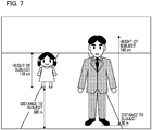
- Figs. 6 and 7 are diagrams illustrating examples of images displayed on the imaged screen, and in a case in which a plurality of subjects having different heights are present at different distances as illustrated in Figs. 6 and 7 or the like, the subjects may be out of focus.
- optimal control may not be able to be performed using only tilt control in many cases.
- Fig. 8 is a diagram illustrating focus lens driving and tilt control.
- x is an amount of focus correction (an amount of defocusing) from an imaging plane of the imaging optical system that should be reduced to be zero for focusing on the subject person 801.
- y is an amount of focus correction (an amount of defocusing) from a focal plane of the imaging optical system that should be reduced to be zero for focusing on the subject vehicle 802. In many cases, it may be difficult to focus on both the subject person 801 and the subject vehicle 802 only by performing tilt control.
- a distance (an image height) from a tilt axis passing through the center of the imaging plane of the imaging device 106 to a subject image will be denoted by k1 [ ⁇ m] for the subject person 801 and k2 [ ⁇ m] for the subject vehicle 802.
- k1 and k2 respectively correspond to the position information of a first area of the image screen and the position information of a second area of the image screen.
- ⁇ an amount of focus correction on an imaging plane according to movement of the focus lens 102
- ⁇ there is a method of calculating ⁇ from a product of sensitivity of the focus lens 102 and a drive amount of the focus lens 102.
- ⁇ ⁇ /(sensitivity of the focus lens).
- an equation of a higher degree or a polynomial according to sensitivity may be solved.
- the method of calculating the focus lens driving amount y can be variously modified or approximated, or the like, and a calculation method using such a modification, an approximation, or the like may be employed.
- Fig. 9 is a diagram illustrating focus lens driving and tilt control in a case in which there are three or more subjects on the image screen. In a case in which there are subjects positioned at a short distance and a long distance as in Fig. 9 , all the subjects may not be focused on by performing only tilt control and focus lens driving.
- Amounts of focus correction (defocus amounts; blur amounts) from the focal plane of the imaging optical system for a subject person 901 positioned at a long distance, and a subject person 902 positioned at a middle distance, and a subject person 903 positioned at a short distance will be respectively denoted by a [ ⁇ m], b [ ⁇ m], and c [ ⁇ m].
- a control method in this case will be described.
- a first method there is a method in which a maximum value of the amounts of focus correction such as a [ ⁇ m], b [ ⁇ m], c [ ⁇ m], and the like is controlled to be a minimum.
- a maximum value of a [ ⁇ m], b [ ⁇ m], and c [ ⁇ m] is controlled to be a minimum. According to this method, blurring of subjects in the scene as in Fig. 9 can be suppressed to be a minimum.
- a permissible focus range that is a depth of field
- the amounts of focus correction such as a [ ⁇ m], b [ ⁇ m], and c [ ⁇ m] are controlled to be within the depth of field.
- the depth of field is a value that is determined using a cell pitch per pixel of the imaging device 106 and an aperture value.
- F ⁇ the depth of field
- ⁇ and ⁇ are calculated by solving Equations 6 to 8 described above, and a tilt angle ⁇ and a focus lens driving amount y is calculated from ⁇ and ⁇ .
- a user does not perceive blurring of the image and does not need to make a maximum value of a [ ⁇ m], b [ ⁇ m], and c [ ⁇ m] to be a minimum as in the first method.
- control is performed using the second method, and if a subject to be focused is not within the depth of field, the control for driving using the first method may also be used.
- the long-distance side has a larger depth of field for the tilt control, and accordingly, it is also effective to perform tilt control and focus lens driving with a subject at a short distance with priority. For this reason, by using a distance measuring unit that measures a distance to a subject, distances to a plurality of subjects may be measured, and tilt control and focus lens driving may be performed for a subject that is relatively close to the imaging device with priority.
- disappearance may also be considered as a change in the subject.
- a method to cope with those cases should be taken into consideration.
- Fig. 10 is a diagram illustrating an example of a representative plane desired to be focused on in a case in which there is no subject or the like.
- a plane desired to be focused on may be set to a plane shifted, for example, by 1.6 m above the ground or the like, assuming the main subject is a person or the like.
- a plane desired to be focused on may be a plane that is determined by a user or a plane that is determined in advance.
- control modes for performing focus correction using at least one of the tilt control unit and the focus lens driving unit described above.
- one of the plurality of control modes is selected in accordance with the number of subject areas displayed on the image screen.
- Scanning is performed in S1101.
- the scanning is control of driving such that the tilt angle of the imaging device 106 or the position of the focus lens 102 is gradually changed in one direction.
- the focus evaluation value calculating unit 112 calculates an evaluation value for each area among a plurality of areas displayed on the image screen during the scanning.
- the subject determining unit 113 determines areas in which a subject is present.
- An area in which a subject is present is an area of which an evaluation value calculated for each area in S1102 is high or an area in which a subject to be focused such as a person or a vehicle is found by image recognition.
- the number of areas in which a subject is present (the number of subject areas displayed on the image screen) is determined.
- the number of subject areas is determined to be one in S1104, a first control mode is selected in S1105, in which focus correction is performed using one of tilt control and focus lens driving such that the area in which a subject is present is focused on.
- focus correction is performed using tilt control.
- tilt control is performed in a case in which a distance (an image height) to a subject from the vertical center on the image screen is longer than a predetermined value
- focus correction is performed using focus lens driving in a case in which the distance (the image height) to a subject from the vertical center of the image screen is shorter than the predetermined value.
- a second control mode is selected in S1106.
- focus correction is performed using both tilt control and focus lens driving. More specifically, for example, the amounts of focus correction is calculated such that both the areas in which subjects are present are focused on by using Equations 2 to 5 as described above.
- the position of the focus lens at which the evaluation value for each area becomes a peak value is acquired, for example, as x and y represented in Equations 2 and 3.
- k1 and k2 represented in Equations 2 and 3 are acquired on the basis of the position of the area on the image screen.
- a tilt angle ⁇ and a focus lens driving amount ⁇ are calculated using Equations 4 and 5.
- tilt control and focus lens driving are performed based on the tilt angle ⁇ and the focus lens driving amount ⁇ described above.
- a method for calculating a focus correction amount for each area is not limited to the method described above, and a distance to a subject may be acquired using an external measurement sensor or an image-plane-phase-difference image sensor in which each pixel includes a plurality of photoelectric conversion units having a parallax therebetween.
- the second control mode is selected in S1107.
- focus correction is performed using both the tilt control and the focus lens driving.
- a specific calculation method (calculation algorithm) is different from S1106.
- a tilt angle ⁇ and a focus lens driving amount ⁇ are calculated, for example, using Equations 6 to 8 such that a maximum value of the amount of focus correction (the amount of blurring) of the area in which a subject is present becomes a minimum.
- tilt control and focus lens driving are performed based on the tilt angle ⁇ and the focus lens driving amount ⁇ that have been calculated by the above method.
- Step S1107 control is performed such that the area in which the subject is present comes into a diameter of permissible circle of confusion.
- the process proceeds to Step S1107 in a case in which the number of areas in which a subject is present is equal to or larger than a predetermined number "three", the predetermined number may be, for example, equal to or larger than "four". In such a case, where the number of areas in which a subject is present is two or three, the process proceeds to S1106. As another embodiment, in a case where the number of areas in which a subject is present is equal to or larger than two, the process may proceed to Step S1107, and Step S1106 may be omitted.
- a third control mode is selected in S1108, where control is performed such that an amount of focus correction set in advance is used.
- the focus lens driving position and the tilt angle are returned to the focus lens driving position and the tilt angle in the past that are immediately before the start of control such as scanning.
- a most-frequently stopped position in focus lens driving and tilt control in the past may be stored, and focus lens driving and tilt control may be performed using the most-frequently stopped position as a default.
- a history of focus lens driving positions and tilt angles in the past and the amounts of focus corrections in the past is stored in a memory, and the focus position and the tilt angle are controlled on the basis of the history information.
- control similar to that of a case in which there is no area in which a subject is present may be performed.
- the number of subject areas on the image screen is automatically determined in S1103. Then, one of a plurality of control modes for focus corrections using at least one of the tilt control unit and the focus lens driving unit is selected in accordance with the number. Accordingly, the subject does not become out of focus depending on a change in the subject, and tilt control and focus lens driving optimal for the situation can be realized.
- Embodiment 2 of the present invention will be described with reference to Fig. 12 .
- arbitrary areas of a captured image are designated by a user, and a focus position and a tilt angle are controlled.
- Fig. 12 is a diagram illustrating one example of an imaging scene according to Embodiment 2.
- a user designates these two areas using an area designating unit (a touch panel, a mouse, or the like).
- the user sets designation areas by designating an area itself, a corner, a width, a height, and the like of each area using the area designating unit.
- a predetermined frame having a predetermined size may be displayed on the image screen in advance, and the frame may be moved to an arbitrary position to designate a position and the determination operation is carried out.
- a first designation area 1203 can be easily set, and subsequently, a second designation area 1204 can be also easily set similarly.
- subject areas on the image screen may be manually designated by the user.
- the number of subject areas on the image screen that are designated by the user corresponds to the number of areas in which a subject is present in Step S1104.
- Embodiment 2 after subject areas on the image screen are manually designated by the user, the number of areas in which a subject is present is determined in Step S1104. However, in Embodiment 3, a tilt angle and a focus position are controlled without determining the number of areas.
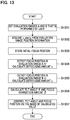
- Fig. 13 is a flowchart illustrating one example of a process flow according to Embodiment 3.
- a user sets arbitrary two designation areas including a designation area A (a first area) (1203) and a designation area B (a second area) (1204) as illustrated in Fig. 12 .
- the designation area A will be referred to as an evaluation range A
- the designation area B will be referred to as an evaluation range B.
- S1302 functions as a position information acquiring unit that acquires position information of the first area from a vertical center of the image screen and position information of the second area from a vertical center of the image screen.
- S1303 functions as a defocusing amount detecting unit that detects a defocusing amount of each of the first area and the second area.
- the calculation method is the same as described in Embodiment 1.
- tilt control can be performed by controlling the tilt angle and the focus position in S1307.
- designation areas have a rectangular shape in this embodiment, any designation method and any shape may be employed as long as the purpose of designation of areas can be achieved.
- a tilt angle of the imaging device is changed in the tilt control
- a tilt angle of the lens may be changed.
- not only the tilt control in the horizontal direction but also tilt control in a vertical direction may be used.
- Embodiments 1 to 3 described above an example in which a calculation result is derived by performing calculation using a CPU or the like using equations has been described. However, instead of calculation using equations, a table corresponding to such equations may be stored in a memory, and a result similar to the calculation result based on the equations may be directly derived using the table.
- a computer program realizing the function of the embodiment described above may be supplied to the imaging apparatus or the imaging control device through a network or various storage media. Then, a computer (or a CPU, an MPU, or the like) of the imaging apparatus or the image control device may be configured to read and execute the program. In such a case, the program and the storage medium storing the program configure the present invention.
- an imaging apparatus including a tilt control unit that performs tilt control by driving at least one of an imaging device and an imaging optical system, a focus lens driving unit that drives a focus lens, and a control unit that has a plurality of control modes for performing focus correction using at least one of the tilt control unit and the focus lens driving unit and selects one of the plurality of control modes in accordance with the number of subject areas displayed on an image screen.
Landscapes
- Engineering & Computer Science (AREA)
- Multimedia (AREA)
- Signal Processing (AREA)
- Physics & Mathematics (AREA)
- General Physics & Mathematics (AREA)
- Computing Systems (AREA)
- Theoretical Computer Science (AREA)
- Optics & Photonics (AREA)
- Human Computer Interaction (AREA)
- Studio Devices (AREA)
- Automatic Focus Adjustment (AREA)
- Focusing (AREA)
- Lens Barrels (AREA)
- Closed-Circuit Television Systems (AREA)
Abstract
Description
- The present invention relates to an imaging apparatus and the like capable of performing tilt control.
- Conventionally, there are cases in which passersby on the roadside are monitored, or vehicles or number plates thereof are imaged by installing a monitoring camera at a high place such as under the eaves and directing an optical axis of the camera obliquely downward. In such cases, since the optical axis of the camera is obliquely downward, a focused plane that is in focus when imaging is performed is a plane vertical to the optical axis and does not coincide with an imaging plane of a subject that is a target for actual imaging in many cases.
- For this reason, an area that is in focus is a part of the screen, and other areas are out of focus.
- Regarding such a problem, an imaging apparatus to which the Scheimpflug principle for broadening the range of the depth of field by performing control of relatively inclining a lens or an imaging device (hereinafter referred to as tilt control) is applied is generally known.
- However, when tilt control at a predetermined angle is performed for both of a subject at a short distance and a subject at a long distance, there may be differences between heights of positions of the subjects, differences between heights of the subjects themselves, or the like, and therefore there may be a plurality of tilt angles for focusing both of the subject at a short distance and the subject at a long distance. For this reason, tilt control for focusing on both of subjects positioned at a short distance and subjects positioned at a long distance cannot be performed with only one tilt angle. It is important for a monitoring camera to recognize subjects from a short distance and a long distance.
- In addition, when a position of a subject changes, it is necessary to perform appropriate tilt control in accordance with the change of the position of the subject. In such a case, although one subject among a plurality of subjects may be focused on by controlling only the tilt angle, subjects positioned in a plurality of areas cannot be focused on in that way. For this reason, it is necessary not only to change the tilt angle but also to control a position of a focus lens.
- In Japanese Patent Laid-Open No.
11-242154 - However, in the imaging apparatus described in Japanese Patent Laid-Open No.
11-242154 - An object of the present invention is to provide an imaging apparatus capable of performing optimal tilt control at a high speed by optimizing focus lens driving and tilt control even in a case in which a subject changes or the like.
- In order to achieve the object described above, according to one aspect of the present invention, there is provided an imaging apparatus including: a tilt control unit that performs tilt control by driving at least one of an imaging device and an imaging optical system; a focus lens driving unit that drives a focus lens; and a control unit that has a plurality of control modes for performing focus correction using at least one of the tilt control unit and the focus lens driving unit and selects one of the plurality of control modes in accordance with the number of subject areas on an image screen.
- Further features of the present invention will become apparent from the following description of exemplary embodiments with reference to the attached drawings.
-
-
Fig. 1 is a block diagram illustrating an example of the configuration of an imaging apparatus according to Embodiment 1 of the present invention. -
Fig. 2 is a diagram illustrating an example of a scene on which tilt control is performed. -
Fig. 3 is a diagram illustrating a tilt control method. -
Fig. 4 is a diagram illustrating Example 1 in which a plurality of tilt angles are present. -
Fig. 5 is a diagram illustrating Example 2 in which a plurality of tilt angles are present. -
Fig. 6 is a diagram illustrating an example of an imaging scene. -
Fig. 7 is a diagram illustrating another example of an imaging scene. -
Fig. 8 is a diagram illustrating focus lens driving and tilt control according to Embodiment 1 of the present invention. -
Fig. 9 is a diagram illustrating focus lens driving and tilt control in a case in which there are three or more subjects. -
Fig. 10 is a diagram illustrating an example of a representative plane desired to be focused on in a case in which there is no subject or the like. -
Fig. 11 is a flowchart illustrating a plurality of control modes according to Embodiment 1 of the present invention. -
Fig. 12 is a diagram illustrating one example of an imaging scene according to Embodiment 2. -
Fig. 13 is a flowchart illustrating one example of a process flow according to Embodiment 3. - Hereinafter, preferred embodiments of the present invention will be described in detail using embodiments with reference to the attached drawings.
-
Fig. 1 is a block diagram illustrating the configuration of an imaging apparatus according to Embodiment 1 of the present invention. - A lens unit that is an imaging optical system according to this embodiment includes a
zoom lens 101 that changes a focal distance by moving in the direction of an optical axis, afocus lens 102 that performs control of focus by moving in the direction of the optical axis, and adiaphragm unit 103 that adjusts an amount of light entering on animaging device 106. The imaging optical system illustrated inFig. 1 is one example, and thezoom lens 101, thefocus lens 102, and thediaphragm unit 103 need not all be included. - Light passed through the imaging optical system forms a subject image as an optical image on an
imaging device 106 through a bandpass filter (hereinafter referred to as a BPF) 104 and acolor filter 105. - The BPF 104 may be selectively retracted from an optical path of the imaging optical system. A subject image is photoelectrically converted by the
imaging device 106, whereby an imaging signal is formed. - An analog imaging signal output from the
imaging device 106 is gain adjusted by auto gain control (AGC) 107, is converted into a digital signal by anAD converter 108, and then is input to a camerasignal processing unit 109. - The camera
signal processing unit 109 performs various kinds of image processing (for example, gamma conversion, white balance adjustment, and the like) for a digital imaging signal, thereby generating a video signal. By displaying this video signal as an image on a display unit included in amonitor device 111, an image screen can be displayed as shown inFigs. 6 ,7 ,10 , and12 . - The video signal is output to at least one
monitor device 111 through a network using wired or wireless communication via acommunication unit 110. In addition, thecommunication unit 110 receives a command from an external control device such as an external PC included in themonitor device 111 and transmits a control signal corresponding to the command to a tilt/focus control unit 115 of the imaging apparatus. - In this embodiment, a system including the
monitor device 111 and the like will be referred to as an imaging apparatus. InFig. 1 of this embodiment, members other than themonitor device 111 are housed inside one casing and configure a security camera. - A focus evaluation
value calculating unit 112 receives pixel values or luminance values of RGB from theAD converter 108 or the camerasignal processing unit 109 and calculates a focus evaluation value used for tilt control or auto focusing (hereinafter referred to as AF). For example, by dividing an image screen displayed on a display unit of themonitor device 111 into a plurality of subject areas, the focus evaluation value is calculated on the basis of contrast and high-frequency components of the image for each subject area. The focus evaluation value may be acquired using any method such as a phase difference AF method, an infrared AF method, or the like as long as the focus evaluation value can be used for focus adjustment. - In addition, for example, a display unit for displaying an image screen may be selectively connected to an output side of the camera
signal processing unit 109 and may allow the image screen to be monitored also on the security camera side. - A
subject determining unit 113 performs an image recognition on a video signal from the camerasignal processing unit 109 and detects a specific subject on the image screen. The specific subject is a subject (for example, a person, a face, a vehicle, or the like) that is arbitrarily designated by a user or is set as a default in advance but is not limited to such examples. - A focus evaluation value from the focus evaluation
value calculating unit 112 and a subject recognition result from thesubject determining unit 113 are input to a tilt/focus lens drivingamount calculating unit 114. In addition, the tilt/focus lens drivingamount calculating unit 114 calculates a tilt angle and a focus position that are optimal to a scene based on the focus evaluation value, the subject recognition result, and the tilt angle information and the focus position information from the tilt/focus control unit 115. The tilt angle and the focus position are controlled by transmitting the tilt angle and the focus position that have been calculated to the tilt/focus control unit 115. - The tilt/
focus control unit 115 has a CPU as a computer and executes various operations of the entire apparatus as a control unit on the basis of a computer program stored in a memory that is not illustrated in the drawing. The tilt/focus control unit 115 performs focus lens driving in AF or manual focus (hereinafter referred to as MF) on the basis of a direction from an external control device such as the external PC through thecommunication unit 110. In addition, the tilt/focus control unit 115 receives the current lens position information from an imagingdevice driving unit 116 and afocus driving unit 117, and transmits the current position to the tilt/focus lens drivingamount calculating unit 114. Furthermore, the tilt/focus control unit 115 performs drive control by sending the tilt angle and the focus position calculated by the tilt/focus lens drivingamount calculating unit 114 to the imagingdevice driving unit 116 and thefocus driving unit 117. - The imaging
device driving unit 116 functions as a tilt control unit (a tilt angle control unit) and tilts theimaging device 106 on the basis of a tilt angle designated by the tilt/focus control unit 115. By inclining theimaging device 106, a tilt angle that is an angle between theimaging device 106 and a plane orthogonal to the optical axis of the imaging optical system is changed. - In this embodiment, a rotation axis (a tilt axis) for tilting the
imaging device 106 is arranged to pass through the center of the imaging plane in a horizontal direction (the longitudinal direction of the imaging device), around which theimaging device 106 is controlled to tilt relative to the imaging optical system. - In this connection, in order to perform tilt control, instead of tilting the imaging device, some lenses of the imaging optical system may be controlled to tilt relative to the imaging device.
- The
focus driving unit 117 controls the position of thefocus lens 102 on the basis of a focus setting position directed from the tilt/focus control unit 115. - As an example of a scene on which tilt control is performed, a scene illustrated in
Fig. 2 will be assumed.Fig. 2 is a diagram illustrating an example of a scene on which tilt control is performed. - A case in which there are subjects at a short distance and a long distance is illustrated. In a focusing operation in AF or MF without performing tilt control, either a subject positioned at a short distance or a subject positioned at a long distance is focused on.
-
Fig. 3 is a diagram illustrating a tilt control method, and tilt control, as illustrated inFig. 3 , is control for setting a (focused) plane that is focused on to be in parallel with a horizontal plane such as the ground, for example, by tilting theimaging device 106. In this way, with respect to a plane parallel to the ground, a subject positioned at a short distance and a subject positioned at a long distance enter the depth of field and can remain in focus. - A tilt angle b is calculated using the following Equation (1) based on the Scheimpflug principle.

- Here, f is a focal distance, L is a subject distance, and α is an angle between an optical axis and a focused plane.
-
Figs. 4 and5 are diagrams illustrating Examples 1 and 2 in which a plurality of optimal tilt angles are present. In a case in which a height of a surface on which a subject is walking changes as illustrated inFig. 4 , a case in which a plurality of subjects having different heights are present as illustrated inFig. 5 , or the like, an optimal tilt angle is different for each subject. Similarly, in a case in which a subject positioned at the center of an image screen, corresponding to the center of the imaging device through which a tilt rotation axis passes, is out of focus by AF or MF or the like, an optimal tilt angle is different for each subject. In other words, there are a plurality of optimal tilt angles for the subjects displayed on the image screen.Figs. 6 and7 are diagrams illustrating examples of images displayed on the imaged screen, and in a case in which a plurality of subjects having different heights are present at different distances as illustrated inFigs. 6 and7 or the like, the subjects may be out of focus. - Furthermore, even in a case in which each subject moves or disappears in accordance with elapse of time, there are cases in which the subjects are out of focus in accordance with the change in the scene in conventional tilt control.
- In addition, in a case in which there are a plurality of subjects having different heights, optimal control may not be able to be performed using only tilt control in many cases.
- One example thereof will be described with reference to
Fig. 8. Fig. 8 is a diagram illustrating focus lens driving and tilt control. - A case in which there are a subject person 801 (a first area) and a subject vehicle 802 (a second area) on a screen as target subjects will be considered. A current tilt angle and the position of the
focus lens 102 have a positional relation illustrated in an upper part ofFig. 8 . Here, x is an amount of focus correction (an amount of defocusing) from an imaging plane of the imaging optical system that should be reduced to be zero for focusing on thesubject person 801. In addition, y is an amount of focus correction (an amount of defocusing) from a focal plane of the imaging optical system that should be reduced to be zero for focusing on thesubject vehicle 802. In many cases, it may be difficult to focus on both thesubject person 801 and thesubject vehicle 802 only by performing tilt control. - For this reason, in this embodiment, focus correction using a focus lens and focus correction using tilt control are performed together. An example of a method of calculating driving amounts thereof in this case will be described. As in the upper part of
Fig. 8 , a distance (an image height) from a tilt axis passing through the center of the imaging plane of theimaging device 106 to a subject image will be denoted by k1 [µm] for thesubject person 801 and k2 [µm] for thesubject vehicle 802. Here, k1 and k2 respectively correspond to the position information of a first area of the image screen and the position information of a second area of the image screen. In addition, an amount of focus correction on an imaging plane according to movement of thefocus lens 102 will be denoted by β. - As an example of the calculation of β, there is a method of calculating β from a product of sensitivity of the
focus lens 102 and a drive amount of thefocus lens 102. On the other hand, amounts of focus correction according to a tilt angle are products of α = tanθ and distances k1 and k2 from the tilt axis to the subject images when the tilt angle is denoted by θ [°]. - Thus, the following equations are obtained.


- By solving the simultaneous equations, the followings are acquired.


- Accordingly, the tilt angle θ can be calculated using the following equation.

- In addition, for example, in order to approximately calculate the amount of driving of the focus lens (a focus lens driving amount) y, it can be calculated using γ=β/(sensitivity of the focus lens). Furthermore, for more accurate calculation, an equation of a higher degree or a polynomial according to sensitivity may be solved.
- The method of calculating the focus lens driving amount y can be variously modified or approximated, or the like, and a calculation method using such a modification, an approximation, or the like may be employed.
- A case in which there are three or more subjects on the image screen will be described.
Fig. 9 is a diagram illustrating focus lens driving and tilt control in a case in which there are three or more subjects on the image screen. In a case in which there are subjects positioned at a short distance and a long distance as inFig. 9 , all the subjects may not be focused on by performing only tilt control and focus lens driving. - Amounts of focus correction (defocus amounts; blur amounts) from the focal plane of the imaging optical system for a
subject person 901 positioned at a long distance, and asubject person 902 positioned at a middle distance, and asubject person 903 positioned at a short distance will be respectively denoted by a [µm], b [µm], and c [µm]. - An example of a control method in this case will be described. First, as a first method, there is a method in which a maximum value of the amounts of focus correction such as a [µm], b [µm], c [µm], and the like is controlled to be a minimum. By performing focus lens driving and tilt control, a maximum value of a [µm], b [µm], and c [µm] is controlled to be a minimum. According to this method, blurring of subjects in the scene as in
Fig. 9 can be suppressed to be a minimum. As a second method, there is a method in which a permissible focus range, that is a depth of field, is calculated, and the amounts of focus correction such as a [µm], b [µm], and c [µm] are controlled to be within the depth of field. - The depth of field is a value that is determined using a cell pitch per pixel of the
imaging device 106 and an aperture value. When the depth of field is denoted by FΔ, it can be calculated by solving the following equations.


- α and β are calculated by solving Equations 6 to 8 described above, and a tilt angle θ and a focus lens driving amount y is calculated from α and β.
- In a case in which a [µm], b [µm], and c [µm] are within the depth of field, a user does not perceive blurring of the image and does not need to make a maximum value of a [µm], b [µm], and c [µm] to be a minimum as in the first method. In a case in which control is performed using the second method, and if a subject to be focused is not within the depth of field, the control for driving using the first method may also be used.
- Generally, comparing the depth of fields at a short distance and a long distance, the long-distance side has a larger depth of field for the tilt control, and accordingly, it is also effective to perform tilt control and focus lens driving with a subject at a short distance with priority. For this reason, by using a distance measuring unit that measures a distance to a subject, distances to a plurality of subjects may be measured, and tilt control and focus lens driving may be performed for a subject that is relatively close to the imaging device with priority.
- In addition, disappearance may also be considered as a change in the subject. In such a case, there is a possibility of erroneous focusing on a plane of the ground or the like. In addition, since there is also a case where a plane different from a preferable focused plane desired to be focused on may be erroneously set, a method to cope with those cases should be taken into consideration.
-
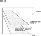
Fig. 10 is a diagram illustrating an example of a representative plane desired to be focused on in a case in which there is no subject or the like. As inFig. 10 , in accordance with a background scene when a security camera is installed and a main target subject of the security camera, for example, a plane desired to be focused on may be set to a plane shifted, for example, by 1.6 m above the ground or the like, assuming the main subject is a person or the like. By performing control such that the plane described above is set, a ratio of a focused area within the screen can be increased. In other words, large blurring can be prevented. A plane desired to be focused on may be a plane that is determined by a user or a plane that is determined in advance. In addition, a method in which, by reading a history from a memory, frequently stopped positions of the focus lens and tilt angles in the past may be obtained, then by weighting them, the positions and the tilt angles suitable to the scene may be realized. - Next, an example of selecting a plurality of control modes according to Embodiment 1 will be described with reference to a flowchart illustrated in
Fig. 11 . - In this embodiment, there are a plurality of control modes for performing focus correction using at least one of the tilt control unit and the focus lens driving unit described above. In addition, there is a feature in that one of the plurality of control modes is selected in accordance with the number of subject areas displayed on the image screen.
- Scanning is performed in S1101. The scanning is control of driving such that the tilt angle of the
imaging device 106 or the position of thefocus lens 102 is gradually changed in one direction. In S1102, the focus evaluationvalue calculating unit 112 calculates an evaluation value for each area among a plurality of areas displayed on the image screen during the scanning. - In S1103, the
subject determining unit 113 determines areas in which a subject is present. An area in which a subject is present is an area of which an evaluation value calculated for each area in S1102 is high or an area in which a subject to be focused such as a person or a vehicle is found by image recognition. - In S1104, the number of areas in which a subject is present (the number of subject areas displayed on the image screen) is determined. In a case in which the number of subject areas is determined to be one in S1104, a first control mode is selected in S1105, in which focus correction is performed using one of tilt control and focus lens driving such that the area in which a subject is present is focused on.
- More specifically, for example, in a case in which there is no subject near the vertical center of the image screen, focus correction is performed using tilt control. In other words, tilt control is performed in a case in which a distance (an image height) to a subject from the vertical center on the image screen is longer than a predetermined value, and focus correction is performed using focus lens driving in a case in which the distance (the image height) to a subject from the vertical center of the image screen is shorter than the predetermined value.
- In a case in which the number of areas in which a subject is present is two in S1104, a second control mode is selected in S1106. In the second control mode, focus correction is performed using both tilt control and focus lens driving. More specifically, for example, the amounts of focus correction is calculated such that both the areas in which subjects are present are focused on by using Equations 2 to 5 as described above.
- In other words, by using an evaluation value for each area calculated in S1102, the position of the focus lens at which the evaluation value for each area becomes a peak value is acquired, for example, as x and y represented in Equations 2 and 3. k1 and k2 represented in Equations 2 and 3 are acquired on the basis of the position of the area on the image screen. Then, a tilt angle θ and a focus lens driving amount γ are calculated using Equations 4 and 5.
- Subsequently, tilt control and focus lens driving are performed based on the tilt angle θ and the focus lens driving amount γ described above.
- In this connection, a method for calculating a focus correction amount for each area is not limited to the method described above, and a distance to a subject may be acquired using an external measurement sensor or an image-plane-phase-difference image sensor in which each pixel includes a plurality of photoelectric conversion units having a parallax therebetween.
- In a case in which it is determined that the number of areas in which a subject is present is three or more in S1104, similar to S1106, the second control mode is selected in S1107. In other words, focus correction is performed using both the tilt control and the focus lens driving. Here, although the same second control mode is selected, a specific calculation method (calculation algorithm) is different from S1106. As described above, a tilt angle θ and a focus lens driving amount γ are calculated, for example, using Equations 6 to 8 such that a maximum value of the amount of focus correction (the amount of blurring) of the area in which a subject is present becomes a minimum. Then, tilt control and focus lens driving are performed based on the tilt angle θ and the focus lens driving amount γ that have been calculated by the above method.
- In this case, control is performed such that the area in which the subject is present comes into a diameter of permissible circle of confusion. Although the process proceeds to Step S1107 in a case in which the number of areas in which a subject is present is equal to or larger than a predetermined number "three", the predetermined number may be, for example, equal to or larger than "four". In such a case, where the number of areas in which a subject is present is two or three, the process proceeds to S1106. As another embodiment, in a case where the number of areas in which a subject is present is equal to or larger than two, the process may proceed to Step S1107, and Step S1106 may be omitted.
- In a case in which there is no area in which a subject is present in S1104, in other words, when it is determined that no subject is present on the image screen, a third control mode is selected in S1108, where control is performed such that an amount of focus correction set in advance is used. In other words, the focus lens driving position and the tilt angle are returned to the focus lens driving position and the tilt angle in the past that are immediately before the start of control such as scanning. Alternatively, a most-frequently stopped position in focus lens driving and tilt control in the past may be stored, and focus lens driving and tilt control may be performed using the most-frequently stopped position as a default. In other words, a history of focus lens driving positions and tilt angles in the past and the amounts of focus corrections in the past is stored in a memory, and the focus position and the tilt angle are controlled on the basis of the history information.
- In addition, also in a case in which there is no change in the area of the subject, control similar to that of a case in which there is no area in which a subject is present may be performed.
- As described above, in Embodiment 1, the number of subject areas on the image screen is automatically determined in S1103. Then, one of a plurality of control modes for focus corrections using at least one of the tilt control unit and the focus lens driving unit is selected in accordance with the number. Accordingly, the subject does not become out of focus depending on a change in the subject, and tilt control and focus lens driving optimal for the situation can be realized.
- Next, Embodiment 2 of the present invention will be described with reference to
Fig. 12 . In Embodiment 2, arbitrary areas of a captured image are designated by a user, and a focus position and a tilt angle are controlled. -
Fig. 12 is a diagram illustrating one example of an imaging scene according to Embodiment 2. For a subject A1201 and a subject B1202 shown inFig. 12 , a user designates these two areas using an area designating unit (a touch panel, a mouse, or the like). In this embodiment, the user sets designation areas by designating an area itself, a corner, a width, a height, and the like of each area using the area designating unit. - In addition, as another method, a predetermined frame having a predetermined size may be displayed on the image screen in advance, and the frame may be moved to an arbitrary position to designate a position and the determination operation is carried out. By using the method as described above, for example, a
first designation area 1203 can be easily set, and subsequently, asecond designation area 1204 can be also easily set similarly. - In this way, instead of executing automatic determination of subject areas on the image screen in Steps S1101 to S1103 as illustrated in
Fig. 11 , subject areas on the image screen may be manually designated by the user. In such a case, the number of subject areas on the image screen that are designated by the user corresponds to the number of areas in which a subject is present in Step S1104. - In Embodiment 2, after subject areas on the image screen are manually designated by the user, the number of areas in which a subject is present is determined in Step S1104. However, in Embodiment 3, a tilt angle and a focus position are controlled without determining the number of areas.
-
Fig. 13 is a flowchart illustrating one example of a process flow according to Embodiment 3. - First, in S1301, as described above, a user sets arbitrary two designation areas including a designation area A (a first area) (1203) and a designation area B (a second area) (1204) as illustrated in
Fig. 12 . Here, the designation area A will be referred to as an evaluation range A, and the designation area B will be referred to as an evaluation range B. - Next, in S1302, k1 and k2 described in Embodiment 1 are acquired from image heights of the two designation areas (evaluation ranges). In other words, a distance (image height) from the tilt axis passing through the center of the imaging plane of the
imaging device 106 to the center of the evaluation range A will be denoted by k1 [µm], and a distance (image height) from the tilt axis to the center of the evaluation range B will be noted by k2 [µm]. In other words, S1302 functions as a position information acquiring unit that acquires position information of the first area from a vertical center of the image screen and position information of the second area from a vertical center of the image screen. - Then, an initial focus position is stored in S1303, an amount of correction (a defocusing amount from the focal plane) x for the evaluation range A is calculated in S1304, and subsequently, an amount of correction (a defocusing amount from the focal plane) y for the evaluation range B is calculated in S1305. In other words, S1303 functions as a defocusing amount detecting unit that detects a defocusing amount of each of the first area and the second area.
- The calculation method is the same as described in Embodiment 1.
- In S1306, a tilt angle θ and a focus correction amount β are calculated.
- The tilt angle θ, as described in Embodiment 1, is acquired as θ = arctan((x+y)/(k1+k2)) using Equation 6.
- On the basis of values of the calculation results described above, tilt control can be performed by controlling the tilt angle and the focus position in S1307.
- In this Embodiment 3, although a case in which there are two subjects has been illustrated, by selecting an arbitrary subject from among a plurality of subjects, the subject desired to be focused by the user can be also focused on.
- In addition, a process performed in a case in which the number of selected areas is larger than two or the number of selected areas is smaller than two, which has not been described in this embodiment, can be handled by a process similar to that in the case of a plurality of focus positions described in Embodiment 1.
- Although the designation areas have a rectangular shape in this embodiment, any designation method and any shape may be employed as long as the purpose of designation of areas can be achieved.
- In Embodiments 1 to 3 described above, for example, although a tilt angle of the imaging device is changed in the tilt control, a tilt angle of the lens may be changed. In addition, not only the tilt control in the horizontal direction but also tilt control in a vertical direction may be used.
- In addition, in Embodiments 1 to 3 described above, an example in which a calculation result is derived by performing calculation using a CPU or the like using equations has been described. However, instead of calculation using equations, a table corresponding to such equations may be stored in a memory, and a result similar to the calculation result based on the equations may be directly derived using the table.
- The present invention is not limited to the embodiments described above, various modifications can be made on the basis of the main concept of the present invention, and such modifications are not intended to be excluded from the scope of the present invention.
- In addition, as a part or the whole of the control according to this embodiment, a computer program realizing the function of the embodiment described above may be supplied to the imaging apparatus or the imaging control device through a network or various storage media. Then, a computer (or a CPU, an MPU, or the like) of the imaging apparatus or the image control device may be configured to read and execute the program. In such a case, the program and the storage medium storing the program configure the present invention.
- While the present invention has been described with reference to exemplary embodiments, it is to be understood that the invention is not limited to the disclosed exemplary embodiments. The scope of the following claims is to be accorded the broadest interpretation so as to encompass all such modifications and equivalent structures and functions.
- This application claims the benefit of Japanese Patent Application No.
2019-48401 filed on Mar 15, 2019 2019-204141 filed on Nov 11, 2019 - In order to provide a tilt control device that is optimal at a high speed by controlling both a focus position and a tilt angle even when a scene changes such as in a case in which a subject changes, there is provided an imaging apparatus including a tilt control unit that performs tilt control by driving at least one of an imaging device and an imaging optical system, a focus lens driving unit that drives a focus lens, and a control unit that has a plurality of control modes for performing focus correction using at least one of the tilt control unit and the focus lens driving unit and selects one of the plurality of control modes in accordance with the number of subject areas displayed on an image screen.
Claims (19)
- An imaging apparatus comprising:a tilt control unit that performs tilt control by driving at least one of an imaging device and an imaging optical system;a focus lens driving unit that drives a focus lens; anda control unit that has a plurality of control modes for performing focus correction using at least one of the tilt control unit and the focus lens driving unit and selects one of the plurality of control modes in accordance the number of subject areas displayed on an image screen.
- The imaging apparatus according to claim 1, wherein the control unit calculates an amount of focus correction from a focal plane of the imaging optical system.
- The imaging apparatus according to claim 2, wherein the control unit calculates the amount of focus correction on the basis of a distance from a position of a tilt axis on the image screen.
- The imaging apparatus according to claim 1, wherein the control unit calculates an amount of driving of the focus lens on the basis of sensitivity of the focus lens.
- The imaging apparatus according to claim 1, wherein, in a case in which the number of subject areas displayed on the image screen is one, the control unit selects a first control mode in which focus correction is performed using one of the tilt control unit and the focus lens driving unit.
- The imaging apparatus according to claim 1, wherein, in a case in which the number of subject areas displayed on the image screen is equal to or larger than two, the control unit selects a second control mode in which focus correction is performed for the subject using the tilt control unit and the focus lens driving unit.
- The imaging apparatus according to claim 2, wherein, in a case in which there is no subject area displayed on the image screen, the control unit selects a third control mode in which a predetermined amount of focus correction is performed.
- The imaging apparatus according to claim 7, wherein the predetermined amount of the focus correction is set in advance on the basis of a past history.
- The imaging apparatus according to claim 1, wherein the control unit performs control of the tilt control unit and the focus lens driving unit such that a maximum value of the amounts of focus correction for a plurality of subjects becomes smallest in a case in which the number of subject areas displayed on the image screen is equal to or larger than a predetermined number.
- The imaging apparatus according to claim 1, wherein the control unit performs control of the tilt control unit and the focus lens driving unit such that amounts of focus correction for a plurality of subjects are within a depth of field in a case in which the number of subject areas displayed on the image screen is equal to or larger than a predetermined number.
- The imaging apparatus according to claim 1, further comprising a distance measuring unit that measures a distance to a subject,
wherein the control unit performs control of the tilt control unit and the focus lens driving unit so that a subject relatively close to the imaging device is prioritized in a case in which the number of subject areas displayed on the image screen is equal to or larger than a predetermined number. - The imaging apparatus according to any one of claims 9 to 11, wherein the predetermined number is three.
- The imaging apparatus according to claim 1, further comprising an external control device that is used for communicating with the control unit through a network.
- The imaging apparatus according to claim 1, wherein the control unit automatically determines subject areas on the image screen.
- The imaging apparatus according to claim 1, further comprising an area designating unit that is used for allowing a user to designate subject areas displayed on the image screen.
- An imaging apparatus comprising:a tilt angle control unit that performs tilt control of changing a tilt angle that is an angle between an imaging device and a plane that is orthogonal to an optical axis of an imaging optical system by inclining the imaging device;a focus lens driving unit that drives a focus lens;a position information acquiring unit that acquires position information of a first area of an image screen and position information of a second area of the image screen;a defocusing amount detecting unit that detects defocusing amounts of the first area and the second area;a calculation unit that calculates the tilt angle and an amount of driving of the focus lens on the basis of the position information and the defocusing amounts of each of the first area and the second area; anda control unit that controls the tilt angle control unit to incline the imaging device to the tilt angle calculated by the calculation unit and controls the focus lens driving unit to drive the focus lens by the amount of driving of the focus lens calculated by the calculation unit.
- The imaging apparatus according to claim 16, wherein the control unit performs control of the tilt angle control unit and the focus lens driving unit such that the equation θ = arctan((x+y)/(k1+k2)) is satisfied, where θ is a tilt angle, x is a defocusing amount of the first area, y is a defocusing amount of the second area, and k1 and k2 are distances from a position corresponding to a tilt axis to the first and second areas on the image screen, wherein the tilt axis passes through the center of an imaging plane.
- An imaging control method comprising:a tilt control step of performing tilt control by driving at least one of an imaging device and an imaging optical system;a focus lens driving step of driving a focus lens; anda control step of having a plurality of control modes for performing focus correction using at least one of the tilt control step and the focus lens driving step and selecting one of the plurality of control modes in accordance with the number of subject areas displayed on an image screen.
- A non-transitory computer readable storage medium storing a computer program causing a computer to execute a control process comprising:a tilt control step of performing tilt control by driving at least one of an imaging device and an imaging optical system;a focus lens driving step of driving a focus lens; anda control step of having a plurality of control modes for performing focus correction using at least one of the tilt control step and the focus lens driving step and selecting one of the plurality of control modes in accordance with the number of subject areas displayed on an image screen.
Applications Claiming Priority (2)
| Application Number | Priority Date | Filing Date | Title |
|---|---|---|---|
| JP2019048401 | 2019-03-15 | ||
| JP2019204141A JP7433848B2 (en) | 2019-03-15 | 2019-11-11 | Imaging device, computer program, storage medium, and imaging control method |
Publications (2)
| Publication Number | Publication Date |
|---|---|
| EP3722871A1 true EP3722871A1 (en) | 2020-10-14 |
| EP3722871B1 EP3722871B1 (en) | 2023-01-18 |
Family
ID=69804606
Family Applications (1)
| Application Number | Title | Priority Date | Filing Date |
|---|---|---|---|
| EP20162323.8A Active EP3722871B1 (en) | 2019-03-15 | 2020-03-11 | Imaging apparatus, imaging control method, and storage medium |
Country Status (5)
| Country | Link |
|---|---|
| US (2) | US11381731B2 (en) |
| EP (1) | EP3722871B1 (en) |
| JP (2) | JP7433848B2 (en) |
| KR (1) | KR102874689B1 (en) |
| CN (1) | CN111698417B (en) |
Cited By (2)
| Publication number | Priority date | Publication date | Assignee | Title |
|---|---|---|---|---|
| EP3968624A1 (en) * | 2020-09-14 | 2022-03-16 | Canon Kabushiki Kaisha | Information processing apparatus, information processing method, and program |
| EP4250755A1 (en) * | 2022-03-22 | 2023-09-27 | Canon Kabushiki Kaisha | Control apparatus, lens apparatus, image pickup apparatus, camera system, control method, and program |
Families Citing this family (17)
| Publication number | Priority date | Publication date | Assignee | Title |
|---|---|---|---|---|
| KR102510704B1 (en) * | 2018-10-30 | 2023-03-16 | 캐논 가부시끼가이샤 | Imaging apparatus |
| JP7271159B2 (en) * | 2018-12-14 | 2023-05-11 | キヤノン株式会社 | CONTROL DEVICE, IMAGING DEVICE, LENS DEVICE, PROGRAM, AND CONTROL METHOD OF CONTROL DEVICE |
| JP7362360B2 (en) | 2019-08-29 | 2023-10-17 | キヤノン株式会社 | Control device, imaging device, lens device, and program |
| JP7305485B2 (en) | 2019-08-29 | 2023-07-10 | キヤノン株式会社 | CONTROL DEVICE, IMAGING DEVICE, LENS DEVICE, CONTROL METHOD, AND PROGRAM |
| JP7336330B2 (en) | 2019-09-24 | 2023-08-31 | キヤノン株式会社 | Control device, imaging device, control method, and program |
| JP7471799B2 (en) * | 2019-11-12 | 2024-04-22 | キヤノン株式会社 | Control device, imaging device, control method, and program |
| CN114095645B (en) * | 2020-08-24 | 2023-04-18 | 浙江大华技术股份有限公司 | Depth-of-field adjusting method, imaging device, and storage device |
| EP4002365A1 (en) * | 2020-11-18 | 2022-05-25 | Koninklijke Philips N.V. | Device and method for controlling a camera |
| JP7646389B2 (en) * | 2021-02-24 | 2025-03-17 | キヤノン株式会社 | IMAGING APPARATUS, COMPUTER PROGRAM, STORAGE MEDIUM, AND METHOD FOR CONTROLLING IMAGING APPARATUS |
| JP7293309B2 (en) * | 2021-03-17 | 2023-06-19 | キヤノン株式会社 | IMAGING DEVICE, CONTROL METHOD AND STORAGE MEDIUM |
| US11722769B2 (en) | 2021-03-17 | 2023-08-08 | Canon Kabushiki Kaisha | Image pickup apparatus, control method, and storage medium |
| JP7731692B2 (en) * | 2021-04-21 | 2025-09-01 | キヤノン株式会社 | Control device, imaging device, control method, and program |
| US12047681B2 (en) | 2021-04-21 | 2024-07-23 | Canon Kabushiki Kaisha | Image pickup apparatus including tilt driving portion, control method, and memory medium |
| US11722775B2 (en) * | 2021-08-17 | 2023-08-08 | Canon Kabushiki Kaisha | Image pickup apparatus and controlling method thereof |
| CN118891887A (en) * | 2022-03-24 | 2024-11-01 | 高通股份有限公司 | System and method for adaptive phase detection autofocus offset correction |
| JP2024171847A (en) | 2023-05-30 | 2024-12-12 | キヤノン株式会社 | Control device, optical device and imaging device |
| JP2026002375A (en) * | 2024-06-21 | 2026-01-08 | 株式会社Screenホールディングス | SUBSTRATE PROCESSING APPARATUS AND SUBSTRATE PROCESSING METHOD |
Citations (9)
| Publication number | Priority date | Publication date | Assignee | Title |
|---|---|---|---|---|
| JPH11190864A (en) * | 1997-12-25 | 1999-07-13 | Canon Inc | Imaging device with tilt mechanism, method, and storage medium |
| JPH11242154A (en) | 1998-12-09 | 1999-09-07 | Olympus Optical Co Ltd | Image pickup device |
| EP0984319A1 (en) * | 1998-07-08 | 2000-03-08 | Hewlett-Packard Company | Camera with keystone distortion correction |
| US20020080242A1 (en) * | 2000-07-04 | 2002-06-27 | Koji Takahashi | Image sensing system and its control method |
| JP2003185902A (en) * | 2002-10-24 | 2003-07-03 | Olympus Optical Co Ltd | Camera |
| JP2008205569A (en) * | 2007-02-16 | 2008-09-04 | Fujifilm Corp | Imaging apparatus and method |
| JP2015230414A (en) * | 2014-06-05 | 2015-12-21 | キヤノン株式会社 | Imaging device, control method and program |
| JP2019048401A (en) | 2017-09-08 | 2019-03-28 | キヤノンファインテックニスカ株式会社 | Recording device and recording method |
| JP2019204141A (en) | 2018-05-21 | 2019-11-28 | 京セラドキュメントソリューションズ株式会社 | Work presentation apparatus and work presentation program |
Family Cites Families (26)
| Publication number | Priority date | Publication date | Assignee | Title |
|---|---|---|---|---|
| JPH0437935A (en) | 1990-06-01 | 1992-02-07 | Hitachi Ltd | computer with cache memory |
| JPH04324843A (en) * | 1991-04-25 | 1992-11-13 | Canon Inc | Camera with tilt means |
| JP4297630B2 (en) | 2001-04-25 | 2009-07-15 | 株式会社リコー | Electronic imaging device |
| JP2003075716A (en) * | 2001-09-06 | 2003-03-12 | Nikon Corp | Imaging device |
| DE102005041431B4 (en) * | 2005-08-31 | 2011-04-28 | WÖHLER, Christian | Digital camera with swiveling image sensor |
| JP2008165142A (en) * | 2007-01-05 | 2008-07-17 | Elmo Co Ltd | Imaging apparatus and focus adjustment method |
| JP5109803B2 (en) * | 2007-06-06 | 2012-12-26 | ソニー株式会社 | Image processing apparatus, image processing method, and image processing program |
| KR101271641B1 (en) * | 2011-05-25 | 2013-06-11 | 에스엘 주식회사 | System for monitoring front side of vehicles |
| JP5627652B2 (en) * | 2012-06-06 | 2014-11-19 | キヤノン株式会社 | Imaging apparatus and control method thereof, and lens apparatus and control method thereof |
| JP5938281B2 (en) * | 2012-06-25 | 2016-06-22 | キヤノン株式会社 | Imaging apparatus, control method therefor, and program |
| JP2014155063A (en) * | 2013-02-08 | 2014-08-25 | Sharp Corp | Chart for resolution measurement, resolution measurement method, positional adjustment method for camera module, and camera module manufacturing method |
| KR20140102443A (en) * | 2013-02-14 | 2014-08-22 | 삼성전자주식회사 | Object tracking method using camera and camera system for object tracking |
| JP6304964B2 (en) * | 2013-07-31 | 2018-04-04 | キヤノン株式会社 | Information processing apparatus, control method thereof, and system |
| US9183620B2 (en) * | 2013-11-21 | 2015-11-10 | International Business Machines Corporation | Automated tilt and shift optimization |
| JP6312410B2 (en) * | 2013-11-25 | 2018-04-18 | オリンパス株式会社 | Alignment apparatus, microscope system, alignment method, and alignment program |
| JP6635764B2 (en) * | 2015-11-18 | 2020-01-29 | キヤノン株式会社 | Imaging device, control method thereof, and control program |
| US9955057B2 (en) * | 2015-12-21 | 2018-04-24 | Qualcomm Incorporated | Method and apparatus for computational scheimpflug camera |
| JP2017134322A (en) * | 2016-01-29 | 2017-08-03 | キヤノン株式会社 | Lens device |
| US10341567B2 (en) * | 2016-03-16 | 2019-07-02 | Ricoh Imaging Company, Ltd. | Photographing apparatus |
| JP6838417B2 (en) * | 2016-03-16 | 2021-03-03 | リコーイメージング株式会社 | Shooting device |
| CN114449163A (en) * | 2016-09-01 | 2022-05-06 | 迪尤莱特公司 | Apparatus and method for adjusting focus based on focus target information |
| JP6772726B2 (en) * | 2016-09-29 | 2020-10-21 | リコーイメージング株式会社 | Imaging device and imaging method |
| US10887503B2 (en) | 2017-09-27 | 2021-01-05 | Canon Kabushiki Kaisha | Control apparatus, image capturing apparatus, and control method |
| JP7034705B2 (en) * | 2017-12-22 | 2022-03-14 | キヤノン株式会社 | Lens device, image pickup device and camera system |
| KR102510704B1 (en) | 2018-10-30 | 2023-03-16 | 캐논 가부시끼가이샤 | Imaging apparatus |
| JP7271159B2 (en) | 2018-12-14 | 2023-05-11 | キヤノン株式会社 | CONTROL DEVICE, IMAGING DEVICE, LENS DEVICE, PROGRAM, AND CONTROL METHOD OF CONTROL DEVICE |
-
2019
- 2019-11-11 JP JP2019204141A patent/JP7433848B2/en active Active
-
2020
- 2020-03-06 US US16/811,454 patent/US11381731B2/en active Active
- 2020-03-11 EP EP20162323.8A patent/EP3722871B1/en active Active
- 2020-03-11 KR KR1020200030133A patent/KR102874689B1/en active Active
- 2020-03-13 CN CN202010174269.7A patent/CN111698417B/en active Active
-
2022
- 2022-06-06 US US17/833,271 patent/US11750939B2/en active Active
-
2024
- 2024-02-06 JP JP2024016683A patent/JP7676604B2/en active Active
Patent Citations (9)
| Publication number | Priority date | Publication date | Assignee | Title |
|---|---|---|---|---|
| JPH11190864A (en) * | 1997-12-25 | 1999-07-13 | Canon Inc | Imaging device with tilt mechanism, method, and storage medium |
| EP0984319A1 (en) * | 1998-07-08 | 2000-03-08 | Hewlett-Packard Company | Camera with keystone distortion correction |
| JPH11242154A (en) | 1998-12-09 | 1999-09-07 | Olympus Optical Co Ltd | Image pickup device |
| US20020080242A1 (en) * | 2000-07-04 | 2002-06-27 | Koji Takahashi | Image sensing system and its control method |
| JP2003185902A (en) * | 2002-10-24 | 2003-07-03 | Olympus Optical Co Ltd | Camera |
| JP2008205569A (en) * | 2007-02-16 | 2008-09-04 | Fujifilm Corp | Imaging apparatus and method |
| JP2015230414A (en) * | 2014-06-05 | 2015-12-21 | キヤノン株式会社 | Imaging device, control method and program |
| JP2019048401A (en) | 2017-09-08 | 2019-03-28 | キヤノンファインテックニスカ株式会社 | Recording device and recording method |
| JP2019204141A (en) | 2018-05-21 | 2019-11-28 | 京セラドキュメントソリューションズ株式会社 | Work presentation apparatus and work presentation program |
Cited By (3)
| Publication number | Priority date | Publication date | Assignee | Title |
|---|---|---|---|---|
| EP3968624A1 (en) * | 2020-09-14 | 2022-03-16 | Canon Kabushiki Kaisha | Information processing apparatus, information processing method, and program |
| US11490020B2 (en) | 2020-09-14 | 2022-11-01 | Canon Kabushiki Kaisha | Information processing apparatus, information processing method, and storage medium |
| EP4250755A1 (en) * | 2022-03-22 | 2023-09-27 | Canon Kabushiki Kaisha | Control apparatus, lens apparatus, image pickup apparatus, camera system, control method, and program |
Also Published As
| Publication number | Publication date |
|---|---|
| US11750939B2 (en) | 2023-09-05 |
| JP2024040284A (en) | 2024-03-25 |
| US11381731B2 (en) | 2022-07-05 |
| CN111698417A (en) | 2020-09-22 |
| JP2020154283A (en) | 2020-09-24 |
| CN111698417B (en) | 2022-08-19 |
| US20220321790A1 (en) | 2022-10-06 |
| KR20200110210A (en) | 2020-09-23 |
| EP3722871B1 (en) | 2023-01-18 |
| US20200296296A1 (en) | 2020-09-17 |
| JP7433848B2 (en) | 2024-02-20 |
| KR102874689B1 (en) | 2025-10-23 |
| JP7676604B2 (en) | 2025-05-14 |
Similar Documents
| Publication | Publication Date | Title |
|---|---|---|
| EP3722871B1 (en) | Imaging apparatus, imaging control method, and storage medium | |
| US11343432B2 (en) | Imaging apparatus | |
| US9830947B2 (en) | Image-capturing device | |
| US11159711B2 (en) | Image-capturing apparatus | |
| EP3787279A1 (en) | Control apparatus, control method, and program | |
| US9955081B2 (en) | Imaging apparatus capable of adjusting imaging range to include target region, control method of imaging apparatus, and storage medium storing program therefor | |
| US11582394B2 (en) | Control apparatus, control method, and storage medium for providing tilt control | |
| JP2020134904A (en) | Imaging apparatus, control method of imaging apparatus, program, and storage medium | |
| US10873694B2 (en) | Imaging apparatus, control apparatus, and storage medium providing phase difference detection focusing control of an image having a saturated object | |
| JP2020106630A (en) | Control device, imaging device, and program | |
| JP7646389B2 (en) | IMAGING APPARATUS, COMPUTER PROGRAM, STORAGE MEDIUM, AND METHOD FOR CONTROLLING IMAGING APPARATUS | |
| JP2021113909A (en) | Control devices, imaging devices, surveillance camera systems, control methods, and programs | |
| JP7463078B2 (en) | Imaging device | |
| US12047681B2 (en) | Image pickup apparatus including tilt driving portion, control method, and memory medium | |
| KR20240010421A (en) | Image capturing apparatus, control method, and computer program | |
| JP2021019214A (en) | Imaging apparatus, computer program, and storage medium | |
| JPH06233165A (en) | Semi-automatic focusing method and apparatus therefor | |
| US20250350841A1 (en) | Subject tracking apparatus and control method thereof, image capturing system, and storage medium |
Legal Events
| Date | Code | Title | Description |
|---|---|---|---|
| PUAI | Public reference made under article 153(3) epc to a published international application that has entered the european phase |
Free format text: ORIGINAL CODE: 0009012 |
|
| STAA | Information on the status of an ep patent application or granted ep patent |
Free format text: STATUS: THE APPLICATION HAS BEEN PUBLISHED |
|
| AK | Designated contracting states |
Kind code of ref document: A1 Designated state(s): AL AT BE BG CH CY CZ DE DK EE ES FI FR GB GR HR HU IE IS IT LI LT LU LV MC MK MT NL NO PL PT RO RS SE SI SK SM TR |
|
| AX | Request for extension of the european patent |
Extension state: BA ME |
|
| STAA | Information on the status of an ep patent application or granted ep patent |
Free format text: STATUS: REQUEST FOR EXAMINATION WAS MADE |
|
| 17P | Request for examination filed |
Effective date: 20210414 |
|
| RBV | Designated contracting states (corrected) |
Designated state(s): AL AT BE BG CH CY CZ DE DK EE ES FI FR GB GR HR HU IE IS IT LI LT LU LV MC MK MT NL NO PL PT RO RS SE SI SK SM TR |
|
| RIC1 | Information provided on ipc code assigned before grant |
Ipc: G02B 27/00 20060101ALI20220622BHEP Ipc: H04N 5/232 20060101ALI20220622BHEP Ipc: G03B 5/08 20060101ALI20220622BHEP Ipc: G03B 5/06 20060101ALI20220622BHEP Ipc: G03B 3/02 20060101AFI20220622BHEP |
|
| GRAP | Despatch of communication of intention to grant a patent |
Free format text: ORIGINAL CODE: EPIDOSNIGR1 |
|
| STAA | Information on the status of an ep patent application or granted ep patent |
Free format text: STATUS: GRANT OF PATENT IS INTENDED |
|
| INTG | Intention to grant announced |
Effective date: 20220802 |
|
| GRAS | Grant fee paid |
Free format text: ORIGINAL CODE: EPIDOSNIGR3 |
|
| GRAA | (expected) grant |
Free format text: ORIGINAL CODE: 0009210 |
|
| STAA | Information on the status of an ep patent application or granted ep patent |
Free format text: STATUS: THE PATENT HAS BEEN GRANTED |
|
| AK | Designated contracting states |
Kind code of ref document: B1 Designated state(s): AL AT BE BG CH CY CZ DE DK EE ES FI FR GB GR HR HU IE IS IT LI LT LU LV MC MK MT NL NO PL PT RO RS SE SI SK SM TR |
|
| REG | Reference to a national code |
Ref country code: GB Ref legal event code: FG4D |
|
| REG | Reference to a national code |
Ref country code: CH Ref legal event code: EP |
|
| REG | Reference to a national code |
Ref country code: DE Ref legal event code: R096 Ref document number: 602020007598 Country of ref document: DE |
|
| REG | Reference to a national code |
Ref country code: AT Ref legal event code: REF Ref document number: 1545032 Country of ref document: AT Kind code of ref document: T Effective date: 20230215 Ref country code: IE Ref legal event code: FG4D |
|
| REG | Reference to a national code |
Ref country code: LT Ref legal event code: MG9D |
|
| REG | Reference to a national code |
Ref country code: NL Ref legal event code: MP Effective date: 20230118 |
|
| REG | Reference to a national code |
Ref country code: AT Ref legal event code: MK05 Ref document number: 1545032 Country of ref document: AT Kind code of ref document: T Effective date: 20230118 |
|
| PG25 | Lapsed in a contracting state [announced via postgrant information from national office to epo] |
Ref country code: NL Free format text: LAPSE BECAUSE OF FAILURE TO SUBMIT A TRANSLATION OF THE DESCRIPTION OR TO PAY THE FEE WITHIN THE PRESCRIBED TIME-LIMIT Effective date: 20230118 |
|
| PG25 | Lapsed in a contracting state [announced via postgrant information from national office to epo] |
Ref country code: RS Free format text: LAPSE BECAUSE OF FAILURE TO SUBMIT A TRANSLATION OF THE DESCRIPTION OR TO PAY THE FEE WITHIN THE PRESCRIBED TIME-LIMIT Effective date: 20230118 Ref country code: PT Free format text: LAPSE BECAUSE OF FAILURE TO SUBMIT A TRANSLATION OF THE DESCRIPTION OR TO PAY THE FEE WITHIN THE PRESCRIBED TIME-LIMIT Effective date: 20230518 Ref country code: NO Free format text: LAPSE BECAUSE OF FAILURE TO SUBMIT A TRANSLATION OF THE DESCRIPTION OR TO PAY THE FEE WITHIN THE PRESCRIBED TIME-LIMIT Effective date: 20230418 Ref country code: LV Free format text: LAPSE BECAUSE OF FAILURE TO SUBMIT A TRANSLATION OF THE DESCRIPTION OR TO PAY THE FEE WITHIN THE PRESCRIBED TIME-LIMIT Effective date: 20230118 Ref country code: LT Free format text: LAPSE BECAUSE OF FAILURE TO SUBMIT A TRANSLATION OF THE DESCRIPTION OR TO PAY THE FEE WITHIN THE PRESCRIBED TIME-LIMIT Effective date: 20230118 Ref country code: HR Free format text: LAPSE BECAUSE OF FAILURE TO SUBMIT A TRANSLATION OF THE DESCRIPTION OR TO PAY THE FEE WITHIN THE PRESCRIBED TIME-LIMIT Effective date: 20230118 Ref country code: ES Free format text: LAPSE BECAUSE OF FAILURE TO SUBMIT A TRANSLATION OF THE DESCRIPTION OR TO PAY THE FEE WITHIN THE PRESCRIBED TIME-LIMIT Effective date: 20230118 Ref country code: AT Free format text: LAPSE BECAUSE OF FAILURE TO SUBMIT A TRANSLATION OF THE DESCRIPTION OR TO PAY THE FEE WITHIN THE PRESCRIBED TIME-LIMIT Effective date: 20230118 |
|
| PG25 | Lapsed in a contracting state [announced via postgrant information from national office to epo] |
Ref country code: SE Free format text: LAPSE BECAUSE OF FAILURE TO SUBMIT A TRANSLATION OF THE DESCRIPTION OR TO PAY THE FEE WITHIN THE PRESCRIBED TIME-LIMIT Effective date: 20230118 Ref country code: PL Free format text: LAPSE BECAUSE OF FAILURE TO SUBMIT A TRANSLATION OF THE DESCRIPTION OR TO PAY THE FEE WITHIN THE PRESCRIBED TIME-LIMIT Effective date: 20230118 Ref country code: IS Free format text: LAPSE BECAUSE OF FAILURE TO SUBMIT A TRANSLATION OF THE DESCRIPTION OR TO PAY THE FEE WITHIN THE PRESCRIBED TIME-LIMIT Effective date: 20230518 Ref country code: GR Free format text: LAPSE BECAUSE OF FAILURE TO SUBMIT A TRANSLATION OF THE DESCRIPTION OR TO PAY THE FEE WITHIN THE PRESCRIBED TIME-LIMIT Effective date: 20230419 Ref country code: FI Free format text: LAPSE BECAUSE OF FAILURE TO SUBMIT A TRANSLATION OF THE DESCRIPTION OR TO PAY THE FEE WITHIN THE PRESCRIBED TIME-LIMIT Effective date: 20230118 |
|
| REG | Reference to a national code |
Ref country code: DE Ref legal event code: R097 Ref document number: 602020007598 Country of ref document: DE |
|
| PG25 | Lapsed in a contracting state [announced via postgrant information from national office to epo] |
Ref country code: SM Free format text: LAPSE BECAUSE OF FAILURE TO SUBMIT A TRANSLATION OF THE DESCRIPTION OR TO PAY THE FEE WITHIN THE PRESCRIBED TIME-LIMIT Effective date: 20230118 Ref country code: RO Free format text: LAPSE BECAUSE OF FAILURE TO SUBMIT A TRANSLATION OF THE DESCRIPTION OR TO PAY THE FEE WITHIN THE PRESCRIBED TIME-LIMIT Effective date: 20230118 Ref country code: MC Free format text: LAPSE BECAUSE OF FAILURE TO SUBMIT A TRANSLATION OF THE DESCRIPTION OR TO PAY THE FEE WITHIN THE PRESCRIBED TIME-LIMIT Effective date: 20230118 Ref country code: EE Free format text: LAPSE BECAUSE OF FAILURE TO SUBMIT A TRANSLATION OF THE DESCRIPTION OR TO PAY THE FEE WITHIN THE PRESCRIBED TIME-LIMIT Effective date: 20230118 Ref country code: DK Free format text: LAPSE BECAUSE OF FAILURE TO SUBMIT A TRANSLATION OF THE DESCRIPTION OR TO PAY THE FEE WITHIN THE PRESCRIBED TIME-LIMIT Effective date: 20230118 Ref country code: CZ Free format text: LAPSE BECAUSE OF FAILURE TO SUBMIT A TRANSLATION OF THE DESCRIPTION OR TO PAY THE FEE WITHIN THE PRESCRIBED TIME-LIMIT Effective date: 20230118 |
|
| REG | Reference to a national code |
Ref country code: CH Ref legal event code: PL |
|
| PLBE | No opposition filed within time limit |
Free format text: ORIGINAL CODE: 0009261 |
|
| STAA | Information on the status of an ep patent application or granted ep patent |
Free format text: STATUS: NO OPPOSITION FILED WITHIN TIME LIMIT |
|
| PG25 | Lapsed in a contracting state [announced via postgrant information from national office to epo] |
Ref country code: SK Free format text: LAPSE BECAUSE OF FAILURE TO SUBMIT A TRANSLATION OF THE DESCRIPTION OR TO PAY THE FEE WITHIN THE PRESCRIBED TIME-LIMIT Effective date: 20230118 |
|
| REG | Reference to a national code |
Ref country code: BE Ref legal event code: MM Effective date: 20230331 |
|
| 26N | No opposition filed |
Effective date: 20231019 |
|
| PG25 | Lapsed in a contracting state [announced via postgrant information from national office to epo] |
Ref country code: LU Free format text: LAPSE BECAUSE OF NON-PAYMENT OF DUE FEES Effective date: 20230311 |
|
| REG | Reference to a national code |
Ref country code: IE Ref legal event code: MM4A |
|
| PG25 | Lapsed in a contracting state [announced via postgrant information from national office to epo] |
Ref country code: SI Free format text: LAPSE BECAUSE OF FAILURE TO SUBMIT A TRANSLATION OF THE DESCRIPTION OR TO PAY THE FEE WITHIN THE PRESCRIBED TIME-LIMIT Effective date: 20230118 Ref country code: LI Free format text: LAPSE BECAUSE OF NON-PAYMENT OF DUE FEES Effective date: 20230331 Ref country code: IE Free format text: LAPSE BECAUSE OF NON-PAYMENT OF DUE FEES Effective date: 20230311 Ref country code: CH Free format text: LAPSE BECAUSE OF NON-PAYMENT OF DUE FEES Effective date: 20230331 |
|
| PG25 | Lapsed in a contracting state [announced via postgrant information from national office to epo] |
Ref country code: BE Free format text: LAPSE BECAUSE OF NON-PAYMENT OF DUE FEES Effective date: 20230331 |
|
| PG25 | Lapsed in a contracting state [announced via postgrant information from national office to epo] |
Ref country code: IT Free format text: LAPSE BECAUSE OF FAILURE TO SUBMIT A TRANSLATION OF THE DESCRIPTION OR TO PAY THE FEE WITHIN THE PRESCRIBED TIME-LIMIT Effective date: 20230118 |
|
| PG25 | Lapsed in a contracting state [announced via postgrant information from national office to epo] |
Ref country code: BG Free format text: LAPSE BECAUSE OF FAILURE TO SUBMIT A TRANSLATION OF THE DESCRIPTION OR TO PAY THE FEE WITHIN THE PRESCRIBED TIME-LIMIT Effective date: 20230118 |
|
| PG25 | Lapsed in a contracting state [announced via postgrant information from national office to epo] |
Ref country code: BG Free format text: LAPSE BECAUSE OF FAILURE TO SUBMIT A TRANSLATION OF THE DESCRIPTION OR TO PAY THE FEE WITHIN THE PRESCRIBED TIME-LIMIT Effective date: 20230118 |
|
| PG25 | Lapsed in a contracting state [announced via postgrant information from national office to epo] |
Ref country code: CY Free format text: LAPSE BECAUSE OF FAILURE TO SUBMIT A TRANSLATION OF THE DESCRIPTION OR TO PAY THE FEE WITHIN THE PRESCRIBED TIME-LIMIT; INVALID AB INITIO Effective date: 20200311 |
|
| PG25 | Lapsed in a contracting state [announced via postgrant information from national office to epo] |
Ref country code: HU Free format text: LAPSE BECAUSE OF FAILURE TO SUBMIT A TRANSLATION OF THE DESCRIPTION OR TO PAY THE FEE WITHIN THE PRESCRIBED TIME-LIMIT; INVALID AB INITIO Effective date: 20200311 |
|
| PG25 | Lapsed in a contracting state [announced via postgrant information from national office to epo] |
Ref country code: TR Free format text: LAPSE BECAUSE OF FAILURE TO SUBMIT A TRANSLATION OF THE DESCRIPTION OR TO PAY THE FEE WITHIN THE PRESCRIBED TIME-LIMIT Effective date: 20230118 |
|
| PGFP | Annual fee paid to national office [announced via postgrant information from national office to epo] |
Ref country code: GB Payment date: 20260220 Year of fee payment: 7 |
|
| PGFP | Annual fee paid to national office [announced via postgrant information from national office to epo] |
Ref country code: DE Payment date: 20260219 Year of fee payment: 7 |
|
| PGFP | Annual fee paid to national office [announced via postgrant information from national office to epo] |
Ref country code: FR Payment date: 20260220 Year of fee payment: 7 |