EP3722739A1 - Apparatus and method for inspecting an airfoil profile - Google Patents
Apparatus and method for inspecting an airfoil profile Download PDFInfo
- Publication number
- EP3722739A1 EP3722739A1 EP20167289.6A EP20167289A EP3722739A1 EP 3722739 A1 EP3722739 A1 EP 3722739A1 EP 20167289 A EP20167289 A EP 20167289A EP 3722739 A1 EP3722739 A1 EP 3722739A1
- Authority
- EP
- European Patent Office
- Prior art keywords
- pair
- airfoil
- chucks
- profile
- opposing walls
- Prior art date
- Legal status (The legal status is an assumption and is not a legal conclusion. Google has not performed a legal analysis and makes no representation as to the accuracy of the status listed.)
- Granted
Links
Images


Classifications
-
- F—MECHANICAL ENGINEERING; LIGHTING; HEATING; WEAPONS; BLASTING
- F01—MACHINES OR ENGINES IN GENERAL; ENGINE PLANTS IN GENERAL; STEAM ENGINES
- F01D—NON-POSITIVE DISPLACEMENT MACHINES OR ENGINES, e.g. STEAM TURBINES
- F01D5/00—Blades; Blade-carrying members; Heating, heat-insulating, cooling or antivibration means on the blades or the members
- F01D5/005—Repairing methods or devices
-
- G—PHYSICS
- G01—MEASURING; TESTING
- G01B—MEASURING LENGTH, THICKNESS OR SIMILAR LINEAR DIMENSIONS; MEASURING ANGLES; MEASURING AREAS; MEASURING IRREGULARITIES OF SURFACES OR CONTOURS
- G01B5/00—Measuring arrangements characterised by the use of mechanical techniques
- G01B5/0002—Arrangements for supporting, fixing or guiding the measuring instrument or the object to be measured
- G01B5/0004—Supports
-
- G—PHYSICS
- G01—MEASURING; TESTING
- G01B—MEASURING LENGTH, THICKNESS OR SIMILAR LINEAR DIMENSIONS; MEASURING ANGLES; MEASURING AREAS; MEASURING IRREGULARITIES OF SURFACES OR CONTOURS
- G01B5/00—Measuring arrangements characterised by the use of mechanical techniques
- G01B5/20—Measuring arrangements characterised by the use of mechanical techniques for measuring contours or curvatures
- G01B5/205—Measuring arrangements characterised by the use of mechanical techniques for measuring contours or curvatures of turbine blades or propellers
Definitions
- the disclosed embodiments relate to an apparatus and method for inspecting an airfoil profile.
- airfoils such as fan blades and vanes in a fan inlet case may require replacement.
- Replacement airfoils should fit in within tight aerodynamic envelops in the engine created by spacing requirements between the airfoil and other structures, such as struts.
- an apparatus for inspecting an airfoil comprising: a pair of opposing walls connected by a base; a pair of chucks, wherein one of the pair of chucks is secured to one of the pair of opposing walls and the other one of the chucks is secured to the other one of the pair of opposing walls; and a profile gauge supported by the pair of opposing walls and configured to move between the pair of chucks, the profile gauge configured to measure a leading edge profile of the airfoil while moving between the pair of chucks.
- the apparatus comprises a rail extending between the pair of opposing walls and supporting the profile gauge above the pair of chucks.
- the pair of chucks is configured to move toward the other one of the pair of chucks, and the other one of the pair of chucks is fixed against the other one of the pair of opposing walls.
- the one of the pair of chucks is connected to the one of the pair of opposing walls by a threaded rod.
- the one of the pair of opposing walls includes a slot to operationally connect with the threaded rod.
- one of the pairs of opposing walls has a threaded nut for operationally receiving the threaded rod.
- a combination of an airfoil and an apparatus for inspecting the airfoil including a leading edge and trailing edge and a pair of trunnions extending from opposing ends of the airfoil; and the apparatus comprising: a pair of opposing walls connected by a base; a pair of chucks, wherein one of the pair of chucks is secured to one of the pair of opposing walls and the other one of the chucks is secured to the other one of the one of the pair of opposing walls; and a profile gauge supported by the pair of opposing walls and configured to move between the pair of chucks, the profile gauge configured to measure a leading edge profile of the airfoil while moving between the pair of chucks.
- the profile gauge includes a probe configured for engaging the leading edge of the airfoil.
- a method of inspecting an airfoil comprising: securing a pair of trunnions of the airfoil to an apparatus for inspecting the airfoil such that a leading edge is positioned to be inspected by the apparatus; and moving a profile gauge of the apparatus along the leading edge when the airfoil is secured in the apparatus in order to obtain a measured profile of the leading edge for the airfoil.
- the method includes positioning a probe of the profile gauge against the leading edge when moving the profile gauge along the leading edge.
- the method includes securing the pair of trunnions between a pair of chucks of the apparatus so that one of the pair of chucks engages one of the pair of trunnions and the other one of the pair of chucks engages the other one of the trunnions.
- the method includes advancing the one of the pair of chucks toward the other one of the pair of chucks while the other one of the pair of chucks remains stationary.
- the method includes rotating a threaded rod of the one of the pair of chucks within a slot of the apparatus.
- the method includes comparing the measured profile for the airfoil with a measured profile of another airfoil to determine if the measured profile for the another airfoil is within a predetermined tolerance.
- the method includes determining to replace the airfoil with the another airfoil upon comparing the measured profile for the airfoil with a measured profile of another airfoil and determining that the measured profile for the another airfoil is within a predetermined tolerance.
- FIG. 1 schematically illustrates a gas turbine engine 20.
- the gas turbine engine 20 is disclosed herein as a two-spool turbofan that generally incorporates a fan section 22, a compressor section 24, a combustor section 26 and a turbine section 28.
- Alternative engines might include an augmentor section (not shown) among other systems or features.
- the fan section 22 drives air along a bypass flow path B in a bypass duct, while the compressor section 24 drives air along a core flow path C for compression and communication into the combustor section 26 then expansion through the turbine section 28.
- the exemplary engine 20 generally includes a low speed spool 30 and a high speed spool 32 mounted for rotation about an engine central longitudinal axis A relative to an engine static structure 36 via several bearing systems 38. It should be understood that various bearing systems 38 at various locations may alternatively or additionally be provided, and the location of bearing systems 38 may be varied as appropriate to the application.
- the low speed spool 30 generally includes an inner shaft 40 that interconnects a fan 42, a low pressure compressor 44 and a low pressure turbine 46.
- the inner shaft 40 is connected to the fan 42 through a speed change mechanism, which in exemplary gas turbine engine 20 is illustrated as a geared architecture 48 to drive the fan 42 at a lower speed than the low speed spool 30.
- the high speed spool 32 includes an outer shaft 50 that interconnects a high pressure compressor 52 and high pressure turbine 54.
- a combustor 56 is arranged in exemplary gas turbine 20 between the high pressure compressor 52 and the high pressure turbine 54.
- An engine static structure 36 is arranged generally between the high pressure turbine 54 and the low pressure turbine 46.
- the engine static structure 36 further supports bearing systems 38 in the turbine section 28.
- the inner shaft 40 and the outer shaft 50 are concentric and rotate via bearing systems 38 about the engine central longitudinal axis A which is collinear with their longitudinal axes.
- each of the positions of the fan section 22, compressor section 24, combustor section 26, turbine section 28, and fan drive gear system 48 may be varied.
- gear system 48 may be located aft of combustor section 26 or even aft of turbine section 28, and fan section 22 may be positioned forward or aft of the location of gear system 48.
- the engine 20 in one example is a high-bypass geared aircraft engine.
- the engine 20 bypass ratio is greater than about six (6), with an example embodiment being greater than about ten (10)
- the geared architecture 48 is an epicyclic gear train, such as a planetary gear system or other gear system, with a gear reduction ratio of greater than about 2.3 and the low pressure turbine 46 has a pressure ratio that is greater than about five.
- the engine 20 bypass ratio is greater than about ten (10:1)
- the fan diameter is significantly larger than that of the low pressure compressor 44
- the low pressure turbine 46 has a pressure ratio that is greater than about five (5:1).
- Low pressure turbine 46 pressure ratio is pressure measured prior to inlet of low pressure turbine 46 as related to the pressure at the outlet of the low pressure turbine 46 prior to an exhaust nozzle.
- the geared architecture 48 may be an epicycle gear train, such as a planetary gear system or other gear system, with a gear reduction ratio of greater than about 2.3: 1. It should be understood, however, that the above parameters are only exemplary of one embodiment of a geared architecture engine and that the present disclosure is applicable to other gas turbine engines including direct drive turbofans.
- the fan section 22 of the engine 20 is designed for a particular flight condition--typically cruise at about 0.8 Mach and about 35,000 feet (10,668 meters).
- 'TSFC' Thrust Specific Fuel Consumption
- Low fan pressure ratio is the pressure ratio across the fan blade alone, without a Fan Exit Guide Vane (“FEGV”) system.
- the low fan pressure ratio as disclosed herein according to one non-limiting embodiment is less than about 1.45.
- Low corrected fan tip speed is the actual fan tip speed in ft/sec divided by an industry standard temperature correction of [(Tram °R)/(518.7 °R)] 0.5 .
- the "Low corrected fan tip speed” as disclosed herein according to one non-limiting embodiment is less than about 1150 ft/second (350.5 m/sec).
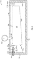
- the apparatus 100 includes a pair of opposing walls 130 connected by a base 140.
- a pair of chucks 150 is provided in the apparatus 100.
- One of the pair of chucks 150a is secured to one of the pair of opposing walls 130a.
- the other one of the chucks 150b is secured to the other one of the pair of opposing walls 130b.
- a profile gauge 160 which may be calibrated, is supported by the pair of opposing walls 130 and configured to move between the pair of chucks 150.
- a rail 170 which may be precision machined, extends between the pair of opposing walls 130 and supports the profile gauge 160 above the pair of chucks 150.
- the profile gauge 160 includes a probe 180 configured for engaging a leading edge 90a of an airfoil 90 secured in the apparatus 100.
- one of the pair of chucks 150a is configured to move toward the other one of the pair of chucks 150b.
- the other one of the pair of chucks 150b is fixed against the other one of the pair of opposing walls 130b.
- the one of the pair of chucks 150a is connected to the one of the pair of opposing walls 130a by a threaded rod 190.
- the one of the pair of opposing walls 130a includes a slot 200, which may be threaded, to operationally connect with the threaded rod 190.
- the slot 200 may be a threaded nut.
- the one of the pair of opposing walls 130a may include a hole 195 aligned with the slot 200 so that the threaded rod 190 may pass through the one of the pair of opposing walls 130 when retracting and advancing the threaded rod 190.
- a method or process S200 of inspecting the airfoil 90 which may be a vane, with the apparatus 100.
- the process includes step S210 of securing a pair of trunnions 210 on opposing ends 215 of the airfoil 90 to the apparatus 100 such that the leading edge 90a of the airfoil 90 is positioned to be inspected by the apparatus 100.
- the pair of trunnions 210 form the axis of rotation, also referred to as the radial axis, of the airfoil 90.
- One of the pair of trunnions 210a is an inner diameter (ID) trunnion and the other one of the pair of trunnions 210b is an outer diameter (OD) trunnion.
- ID inner diameter
- OD outer diameter
- the pair of trunnions 210 are secured between the pair of chucks 150 of the apparatus 100 by advancing one of the pair of chucks 150a toward the other one of the pair of chucks 150b while the other one of the pair of chucks 150b remains stationary.
- the threaded rod 190 of the one of the pair of chucks 150a is rotated within the slot 200 of the apparatus 100. From this, one of the pair of chucks 150a engages one of the pair of trunnions 210a and the other one of the pair of chucks 150b engages the other one of the trunnions 210b.
- Step S220 includes positioning a probe 180 of the profile gauge 160 against the leading edge 90a of the airfoil 90 secured in the apparatus 100.
- Step S230 includes moving the profile gauge 160 of the apparatus 100 along the leading edge 90a of the airfoil 90 in order to obtain a measured profile of the leading edge 90a.
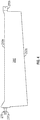
- Step S240 includes comparing the measured profile of the airfoil 90 with another measured profile of a leading edge 250a of another airfoil 260 ( FIG. 4 ), which may be another vane, to determine if the another measured profile is within a predetermined tolerance.
- the airfoil 90 is a vane for the fan inlet case 92
- the another airfoil 260 replacement another vane
- the another measured profile 350 is within the predetermined tolerance. That is, as the airfoil 90 was confirmed to create an acceptable gap relative to an adjacent strut 94 in the fan inlet case 92 at a time of assembly, there is confidence that a gap created between the another airfoil 260 and the adjacent strut 94 will also be acceptable.
- the another measured profile for the another airfoil 260 may be obtained by the same process of obtaining the measured profile disclosed above for the vane being measured.
- the another measured profile may be obtained by securing a pair of trunnions 270, including a first trunnion 270a and a second trunnion 270b of the another airfoil 260 to the apparatus 100 and obtaining the another measured profile with the profile gauge 160.
- the above disclosed embodiments may enable an evaluation of contours of an airfoil 90 such as a vane in a fan inlet case 92 to identify a replacement airfoil with similar contours.
- the replacement airfoil will also fit in the fan inlet case 92. That is, as the vane was confirmed to create an acceptable gap relative to an adjacent strut 94 in the inlet case 92 at a time of assembly, there is confidence that a gap created between the replacement airfoil and the adjacent strut 94 will also be acceptable.
- the disclosed apparatus 100 and process may reduce an inspection time for replacing an airfoil 90.
Landscapes
- Engineering & Computer Science (AREA)
- Physics & Mathematics (AREA)
- General Physics & Mathematics (AREA)
- Mechanical Engineering (AREA)
- General Engineering & Computer Science (AREA)
- Structures Of Non-Positive Displacement Pumps (AREA)
Abstract
Description
- The disclosed embodiments relate to an apparatus and method for inspecting an airfoil profile.
- During periodic maintenance of a gas turbine engine, airfoils such as fan blades and vanes in a fan inlet case may require replacement. Replacement airfoils should fit in within tight aerodynamic envelops in the engine created by spacing requirements between the airfoil and other structures, such as struts.
- According to a first aspect of the disclosure there is provided an apparatus for inspecting an airfoil, the apparatus comprising: a pair of opposing walls connected by a base; a pair of chucks, wherein one of the pair of chucks is secured to one of the pair of opposing walls and the other one of the chucks is secured to the other one of the pair of opposing walls; and a profile gauge supported by the pair of opposing walls and configured to move between the pair of chucks, the profile gauge configured to measure a leading edge profile of the airfoil while moving between the pair of chucks.
- Optionally, the apparatus comprises a rail extending between the pair of opposing walls and supporting the profile gauge above the pair of chucks.
- Optionally, the pair of chucks is configured to move toward the other one of the pair of chucks, and the other one of the pair of chucks is fixed against the other one of the pair of opposing walls.
- Optionally, the one of the pair of chucks is connected to the one of the pair of opposing walls by a threaded rod.
- Optionally, the one of the pair of opposing walls includes a slot to operationally connect with the threaded rod.
- Optionally, one of the pairs of opposing walls has a threaded nut for operationally receiving the threaded rod.
- According to a second aspect of the disclosure there is provided a combination of an airfoil and an apparatus for inspecting the airfoil; the airfoil including a leading edge and trailing edge and a pair of trunnions extending from opposing ends of the airfoil; and the apparatus comprising: a pair of opposing walls connected by a base; a pair of chucks, wherein one of the pair of chucks is secured to one of the pair of opposing walls and the other one of the chucks is secured to the other one of the one of the pair of opposing walls; and a profile gauge supported by the pair of opposing walls and configured to move between the pair of chucks, the profile gauge configured to measure a leading edge profile of the airfoil while moving between the pair of chucks.
- Optionally, the profile gauge includes a probe configured for engaging the leading edge of the airfoil.
- According to a further aspect of the disclosure there is provided a method of inspecting an airfoil, comprising: securing a pair of trunnions of the airfoil to an apparatus for inspecting the airfoil such that a leading edge is positioned to be inspected by the apparatus; and moving a profile gauge of the apparatus along the leading edge when the airfoil is secured in the apparatus in order to obtain a measured profile of the leading edge for the airfoil.
- Optionally, the method includes positioning a probe of the profile gauge against the leading edge when moving the profile gauge along the leading edge.
- Optionally, the method includes securing the pair of trunnions between a pair of chucks of the apparatus so that one of the pair of chucks engages one of the pair of trunnions and the other one of the pair of chucks engages the other one of the trunnions.
- Optionally, the method includes advancing the one of the pair of chucks toward the other one of the pair of chucks while the other one of the pair of chucks remains stationary.
- Optionally, the method includes rotating a threaded rod of the one of the pair of chucks within a slot of the apparatus.
- Optionally, the method includes comparing the measured profile for the airfoil with a measured profile of another airfoil to determine if the measured profile for the another airfoil is within a predetermined tolerance.
- Optionally, the method includes determining to replace the airfoil with the another airfoil upon comparing the measured profile for the airfoil with a measured profile of another airfoil and determining that the measured profile for the another airfoil is within a predetermined tolerance.
- The following descriptions are provided by way of example and should not be considered limiting in any way. With reference to the accompanying drawings, like elements are numbered alike:
-
FIG. 1 is a partial cross sectional view of a gas turbine engine; -
FIG. 2 is an apparatus for inspecting an airfoil with an airfoil secured thereto; -
FIG. 3 is a process for inspecting an airfoil with an apparatus; and -
FIG. 4 is an airfoil having an edge profile that may be measured with an apparatus for inspecting an airfoil. - A detailed description of one or more embodiments of the disclosed apparatus and method are presented herein by way of exemplification and not limitation with reference to the
Figures. 1 . -
FIG. 1 schematically illustrates agas turbine engine 20. Thegas turbine engine 20 is disclosed herein as a two-spool turbofan that generally incorporates afan section 22, acompressor section 24, acombustor section 26 and aturbine section 28. Alternative engines might include an augmentor section (not shown) among other systems or features. Thefan section 22 drives air along a bypass flow path B in a bypass duct, while thecompressor section 24 drives air along a core flow path C for compression and communication into thecombustor section 26 then expansion through theturbine section 28. Although depicted as a two-spool turbofan gas turbine engine in the disclosed non-limiting embodiment, it should be understood that the concepts described herein are not limited to use with two-spool turbofans as the teachings may be applied to other types of turbine engines including three-spool architectures. - The
exemplary engine 20 generally includes alow speed spool 30 and ahigh speed spool 32 mounted for rotation about an engine central longitudinal axis A relative to an enginestatic structure 36 viaseveral bearing systems 38. It should be understood thatvarious bearing systems 38 at various locations may alternatively or additionally be provided, and the location ofbearing systems 38 may be varied as appropriate to the application. - The
low speed spool 30 generally includes aninner shaft 40 that interconnects afan 42, alow pressure compressor 44 and alow pressure turbine 46. Theinner shaft 40 is connected to thefan 42 through a speed change mechanism, which in exemplarygas turbine engine 20 is illustrated as a gearedarchitecture 48 to drive thefan 42 at a lower speed than thelow speed spool 30. Thehigh speed spool 32 includes anouter shaft 50 that interconnects ahigh pressure compressor 52 andhigh pressure turbine 54. Acombustor 56 is arranged inexemplary gas turbine 20 between thehigh pressure compressor 52 and thehigh pressure turbine 54. An enginestatic structure 36 is arranged generally between thehigh pressure turbine 54 and thelow pressure turbine 46. The enginestatic structure 36 further supports bearingsystems 38 in theturbine section 28. Theinner shaft 40 and theouter shaft 50 are concentric and rotate viabearing systems 38 about the engine central longitudinal axis A which is collinear with their longitudinal axes. - The core airflow is compressed by the
low pressure compressor 44 then thehigh pressure compressor 52, mixed and burned with fuel in thecombustor 56, then expanded over thehigh pressure turbine 54 andlow pressure turbine 46. Theturbines low speed spool 30 andhigh speed spool 32 in response to the expansion. It will be appreciated that each of the positions of thefan section 22,compressor section 24,combustor section 26,turbine section 28, and fandrive gear system 48 may be varied. For example,gear system 48 may be located aft ofcombustor section 26 or even aft ofturbine section 28, andfan section 22 may be positioned forward or aft of the location ofgear system 48. - The
engine 20 in one example is a high-bypass geared aircraft engine. In a further example, theengine 20 bypass ratio is greater than about six (6), with an example embodiment being greater than about ten (10), the gearedarchitecture 48 is an epicyclic gear train, such as a planetary gear system or other gear system, with a gear reduction ratio of greater than about 2.3 and thelow pressure turbine 46 has a pressure ratio that is greater than about five. In one disclosed embodiment, theengine 20 bypass ratio is greater than about ten (10:1), the fan diameter is significantly larger than that of thelow pressure compressor 44, and thelow pressure turbine 46 has a pressure ratio that is greater than about five (5:1).Low pressure turbine 46 pressure ratio is pressure measured prior to inlet oflow pressure turbine 46 as related to the pressure at the outlet of thelow pressure turbine 46 prior to an exhaust nozzle. The gearedarchitecture 48 may be an epicycle gear train, such as a planetary gear system or other gear system, with a gear reduction ratio of greater than about 2.3: 1. It should be understood, however, that the above parameters are only exemplary of one embodiment of a geared architecture engine and that the present disclosure is applicable to other gas turbine engines including direct drive turbofans. - A significant amount of thrust is provided by the bypass flow B due to the high bypass ratio. The
fan section 22 of theengine 20 is designed for a particular flight condition--typically cruise at about 0.8 Mach and about 35,000 feet (10,668 meters). The flight condition of 0.8 Mach and 35,000 ft (10,668 meters), with the engine at its best fuel consumption--also known as "bucket cruise Thrust Specific Fuel Consumption ('TSFC')"--is the industry standard parameter of lbm of fuel being burned divided by lbf of thrust the engine produces at that minimum point. "Low fan pressure ratio" is the pressure ratio across the fan blade alone, without a Fan Exit Guide Vane ("FEGV") system. The low fan pressure ratio as disclosed herein according to one non-limiting embodiment is less than about 1.45. "Low corrected fan tip speed" is the actual fan tip speed in ft/sec divided by an industry standard temperature correction of [(Tram °R)/(518.7 °R)]0.5. The "Low corrected fan tip speed" as disclosed herein according to one non-limiting embodiment is less than about 1150 ft/second (350.5 m/sec). - When a current fan inlet variable vane 90 (illustrated schematically in
FIG. 1 ) is replaced during scheduled maintenance, profile features of the current vane should be measured to confirm an exact match with a replacement vane. Such confirmation assures that the vane will fit in a tight aerodynamic envelop within afan inlet case 92, between the vane and anadjacent strut 94. - Turning to
FIG. 2 , disclosed is a fixture orapparatus 100 for inspecting a profile of anairfoil 90, which may be a vane. Theapparatus 100 includes a pair ofopposing walls 130 connected by abase 140. A pair ofchucks 150 is provided in theapparatus 100. One of the pair ofchucks 150a is secured to one of the pair of opposingwalls 130a. The other one of thechucks 150b is secured to the other one of the pair of opposingwalls 130b. Aprofile gauge 160, which may be calibrated, is supported by the pair of opposingwalls 130 and configured to move between the pair ofchucks 150. Arail 170, which may be precision machined, extends between the pair of opposingwalls 130 and supports theprofile gauge 160 above the pair ofchucks 150. Theprofile gauge 160 includes aprobe 180 configured for engaging aleading edge 90a of anairfoil 90 secured in theapparatus 100. - For securing the
airfoil 90, one of the pair ofchucks 150a is configured to move toward the other one of the pair ofchucks 150b. The other one of the pair ofchucks 150b is fixed against the other one of the pair of opposingwalls 130b. The one of the pair ofchucks 150a is connected to the one of the pair of opposingwalls 130a by a threadedrod 190. The one of the pair of opposingwalls 130a includes aslot 200, which may be threaded, to operationally connect with the threadedrod 190. In one embodiment theslot 200 may be a threaded nut. The one of the pair of opposingwalls 130a may include ahole 195 aligned with theslot 200 so that the threadedrod 190 may pass through the one of the pair of opposingwalls 130 when retracting and advancing the threadedrod 190. - Disclosed in
FIG. 3 is a method or process S200 of inspecting theairfoil 90, which may be a vane, with theapparatus 100. The process includes step S210 of securing a pair of trunnions 210 on opposingends 215 of theairfoil 90 to theapparatus 100 such that theleading edge 90a of theairfoil 90 is positioned to be inspected by theapparatus 100. The pair of trunnions 210 form the axis of rotation, also referred to as the radial axis, of theairfoil 90. One of the pair of trunnions 210a is an inner diameter (ID) trunnion and the other one of the pair oftrunnions 210b is an outer diameter (OD) trunnion. - The pair of trunnions 210 are secured between the pair of
chucks 150 of theapparatus 100 by advancing one of the pair ofchucks 150a toward the other one of the pair ofchucks 150b while the other one of the pair ofchucks 150b remains stationary. To advance the one of the pair of chucks 150a, the threadedrod 190 of the one of the pair ofchucks 150a is rotated within theslot 200 of theapparatus 100. From this, one of the pair ofchucks 150a engages one of the pair oftrunnions 210a and the other one of the pair ofchucks 150b engages the other one of thetrunnions 210b. - Step S220 includes positioning a
probe 180 of theprofile gauge 160 against theleading edge 90a of theairfoil 90 secured in theapparatus 100. Step S230 includes moving theprofile gauge 160 of theapparatus 100 along theleading edge 90a of theairfoil 90 in order to obtain a measured profile of theleading edge 90a. Step S240 includes comparing the measured profile of theairfoil 90 with another measured profile of aleading edge 250a of another airfoil 260 (FIG. 4 ), which may be another vane, to determine if the another measured profile is within a predetermined tolerance. For example, if theairfoil 90 is a vane for thefan inlet case 92, as theairfoil 90 being measured fits in theinlet case 92, the another airfoil 260 (replacement another vane) will also fit in theinlet case 92 if the another measured profile 350 is within the predetermined tolerance. That is, as theairfoil 90 was confirmed to create an acceptable gap relative to anadjacent strut 94 in thefan inlet case 92 at a time of assembly, there is confidence that a gap created between the anotherairfoil 260 and theadjacent strut 94 will also be acceptable. - It is to be appreciated that the another measured profile for the another
airfoil 260 may be obtained by the same process of obtaining the measured profile disclosed above for the vane being measured. For example, the another measured profile may be obtained by securing a pair oftrunnions 270, including afirst trunnion 270a and asecond trunnion 270b of the anotherairfoil 260 to theapparatus 100 and obtaining the another measured profile with theprofile gauge 160. - At step S250 a decision is made based on whether the another measured profile is within the predetermined tolerance. If the another measured profile is within the predetermined tolerance, then at step S260 the another airfoil may be selected to replace the
airfoil 90. Otherwise, at step S270 the another airfoil is not selected to replace theairfoil 90. Step S280 ends the process that initiated at step S200. - The above disclosed embodiments may enable an evaluation of contours of an
airfoil 90 such as a vane in afan inlet case 92 to identify a replacement airfoil with similar contours. As theairfoil 90 being measured fits in thefan inlet case 92, the replacement airfoil will also fit in thefan inlet case 92. That is, as the vane was confirmed to create an acceptable gap relative to anadjacent strut 94 in theinlet case 92 at a time of assembly, there is confidence that a gap created between the replacement airfoil and theadjacent strut 94 will also be acceptable. Thus, the disclosedapparatus 100 and process may reduce an inspection time for replacing anairfoil 90. - The term "about" is intended to include the degree of error associated with measurement of the particular quantity based upon the equipment available at the time of filing the application.
- The terminology used herein is for the purpose of describing particular embodiments only and is not intended to be limiting of the present disclosure. As used herein, the singular forms "a", "an" and "the" are intended to include the plural forms as well, unless the context clearly indicates otherwise. It will be further understood that the terms "comprises" and/or "comprising," when used in this specification, specify the presence of stated features, integers, steps, operations, elements, and/or components, but do not preclude the presence or addition of one or more other features, integers, steps, operations, element components, and/or groups thereof.
- While the present disclosure has been described with reference to an exemplary embodiment or embodiments, it will be understood by those skilled in the art that various changes may be made and equivalents may be substituted for elements thereof without departing from the scope of the present disclosure. In addition, many modifications may be made to adapt a particular situation or material to the teachings of the present disclosure without departing from the essential scope thereof. Therefore, it is intended that the present disclosure not be limited to the particular embodiment disclosed as the best mode contemplated for carrying out this present disclosure, but that the present disclosure will include all embodiments falling within the scope of the claims.
Claims (14)
- An apparatus (100) for inspecting an airfoil (90), the apparatus comprising:a pair of opposing walls (130a, 130b) connected by a base (140);a pair of chucks (150a, 150b), wherein one of the pair of chucks is secured to one of the pair of opposing walls and the other one of the chucks is secured to the other one of the pair of opposing walls; anda profile gauge (160) supported by the pair of opposing walls and configured to move between the pair of chucks, the profile gauge configured to measure a leading edge (90a) profile of the airfoil while moving between the pair of chucks.
- The apparatus (100) of claim 1, comprising a rail (170) extending between the pair of opposing walls (130a, 130b) and supporting the profile gauge (160) above the pair of chucks (150a, 150b).
- The apparatus (100) of claims 1 or 2, wherein the one of the pair of chucks (150a) is configured to move toward the other one of the pair of chucks (150b), and the other one of the pair of chucks is fixed against the other one of the pair of opposing walls (150b).
- The apparatus (100) of any of claims 1, 2, or 3, wherein the one of the pair of chucks (150a) is connected to the one of the pair of opposing walls (130a) by a threaded rod (190).
- The apparatus (100) of claim 4, wherein the one of the pair of opposing walls (130a) includes a slot (200) to operationally connect with the threaded rod (190).
- The apparatus (100) of claims 4 or 5, wherein one of the pairs of opposing walls (130a) has a threaded nut for operationally receiving the threaded rod (190).
- In combination an airfoil (90) and an apparatus (100) for inspecting the airfoil;
the airfoil including a leading edge (90a) and trailing edge and a pair of trunnions (210) extending from opposing ends of the airfoil; and
the apparatus comprising the apparatus of any preceding claim. - A method of inspecting an airfoil (90), comprising:securing a pair of trunnions (210a, 210b) of the airfoil to an apparatus (100) for inspecting the airfoil such that a leading edge (90a) is positioned to be inspected by the apparatus; andmoving a profile gauge (160) of the apparatus along the leading edge when the airfoil is secured in the apparatus in order to obtain a measured profile of the leading edge for the airfoil.
- The method of claim 8, including positioning a probe (180) of the profile gauge (160) against the leading edge (90a) when moving the profile gauge along the leading edge.
- The method of claim 8 or 9, including securing the pair of trunnions (210a, 210b) between a pair of chucks (150a, 150b) of the apparatus (100) so that one of the pair of chucks engages one of the pair of trunnions and the other one of the pair of chucks engages the other one of the trunnions.
- The method of claim 10, including advancing the one of the pair of chucks (150a, 150b) toward the other one of the pair of chucks while the other one of the pair of chucks remains stationary.
- The method of claim 11, including rotating a threaded rod (190) of the one of the pair of chucks (150a, 150b) within a slot (200) of the apparatus (100).
- The method of any of claims 8 to 12, including comparing the measured profile for the airfoil (90) with a measured profile of another airfoil to determine if the measured profile for the another airfoil is within a predetermined tolerance.
- The method of claim 13, including determining to replace the airfoil (90) with the another airfoil upon comparing the measured profile for the airfoil with a measured profile of another airfoil and determining that the measured profile for the another airfoil is within a predetermined tolerance.
Applications Claiming Priority (1)
| Application Number | Priority Date | Filing Date | Title |
|---|---|---|---|
| US16/380,492 US11162365B2 (en) | 2019-04-10 | 2019-04-10 | Apparatus and method for inspecting an airfoil profile |
Publications (2)
| Publication Number | Publication Date |
|---|---|
| EP3722739A1 true EP3722739A1 (en) | 2020-10-14 |
| EP3722739B1 EP3722739B1 (en) | 2023-05-10 |
Family
ID=70110196
Family Applications (1)
| Application Number | Title | Priority Date | Filing Date |
|---|---|---|---|
| EP20167289.6A Active EP3722739B1 (en) | 2019-04-10 | 2020-03-31 | Apparatus and method for inspecting an airfoil profile |
Country Status (2)
| Country | Link |
|---|---|
| US (1) | US11162365B2 (en) |
| EP (1) | EP3722739B1 (en) |
Cited By (1)
| Publication number | Priority date | Publication date | Assignee | Title |
|---|---|---|---|---|
| EP4726175A1 (en) * | 2024-10-08 | 2026-04-15 | Pratt & Whitney Canada Corp. | Tool and method for determining impeller leading edge conformity |
Families Citing this family (1)
| Publication number | Priority date | Publication date | Assignee | Title |
|---|---|---|---|---|
| CN112964157B (en) * | 2021-02-26 | 2024-09-06 | 安徽劲旋风航空科技有限公司 | A propeller airfoil rapid detection tool |
Citations (2)
| Publication number | Priority date | Publication date | Assignee | Title |
|---|---|---|---|---|
| GB763793A (en) * | 1955-01-21 | 1956-12-19 | John Oliver Creek And Edward W | Direct reading linear-dimension gauge apparatus |
| CN103753443B (en) * | 2013-12-16 | 2015-06-24 | 中国民航大学 | A turbine blade clamp |
Family Cites Families (17)
| Publication number | Priority date | Publication date | Assignee | Title |
|---|---|---|---|---|
| US1425275A (en) * | 1921-05-12 | 1922-08-08 | Christian P Paulsen | Three-in-one clamp and vise combined |
| US2224728A (en) * | 1938-07-09 | 1940-12-10 | Westinghouse Electric & Mfg Co | Thickness gauge |
| US2453306A (en) * | 1945-05-24 | 1948-11-09 | Avco Mfg Corp | Apparatus for measuring wall thickness of propeller blades |
| GB679724A (en) * | 1949-06-27 | 1900-01-01 | ||
| US2964850A (en) * | 1957-01-31 | 1960-12-20 | Herman Martin Andrew | Universal style gage |
| US3208151A (en) * | 1962-03-27 | 1965-09-28 | Rank Precision Ind Ltd | Testing of surface straightness |
| US3348057A (en) * | 1964-09-17 | 1967-10-17 | Leblond Mach Tool Co R K | Method and apparatus for checking the straightness of machine tool ways and the like |
| IT1120335B (en) * | 1979-04-05 | 1986-03-19 | Finike Italiana Marposs | EQUIPMENT FOR THE CONTROL OF LINEAR DIMENSIONS OF TREES |
| US4454656A (en) | 1982-09-22 | 1984-06-19 | United Technologies Corporation | Minimum chord gauge |
| US4674193A (en) * | 1985-02-27 | 1987-06-23 | Wertepny Alexander W | Bench-center instrument |
| US5301436A (en) * | 1992-09-14 | 1994-04-12 | Johnston Roger B | Cartridge runout fixture |
| US6842995B2 (en) * | 2002-10-09 | 2005-01-18 | General Electric Company | Methods and apparatus for aligning components for inspection |
| US6943570B2 (en) | 2003-09-26 | 2005-09-13 | Honeywell International, Inc. | Device for detecting a crack on a turbine blade of an aircraft engine |
| JP2006003164A (en) * | 2004-06-16 | 2006-01-05 | Fuji Photo Film Co Ltd | Tool for measuring peripheral face shape of roll type article |
| US7762004B2 (en) * | 2007-01-31 | 2010-07-27 | General Electric Company | Inspection tool for measuring bucket Z notch position |
| US7748134B1 (en) * | 2009-03-09 | 2010-07-06 | Yao-Chung Wang | Measuring device for cylinder |
| US9228820B2 (en) * | 2014-02-11 | 2016-01-05 | Chin-Chang Huang | Straightness measuring instrument |
-
2019
- 2019-04-10 US US16/380,492 patent/US11162365B2/en active Active
-
2020
- 2020-03-31 EP EP20167289.6A patent/EP3722739B1/en active Active
Patent Citations (2)
| Publication number | Priority date | Publication date | Assignee | Title |
|---|---|---|---|---|
| GB763793A (en) * | 1955-01-21 | 1956-12-19 | John Oliver Creek And Edward W | Direct reading linear-dimension gauge apparatus |
| CN103753443B (en) * | 2013-12-16 | 2015-06-24 | 中国民航大学 | A turbine blade clamp |
Non-Patent Citations (1)
| Title |
|---|
| WENYAN TANG ET AL: "A new system for automatic measurement of the three-dimensional form of turbine blades", MEASUREMENT SCIENCE AND TECHNOLOGY, IOP, BRISTOL, GB, vol. 5, no. 9, 1 September 1994 (1994-09-01), pages 1042 - 1047, XP020065764, ISSN: 0957-0233, DOI: 10.1088/0957-0233/5/9/002 * |
Cited By (1)
| Publication number | Priority date | Publication date | Assignee | Title |
|---|---|---|---|---|
| EP4726175A1 (en) * | 2024-10-08 | 2026-04-15 | Pratt & Whitney Canada Corp. | Tool and method for determining impeller leading edge conformity |
Also Published As
| Publication number | Publication date |
|---|---|
| US20200325778A1 (en) | 2020-10-15 |
| US11162365B2 (en) | 2021-11-02 |
| EP3722739B1 (en) | 2023-05-10 |
Similar Documents
| Publication | Publication Date | Title |
|---|---|---|
| US11840930B2 (en) | Component with feather seal slots for a gas turbine engine | |
| US11105219B2 (en) | Vane angle system accuracy improvement | |
| US10822983B2 (en) | Hydrostatic seal with abradable teeth for gas turbine engine | |
| US11015715B2 (en) | Ramped spacer ring seal | |
| US10563666B2 (en) | Fan blade with cover and method for cover retention | |
| EP3722739B1 (en) | Apparatus and method for inspecting an airfoil profile | |
| US10774674B2 (en) | Set screw gap control between fixed and variable vanes | |
| US10816507B2 (en) | Apparatus and method and system for inspecting a component of a gas turbine engine | |
| US10480326B2 (en) | Vane for variable area turbine | |
| US11002147B2 (en) | Fixed vane pack retaining ring | |
| US10823415B2 (en) | Deflector for combustor of gas turbine engine | |
| US11473433B2 (en) | Airfoil with trailing edge rounding | |
| US10724535B2 (en) | Fan assembly of a gas turbine engine with a tip shroud | |
| EP3859140A1 (en) | Nozzle-to-engine mount reinforcement through which mounting fasteners are visible | |
| US11149653B2 (en) | Bleed valve actuation system having split ring segments and splice bracket | |
| EP3712392A1 (en) | Aerodynamic component for a gas turbine engine | |
| US10648479B2 (en) | Stator segment circumferential gap seal | |
| US11448233B2 (en) | Following blade impact load support | |
| US10358940B2 (en) | Elliptical slot with shielding holes | |
| US20240301805A1 (en) | Bolted joint of gas turbine engine | |
| US10975702B2 (en) | Platform cooling arrangement for a gas turbine engine | |
| US20210317785A1 (en) | Cooling system for a gas turbine engine |
Legal Events
| Date | Code | Title | Description |
|---|---|---|---|
| PUAI | Public reference made under article 153(3) epc to a published international application that has entered the european phase |
Free format text: ORIGINAL CODE: 0009012 |
|
| STAA | Information on the status of an ep patent application or granted ep patent |
Free format text: STATUS: THE APPLICATION HAS BEEN PUBLISHED |
|
| AK | Designated contracting states |
Kind code of ref document: A1 Designated state(s): AL AT BE BG CH CY CZ DE DK EE ES FI FR GB GR HR HU IE IS IT LI LT LU LV MC MK MT NL NO PL PT RO RS SE SI SK SM TR |
|
| AX | Request for extension of the european patent |
Extension state: BA ME |
|
| RAP1 | Party data changed (applicant data changed or rights of an application transferred) |
Owner name: RAYTHEON TECHNOLOGIES CORPORATION |
|
| STAA | Information on the status of an ep patent application or granted ep patent |
Free format text: STATUS: REQUEST FOR EXAMINATION WAS MADE |
|
| 17P | Request for examination filed |
Effective date: 20210414 |
|
| RBV | Designated contracting states (corrected) |
Designated state(s): AL AT BE BG CH CY CZ DE DK EE ES FI FR GB GR HR HU IE IS IT LI LT LU LV MC MK MT NL NO PL PT RO RS SE SI SK SM TR |
|
| GRAP | Despatch of communication of intention to grant a patent |
Free format text: ORIGINAL CODE: EPIDOSNIGR1 |
|
| STAA | Information on the status of an ep patent application or granted ep patent |
Free format text: STATUS: GRANT OF PATENT IS INTENDED |
|
| INTG | Intention to grant announced |
Effective date: 20221222 |
|
| GRAS | Grant fee paid |
Free format text: ORIGINAL CODE: EPIDOSNIGR3 |
|
| GRAA | (expected) grant |
Free format text: ORIGINAL CODE: 0009210 |
|
| STAA | Information on the status of an ep patent application or granted ep patent |
Free format text: STATUS: THE PATENT HAS BEEN GRANTED |
|
| AK | Designated contracting states |
Kind code of ref document: B1 Designated state(s): AL AT BE BG CH CY CZ DE DK EE ES FI FR GB GR HR HU IE IS IT LI LT LU LV MC MK MT NL NO PL PT RO RS SE SI SK SM TR |
|
| REG | Reference to a national code |
Ref country code: GB Ref legal event code: FG4D |
|
| REG | Reference to a national code |
Ref country code: AT Ref legal event code: REF Ref document number: 1567061 Country of ref document: AT Kind code of ref document: T Effective date: 20230515 Ref country code: CH Ref legal event code: EP |
|
| REG | Reference to a national code |
Ref country code: DE Ref legal event code: R096 Ref document number: 602020010600 Country of ref document: DE |
|
| REG | Reference to a national code |
Ref country code: IE Ref legal event code: FG4D |
|
| P01 | Opt-out of the competence of the unified patent court (upc) registered |
Effective date: 20230603 |
|
| REG | Reference to a national code |
Ref country code: LT Ref legal event code: MG9D |
|
| REG | Reference to a national code |
Ref country code: NL Ref legal event code: MP Effective date: 20230510 |
|
| REG | Reference to a national code |
Ref country code: AT Ref legal event code: MK05 Ref document number: 1567061 Country of ref document: AT Kind code of ref document: T Effective date: 20230510 |
|
| PG25 | Lapsed in a contracting state [announced via postgrant information from national office to epo] |
Ref country code: SE Free format text: LAPSE BECAUSE OF FAILURE TO SUBMIT A TRANSLATION OF THE DESCRIPTION OR TO PAY THE FEE WITHIN THE PRESCRIBED TIME-LIMIT Effective date: 20230510 Ref country code: PT Free format text: LAPSE BECAUSE OF FAILURE TO SUBMIT A TRANSLATION OF THE DESCRIPTION OR TO PAY THE FEE WITHIN THE PRESCRIBED TIME-LIMIT Effective date: 20230911 Ref country code: NO Free format text: LAPSE BECAUSE OF FAILURE TO SUBMIT A TRANSLATION OF THE DESCRIPTION OR TO PAY THE FEE WITHIN THE PRESCRIBED TIME-LIMIT Effective date: 20230810 Ref country code: NL Free format text: LAPSE BECAUSE OF FAILURE TO SUBMIT A TRANSLATION OF THE DESCRIPTION OR TO PAY THE FEE WITHIN THE PRESCRIBED TIME-LIMIT Effective date: 20230510 Ref country code: ES Free format text: LAPSE BECAUSE OF FAILURE TO SUBMIT A TRANSLATION OF THE DESCRIPTION OR TO PAY THE FEE WITHIN THE PRESCRIBED TIME-LIMIT Effective date: 20230510 Ref country code: AT Free format text: LAPSE BECAUSE OF FAILURE TO SUBMIT A TRANSLATION OF THE DESCRIPTION OR TO PAY THE FEE WITHIN THE PRESCRIBED TIME-LIMIT Effective date: 20230510 |
|
| RAP4 | Party data changed (patent owner data changed or rights of a patent transferred) |
Owner name: RTX CORPORATION |
|
| PG25 | Lapsed in a contracting state [announced via postgrant information from national office to epo] |
Ref country code: RS Free format text: LAPSE BECAUSE OF FAILURE TO SUBMIT A TRANSLATION OF THE DESCRIPTION OR TO PAY THE FEE WITHIN THE PRESCRIBED TIME-LIMIT Effective date: 20230510 Ref country code: PL Free format text: LAPSE BECAUSE OF FAILURE TO SUBMIT A TRANSLATION OF THE DESCRIPTION OR TO PAY THE FEE WITHIN THE PRESCRIBED TIME-LIMIT Effective date: 20230510 Ref country code: LV Free format text: LAPSE BECAUSE OF FAILURE TO SUBMIT A TRANSLATION OF THE DESCRIPTION OR TO PAY THE FEE WITHIN THE PRESCRIBED TIME-LIMIT Effective date: 20230510 Ref country code: LT Free format text: LAPSE BECAUSE OF FAILURE TO SUBMIT A TRANSLATION OF THE DESCRIPTION OR TO PAY THE FEE WITHIN THE PRESCRIBED TIME-LIMIT Effective date: 20230510 Ref country code: IS Free format text: LAPSE BECAUSE OF FAILURE TO SUBMIT A TRANSLATION OF THE DESCRIPTION OR TO PAY THE FEE WITHIN THE PRESCRIBED TIME-LIMIT Effective date: 20230910 Ref country code: HR Free format text: LAPSE BECAUSE OF FAILURE TO SUBMIT A TRANSLATION OF THE DESCRIPTION OR TO PAY THE FEE WITHIN THE PRESCRIBED TIME-LIMIT Effective date: 20230510 Ref country code: GR Free format text: LAPSE BECAUSE OF FAILURE TO SUBMIT A TRANSLATION OF THE DESCRIPTION OR TO PAY THE FEE WITHIN THE PRESCRIBED TIME-LIMIT Effective date: 20230811 |
|
| PG25 | Lapsed in a contracting state [announced via postgrant information from national office to epo] |
Ref country code: FI Free format text: LAPSE BECAUSE OF FAILURE TO SUBMIT A TRANSLATION OF THE DESCRIPTION OR TO PAY THE FEE WITHIN THE PRESCRIBED TIME-LIMIT Effective date: 20230510 |
|
| PG25 | Lapsed in a contracting state [announced via postgrant information from national office to epo] |
Ref country code: SK Free format text: LAPSE BECAUSE OF FAILURE TO SUBMIT A TRANSLATION OF THE DESCRIPTION OR TO PAY THE FEE WITHIN THE PRESCRIBED TIME-LIMIT Effective date: 20230510 |
|
| PG25 | Lapsed in a contracting state [announced via postgrant information from national office to epo] |
Ref country code: SM Free format text: LAPSE BECAUSE OF FAILURE TO SUBMIT A TRANSLATION OF THE DESCRIPTION OR TO PAY THE FEE WITHIN THE PRESCRIBED TIME-LIMIT Effective date: 20230510 Ref country code: SK Free format text: LAPSE BECAUSE OF FAILURE TO SUBMIT A TRANSLATION OF THE DESCRIPTION OR TO PAY THE FEE WITHIN THE PRESCRIBED TIME-LIMIT Effective date: 20230510 Ref country code: RO Free format text: LAPSE BECAUSE OF FAILURE TO SUBMIT A TRANSLATION OF THE DESCRIPTION OR TO PAY THE FEE WITHIN THE PRESCRIBED TIME-LIMIT Effective date: 20230510 Ref country code: EE Free format text: LAPSE BECAUSE OF FAILURE TO SUBMIT A TRANSLATION OF THE DESCRIPTION OR TO PAY THE FEE WITHIN THE PRESCRIBED TIME-LIMIT Effective date: 20230510 Ref country code: DK Free format text: LAPSE BECAUSE OF FAILURE TO SUBMIT A TRANSLATION OF THE DESCRIPTION OR TO PAY THE FEE WITHIN THE PRESCRIBED TIME-LIMIT Effective date: 20230510 Ref country code: CZ Free format text: LAPSE BECAUSE OF FAILURE TO SUBMIT A TRANSLATION OF THE DESCRIPTION OR TO PAY THE FEE WITHIN THE PRESCRIBED TIME-LIMIT Effective date: 20230510 |
|
| REG | Reference to a national code |
Ref country code: DE Ref legal event code: R097 Ref document number: 602020010600 Country of ref document: DE |
|
| PLBE | No opposition filed within time limit |
Free format text: ORIGINAL CODE: 0009261 |
|
| STAA | Information on the status of an ep patent application or granted ep patent |
Free format text: STATUS: NO OPPOSITION FILED WITHIN TIME LIMIT |
|
| 26N | No opposition filed |
Effective date: 20240213 |
|
| PG25 | Lapsed in a contracting state [announced via postgrant information from national office to epo] |
Ref country code: SI Free format text: LAPSE BECAUSE OF FAILURE TO SUBMIT A TRANSLATION OF THE DESCRIPTION OR TO PAY THE FEE WITHIN THE PRESCRIBED TIME-LIMIT Effective date: 20230510 |
|
| PG25 | Lapsed in a contracting state [announced via postgrant information from national office to epo] |
Ref country code: SI Free format text: LAPSE BECAUSE OF FAILURE TO SUBMIT A TRANSLATION OF THE DESCRIPTION OR TO PAY THE FEE WITHIN THE PRESCRIBED TIME-LIMIT Effective date: 20230510 Ref country code: IT Free format text: LAPSE BECAUSE OF FAILURE TO SUBMIT A TRANSLATION OF THE DESCRIPTION OR TO PAY THE FEE WITHIN THE PRESCRIBED TIME-LIMIT Effective date: 20230510 |
|
| REG | Reference to a national code |
Ref country code: CH Ref legal event code: PL |
|
| PG25 | Lapsed in a contracting state [announced via postgrant information from national office to epo] |
Ref country code: BG Free format text: LAPSE BECAUSE OF FAILURE TO SUBMIT A TRANSLATION OF THE DESCRIPTION OR TO PAY THE FEE WITHIN THE PRESCRIBED TIME-LIMIT Effective date: 20230510 |
|
| PG25 | Lapsed in a contracting state [announced via postgrant information from national office to epo] |
Ref country code: LU Free format text: LAPSE BECAUSE OF NON-PAYMENT OF DUE FEES Effective date: 20240331 |
|
| PG25 | Lapsed in a contracting state [announced via postgrant information from national office to epo] |
Ref country code: MC Free format text: LAPSE BECAUSE OF FAILURE TO SUBMIT A TRANSLATION OF THE DESCRIPTION OR TO PAY THE FEE WITHIN THE PRESCRIBED TIME-LIMIT Effective date: 20230510 |
|
| PG25 | Lapsed in a contracting state [announced via postgrant information from national office to epo] |
Ref country code: MC Free format text: LAPSE BECAUSE OF FAILURE TO SUBMIT A TRANSLATION OF THE DESCRIPTION OR TO PAY THE FEE WITHIN THE PRESCRIBED TIME-LIMIT Effective date: 20230510 Ref country code: LU Free format text: LAPSE BECAUSE OF NON-PAYMENT OF DUE FEES Effective date: 20240331 Ref country code: BG Free format text: LAPSE BECAUSE OF FAILURE TO SUBMIT A TRANSLATION OF THE DESCRIPTION OR TO PAY THE FEE WITHIN THE PRESCRIBED TIME-LIMIT Effective date: 20230510 |
|
| REG | Reference to a national code |
Ref country code: BE Ref legal event code: MM Effective date: 20240331 |
|
| PG25 | Lapsed in a contracting state [announced via postgrant information from national office to epo] |
Ref country code: BE Free format text: LAPSE BECAUSE OF NON-PAYMENT OF DUE FEES Effective date: 20240331 |
|
| PG25 | Lapsed in a contracting state [announced via postgrant information from national office to epo] |
Ref country code: IE Free format text: LAPSE BECAUSE OF NON-PAYMENT OF DUE FEES Effective date: 20240331 |
|
| PG25 | Lapsed in a contracting state [announced via postgrant information from national office to epo] |
Ref country code: IE Free format text: LAPSE BECAUSE OF NON-PAYMENT OF DUE FEES Effective date: 20240331 Ref country code: BE Free format text: LAPSE BECAUSE OF NON-PAYMENT OF DUE FEES Effective date: 20240331 Ref country code: CH Free format text: LAPSE BECAUSE OF NON-PAYMENT OF DUE FEES Effective date: 20240331 |
|
| PG25 | Lapsed in a contracting state [announced via postgrant information from national office to epo] |
Ref country code: CY Free format text: LAPSE BECAUSE OF FAILURE TO SUBMIT A TRANSLATION OF THE DESCRIPTION OR TO PAY THE FEE WITHIN THE PRESCRIBED TIME-LIMIT; INVALID AB INITIO Effective date: 20200331 |
|
| PG25 | Lapsed in a contracting state [announced via postgrant information from national office to epo] |
Ref country code: HU Free format text: LAPSE BECAUSE OF FAILURE TO SUBMIT A TRANSLATION OF THE DESCRIPTION OR TO PAY THE FEE WITHIN THE PRESCRIBED TIME-LIMIT; INVALID AB INITIO Effective date: 20200331 |
|
| REG | Reference to a national code |
Ref country code: DE Ref legal event code: R081 Ref document number: 602020010600 Country of ref document: DE Owner name: RTX CORPORATION (N.D.GES.D. STAATES DELAWARE),, US Free format text: FORMER OWNER: RAYTHEON TECHNOLOGIES CORPORATION, FARMINGTON, CT, US |
|
| PG25 | Lapsed in a contracting state [announced via postgrant information from national office to epo] |
Ref country code: TR Free format text: LAPSE BECAUSE OF FAILURE TO SUBMIT A TRANSLATION OF THE DESCRIPTION OR TO PAY THE FEE WITHIN THE PRESCRIBED TIME-LIMIT Effective date: 20230510 |
|
| PGFP | Annual fee paid to national office [announced via postgrant information from national office to epo] |
Ref country code: GB Payment date: 20260219 Year of fee payment: 7 |
|
| PGFP | Annual fee paid to national office [announced via postgrant information from national office to epo] |
Ref country code: DE Payment date: 20260219 Year of fee payment: 7 |
|
| PGFP | Annual fee paid to national office [announced via postgrant information from national office to epo] |
Ref country code: FR Payment date: 20260220 Year of fee payment: 7 |