EP3722680B1 - Method for carrying out a hydraulic adjustment of a heating system for a building and heating system designed for this purpose - Google Patents
Method for carrying out a hydraulic adjustment of a heating system for a building and heating system designed for this purpose Download PDFInfo
- Publication number
- EP3722680B1 EP3722680B1 EP20168920.5A EP20168920A EP3722680B1 EP 3722680 B1 EP3722680 B1 EP 3722680B1 EP 20168920 A EP20168920 A EP 20168920A EP 3722680 B1 EP3722680 B1 EP 3722680B1
- Authority
- EP
- European Patent Office
- Prior art keywords
- room
- heat exchangers
- temperature
- time
- heat exchanger
- Prior art date
- Legal status (The legal status is an assumption and is not a legal conclusion. Google has not performed a legal analysis and makes no representation as to the accuracy of the status listed.)
- Active
Links
- 238000010438 heat treatment Methods 0.000 title claims description 85
- 238000000034 method Methods 0.000 title claims description 51
- 238000012937 correction Methods 0.000 claims description 27
- 230000009467 reduction Effects 0.000 claims description 14
- 230000008859 change Effects 0.000 claims description 4
- 238000005496 tempering Methods 0.000 description 8
- 230000009471 action Effects 0.000 description 7
- 238000001816 cooling Methods 0.000 description 7
- 238000010586 diagram Methods 0.000 description 6
- 230000001276 controlling effect Effects 0.000 description 4
- 238000012546 transfer Methods 0.000 description 4
- LYCAIKOWRPUZTN-UHFFFAOYSA-N Ethylene glycol Chemical compound OCCO LYCAIKOWRPUZTN-UHFFFAOYSA-N 0.000 description 2
- 230000004913 activation Effects 0.000 description 2
- 238000004364 calculation method Methods 0.000 description 2
- 238000013440 design planning Methods 0.000 description 2
- 238000005265 energy consumption Methods 0.000 description 2
- 238000009434 installation Methods 0.000 description 2
- 238000013439 planning Methods 0.000 description 2
- 230000008569 process Effects 0.000 description 2
- XLYOFNOQVPJJNP-UHFFFAOYSA-N water Substances O XLYOFNOQVPJJNP-UHFFFAOYSA-N 0.000 description 2
- QVGXLLKOCUKJST-UHFFFAOYSA-N atomic oxygen Chemical compound [O] QVGXLLKOCUKJST-UHFFFAOYSA-N 0.000 description 1
- 230000004888 barrier function Effects 0.000 description 1
- 230000006399 behavior Effects 0.000 description 1
- 229920003020 cross-linked polyethylene Polymers 0.000 description 1
- 239000004703 cross-linked polyethylene Substances 0.000 description 1
- 230000007423 decrease Effects 0.000 description 1
- 230000001419 dependent effect Effects 0.000 description 1
- 238000013461 design Methods 0.000 description 1
- 230000000694 effects Effects 0.000 description 1
- 238000005516 engineering process Methods 0.000 description 1
- 230000002349 favourable effect Effects 0.000 description 1
- 230000006870 function Effects 0.000 description 1
- WGCNASOHLSPBMP-UHFFFAOYSA-N hydroxyacetaldehyde Natural products OCC=O WGCNASOHLSPBMP-UHFFFAOYSA-N 0.000 description 1
- 230000006872 improvement Effects 0.000 description 1
- 230000010354 integration Effects 0.000 description 1
- 239000000203 mixture Substances 0.000 description 1
- 238000005457 optimization Methods 0.000 description 1
- 238000013021 overheating Methods 0.000 description 1
- 229910052760 oxygen Inorganic materials 0.000 description 1
- 239000001301 oxygen Substances 0.000 description 1
- 229920003023 plastic Polymers 0.000 description 1
- 239000004033 plastic Substances 0.000 description 1
- 230000005855 radiation Effects 0.000 description 1
- 230000001105 regulatory effect Effects 0.000 description 1
- 230000006641 stabilisation Effects 0.000 description 1
- 238000011105 stabilization Methods 0.000 description 1
- 230000007704 transition Effects 0.000 description 1
- 238000010792 warming Methods 0.000 description 1
Images


Classifications
-
- F—MECHANICAL ENGINEERING; LIGHTING; HEATING; WEAPONS; BLASTING
- F24—HEATING; RANGES; VENTILATING
- F24F—AIR-CONDITIONING; AIR-HUMIDIFICATION; VENTILATION; USE OF AIR CURRENTS FOR SCREENING
- F24F11/00—Control or safety arrangements
- F24F11/88—Electrical aspects, e.g. circuits
-
- F—MECHANICAL ENGINEERING; LIGHTING; HEATING; WEAPONS; BLASTING
- F24—HEATING; RANGES; VENTILATING
- F24D—DOMESTIC- OR SPACE-HEATING SYSTEMS, e.g. CENTRAL HEATING SYSTEMS; DOMESTIC HOT-WATER SUPPLY SYSTEMS; ELEMENTS OR COMPONENTS THEREFOR
- F24D3/00—Hot-water central heating systems
- F24D3/02—Hot-water central heating systems with forced circulation, e.g. by pumps
-
- G—PHYSICS
- G05—CONTROLLING; REGULATING
- G05D—SYSTEMS FOR CONTROLLING OR REGULATING NON-ELECTRIC VARIABLES
- G05D23/00—Control of temperature
- G05D23/19—Control of temperature characterised by the use of electric means
- G05D23/1927—Control of temperature characterised by the use of electric means using a plurality of sensors
- G05D23/193—Control of temperature characterised by the use of electric means using a plurality of sensors sensing the temperaure in different places in thermal relationship with one or more spaces
- G05D23/1932—Control of temperature characterised by the use of electric means using a plurality of sensors sensing the temperaure in different places in thermal relationship with one or more spaces to control the temperature of a plurality of spaces
- G05D23/1934—Control of temperature characterised by the use of electric means using a plurality of sensors sensing the temperaure in different places in thermal relationship with one or more spaces to control the temperature of a plurality of spaces each space being provided with one sensor acting on one or more control means
-
- Y—GENERAL TAGGING OF NEW TECHNOLOGICAL DEVELOPMENTS; GENERAL TAGGING OF CROSS-SECTIONAL TECHNOLOGIES SPANNING OVER SEVERAL SECTIONS OF THE IPC; TECHNICAL SUBJECTS COVERED BY FORMER USPC CROSS-REFERENCE ART COLLECTIONS [XRACs] AND DIGESTS
- Y02—TECHNOLOGIES OR APPLICATIONS FOR MITIGATION OR ADAPTATION AGAINST CLIMATE CHANGE
- Y02B—CLIMATE CHANGE MITIGATION TECHNOLOGIES RELATED TO BUILDINGS, e.g. HOUSING, HOUSE APPLIANCES OR RELATED END-USER APPLICATIONS
- Y02B30/00—Energy efficient heating, ventilation or air conditioning [HVAC]
- Y02B30/70—Efficient control or regulation technologies, e.g. for control of refrigerant flow, motor or heating
Definitions
- the invention relates to a method for performing a hydraulic balancing of a heating system for a building, which has a temperature control element that heats a temperature control medium, a circulating pump, a plurality of heat exchangers connected to the temperature control element and the circulating pump, each heat exchanger being assigned to a room in the building and each heat exchanger a valve that regulates the flow of the tempering medium through the heat exchanger is associated with an actuator associated with this valve, and at least one control unit that controls the actuators of the valves. Furthermore, the present invention relates to a heating system, the control unit of which is designed to provide the operations for carrying out such a method.
- the tempering medium has a temperature that is adapted to the requirement.
- the heat exchangers installed in the rooms, in the case of underfloor heating these are screed surfaces in which the heating circuits through which the temperature control medium flows have different hydraulic properties due to their different dimensions and the resulting different pipe lengths. If several of these heat exchangers are operated simultaneously in a heating system of a building, the temperature control medium may not be distributed to the various heat exchangers as required, and as a result the energy output to the rooms to be supplied may not be adapted to the requirements and, as a consequence, the energy output may not be sufficient warming or overheating of the rooms. In order to avoid these negative effects on comfort and energy consumption, measures are required to create hydraulic conditions in the system that are adapted to the actual requirements. This is called hydronic balancing of the heating system.
- This hydraulic adjustment in surface heating systems is a work step that is part of the professional commissioning of the heating installation or heating system.
- the hydraulic balance is intended to ensure that the heat exchangers are supplied with the amounts of temperature control medium or heat transfer medium determined in the design planning. This creates the prerequisite for the downstream room temperature control to work optimally.
- the hydraulic balance is usually carried out by throttling the heating circuits supplying the heat exchangers when the heating system is commissioned, based on the setting values determined during the design planning.
- the disadvantage here is that when planning the design, wishes of the user of the system that deviate from the usual default values or changes made by the user to the floor coverings that affect the heat transfer between the heat exchanger and the room are not taken into account.
- Measures were developed to solve this problem, through which the work step of manually carried out hydraulic balancing through an intervention of the control system or the control unit, which controls the corresponding drives, which in turn actuate valves on the heating circuit distributor and thus the flow of the heating medium through the heat exchanger release or block, to replace.
- Exemplary methods for carrying out a hydronic balancing are in the EP 1 606 556 A1 , the DE 10 2006 060 324 A1 , the DE 10 2015 121 418 B3 and the DE 10 2011 018 698 A1 described.
- EP 3 009 751 B1 a procedure in which, during a start-up phase of the system, the opening times of the valves in the individual rooms are compared.
- valves in the heating system which are opened and closed by means of motor-driven actuators.
- motor-driven actuators can be brought into a defined position via position pulses or via a constant signal, so that a defined degree of opening of the valves can be set.
- a valve driven by such a motor-driven actuator can be brought to any intermediate position between the "closed” and “fully open” end positions.
- thermoelectric two-point drives which are usually used in a control system for controlling the room temperature of rooms that are heated by a surface heating system.
- thermoelectric two-point drives can assume two end positions in which the valve that can be actuated by the respective drive is open or closed. The transition between the two end positions usually takes place in a period of three to five minutes. During this time, the valve moves between the "closed” and “open” end position. The resulting flow of the heating medium through the heat exchanger varies in this period of time between the value "zero" and a maximum value determined by the currently prevailing hydraulic conditions.
- the present invention comes in, which is based on the object of providing a method for carrying out a hydraulic balancing of a heating system for a building and a heating system whose control unit is designed to provide the operations for carrying out such a method overcome at least one disadvantage of the prior art.
- the method according to the invention should also be carried out with a heating system that uses thermoelectric two-point drives to actuate the valves of the respective heat exchanger.
- the method according to the invention comprises the following steps: First, during a learning phase, it is determined for each room in the building whether the heating of the room is sufficient or whether there is an oversupply or undersupply in the respective room. A correction value for controlling the room temperature is derived from the result.
- the term "learning phase” as used herein denotes a period of the first heating operation of a heating system after the installation of the control unit or after the start of a new heating season.
- the learning phase lasts at least one week and preferably at least two weeks.
- the learning phase should be completed after four weeks at the latest, preferably after three weeks at the latest.
- a plausibility check can then be carried out in an optional intermediate step: For this purpose, the correction values determined for the respective room are compared and, based on the correction values determined, a decision is made as to whether there is (a) a general oversupply or undersupply in the system, or whether (b) individual rooms have an oversupply - or undersupply. If case (b), i. H. If individual rooms are oversupplied or undersupplied during the heating-up phase, the determined room-specific correction values are converted to a so-called room factor in the next step, which can assume a value between 0% and 100%.
- This space factor is used to control the actuators, which control the flow of temperature control medium for the heat exchangers in the rooms via valves, in such a way that over the period calculated by the control technology for opening the valves, the flow of temperature control medium is dimensioned according to the respective space factor limited to the percentage of the original value given by the space factor.
- the present invention lies in the provision of a heating system for a building, which has a temperature control element that heats a temperature control medium, optionally a circulating pump, a plurality of heat exchangers connected to the temperature control element and, if necessary, the circulating pump, each heat exchanger being assigned to a room in the building and each heat exchanger a valve that regulates the flow of the temperature control medium through the heat exchanger and has an actuator assigned to this valve, and at least one control unit that controls the actuators of the valves, the control unit being designed to provide the operations for carrying out a method according to the invention.
- the time-averaged flow rate in stage (b) is reduced after a setpoint change for the respective room towards a higher room temperature setpoint for this room until the increased room temperature setpoint is reached.
- This measure is used to absorb hydraulic peak loads, i.e. when a large quantity of heat transfer medium has to be fed to several heat exchangers at the same time in order to promptly increase the room temperature of the rooms concerned.
- step (b) it can also be helpful if the time-averaged flow rate is reduced in step (b) by reducing the degree of opening of the valves assigned to the corresponding heat exchangers. This represents the variant of reducing the flow through the valve assigned to the respective actuator, which is preferred for continuous actuators.
- thermoelectric actuators is the preferred variant of reducing the flow through the valve assigned to the respective actuator.
- control unit is designed as a PI controller and the integral component in step (a) is used to determine the correction values for the individual heat exchangers.
- the integral component is a possible correction value that is easy to obtain.
- the time-averaged flow rate in stage (b) is reduced for the respective heat exchanger only if the total opening time within a period of the pulse width modulation accounts for 50% of the total period, preferably 70% of the total period, exceeds and at the same time other heat exchangers have a total opening time within a period of the pulse width modulation of more than 50%.
- This measure also serves to intercept hydraulic peak loads.
- the room-specific correction values of the parameters of the control system determined in stage (a) determine the sequence of the start of the cycle time of the pulse width modulation of the heat exchangers, with the heat exchanger in which the correction value causes the greatest reduction in the amount of energy supplied to the heat exchangers compared to the initial parameters being preferably on end of the sequence. In this way, rooms that tend to be undersupplied can be prioritized.
- stage (a) It can also prove to be helpful if the room-specific correction values of the parameters of the control system determined in stage (a) are only used for the heat exchangers whose temperature gradient during a heating process is above the average value of the gradients of all heat exchangers.
- This measure represents a preferred, optional intermediate step between stage (a) and stage (b) of the method according to the invention. This can effectively prevent rooms that are already sufficiently supplied with heat transfer medium from being supplied with an even larger amount of temperature control medium. This serves the comfort generated by the heating system according to the invention and reduces its energy consumption.
- step (a) room-specific correction values for the preset parameters of the control unit are determined during a learning phase of the heating operation in step (a) for the first time during the learning phase. This determination can then preferably be carried out periodically, preferably continuously. This ensures that if changes are made to the control unit, for example changes to the room temperature setpoint for a room, or if there are changes to the external conditions for the heating system, for example laying a floor covering on the screed that affects the heat exchange between the relevant heat exchanger and the room, under which the heating circuit runs, a corresponding adjustment of the hydraulic conditions takes place.
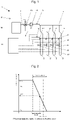
- a heating system 1 in the form of underfloor heating for carrying out a method according to an embodiment of the present invention is shown schematically.
- a temperature control medium eg water or a water/glycol mixture
- the flow heating circuit distributor 4 distributes the temperature control medium to a plurality of heat exchangers 5, 5', 5'', 5′′′, which in the present embodiment are each designed as heating circuits 5, 5', 5", 5′′′ embedded in screed.
- the heating circuits 5, 5 ', 5', 5" lead the tempering medium through the surfaces through which the space in question is to be heated or cooled.
- Two or more heat exchangers 5, 5', 5', 5" can also be assigned to one space. This can be the case, in particular, with relatively large rooms or rooms with a high heating requirement.
- the heat exchangers 5, 5′, 5′′, 5′′′ designed as heating circuits each comprise a valve 6, 6′, 6′′, 6′′′ with an actuator assigned to it, a flow, a consumer (in the case of underfloor heating, for example, the screed of the to be heated or cooled Room, in heating system with radiators a radiator) and a return with a return temperature sensor 7, 7 ', 7', 7 '.
- the heat exchangers 5, 5', 5'', 5′′′ open into a return heating circuit distributor 8. From the return heating circuit distributor 8, the temperature control medium flows through a return line 9 back to a temperature control element 10 for heating or cooling the temperature control medium (e.g. a heat pump or a condensing boiler).
- a temperature control element 10 for heating or cooling the temperature control medium (e.g. a heat pump or a condensing boiler).
- the valves 6, 6′, 6′′, 6′′′ and the actuators assigned to them are arranged in the return of the individual heat exchangers 5, 5′, 5′′, 5′′′ and control the flow of the tempering medium through the individual heat exchangers 5, 5′, 5′′ there. 5′′′.
- a control unit 11 is connected to the individual actuators and controls their operation.
- the valves 6, 6', 6', 6' and the actuators assigned to them can also be assigned to the flow of the individual heat exchangers 5, 5', 5', 5'.
- the heating and/or cooling system 1 can further optionally comprise a circulating pump 16 and/or a connection 12 between the supply line 2 and the return line 9, wherein the connection 12 can be provided with a mixing valve 13.
- the separate circulating pump and/or the connection 12 between the supply line 2 and the return line 9 are not absolutely necessary in every embodiment of the heating and/or cooling system 1 .
- the temperature of the tempering medium in the flow line 2 is measured via the flow temperature sensor 3 and transmitted to the control unit 11 .
- a return temperature sensor 14 assigned to the return line 9 measures the temperature of the temperature control medium in the return line 9 and transmits this to the control unit 11.
- the control unit 11 can control the temperature of the temperature control medium in the flow line 2, for example, by controlling the mixing valve 13 accordingly.
- an outside temperature sensor 15 can determine the outside temperature and in turn pass this on to the control unit 11 .
- the piping of the flow line 2, the heat exchanger 5, 5 ', 5', 5 'and the return line 9 is typically z. B. from plastic pipes made of cross-linked polyethylene, which are provided with an oxygen barrier layer.
- the heating and/or cooling system 1 distributes the amount of heat required in the individual rooms in the case of underfloor heating in that the inflow of tempering medium with a certain temperature into the respective heat exchanger 5, 5' , 5 ⁇ , 5′′′ is regulated/controlled in the floor.
- one heating circuit 5, 5', 5'', 5′′′ is used per room, with the heat supply of a correspondingly large room also requiring two or more heat exchangers 5, 5', 5'', 5′′′.
- the control unit 11 sends corresponding signals to the actuators of the valves 6, 6′, 6′′, 6′′′ to open and close them again for a corresponding period of time.
- the control unit 11 processes the information available on the individual rooms to be controlled, ie the specified desired values and the actual values of the room temperatures reported by room temperature sensors.
- a control algorithm implemented in the control unit 11 generates a control signal therefrom, which is transmitted from the outputs of the control unit 11 via actuators to valves 6, 6′, 6′′, 6′′′ of the heat exchangers 5, 5′, 5′′, 5′′′ becomes.
- a pulse width modulation method known per se is used for this purpose. This represents the basic function of the control unit 11, which can control the heating and/or cooling system 1 independently. In order to ensure that heat is supplied to the individual rooms by the heat exchangers 5, 5′, 5′′, 5′′′ for each load case, these pulse width modulation algorithms of the room temperature control are subjected to a correction.
- the control unit 11 used for controlling the room temperatures is preferably a proportional-integral controller (hereinafter referred to as a PI controller), ie a combination of a proportional controller and an integral controller.
- the control signal of a proportional controller is determined by the position of the variable to be controlled relative to the proportional band, the proportional bandwidth and by the defined direction of action of the controller output signal of the proportional controller.
- the sense of action of the controller output signal describes the direction in which the controller output signal changes when the setpoint remains the same and the actual value changes. If the actual value increases and the controller output signal decreases, this is referred to as the inverse direction of action. If, on the other hand, the controller output signal increases when the actual value increases, this is referred to as direct action.
- the controller output signal is the signal with which the control unit 11 controls the actuators of the respective valves 6, 6′, 6′′, 6′′′ of the heat exchangers 5, 5′, 5′′, 5′′′.
- the control signal of the proportional controller assumes a value between 0 and 100%, with the control signal outside the proportional band, determined by the direction of action and the position in relation to the proportional band, assuming the value 100% or 0%.
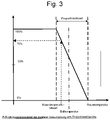
- the control signal changes, again determined by the direction of action and by the direction in which the proportional band is traversed, from the initial value of 100% to the Value 0% or from the value 0% to the value 100%, with a preferably linear dependency between the control signal and the position of the value to be controlled within the proportional band, which in figure 2 and figure 3 is shown.
- the proportional band is in a definable position relative to the setpoint of the variable to be controlled and can be above, below or around the setpoint.
- An essential characteristic of the proportional controller is the immediate, i.e. instantaneous, reaction of the control signal to a change in the setpoint or the actual value.
- the width of the proportional band determines how strongly the proportional controller reacts to the control deviation.
- the control signal of an integral controller is the time integration of the control deviation, i.e. the difference between the current value and the target value, weighted by the reset time. The longer the reset time selected, the slower the control signal changes if the control deviation remains the same.
- An essential characteristic of the integral controller is the non-sudden reaction of the control signal to a change in the setpoint or the actual value.
- the control signal of an integral controller is therefore proportional to a mean value of the control deviation of a previous period of time, which is influenced by the reset time. Since the integral part can grow indefinitely, it is limited to a defined maximum value, for example 50%.
- a combination of a proportional controller and an integral controller, known as a PI controller is usually used to control the room temperature of a surface heating system.
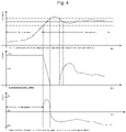
- figure 4 shows the control signals of the two controller types in a typical example of a heating process. The overall signal of the PI controller results from the addition of the two signals, with the resulting signal being limited to the range from 0% to 100%.
- the influence of the integral component is preferably limited to a maximum value. This maximum value depends on the heating system 1 to be controlled by the control unit 11 .
- the constant output signal of the PI controller which is between 0% and 100%, can be converted into a pulse width modulated signal with the two states active and not active. It is based on a cycle time and the active time of the signal is equal in duration to the percentage of the control signal applied to the total cycle time.
- the cycle time is selected depending on the heating system being operated. In the case of an underfloor heating system, a value between 15 and 40 minutes is typically selected for the cycle time.
- the signal is inactive for the remainder of the cycle time. After the cycle time has expired, the next cycle time starts and with it the renewed time of the active state.
- the method of pulse width modulation thus offers the possibility of converting a constant control signal into a control signal which only has the two states "active" and "not active".
- This pulse-width-modulated signal is used to control the already mentioned thermoelectric drives. An example of such a pulse-width-modulated signal over time is shown in the diagram according to figure 5 shown.
- the room-specific correction values can preferably be determined on the basis of the integral part in the learning phase for each room once a day at a specific time, with the integral part being set to zero as long as the actual room temperature value is outside the proportional band.
- This phase is called the warm-up phase.
- the calculation of the integral component only starts when entering the proportional band.
- the phase of operation that then begins is referred to as the stabilization phase.
- the point in time at which the integral part is used to determine the correction value is chosen so that it is in the middle of the presence time specified by the user via a time program. If no time program is used, the time is set to the afternoon, for example at 5 p.m. At the selected point in time, the value of the integral component of the control signal is considered. If the magnitude of the integral signal exceeds 80% of the specified maximum value, the position of the proportional band for this room is adjusted in small steps, e.g. in steps of 5%. The proportional band is shifted in a positive direction for positive integral components and in a negative direction for negative integral components.
- the proportional controller accepts a part of the signal that was generated by the integral controller from the point in time at which the room temperature is in the proportional band, i.e. in the phase referred to as control mode.
- control mode a part of the signal that was generated by the integral controller from the point in time at which the room temperature is in the proportional band.
- the optimization steps are carried out over several days, e.g. over a week.
- the total amount of the proportional band shift must not exceed a maximum value of 50%.
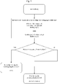
- a flowchart for step (a) according to one embodiment of the method according to the invention is in figure 6 shown.
- the positioning of the proportional band for each room is different from the original value. Rooms that are over-powered will have a negative proportional band shift, rooms that are under-powered will have a positive proportional band shift.
- the proportional band shift determined room by room represents the room-specific correction value for the proportional component of the PI controller and is used as the input variable for the following step.
- a flowchart for step (b) according to an embodiment of the method according to the invention is in figure 8 shown.
- a key figure, referred to below as the room factor is determined for each room for optimized operation, which reflects the extent to which a reduction in the flow through the heat exchanger is to be achieved.
- the room factor determined in this way gives a percentage for each room to which the flow through the heat exchanger or heat exchangers in this room should be limited compared to the uncompensated value.
- the preferred options include taking corrective measures on the hydraulics, i.e. reducing the supply of temperature control medium, in all rooms with the exception of the room with the greatest undersupply or only in a selection of rooms that are considered rooms with a clear detected oversupply can be identified.
- the temperature control medium is to be supplied only when rooms are selected in this way, this can be implemented, for example, as follows: First, the mean value of the proportional band shift PBS_stoff of all rooms is formed. It is then checked whether spaces exist in which the proportional band shift is a value x below the average of the proportional band shift PBS_stoff, a value between 10% and 30% preferably being selected for x. The rooms identified in this way have an oversupply that is above a threshold value, and in a variant of the method described there is the possibility of only considering these rooms for the further steps.
- the heating gradient takes place when the setpoint changes.
- the mean value for all rooms is also formed from these heating gradients. Only those rooms selected in the previous step whose heating gradient has a value that is above the average of all rooms are subsequently taken into account. The procedure used for this is shown in the flowchart figure 8 shown. The calculation of room factors for each room is in figure 9 shown.
- heating gradients are used as an additional criterion for assessing the need to initiate measures to improve the system hydraulics. Corrective measures are to be taken for the rooms selected depending on the selected process variant for further operation, which is optimized with regard to the system hydraulics. If no room was selected in the previous process steps, no measures are taken to optimize the system hydraulics.
- the actuators are controlled in such a way that the valves 6, 6′, 6′′, 6′′′ they actuate during the Activation time have less than the maximum degree of opening.
- the desired degree of opening corresponds to the room factor determined for the room.
- the actuators are controlled during the active time in such a way that they open and close the valve 6, 6′, 6′′, 6′′′ in constant alternation, so that the flow rate considered over the entire period is limited by the space factor becomes.
- one of the methods listed above for reducing the flow through the heating circuits 5, 5′, 5′′, 5′′′ of the oversupplied rooms is only carried out if it is to be expected that with a non-reduced flow through them Heating circuits 5, 5', 5'', 5′′′ the flow through the heating circuits 5, 5', 5'', 5′′′ of the other rooms is reduced
- the following criterion was set up: Should the opening time of the valves 6, 6', 6'', 6′′′ calculated using the pulse width modulation method of at least one room that has been identified as being oversupplied exceed a period of 70% of the pulse period duration and at the same time in at least one of the rooms , which was recognized as not being oversupplied, a calculated opening time of the valves 6, 6′, 6′′, 6′′′ exceeds a period of 50% of the pulse period duration, a reduction in the flow rate of the heating circuits of the oversupplied rooms is applied.
- a further improvement in the hydraulic conditions in a system can be achieved by using the space factors to derive a sequence for opening the valves 6, 6', 6', 6' of the heating circuits 5, 5', 5', 5' of the various derive spaces.
- the actuator of the valve 6, 6′, 6′′, 6′′′ assigned to the room with the highest room factor is activated first when using the method of pulse width modulation according to the invention, after which the room follows after a waiting time of preferably 3 minutes, but at least 1 minute the second highest space factor. These steps are continued up to the room with the lowest space factor.
Description
Die Erfindung bezieht sich auf ein Verfahren zur Durchführung eines hydraulischen Abgleichs eines Heizsystems für ein Gebäude, welches ein ein Temperiermedium erwärmendes Temperierelement, eine Umwälzpumpe, mehrere mit dem Temperierelement und der Umwälzpumpe verbundene Wärmetauscher, wobei jeder Wärmetauscher einem Raum des Gebäudes zugeordnet ist und jedem Wärmetauscher ein den Durchfluss des Temperiermediums durch den Wärmetauscher regelndes Ventil mit einem diesem Ventil zugeordneten Stellantrieb zugeordnet ist, sowie mindestens eine Regeleinheit, die die Stellantriebe der Ventile steuert. Darüber hinaus bezieht sich die vorliegende Erfindung auf ein Heizsystem, dessen Regeleinheit zur Bereitstellung der Operationen zur Durchführung eines derartigen Verfahrens ausgebildet ist.The invention relates to a method for performing a hydraulic balancing of a heating system for a building, which has a temperature control element that heats a temperature control medium, a circulating pump, a plurality of heat exchangers connected to the temperature control element and the circulating pump, each heat exchanger being assigned to a room in the building and each heat exchanger a valve that regulates the flow of the tempering medium through the heat exchanger is associated with an actuator associated with this valve, and at least one control unit that controls the actuators of the valves. Furthermore, the present invention relates to a heating system, the control unit of which is designed to provide the operations for carrying out such a method.
Für den energieeffizienten und den Komfortbedürfnissen der Nutzer gerecht werdenden Betrieb einer wasserbetriebenen Heizungsanlage ist es notwendig, dafür zu sorgen, dass die in den Räumen installierten Wärmetauscher mit einer an den Heizbedarf der Räume angepassten Menge an Temperiermedium durchströmt werden. Dabei weist das Temperiermedium eine an den Bedarf angepasste Temperatur auf.For the energy-efficient operation of a water-powered heating system that meets the comfort needs of the users, it is necessary to ensure that the heat exchangers installed in the rooms are flowed through with an amount of temperature control medium that is adapted to the heating requirements of the rooms. The tempering medium has a temperature that is adapted to the requirement.
Die in den Räumen installierten Wärmetauscher, im Falle einer Fußbodenheizung handelt es sich hier um Estrichflächen, in denen die vom Temperiermedium durchströmten Heizkreise liegen, weisen bedingt durch ihre unterschiedlichen Abmessungen und die damit resultierenden unterschiedlichen Rohrlängen unterschiedliche hydraulische Eigenschaften auf. Beim gleichzeitigen Betrieb mehrerer dieser Wärmetauscher in einem Heizsystem eines Gebäudes kann es dabei zu einer nicht bedarfsgerechten Verteilung des Temperiermediums auf die verschiedenen Wärmetauscher und in Folge davon zu einer nicht an den Bedarf angepassten Energieabgabe an die zu versorgenden Räume und in der Konsequenz zu einer nicht ausreichenden Erwärmung oder zu einer Überhitzung der Räume kommen. Um diese negativen Auswirkungen auf Komfort und Energieverbrauch zu vermeiden, sind Maßnahmen erforderlich, die an den tatsächlichen Bedarf angepasste hydraulische Verhältnisse in der Anlage zu schaffen. Dies wird als hydraulischer Abgleich des Heizsystems bezeichnet.The heat exchangers installed in the rooms, in the case of underfloor heating these are screed surfaces in which the heating circuits through which the temperature control medium flows have different hydraulic properties due to their different dimensions and the resulting different pipe lengths. If several of these heat exchangers are operated simultaneously in a heating system of a building, the temperature control medium may not be distributed to the various heat exchangers as required, and as a result the energy output to the rooms to be supplied may not be adapted to the requirements and, as a consequence, the energy output may not be sufficient warming or overheating of the rooms. In order to avoid these negative effects on comfort and energy consumption, measures are required to create hydraulic conditions in the system that are adapted to the actual requirements. This is called hydronic balancing of the heating system.
Dieser hydraulische Abgleich bei Flächenheizungssystemen ist ein Arbeitsschritt, der zur fachgerechten Inbetriebsetzung der Heizungsanlage bzw. des Heizsystems gehört. Durch den hydraulischen Abgleich soll gewährleistet werden, dass die Wärmetauscher mit den in der Auslegungsplanung ermittelten Mengen an Temperiermedium bzw. Wärmeträgermedium versorgt werden. Damit wird die Voraussetzung dafür geschaffen, dass die nachgeschaltete Raumtemperaturregelung optimal arbeitet. Üblicherweise erfolgt der hydraulische Abgleich durch ein Abdrosseln der die Wärmetauscher versorgenden Heizkreise bei der Inbetriebsetzung der Heizanlage auf Basis der durch die Auslegungsplanung ermittelten Einstellwerte. Nachteilig ist dabei, dass bei der Auslegungsplanung von den üblichen Vorgabewerten abweichende Wünsche des Nutzers der Anlage oder durch den Nutzer vorgenommene Änderungen an den Bodenbelägen, die sich auf den Wärmeübergang zwischen Wärmetauscher und Raum auswirken, nicht berücksichtigt werden.This hydraulic adjustment in surface heating systems is a work step that is part of the professional commissioning of the heating installation or heating system. The hydraulic balance is intended to ensure that the heat exchangers are supplied with the amounts of temperature control medium or heat transfer medium determined in the design planning. This creates the prerequisite for the downstream room temperature control to work optimally. The hydraulic balance is usually carried out by throttling the heating circuits supplying the heat exchangers when the heating system is commissioned, based on the setting values determined during the design planning. The disadvantage here is that when planning the design, wishes of the user of the system that deviate from the usual default values or changes made by the user to the floor coverings that affect the heat transfer between the heat exchanger and the room are not taken into account.
Zur Lösung dieses Problems wurden Maßnahmen entwickelt, durch die der Arbeitsschritt des manuell durchgeführten hydraulischen Abgleichs durch einen Eingriff des Regelungssystems bzw. der Regeleinheit, das bzw. die entsprechende Antriebe ansteuert, die wiederum Ventile am Heizkreisverteiler betätigen und damit den Durchfluss des Heizmediums durch die Wärmetauscher freigeben oder sperren, zu ersetzen. Exemplarische Methoden zur Durchführung eines hydraulischen Abgleichs sind in der
An dieser Stelle setzt die vorliegende Erfindung ein, der die Aufgabe zugrunde liegt, ein Verfahren zur Durchführung eines hydraulischen Abgleichs eines Heizsystems für ein Gebäude sowie ein Heizsystem, dessen Regeleinheit zur Bereitstellung der Operationen zur Durchführung eines derartigen Verfahrens ausgebildet ist, zur Verfügung stellen, die mindestens einen Nachteil des Stands der Technik überwinden. Insbesondere soll das erfindungsgemäße Verfahren auch mit einem Heizsystem durchgeführt werden, das thermoelektrische Zweipunkt-Antriebe zur Betätigung der Ventile der jeweiligen Wärmetauscher verwendet.This is where the present invention comes in, which is based on the object of providing a method for carrying out a hydraulic balancing of a heating system for a building and a heating system whose control unit is designed to provide the operations for carrying out such a method overcome at least one disadvantage of the prior art. In particular, the method according to the invention should also be carried out with a heating system that uses thermoelectric two-point drives to actuate the valves of the respective heat exchanger.
Diese und andere Aufgaben werden durch ein Verfahren mit den Merkmalen des Anspruchs 1 bzw. durch ein Heizsystem mit den Merkmalen des Anspruchs 9 gelöst. Bevorzugte Ausführungsformen des erfindungsgemäßen Verfahrens sind in den abhängigen Ansprüchen beschrieben.This and other objects are achieved by a method having the features of
Gemäß der vorliegenden Erfindung wurde erkannt, dass durch Analyse des Regelverhaltens der Raumtemperaturregelung unter Berücksichtigung der vom Nutzer gewünschten Raumtemperatursollwerte sowie unter Berücksichtigung der gegenüber der ursprünglichen Anlagenplanung veränderten Rahmenbedingungen für jeden der zu versorgende Räume eine raumspezifische Kennzahl ermittelt werden kann, die auf die Ansteuerung der Stellantriebe so angewendet wird, dass eine an den tatsächlichen Bedarf angepasste Versorgung der Räume gewährleistet wird. Dazu umfasst das erfindungsgemäße Verfahren folgende Schritte:
Zunächst wird während einer Lernphase für jeden Raum des Gebäudes ermittelt, ob die Beheizung des Raums ausreichend ist oder ob eine Über- oder Unterversorgung des jeweiligen Raums erfolgt. Aus dem Ergebnis wird ein Korrekturwert für die Regelung der Raumtemperatur abgeleitet. Der Begriff "Lernphase" wie hierin verwendet bezeichnet dabei einen Zeitraum des ersten Heizbetriebs eines Heizsystems nach der Installation der Regeleinheit oder nach Beginn einer neuen Heizperiode. Die Lernphase beträgt dabei mindestens eine Woche und vorzugsweise mindestens zwei Wochen. Die Lernphase sollte nach spätestens vier Wochen, vorzugsweise nach spätestens drei Wochen abgeschlossen sein.According to the present invention, it was recognized that by analyzing the control behavior of the room temperature control, taking into account the room temperature setpoints desired by the user and taking into account the framework conditions that have changed compared to the original system planning, a room-specific key figure can be determined for each of the rooms to be supplied, which refers to the activation of the actuators is applied in such a way that the supply of the rooms is adapted to the actual needs. To this end, the method according to the invention comprises the following steps:
First, during a learning phase, it is determined for each room in the building whether the heating of the room is sufficient or whether there is an oversupply or undersupply in the respective room. A correction value for controlling the room temperature is derived from the result. The term "learning phase" as used herein denotes a period of the first heating operation of a heating system after the installation of the control unit or after the start of a new heating season. The learning phase lasts at least one week and preferably at least two weeks. The learning phase should be completed after four weeks at the latest, preferably after three weeks at the latest.
Danach kann in einem optionalen Zwischenschritt eine Plausibilitätsprüfung erfolgen: Dazu werden die den jeweiligen Raum ermittelten Korrekturwerte verglichen und anhand der ermittelten Korrekturwerte entschieden, ob in der Anlage (a) eine generelle Über- oder Unterversorgung vorliegt, oder ob (b) einzelne Räume eine Über- oder Unterversorgung aufweisen. Wenn Fall (b), d. h. einzelne Räume in Aufheizphasen über- oder unterversorgt sind, werden im nächsten Schritt die ermittelten raumspeifischen Korrekturwerte auf einen sogenannten Raumfaktor umgerechnet, der einen Wert zwischen 0% und 100% annehmen kann. Dieser Raumfaktor wird auf die Ansteuerung der Stellantriebe, die über Ventile den Zustrom an Temperiermedium für die Wärmetauscher der Räume kontrollieren, so angewendet, dass über den durch die Regelungstechnik errechneten Zeitraum für die Öffnung der Ventile sich eine dem jeweiligen Raumfaktor entsprechende Dimensionierung des Zustroms an Temperiermedium ergibt, die auf den durch den Raumfaktor vorgegebenen prozentualen Anteil des ursprünglichen Werts begrenzt ist. Durch diese Reduktion des Zustroms an Temperiermedium von überversorgten Räumen wird durch die dadurch erfolgende Einflussnahme auf die hydraulischen Verhältnisse gleichzeitig der Zustrom an Temperiermedium in die unterversorgten Räume erhöht.A plausibility check can then be carried out in an optional intermediate step: For this purpose, the correction values determined for the respective room are compared and, based on the correction values determined, a decision is made as to whether there is (a) a general oversupply or undersupply in the system, or whether (b) individual rooms have an oversupply - or undersupply. If case (b), i. H. If individual rooms are oversupplied or undersupplied during the heating-up phase, the determined room-specific correction values are converted to a so-called room factor in the next step, which can assume a value between 0% and 100%. This space factor is used to control the actuators, which control the flow of temperature control medium for the heat exchangers in the rooms via valves, in such a way that over the period calculated by the control technology for opening the valves, the flow of temperature control medium is dimensioned according to the respective space factor limited to the percentage of the original value given by the space factor. This reduction in the flow of temperature control medium from oversupplied rooms simultaneously increases the flow of temperature control medium into the undersupplied rooms as a result of the resulting influence on the hydraulic conditions.
Dementsprechend liegt die vorliegende Erfindung in der Bereitstellung eines Verfahrens zur Durchführung eines hydraulischen Abgleichs eines Heizsystems für ein Gebäude, das ein ein Temperiermedium erwärmendes Temperierelement, optional eine Umwälzpumpe, mehrere mit dem Temperierelement und ggf. der Umwälzpumpe verbundene Wärmetauscher r, wobei jeder Wärmetauscher einem Raum des Gebäudes zugeordnet ist und jedem Wärmetauscher ein den Durchfluss des Temperiermediums durch diesen Wärmetauscher regelndes Ventil mit einem diesem Ventil zugeordneten Stellantrieb zugeordnet ist, sowie mindestens eine Regeleinheit, die die Stellantriebe der Ventile durch Pulsweitenmodulation steuert, umfasst, wobei das Verfahren die folgenden Stufen umfasst:
- (a) Ermittlung von raumspezifischen Korrekturwerten für die voreingestellten Parameter der Regeleinheit zumindest während einer Lernphase des Heizbetriebs, die es während der Ausregelphase des Heizsystems, in denen den einzelnen Wärmetauschern Energie zugeführt wird, ermöglichen die Raumtemperatur in dem diesem Wärmetauscher zugeordneten Raum innerhalb eines vorgegebenen Intervalls um einen für den jeweiligen Raum vorgegebenen Raumtemperatursollwert zu halten; und
- (b) Reduzieren des über den Öffnungszeitraum der Ventile zeitlich gemittelten Durchflusses an Temperiermedium derjenigen Wärmetauscher, bei denen die in Stufe (a) ermittelten Korrekturwerte gegenüber den entsprechenden anfänglichen Parametern eine Reduzierung der den Wärmetauschern zugeführten Energiemenge bewirken,
- (a) Determination of room-specific correction values for the preset parameters of the control unit at least during a learning phase of the heating operation, which occurs during the adjustment phase of the heating system in which the individual heat exchangers energy is supplied, allow the room temperature in the room associated with this heat exchanger to be maintained within a predetermined interval around a room temperature setpoint predetermined for the respective room; and
- (b) Reduction of the time-averaged flow rate of tempering medium over the opening period of the valves of those heat exchangers in which the correction values determined in stage (a) cause a reduction in the amount of energy supplied to the heat exchangers compared to the corresponding initial parameters,
Darüber hinaus liegt die vorliegende Erfindung in der Bereitstellung eines Heizsystems für ein Gebäude, das ein ein Temperiermedium erwärmendes Temperierelement, optional eine Umwälzpumpe, mehrere mit dem Temperierelement und ggf. der Umwälzpumpe verbundene Wärmetauscher, wobei jeder Wärmetauscher einem Raum des Gebäudes zugeordnet ist und jedem Wärmetauscher ein den Durchfluss des Temperiermediums durch den Wärmetauscher regelndes Ventil mit einem diesem Ventil zugeordneten Stellantrieb zugeordnet ist, sowie mindestens eine Regeleinheit, die die Stellantriebe der Ventile steuert, umfasst, wobei die Regeleinheit zur Bereitstellung der Operationen zur Durchführung eines erfindungsgemäßen Verfahrens ausgebildet ist.In addition, the present invention lies in the provision of a heating system for a building, which has a temperature control element that heats a temperature control medium, optionally a circulating pump, a plurality of heat exchangers connected to the temperature control element and, if necessary, the circulating pump, each heat exchanger being assigned to a room in the building and each heat exchanger a valve that regulates the flow of the temperature control medium through the heat exchanger and has an actuator assigned to this valve, and at least one control unit that controls the actuators of the valves, the control unit being designed to provide the operations for carrying out a method according to the invention.
Hinsichtlich des erfindungsgemäßen Verfahrens kann es von Vorteil sein, wenn das Reduzieren des zeitlich gemittelten Durchflusses in Stufe (b) nach einem Sollwertwechsel für den jeweiligen Raum hin zu einem höheren Raumtemperatursollwert für diesen Raum bis zum Erreichen des erhöhten Raumtemperatursollwerts erfolgt. Dadurch ist es möglich. Diese Maßnahme dient zum Abfangen hydraulischer Spitzenlasten, also wenn mehreren Wärmetauschern zur selben Zeit eine große Menge an Wärmeträgermedium zugeführt werden muss, um eine zeitnahe Erhöhung der Raumtemperatur der betreffenden Räume zu bewirken.With regard to the method according to the invention, it can be advantageous if the time-averaged flow rate in stage (b) is reduced after a setpoint change for the respective room towards a higher room temperature setpoint for this room until the increased room temperature setpoint is reached. This makes it possible. This measure is used to absorb hydraulic peak loads, i.e. when a large quantity of heat transfer medium has to be fed to several heat exchangers at the same time in order to promptly increase the room temperature of the rooms concerned.
Ebenso kann es hilfreich sein, wenn das Reduzieren des zeitlich gemittelten Durchflusses in Stufe (b) durch Verringern des Öffnungsgrades der den entsprechenden Wärmetauschern zugeordneten Ventile erfolgt. Dies stellt die für stetige Stellantriebe bevorzugte Variante der Verringerung des Durchflusses durch das dem jeweiligen Stellantrieb zugeordnete Ventil dar.It can also be helpful if the time-averaged flow rate is reduced in step (b) by reducing the degree of opening of the valves assigned to the corresponding heat exchangers. This represents the variant of reducing the flow through the valve assigned to the respective actuator, which is preferred for continuous actuators.
Es kann auch günstig sein, wenn das Reduzieren des zeitlich gemittelten Durchflusses in Stufe (b) durch sich abwechselndes Öffnen und Schließen der Ventile erfolgt. Dies stellt die für thermoelektrische Stellantriebe bevorzugte Variante der Verringerung des Durchflusses durch das dem jeweiligen Stellantrieb zugeordnete Ventil dar.It can also be favorable if the time-averaged flow rate is reduced in step (b) by alternately opening and closing the valves. This represents the for thermoelectric actuators is the preferred variant of reducing the flow through the valve assigned to the respective actuator.
Ebenso kann es von Nutzen sein, wenn die Regeleinheit als PI-Regler ausgebildet ist und der Integralanteil in Stufe (a) zur Ermittlung der Korrekturwerte für die einzelnen Wärmetauscher herangezogen wird. Für die bevorzugt verwendeten PI-Regler ist der Integralanteil ein einfach zu erhaltender möglicher Korrekturwert.It can also be useful if the control unit is designed as a PI controller and the integral component in step (a) is used to determine the correction values for the individual heat exchangers. For the PI controller that is preferably used, the integral component is a possible correction value that is easy to obtain.
Es kann auch vorteilhaft sein, wenn das Reduzieren des zeitlich gemittelten Durchflusses in Stufe (b) für den jeweiligen Wärmetauscher nur dann erfolgt, wenn die Gesamtöffnungszeit innerhalb einer Periodendauer der Pulsweitenmodulation einen Anteil von 50% der gesamten Periodendauer, vorzugsweise 70% der gesamten Periodendauer, überschreitet und gleichzeitig andere Wärmetauscher eine Gesamtöffnungszeit innerhalb einer Periodendauer der Pulsweitenmodulation von mehr als 50% aufweisen. Auch diese Maßnahme dient zum Abfangen hydraulischer Spitzenlasten.It can also be advantageous if the time-averaged flow rate in stage (b) is reduced for the respective heat exchanger only if the total opening time within a period of the pulse width modulation accounts for 50% of the total period, preferably 70% of the total period, exceeds and at the same time other heat exchangers have a total opening time within a period of the pulse width modulation of more than 50%. This measure also serves to intercept hydraulic peak loads.
Erfindungsgemäß bestimmen die in Stufe (a) ermittelten raumspezifischen Korrekturwerte der Parameter des Regelungssystems die Reihenfolge des Beginns der Zykluszeit der Pulsweitenmodulation der Wärmetauscher, wobei derjenige Wärmetauscher, bei dem der Korrekturwert gegenüber den anfänglichen Parametern die größte Reduzierung der den Wärmetauschern zugeführten Energiemenge bewirkt, bevorzugt am Ende der Reihenfolge steht. Auf diese Weise kann eine Priorisierung tendenziell unterversorgter Räume erfolgen.According to the invention, the room-specific correction values of the parameters of the control system determined in stage (a) determine the sequence of the start of the cycle time of the pulse width modulation of the heat exchangers, with the heat exchanger in which the correction value causes the greatest reduction in the amount of energy supplied to the heat exchangers compared to the initial parameters being preferably on end of the sequence. In this way, rooms that tend to be undersupplied can be prioritized.
Ebenso kann es sich als hilfreich erweisen, wenn die in Stufe (a) ermittelten raumspezifischen Korrekturwerte der Parameter des Regelungssystems für die in Stufe (b) beschriebene Reduzierung des über den Öffnungszeitraum der Ventile zeitlich gemittelten Durchflusses an Temperiermedium nur für die Wärmetauscher verwendet werden, deren Temperaturgradient bei einem Aufheizvorgang über dem Durchschnittswert der Gradienten aller Wärmetauscher liegt. Diese Maßnahme stellt einen bevorzugten, optionalen Zwischenschritt zwischen Stufe (a) und Stufe (b) des erfindungsgemäßen Verfahrens dar. Dadurch kann wirksam verhindert werden, bereits ausreichend mit Wärmeträgermedium versorgte Räume mit einer noch höheren Menge an Temperiermedium versorgt werden. Dies dient dem durch das erfindungsgemäße Heizsystem generierten Komfort und verringert dessen Energieverbrauch.It can also prove to be helpful if the room-specific correction values of the parameters of the control system determined in stage (a) are only used for the heat exchangers whose temperature gradient during a heating process is above the average value of the gradients of all heat exchangers. This measure represents a preferred, optional intermediate step between stage (a) and stage (b) of the method according to the invention. This can effectively prevent rooms that are already sufficiently supplied with heat transfer medium from being supplied with an even larger amount of temperature control medium. This serves the comfort generated by the heating system according to the invention and reduces its energy consumption.
Es kann auch von Nutzen sein, wenn die Ermittlung von raumspezifischen Korrekturwerten für die voreingestellten Parameter der Regeleinheit während einer Lernphase des Heizbetriebs in Stufe (a) erstmalig während der Lernphase erfolgt. Vorzugsweise kann diese Ermittlung anschließend periodisch, vorzugsweise kontinuierlich durchgeführt werden. Auf diese Weise ist gewährleistet, dass bei Änderungen an der Regeleinheit, beispielsweise Änderungen des Raumtemperatursollwerts für einen Raum, oder bei Änderungen an den äußeren Bedingungen für das Heizsystem, beispielsweise Verlegen eines den Wärmeaustausch zwischen dem entsprechenden Wärmetauscher und dem Raum beeinflussenden Bodenbelags auf dem Estrich, unter dem der Heizkreis verläuft, eine entsprechende Anpassungen der hydraulischen Verhältnisse erfolgt.It can also be useful if room-specific correction values for the preset parameters of the control unit are determined during a learning phase of the heating operation in step (a) for the first time during the learning phase. This determination can then preferably be carried out periodically, preferably continuously. This ensures that if changes are made to the control unit, for example changes to the room temperature setpoint for a room, or if there are changes to the external conditions for the heating system, for example laying a floor covering on the screed that affects the heat exchange between the relevant heat exchanger and the room, under which the heating circuit runs, a corresponding adjustment of the hydraulic conditions takes place.
Im Folgenden werden die einzelnen Stufen des erfindungsgemäßen Verfahrens am Ausführungsbeispiel eines Fußbodenheizungssystems unter Bezugnahme auf die Figuren im Detail erläutert. Dabei versteht es sich, dass die vorliegende Erfindung jedoch nicht darauf beschränkt ist, sondern entsprechend für Heizungssysteme anwendbar ist, die zur Beheizung der Räume andere Arten von Wärmetauscher, wie z. B. Heizkörper oder dergleichen, verwenden. Ebenso kann die vorliegende Erfindung für den Betrieb einer Anlage zum Zweck der Kühlung der Räume eingesetzt werden. Es zeigen:
-
Fig. 1 eine schematische Darstellung eines Heiz- und/oder Kühlsystems zur Durchführung eines Verfahrens gemäß einer Ausführungsform der vorliegenden Erfindung; -
Fig. 2 ein exemplarisches Diagramm eines Ausgangssignals des Proportionalreglers bei negativer Verschiebung des Proportionalbandes; -
Fig. 3 ein exemplarisches Diagramm eines Ausgangssignals des Proportionalreglers bei positiver Verschiebung des Proportionalbandes; -
Fig. 4 ein exemplarisches Diagramm von Regelsignalen eines PI-Regler bei einem Aufheizvorgang; -
Fig. 5 ein exemplarisches Diagramm eines zeitlichen Verlaufs eines pulsweitenmodulierten Signals; -
Fig. 6 ein Flussdiagramm zu Stufe (a) gemäß einer Ausführungsform des erfindungsgemäßen Verfahrens; -
Fig. 7 ein Flussdiagramm zu einem optionalen Zwischenschritt gemäß einer bevorzugten Ausführungsform des erfindungsgemäßen Verfahrens; -
Fig. 8 ein Flussdiagramm zu Stufe (b) gemäß einer Ausführungsform des erfindungsgemäßen Verfahrens; und -
Fig. 9 ein exemplarisches Diagramm zur Ermittlung des Raumfaktors aus der Proportionalbandverschiebung in einer Ausführungsform des erfindungsgemäßen Verfahrens.
-
1 a schematic representation of a heating and/or cooling system for carrying out a method according to an embodiment of the present invention; -
2 an exemplary diagram of an output signal of the proportional controller with a negative shift of the proportional band; -
3 an exemplary diagram of an output signal of the proportional controller with a positive shift of the proportional band; -
4 an exemplary diagram of control signals of a PI controller during a heating process; -
figure 5 an exemplary diagram of a time profile of a pulse width modulated signal; -
6 a flowchart for stage (a) according to an embodiment of the method according to the invention; -
Figure 7 a flowchart for an optional intermediate step according to a preferred embodiment of the method according to the invention; -
8 a flowchart for step (b) according to an embodiment of the method according to the invention; and -
9 an exemplary diagram for determining the space factor from the proportional band shift in an embodiment of the method according to the invention.
In
Die als Heizkreise ausgebildeten Wärmetauscher 5, 5', 5ʺ, 5‴ umfassen jeweils ein Ventil 6, 6', 6ʺ, 6‴ mit einem diesem zugeordneten Stellantrieb, einen Vorlauf, einen Verbraucher (bei Fußbodenheizungen beispielsweise der Estrich des zu beheizenden oder zu kühlenden Raums, bei Heizungssystem mit Heizkörpern ein Heizkörper) und einen Rücklauf mit einem Rücklauf-Temperaturfühler 7, 7', 7ʺ, 7‴. Die Wärmetauscher 5, 5', 5ʺ, 5‴ münden in einem Rücklauf-Heizkreisverteiler 8. Vom Rücklauf-Heizkreisverteiler 8 fließt das Temperiermedium durch eine Rücklaufleitung 9 zurück zu einem Temperierelement 10 zur Erwärmung oder Abkühlung des Temperiermediums (z. B. eine Wärmepumpe oder eine Brennwerttherme).The
Die Ventile 6, 6', 6ʺ, 6‴ und die diesen zugeordneten Stellantriebe sind im Rücklauf der einzelnen Wärmetauscher 5, 5', 5ʺ, 5‴ angeordnet und steuern dort den Durchfluss des Temperiermediums durch die einzelnen Wärmetauscher 5, 5', 5ʺ, 5‴. Eine Regeleinheit 11 ist signalleitend mit den einzelnen Stellantrieben verbunden und steuert ihren Betrieb. Alternativ können die Ventile 6, 6', 6ʺ, 6‴ und die diesen zugeordneten Stellantriebe auch dem Vorlauf der einzelnen Wärmetauscher 5, 5', 5ʺ, 5‴zugeordnet sein. Darüber hinaus kann das Heiz- und/oder Kühlsystem 1 weiter optional eine Umwälzpumpe 16 und/oder eine Verbindung 12 zwischen der Vorlaufleitung 2 und der Rücklaufleitung 9 umfassen, wobei die Verbindung 12 mit einem Mischventil 13 versehen sein kann. Die separate Umwälzpumpe und/oder die Verbindung 12 zwischen der Vorlaufleitung 2 und der Rücklaufleitung 9 sind nicht in jeder Ausführungsform des Heiz- und/oder Kühlsystem 1 zwingend notwendig.The
Über den Vorlauf-Temperaturfühler 3 wird die Temperatur des Temperiermediums in der Vorlaufleitung 2 gemessen und an die Regeleinheit 11 übermittelt. Gleichermaßen misst ein der Rücklaufleitung 9 zugeordneter Rücklauf-Temperaturfühler 14 die Temperatur des Temperiermediums in der Rücklaufleitung 9 und übermittelt diese an die Regeleinheit 11. Die Regeleinheit 11 kann die Temperatur des Temperiermediums in der Vorlaufleitung 2 beispielsweise regeln, indem das Mischventil 13 entsprechend gesteuert wird. Ebenso kann ein Außentemperaturfühler 15 die Außentemperatur ermitteln und diese wiederum an die Regeleinheit 11 weitergeben.The temperature of the tempering medium in the
Die Verrohrung der Vorlaufleitung 2, der Wärmetauscher 5, 5', 5ʺ, 5‴ sowie der Rücklaufleitung 9 besteht typischerweise z. B. aus Kunststoffrohren aus vernetztem Polyethylen, die mit einer Sauerstoffsperrschicht versehen sind.The piping of the
Das Heiz- und/oder Kühlsystem 1 verteilt die in den einzelnen Räumen erforderliche Wärmemenge bei einer Fußbodenheizung dadurch, dass durch die Ventile 6, 6', 6ʺ, 6‴ der Zufluss an Temperiermedium mit einer bestimmten Temperatur in den jeweiligen Wärmetauscher 5, 5', 5ʺ, 5‴ im Boden geregelt/gesteuert wird. In der Regel wird ein Heizkreis 5, 5', 5ʺ, 5‴ pro Raum verwendet, wobei die Wärmeversorgung eines entsprechend großen Raums auch zwei oder mehr Wärmetauscher 5, 5', 5ʺ, 5‴ erfordern kann. Die Regeleinheit 11 sendet entsprechende Signale an die Stellantriebe der Ventile 6, 6', 6ʺ, 6‴ diese für einen entsprechenden Zeitraum zu öffnen und wieder zu schließen. Man spricht von der Öffnungszeit T(open) der Ventile 6, 6', 6ʺ, 6‴.The heating and/or
Die Regeleinheit 11 verarbeitet die zu den einzelnen zu regelnden Räumen vorhandenen Informationen, also die vorgegebenen Sollwerte sowie die von Raumtemperaturfühlern gemeldeten Istwerte der Raumtemperaturen. Ein in der Regeleinheit 11 implementierter Regelungsalgorithmus erzeugt daraus ein Regelsignal, das von den Ausgängen der Regeleinheit 11 über Stellantriebe an Ventile 6, 6', 6ʺ, 6‴ der Wärmetauscher 5, 5', 5ʺ, 5‴ übermittelt wird. Hierzu wird ein an sich bekanntes Pulsweitenmodulationsverfahren eingesetzt. Dies stellt die Grundfunktion der Regeleinheit 11 dar, die an sich selbständig das Heiz- und/oder Kühlsystem 1 regeln kann. Um für eine für jeden Belastungsfall angepasste Wärmeversorgung der einzelnen Räume durch die Wärmetauscher 5, 5', 5ʺ, 5‴ zu gewährleiten, werden diese Pulsweitenmodulationsalgorithmen der Raumtemperaturregelung einer Korrektur unterzogen.The
Die für die Regelung der Raumtemperaturen verwendete Regeleinheit 11 ist vorzugsweise ein Proportional-Integralregler (im Folgenden als PI-Regler bezeichnet), also eine Kombination aus einem Proportionalregler und einem Integralregler. Das Regelsignal eines Proportionalreglers wird durch die Lage der zu regelnden Größe relativ zu dem Proportionalband, der Proportionalbandbreite sowie durch den festgelegten Wirksinn des Reglerausgangssignals des Proportionalreglers bestimmt. Dabei bezeichnet der Wirksinn des Reglerausgangssignals die Richtung, in die sich das Reglerausgangssignal bei gleichbleibendem Sollwert und sich änderndem Istwert ändert. Wenn sich der Istwert erhöht und das Reglerausgangssignal abnimmt, spricht man von inversem Wirksinn. Nimmt das Reglerausgangssignal dagegen zu, wenn der Istwert sich erhöht, spricht man von direktem Wirksinn. Bei einem Regler, der die Beheizung eines Raumes durch das Öffnen eines Ventils regelt, welches den Zufluss eines Heizmediums bestimmt, ist der Wirksinn invers. Das Reglerausgangssignal ist das Signal, mit dem die Regeleinheit 11 die Stellantriebe der jeweiligen Ventile 6, 6', 6ʺ, 6‴ der Wärmetauscher 5, 5', 5ʺ, 5‴ ansteuert.The
Das Regelsignal des Proportionalreglers nimmt einen Wert zwischen 0 und 100% an, wobei das Regelsignal außerhalb des Proportionalbandes, bestimmt durch den Wirksinn sowie der Lage zu dem Proportionalband, den Wert 100% oder 0% annimmt. Bei Eintritt der zu regelnden Größe in den Beginn des Proportionalbands bis zu dem Verlassen des Proportionalbandes am Ende des Proportionalbandes verändert sich das Regelsignal wiederum bestimmt durch den Wirksinn sowie durch die Richtung, in der das Proportionalband durchlaufen wird, von dem Anfangswert 100% bis zu dem Wert 0% bzw. von dem Wert 0% zu dem Wert 100%, wobei eine vorzugsweise lineare Abhängigkeit zwischen dem Regelsignal und der Lages des zu regelnden Werts innerhalb des Proportionalbandes besteht, was in
Eine wesentliche Charakteristik des Proportionalreglers ist die sofortige, also verzögerungsfreie Reaktion des Regelsignals auf eine Veränderung des Sollwertes oder des Istwertes. Die Breite des Proportionalbands bestimmt dabei, wie stark die Reaktion des Proportionalreglers auf die Regelabweichung erfolgt.An essential characteristic of the proportional controller is the immediate, i.e. instantaneous, reaction of the control signal to a change in the setpoint or the actual value. The width of the proportional band determines how strongly the proportional controller reacts to the control deviation.
Das Regelsignal eines Integralreglers ist die zeitliche Integration der Regelabweichung, also der Differenz zwischen aktuellem Wert und angestrebtem Sollwert, gewichtet durch die Nachstellzeit. Je größer die Nachstellzeit gewählt ist, desto langsamer verändert sich das Regelsignal bei einer gleichbleibenden Regelabweichung.The control signal of an integral controller is the time integration of the control deviation, i.e. the difference between the current value and the target value, weighted by the reset time. The longer the reset time selected, the slower the control signal changes if the control deviation remains the same.
Eine wesentliche Charakteristik des Integralreglers ist die nicht sprungartige Reaktion des Regelsignals auf eine Veränderung des Sollwertes oder des Istwertes. Das Regelsignal eines Integralreglers ist damit proportional zu einem durch die Nachstellzeit beeinflussten Mittelwert der Regelabweichung einer zurückliegenden Zeitspanne. Da der Integralanteil unbegrenzt anwachsen kann wird er auf einen definierten Maximalwert, zum Beispiel 50%, begrenzt. Üblicherweise wird für die Raumtemperaturregelung eines Flächenheizunssystems eine Kombination aus einem Proportionalregler und einem Integralregler, genannt PI-Regler, eingesetzt.
Zur Verbesserung des Regelergebnisses wird vorzugsweise der Einfluss des Integralanteils auf einen Maximalwert begrenzt. Dieser Maximalwert ist von dem durch die Regeleinheit 11 zu regelnden Heizsystem 1 abhängig.In order to improve the control result, the influence of the integral component is preferably limited to a maximum value. This maximum value depends on the
Das stetige Ausgangssignal des PI-Reglers, welches zwischen 0% und 100% liegt, kann in ein pulsweitenmoduliertes Signal mit den beiden Zuständen aktiv und nicht aktiv umgesetzt. Dabei wird als Basis eine Zykluszeit festgelegt, und die aktive Zeit des Signals entspricht in ihrer Dauer dem auf die gesamte Zykluszeit angewendeten Prozentsatz des Regelsignals. Die Zykluszeit wird abhängig von dem betriebenen Heizsystem gewählt, bei einem Fußbodenheizungssystem wird für die Zykluszeit typischerweise ein Wert zwischen 15 und 40 Minuten gewählt. Für den restlichen Zeitraum der Zykluszeit ist das Signal inaktiv. Nach Ablauf der Zykluszeit startet die nächste Zykluszeit und damit die erneute Zeit des aktiven Zustands. Die Methode der Pulsweitenmodulation bietet somit die Möglichkeit, ein stetiges Regelsignal in ein Regelsignal umzusetzen, welches nur die beiden Zustände "aktiv" und "nicht aktiv" kennt. Dieses pulsweitenmodulierte Signal wird für die Ansteuerung der bereits erwähnten thermoelektrischen Antriebe verwendet. Ein exemplarischer zeitlicher Verlauf eines solchen pulsweitenmodulierten Signals ist in dem Diagramm gemäß
Das Ermitteln der raumindividuellen Korrekturwerte kann bei Verwendung eines PI-Reglers bevorzugt auf Basis des Integralanteils in der Lernphase für jeden Raum einmal täglich zu einem bestimmten Zeitpunkt, wobei der Integralanteil, solange sich der Istwert der Raumtemperatur außerhalb des Proportionalbandes befindet, zu Null gesetzt wird. Diese Phase wird als Aufheizphase bezeichnet. Erst beim Eintreten in das Proportionalband wird die Berechnung des Integralanteils gestartet. Die dann beginnende Phase des Betriebs wird als Ausregelphase bezeichnet.When using a PI controller, the room-specific correction values can preferably be determined on the basis of the integral part in the learning phase for each room once a day at a specific time, with the integral part being set to zero as long as the actual room temperature value is outside the proportional band. This phase is called the warm-up phase. The calculation of the integral component only starts when entering the proportional band. The phase of operation that then begins is referred to as the stabilization phase.
Der Zeitpunkt für die Verwendung des Integralanteils zur Bestimmung des Korrekturwertes wird so gewählt, dass er in der Mitte der vom Nutzer über ein Zeitprogramm vorgegebenen Anwesenheitszeit liegt. Sollte kein Zeitprogramm verwendet werden, so wird der Zeitpunkt auf den Nachmittag, zum Beispiel auf 17h, gelegt. Zu dem gewählten Zeitpunkt wird der Wert des Integralanteils des Regelsignals betrachtet. Sollte der Betrag des Integralsignals einen Wert von 80% des festgelegten Maximalwerts überschreiten, so wird die Lage des Proportionalbandes für diesen Raum in kleinen Schritten, z.B. in Schritten von 5% angepasst. Für positive Integralanteile erfolgt eine Verschiebung des Proportionalbandes in positiver Richtung, bei negativen Integralanteilen in negativer Richtung.The point in time at which the integral part is used to determine the correction value is chosen so that it is in the middle of the presence time specified by the user via a time program. If no time program is used, the time is set to the afternoon, for example at 5 p.m. At the selected point in time, the value of the integral component of the control signal is considered. If the magnitude of the integral signal exceeds 80% of the specified maximum value, the position of the proportional band for this room is adjusted in small steps, e.g. in steps of 5%. The proportional band is shifted in a positive direction for positive integral components and in a negative direction for negative integral components.
Durch diesen Korrekturschritt übernimmt der Proportionalregler einen Teil des Signals, welches durch den Integralregler ab dem Zeitpunkt, in dem sich die Raumtemperatur im Proportionalband befindet, also in der als Regelbetrieb bezeichneten Phase, erzeugt wurde. Um Störeinflüsse z.B. durch Sonneneinstrahlung oder zeitweilig auftretende innere Lasten zu reduzieren, erfolgen die Optimierungsschritte über mehrere Tage, z.B. über eine Woche hinweg. Der Gesamtbetrag der Proportionalbandverschiebung darf dabei in bevorzugten Ausführungsformen einen Maximalwert von 50% nicht überschreiten.With this correction step, the proportional controller accepts a part of the signal that was generated by the integral controller from the point in time at which the room temperature is in the proportional band, i.e. in the phase referred to as control mode. In order to reduce disruptive influences, e.g. due to solar radiation or intermittent internal loads, the optimization steps are carried out over several days, e.g. over a week. In preferred embodiments, the total amount of the proportional band shift must not exceed a maximum value of 50%.
Ein Flussdiagramm zu Stufe (a) gemäß einer Ausführungsform des erfindungsgemäßen Verfahrens ist in
Die raumweise ermittelte Proportionalbandverschiebung stellt den raumindividuellen Korrekturwert für den Proportionalanteil des PI-Reglers dar und wird als Eingangsgröße für den folgenden Schritt verwendet.The proportional band shift determined room by room represents the room-specific correction value for the proportional component of the PI controller and is used as the input variable for the following step.
Ein Flussdiagramm zu Stufe (b) gemäß einer Ausführungsform des erfindungsgemäßen Verfahrens ist in
Die Ermittlung dieser Kennzahl geschieht nach folgender Formel: ![]()
![]()
Der so ermittelte Raumfaktor gibt damit für jeden Raum eine Prozentzahl an, auf die der Durchfluss durch den oder die Wärmetauscher dieses Raums gegenüber dem unkompensierten Wert begrenzt werden soll.The room factor determined in this way gives a percentage for each room to which the flow through the heat exchanger or heat exchangers in this room should be limited compared to the uncompensated value.
Für das weitere Vorgehen umfassen die bevorzugten Optionen, die korrigierende Maßnahmen an der Hydraulik, also eine Reduzierung der Zufuhr an Temperiermedium, bei allen Räumen mit Ausnahme des Raumes mit der größten Unterversorgung vorzunehmen oder nur bei einer Auswahl von Räumen, die als Räume mit einer deutlich erkannten Überversorgung identifiziert werden.For the further procedure, the preferred options include taking corrective measures on the hydraulics, i.e. reducing the supply of temperature control medium, in all rooms with the exception of the room with the greatest undersupply or only in a selection of rooms that are considered rooms with a clear detected oversupply can be identified.
Soll die Zufuhr an Temperiermedium nur bei einer derartigen Auswahl von Räumen erfolgen, kann dies beispielsweise wie folgt realisiert werden: Zunächst wird der Mittelwert der Proportionalbandverschiebung PBS_mittel aller Räume gebildet. Dann wird überprüft, ob Räume existieren, bei denen die Proportionalbandverschiebung um einen Wert x unter dem Mittelwert der Proportionalbandverschiebung PBS_mittel liegen, wobei für x bevorzugt ein Wert zwischen 10% und 30% gewählt wird. Die so erkannten Räume weisen eine Überversorgung auf, die über einem Schwellenwert liegt und es besteht bei einer Variante des beschriebenen Verfahrens die Möglichkeit, nur diese Räume für die weiteren Schritte zu berücksichtigen.If the temperature control medium is to be supplied only when rooms are selected in this way, this can be implemented, for example, as follows: First, the mean value of the proportional band shift PBS_mittel of all rooms is formed. It is then checked whether spaces exist in which the proportional band shift is a value x below the average of the proportional band shift PBS_mittel, a value between 10% and 30% preferably being selected for x. The rooms identified in this way have an oversupply that is above a threshold value, and in a variant of the method described there is the possibility of only considering these rooms for the further steps.
In dieser Verfahrensvariante besteht zusätzlich die bevorzugte Möglichkeit, ein zweites Kriterium bei der Auswahl der zu berücksichtigenden Räume zusätzlich anzuwenden: Während der Lernphase wird parallel ermittelt, mit welcher Geschwindigkeit der Aufheizvorgang der einzelnen Räume, als Aufheizgradient bezeichnet, bei einem Sollwertwechsel stattfindet. Von diesen Aufheizgradienten wird ebenfalls der Mittelwert über alle Räume gebildet. Nur diejenigen der im vorherigen Schritt ausgewählten Räume, deren Aufheizgradient einen Wert aufweist, der über dem Durchschnitt aller Räume liegt, werden im Weiteren berücksichtigt. Die dazu eingesetzte Vorgehensweise ist in dem Flussdiagramm gemäß
Diese Aufheizgradienten werden als zusätzliches Kriterium für die Beurteilung der Notwendigkeit, Maßnahmen zur Verbesserung der Anlagenhydraulik einzuleiten, verwendet. Für die je nach gewählter Verfahrensvariante ausgewählten Räume sollen für den weiteren, hinsichtlich der Anlagenhydraulik optimierten Betrieb, korrigierende Maßnahmen ergriffen werden. Sollte bei den vorhergehenden Verfahrensschritten kein Raum ausgewählt worden sein, so werden keine Maßnahmen für die Optimierung der Anlagenhydraulik durchgeführt.These heating gradients are used as an additional criterion for assessing the need to initiate measures to improve the system hydraulics. Corrective measures are to be taken for the rooms selected depending on the selected process variant for further operation, which is optimized with regard to the system hydraulics. If no room was selected in the previous process steps, no measures are taken to optimize the system hydraulics.
Diese korrigierenden Maßnahmen, also die Reduzierung des Durchflusses an Temperiermedium, kann auf verschiedene Art erzielt werden: Beispielsweise werden in einer bevorzugten Variante des erfindungsgemäßen Verfahrens die Stellantriebe so angesteuert, dass die von ihnen betätigten Ventile 6, 6', 6ʺ, 6‴ während der Ansteuerungszeit einen geringeren als den maximalen Öffnungsgrad aufweisen. Der gewünschte Öffnungsgrad entspricht dabei dem für den Raum ermittelten Raumfaktor.These corrective measures, i.e. reducing the flow of temperature control medium, can be achieved in various ways: For example, in a preferred variant of the method according to the invention, the actuators are controlled in such a way that the
In einer weiteren Variante des erfindungsgemäßen Verfahrens werden die Stellantriebe während der aktiven Zeit so angesteuert, dass sie in ständigem Wechsel das Ventil 6, 6', 6ʺ, 6‴ öffnen und schließen, so dass der sich über den Gesamtzeitraum betrachtete Durchfluss durch den Raumfaktor begrenzt wird.In a further variant of the method according to the invention, the actuators are controlled during the active time in such a way that they open and close the
In einer weiteren bevorzugten Variante des erfindungsgemäßen Verfahrens wird eine der oben aufgeführten Methoden zur Reduzierung des Durchflusses der Heizkreise 5, 5', 5", 5‴ der überversorgten Räume nur dann durchgeführt, wenn zu erwarten ist, dass bei einem nicht reduzierten Durchfluss durch diese Heizkreise 5, 5', 5ʺ, 5‴ der Durchfluss durch die Heizkreise 5, 5', 5ʺ, 5‴ der anderen Räume reduziert wird. Hierzu wird beispielsweise folgendes Kriterium aufgestellt: Sollte die nach der Methode der Pulsweitenmodulation errechnete Öffnungszeit der Ventile 6, 6', 6ʺ, 6‴ von mindestens einem Raum, der als überversorgt erkannt wurde, eine Zeitdauer von 70% der Pulsperiodendauer überschreiten und gleichzeitig bei mindestens einem der Räume, der als nicht überversorgt erkannt wurde, eine errechnete Öffnungszeit der Ventile 6, 6', 6ʺ, 6‴ eine Zeitdauer von 50% der Pulsperiodendauer überschreiten, so wird eine Reduktion des Durchflusses der Heizkreise der überversorgten Räume angewendet.In a further preferred variant of the method according to the invention, one of the methods listed above for reducing the flow through the
Eine weitere Verbesserung der hydraulischen Verhältnisse in einer Anlage lässt sich erzielen, indem die Raumfaktoren verwendet werden, um daraus eine Reihenfolge für das Öffnen der Ventile 6, 6', 6ʺ, 6‴ der Heizkreise 5, 5', 5ʺ, 5‴ der verschiedenen Räume abzuleiten. Der Stellantrieb des dem Raum zugordneten Ventils 6, 6', 6ʺ, 6‴ mit dem höchsten Raumfaktor wird bei Anwendung des erfindungsgemäßen Verfahrens der Pulsweitenmodulation als erster angesteuert, danach folgt nach einer Wartezeit von vorzugsweise 3 Minuten, mindestens jedoch 1 Minute, der Raum mit dem zweithöchsten Raumfaktor. Diese Schritte werden fortgeführt bis zu dem Raum mit dem niedrigsten Raumfaktor.A further improvement in the hydraulic conditions in a system can be achieved by using the space factors to derive a sequence for opening the
Die vorliegende Erfindung wurde unter Bezugnahme auf die in den Figuren gezeigten Ausführungsformen der vorliegenden Erfindung im Detail beschrieben. Es versteht sich, dass die vorliegende Erfindung nicht auf die gezeigten Ausführungsformen beschränkt ist, sondern sich der Umfang der vorliegenden Erfindung aus den Ansprüchen ergibt.The present invention has been described in detail with reference to the embodiments of the present invention shown in the figures. It should be understood that the present invention is not limited to the embodiments shown, but that the scope of the present invention is defined by the claims.
Claims (9)
- Method for carrying out a hydraulic adjustment of a heating system (1) for a building, comprising a temperature-control element (10) which heats a temperature-control medium, optionally a circulating pump (16), a plurality of heat exchangers (5, 5', 5ʺ, 5‴) connected to the temperature-control element (10) and optionally the circulating pump (16), wherein each heat exchanger (5, 5', 5ʺ, 5‴) is associated with one room of the building, and each heat exchanger (5, 5', 5ʺ, 5‴) is associated with a valve (6, 6', 6ʺ, 6‴) which controls the flow of the temperature-control medium through the heat exchanger (5, 5', 5ʺ, 5‴) and comprises an actuator associated with said valve (6, 6', 6ʺ, 6‴), and at least one control unit (11) which controls the actuators of the valves (6, 6', 6ʺ, 6‴) by means of pulse width modulation, wherein the method comprises the following steps:(a) determining room-specific correction values for the pre-set parameters of the control unit (11), at least during a learning phase of the heating operation, which make it possible, during the correction phase of the heating system (1) in which energy is supplied to the individual heat exchangers (5, 5', 5ʺ, 5‴), to keep the room temperature in the room associated with said heat exchanger (5, 5', 5ʺ, 5‴) within a specified interval around a room temperature target value specified for the relevant room; and(b) reducing the flow of temperature-control medium, time-averaged over the opening time of the valves (6, 6', 6ʺ, 6‴), of those heat exchangers (5, 5', 5ʺ, 5‴) for which the correction values determined in step (a) bring about a reduction in the amount of energy supplied to the heat exchangers (5, 5', 5ʺ, 5‴) compared with the corresponding initial parameters,characterised in that
the room-specific correction values, determined in step (a) for the pre-set parameters of the control unit (11), determine the sequence of the start of the cycle time of the pulse width modulation of the heat exchangers (5, 5', 5ʺ, 5‴), wherein the heat exchanger (5, 5', 5ʺ, 5‴) for which the correction value brings about the greatest reduction in the amount of energy supplied to the heat exchangers (5, 5', 5ʺ, 5‴), compared with the pre-set parameters, is preferably at the end of the sequence. - Method according to claim 1, characterised in that the reduction of the time-averaged flow in step (b) takes place after a target value change for the relevant room, towards a higher room temperature target value for this room, until the increased room temperature target value is reached.
- Method according to either claim 1 or claim 2, characterised in that the reduction of the time-averaged flow in step (b) is carried out by reducing the degree of opening of the valves (6, 6', 6ʺ, 6‴) associated with the corresponding heat exchangers (5, 5', 5ʺ, 5‴).
- Method according to any of claims 1 to 3, characterised in that the reduction of the time-averaged flow in step (b) is carried out by means of alternating opening and closing of the valves (6, 6', 6ʺ, 6‴).
- Method according to any of claims 1 to 4, characterised in that the control unit (11) is designed as a PI controller, and the integral part is consulted in step (a) for determining the correction value for the individual heat exchangers (5, 5', 5ʺ, 5‴).
- Method according to any of claims 1 to 5, characterised in that the reduction of the time-averaged flow in step (b) takes place, for the respective heat exchangers (5, 5', 5ʺ, 5‴), only if the total opening time within one period duration of the pulse width modulation exceeds a fraction of 50% of the entire period duration, preferably 70% of the entire period duration, and at the same time other heat exchangers (5, 5', 5ʺ, 5‴) have a total opening time, within one period duration of the pulse width modulation, of more than 50%.
- Method according to any of claims 1 to 6, characterised in that the correction values, individual to the heat exchangers, determined in step (a), for the parameters of the control system, for the reduction, described in step (b), of the flow of temperature-control medium, time-averaged over the opening time of the valves (6, 6', 6", 6‴), are used only for the heat exchangers (5, 5', 5", 5‴) of which the temperature gradient during a heating process is above the average value of the gradients of all the heat exchangers (5, 5', 5ʺ, 5‴).
- Method according to any of claims 1 to 7, characterised in that the determination of room-specific correction values for the pre-set parameters of the control unit (11), during a learning phase of the heating operation in step (a), takes place for the first time during the learning phase, and is subsequently carried out periodically, preferably continuously.
- Heating system (1) for a building, comprising a temperature-control element (10) which heats a temperature-control medium, optionally a circulating pump (16), a plurality of heat exchangers (5, 5', 5ʺ, 5‴) connected to the temperature-control element (10) and optionally the circulating pump (16), wherein each heat exchanger (5, 5', 5ʺ, 5‴) is associated with one room of the building, and each heat exchanger (5, 5', 5ʺ, 5‴) is associated with a valve (6, 6', 6ʺ, 6‴) which controls the flow of the temperature-control medium through the heat exchanger (5, 5', 5ʺ, 5‴) and comprises an actuator associated with said valve (6, 6', 6ʺ, 6‴), and at least one control unit (11) which controls the actuators of the valves (6, 6', 6ʺ, 6‴),
characterised in that
the control unit (11) is designed to provide the operations for carrying out a method according to any of claims 1 to 8.
Applications Claiming Priority (1)
| Application Number | Priority Date | Filing Date | Title |
|---|---|---|---|
| DE102019109540.9A DE102019109540A1 (en) | 2019-04-11 | 2019-04-11 | Method for performing hydraulic balancing of a heating system for a building and a heating system designed for this purpose |
Publications (2)
| Publication Number | Publication Date |
|---|---|
| EP3722680A1 EP3722680A1 (en) | 2020-10-14 |
| EP3722680B1 true EP3722680B1 (en) | 2022-09-28 |
Family
ID=70277300
Family Applications (1)
| Application Number | Title | Priority Date | Filing Date |
|---|---|---|---|
| EP20168920.5A Active EP3722680B1 (en) | 2019-04-11 | 2020-04-09 | Method for carrying out a hydraulic adjustment of a heating system for a building and heating system designed for this purpose |
Country Status (4)
| Country | Link |
|---|---|
| EP (1) | EP3722680B1 (en) |
| DE (1) | DE102019109540A1 (en) |
| ES (1) | ES2934618T3 (en) |
| HU (1) | HUE061041T2 (en) |
Families Citing this family (4)
| Publication number | Priority date | Publication date | Assignee | Title |
|---|---|---|---|---|
| CN112902291B (en) * | 2021-01-26 | 2022-03-08 | 宁波方太厨具有限公司 | Automatic hydraulic balance adjusting method, device, system, equipment and medium for heating system |
| CN113028494A (en) * | 2021-03-18 | 2021-06-25 | 山东琅卡博能源科技股份有限公司 | Intelligent heat supply dynamic hydraulic balance control method |
| DE102022101313A1 (en) | 2022-01-20 | 2023-07-20 | Vaillant Gmbh | Method for configuring an air conditioning system, computer program, regulation and control device, air conditioning device and use of data |
| DE102022120825A1 (en) * | 2022-08-17 | 2024-02-22 | Blossom-ic-intelligent controls AG | Measuring and analysis system for evaluating the hydraulic balancing of a space heating system |
Family Cites Families (5)
| Publication number | Priority date | Publication date | Assignee | Title |
|---|---|---|---|---|
| DE10312825B4 (en) * | 2003-03-22 | 2006-01-12 | Danfoss A/S | Method for setting a plurality of parallel-connected heat exchangers |
| DE102006060324A1 (en) * | 2006-12-20 | 2008-07-03 | Techem Energy Services Gmbh | Method and system for detecting the hydraulic balancing of a heating system |
| DE102011018698A1 (en) * | 2011-04-26 | 2012-10-31 | Rwe Effizienz Gmbh | Method and system for automatic hydraulic balancing of radiators |
| EP3009751B1 (en) | 2014-10-16 | 2019-01-16 | Danfoss A/S | Heating system and method for hydraulic balancing said heating system |
| DE102015121418B3 (en) * | 2015-12-09 | 2017-03-16 | Oventrop Gmbh & Co. Kg | Method for automatic hydraulic balancing of consumers in a heating and / or cooling plant |
-
2019
- 2019-04-11 DE DE102019109540.9A patent/DE102019109540A1/en active Pending
-
2020
- 2020-04-09 ES ES20168920T patent/ES2934618T3/en active Active
- 2020-04-09 HU HUE20168920A patent/HUE061041T2/en unknown
- 2020-04-09 EP EP20168920.5A patent/EP3722680B1/en active Active
Also Published As
| Publication number | Publication date |
|---|---|
| HUE061041T2 (en) | 2023-05-28 |
| EP3722680A1 (en) | 2020-10-14 |
| DE102019109540A1 (en) | 2020-10-15 |
| ES2934618T3 (en) | 2023-02-23 |
Similar Documents
| Publication | Publication Date | Title |
|---|---|---|
| EP3722680B1 (en) | Method for carrying out a hydraulic adjustment of a heating system for a building and heating system designed for this purpose | |
| EP3593055B1 (en) | Method for operating a heating installation | |
| EP0282886B1 (en) | Process for regulating the start temperature in a heat transfer system | |
| DE102017101047B4 (en) | Method for operating a heating system in a building, and technical building heating system | |
| DE102014103668A1 (en) | Method for operating a heating and / or cooling system | |
| EP1926942A1 (en) | Heat exchanger and method for regulating a heat exchanger | |
| DE2843929B2 (en) | Arrangement for controlling the room temperature | |
| DE102010005275A1 (en) | Method and device for setting a tempering device | |
| DE202012012915U1 (en) | Heating and / or cooling system | |
| EP3412978B1 (en) | Method for controlling a heating and/or cooling system | |
| EP2095028B1 (en) | Temperature regulation system, and method for cooling-mode and heating-mode operation of such a temperature regulation system | |
| DE102010053211A1 (en) | Method for operating a heating system | |
| EP3473939B1 (en) | Method for operating a heating assembly and heating assembly | |
| EP0864955A1 (en) | Device and method for adjusting the power of a heating apparatus | |
| EP3924670A1 (en) | Method for controlling a circulation pump | |
| DE10144595B4 (en) | Central heating system | |
| DE10054897B4 (en) | Regulation for floor heating or combined floor and radiator heating | |
| EP0192228A2 (en) | Method for space temperature regulation by heating and/or cooling devices | |
| EP3739267B1 (en) | Method and control unit for controlling a heating circuit | |
| EP3431888B1 (en) | Method for hydraulic balancing of a heating and/or cooling system | |
| DE102010053209A1 (en) | Heating system and method for heating a plurality of rooms | |
| EP2369245A1 (en) | Method for altering a preheat temperature target value of a heating curve for a heating assembly | |
| EP0352401B1 (en) | Process for regulating the amount of heat carried to the consumers of a heating system and control unit. | |
| DE19925084C1 (en) | Heat supply system, especially for buildings, distributes thermal medium according to external parameter dependent on weather conditions when second load demands heat | |
| DE19710646A1 (en) | Arrangement for adapting power of heating system |
Legal Events
| Date | Code | Title | Description |
|---|---|---|---|
| PUAI | Public reference made under article 153(3) epc to a published international application that has entered the european phase |
Free format text: ORIGINAL CODE: 0009012 |
|
| STAA | Information on the status of an ep patent application or granted ep patent |
Free format text: STATUS: THE APPLICATION HAS BEEN PUBLISHED |
|
| AK | Designated contracting states |
Kind code of ref document: A1 Designated state(s): AL AT BE BG CH CY CZ DE DK EE ES FI FR GB GR HR HU IE IS IT LI LT LU LV MC MK MT NL NO PL PT RO RS SE SI SK SM TR |
|
| AX | Request for extension of the european patent |
Extension state: BA ME |
|
| RAP1 | Party data changed (applicant data changed or rights of an application transferred) |
Owner name: REHAU AG + CO |
|
| STAA | Information on the status of an ep patent application or granted ep patent |
Free format text: STATUS: REQUEST FOR EXAMINATION WAS MADE |
|
| 17P | Request for examination filed |
Effective date: 20210414 |
|
| RBV | Designated contracting states (corrected) |
Designated state(s): AL AT BE BG CH CY CZ DE DK EE ES FI FR GB GR HR HU IE IS IT LI LT LU LV MC MK MT NL NO PL PT RO RS SE SI SK SM TR |
|
| RAP1 | Party data changed (applicant data changed or rights of an application transferred) |
Owner name: REHAU INDUSTRIES SE & CO. KG |
|
| GRAP | Despatch of communication of intention to grant a patent |
Free format text: ORIGINAL CODE: EPIDOSNIGR1 |
|
| STAA | Information on the status of an ep patent application or granted ep patent |
Free format text: STATUS: GRANT OF PATENT IS INTENDED |
|
| INTG | Intention to grant announced |
Effective date: 20220412 |
|
| GRAS | Grant fee paid |
Free format text: ORIGINAL CODE: EPIDOSNIGR3 |
|
| GRAA | (expected) grant |
Free format text: ORIGINAL CODE: 0009210 |
|
| STAA | Information on the status of an ep patent application or granted ep patent |
Free format text: STATUS: THE PATENT HAS BEEN GRANTED |
|
| RAP3 | Party data changed (applicant data changed or rights of an application transferred) |
Owner name: REHAU INDUSTRIES SE & CO. KG |
|
| AK | Designated contracting states |
Kind code of ref document: B1 Designated state(s): AL AT BE BG CH CY CZ DE DK EE ES FI FR GB GR HR HU IE IS IT LI LT LU LV MC MK MT NL NO PL PT RO RS SE SI SK SM TR |
|
| REG | Reference to a national code |
Ref country code: GB Ref legal event code: FG4D Free format text: NOT ENGLISH |
|
| REG | Reference to a national code |
Ref country code: CH Ref legal event code: EP |
|
| REG | Reference to a national code |
Ref country code: DE Ref legal event code: R096 Ref document number: 502020001756 Country of ref document: DE |
|
| REG | Reference to a national code |
Ref country code: AT Ref legal event code: REF Ref document number: 1521468 Country of ref document: AT Kind code of ref document: T Effective date: 20221015 |
|
| REG | Reference to a national code |
Ref country code: IE Ref legal event code: FG4D Free format text: LANGUAGE OF EP DOCUMENT: GERMAN |
|
| REG | Reference to a national code |
Ref country code: RO Ref legal event code: EPE |
|
| REG | Reference to a national code |
Ref country code: NL Ref legal event code: FP |
|
| REG | Reference to a national code |
Ref country code: LT Ref legal event code: MG9D |
|
| PG25 | Lapsed in a contracting state [announced via postgrant information from national office to epo] |
Ref country code: SE Free format text: LAPSE BECAUSE OF FAILURE TO SUBMIT A TRANSLATION OF THE DESCRIPTION OR TO PAY THE FEE WITHIN THE PRESCRIBED TIME-LIMIT Effective date: 20220928 Ref country code: RS Free format text: LAPSE BECAUSE OF FAILURE TO SUBMIT A TRANSLATION OF THE DESCRIPTION OR TO PAY THE FEE WITHIN THE PRESCRIBED TIME-LIMIT Effective date: 20220928 Ref country code: NO Free format text: LAPSE BECAUSE OF FAILURE TO SUBMIT A TRANSLATION OF THE DESCRIPTION OR TO PAY THE FEE WITHIN THE PRESCRIBED TIME-LIMIT Effective date: 20221228 Ref country code: LV Free format text: LAPSE BECAUSE OF FAILURE TO SUBMIT A TRANSLATION OF THE DESCRIPTION OR TO PAY THE FEE WITHIN THE PRESCRIBED TIME-LIMIT Effective date: 20220928 Ref country code: LT Free format text: LAPSE BECAUSE OF FAILURE TO SUBMIT A TRANSLATION OF THE DESCRIPTION OR TO PAY THE FEE WITHIN THE PRESCRIBED TIME-LIMIT Effective date: 20220928 Ref country code: FI Free format text: LAPSE BECAUSE OF FAILURE TO SUBMIT A TRANSLATION OF THE DESCRIPTION OR TO PAY THE FEE WITHIN THE PRESCRIBED TIME-LIMIT Effective date: 20220928 |
|
| REG | Reference to a national code |
Ref country code: SK Ref legal event code: T3 Ref document number: E 40966 Country of ref document: SK |
|
| REG | Reference to a national code |
Ref country code: ES Ref legal event code: FG2A Ref document number: 2934618 Country of ref document: ES Kind code of ref document: T3 Effective date: 20230223 |
|
| PG25 | Lapsed in a contracting state [announced via postgrant information from national office to epo] |
Ref country code: HR Free format text: LAPSE BECAUSE OF FAILURE TO SUBMIT A TRANSLATION OF THE DESCRIPTION OR TO PAY THE FEE WITHIN THE PRESCRIBED TIME-LIMIT Effective date: 20220928 Ref country code: GR Free format text: LAPSE BECAUSE OF FAILURE TO SUBMIT A TRANSLATION OF THE DESCRIPTION OR TO PAY THE FEE WITHIN THE PRESCRIBED TIME-LIMIT Effective date: 20221229 |
|
| PG25 | Lapsed in a contracting state [announced via postgrant information from national office to epo] |
Ref country code: SM Free format text: LAPSE BECAUSE OF FAILURE TO SUBMIT A TRANSLATION OF THE DESCRIPTION OR TO PAY THE FEE WITHIN THE PRESCRIBED TIME-LIMIT Effective date: 20220928 Ref country code: PT Free format text: LAPSE BECAUSE OF FAILURE TO SUBMIT A TRANSLATION OF THE DESCRIPTION OR TO PAY THE FEE WITHIN THE PRESCRIBED TIME-LIMIT Effective date: 20230130 |
|
| PGFP | Annual fee paid to national office [announced via postgrant information from national office to epo] |
Ref country code: FR Payment date: 20230323 Year of fee payment: 4 Ref country code: CZ Payment date: 20230324 Year of fee payment: 4 |
|
| REG | Reference to a national code |
Ref country code: HU Ref legal event code: AG4A Ref document number: E061041 Country of ref document: HU |
|
| PG25 | Lapsed in a contracting state [announced via postgrant information from national office to epo] |
Ref country code: PL Free format text: LAPSE BECAUSE OF FAILURE TO SUBMIT A TRANSLATION OF THE DESCRIPTION OR TO PAY THE FEE WITHIN THE PRESCRIBED TIME-LIMIT Effective date: 20220928 Ref country code: IS Free format text: LAPSE BECAUSE OF FAILURE TO SUBMIT A TRANSLATION OF THE DESCRIPTION OR TO PAY THE FEE WITHIN THE PRESCRIBED TIME-LIMIT Effective date: 20230128 Ref country code: EE Free format text: LAPSE BECAUSE OF FAILURE TO SUBMIT A TRANSLATION OF THE DESCRIPTION OR TO PAY THE FEE WITHIN THE PRESCRIBED TIME-LIMIT Effective date: 20220928 |
|
| PGFP | Annual fee paid to national office [announced via postgrant information from national office to epo] |
Ref country code: SK Payment date: 20230324 Year of fee payment: 4 |
|
| REG | Reference to a national code |
Ref country code: DE Ref legal event code: R097 Ref document number: 502020001756 Country of ref document: DE |
|
| PG25 | Lapsed in a contracting state [announced via postgrant information from national office to epo] |
Ref country code: AL Free format text: LAPSE BECAUSE OF FAILURE TO SUBMIT A TRANSLATION OF THE DESCRIPTION OR TO PAY THE FEE WITHIN THE PRESCRIBED TIME-LIMIT Effective date: 20220928 |
|
| PGFP | Annual fee paid to national office [announced via postgrant information from national office to epo] |
Ref country code: NL Payment date: 20230404 Year of fee payment: 4 |
|
| PG25 | Lapsed in a contracting state [announced via postgrant information from national office to epo] |
Ref country code: DK Free format text: LAPSE BECAUSE OF FAILURE TO SUBMIT A TRANSLATION OF THE DESCRIPTION OR TO PAY THE FEE WITHIN THE PRESCRIBED TIME-LIMIT Effective date: 20220928 |
|
| PGFP | Annual fee paid to national office [announced via postgrant information from national office to epo] |
Ref country code: RO Payment date: 20230406 Year of fee payment: 4 Ref country code: IT Payment date: 20230501 Year of fee payment: 4 Ref country code: ES Payment date: 20230510 Year of fee payment: 4 Ref country code: DE Payment date: 20230430 Year of fee payment: 4 |
|
| PLBE | No opposition filed within time limit |
Free format text: ORIGINAL CODE: 0009261 |
|
| STAA | Information on the status of an ep patent application or granted ep patent |
Free format text: STATUS: NO OPPOSITION FILED WITHIN TIME LIMIT |
|
| PGFP | Annual fee paid to national office [announced via postgrant information from national office to epo] |
Ref country code: HU Payment date: 20230420 Year of fee payment: 4 |
|
| 26N | No opposition filed |
Effective date: 20230629 |
|
| PG25 | Lapsed in a contracting state [announced via postgrant information from national office to epo] |
Ref country code: SI Free format text: LAPSE BECAUSE OF FAILURE TO SUBMIT A TRANSLATION OF THE DESCRIPTION OR TO PAY THE FEE WITHIN THE PRESCRIBED TIME-LIMIT Effective date: 20220928 |
|
| REG | Reference to a national code |
Ref country code: CH Ref legal event code: PL |
|
| PG25 | Lapsed in a contracting state [announced via postgrant information from national office to epo] |
Ref country code: LU Free format text: LAPSE BECAUSE OF NON-PAYMENT OF DUE FEES Effective date: 20230409 |
|
| REG | Reference to a national code |
Ref country code: BE Ref legal event code: MM Effective date: 20230430 |
|
| PG25 | Lapsed in a contracting state [announced via postgrant information from national office to epo] |
Ref country code: MC Free format text: LAPSE BECAUSE OF FAILURE TO SUBMIT A TRANSLATION OF THE DESCRIPTION OR TO PAY THE FEE WITHIN THE PRESCRIBED TIME-LIMIT Effective date: 20220928 |
|
| PG25 | Lapsed in a contracting state [announced via postgrant information from national office to epo] |
Ref country code: MC Free format text: LAPSE BECAUSE OF FAILURE TO SUBMIT A TRANSLATION OF THE DESCRIPTION OR TO PAY THE FEE WITHIN THE PRESCRIBED TIME-LIMIT Effective date: 20220928 Ref country code: LI Free format text: LAPSE BECAUSE OF NON-PAYMENT OF DUE FEES Effective date: 20230430 Ref country code: CH Free format text: LAPSE BECAUSE OF NON-PAYMENT OF DUE FEES Effective date: 20230430 |
|
| REG | Reference to a national code |
Ref country code: IE Ref legal event code: MM4A |
|
| PG25 | Lapsed in a contracting state [announced via postgrant information from national office to epo] |
Ref country code: BE Free format text: LAPSE BECAUSE OF NON-PAYMENT OF DUE FEES Effective date: 20230430 |
|
| PG25 | Lapsed in a contracting state [announced via postgrant information from national office to epo] |
Ref country code: IE Free format text: LAPSE BECAUSE OF NON-PAYMENT OF DUE FEES Effective date: 20230409 |