EP3722669B1 - Deep recovery system for residual heat of fume - Google Patents
Deep recovery system for residual heat of fume Download PDFInfo
- Publication number
- EP3722669B1 EP3722669B1 EP17933925.4A EP17933925A EP3722669B1 EP 3722669 B1 EP3722669 B1 EP 3722669B1 EP 17933925 A EP17933925 A EP 17933925A EP 3722669 B1 EP3722669 B1 EP 3722669B1
- Authority
- EP
- European Patent Office
- Prior art keywords
- flue gas
- air
- housing
- flow channel
- heat
- Prior art date
- Legal status (The legal status is an assumption and is not a legal conclusion. Google has not performed a legal analysis and makes no representation as to the accuracy of the status listed.)
- Active
Links
- 238000011084 recovery Methods 0.000 title claims description 27
- 239000003517 fume Substances 0.000 title description 2
- 239000003546 flue gas Substances 0.000 claims description 110
- UGFAIRIUMAVXCW-UHFFFAOYSA-N Carbon monoxide Chemical compound [O+]#[C-] UGFAIRIUMAVXCW-UHFFFAOYSA-N 0.000 claims description 89
- 239000007921 spray Substances 0.000 claims description 29
- 238000005192 partition Methods 0.000 claims description 22
- XLYOFNOQVPJJNP-UHFFFAOYSA-N water Substances O XLYOFNOQVPJJNP-UHFFFAOYSA-N 0.000 claims description 14
- 239000007788 liquid Substances 0.000 claims description 10
- 238000010521 absorption reaction Methods 0.000 claims description 9
- JEGUKCSWCFPDGT-UHFFFAOYSA-N h2o hydrate Chemical compound O.O JEGUKCSWCFPDGT-UHFFFAOYSA-N 0.000 claims description 8
- 239000002274 desiccant Substances 0.000 claims description 6
- 239000000463 material Substances 0.000 claims description 6
- VNWKTOKETHGBQD-UHFFFAOYSA-N methane Chemical compound C VNWKTOKETHGBQD-UHFFFAOYSA-N 0.000 description 24
- 239000003345 natural gas Substances 0.000 description 12
- 239000007789 gas Substances 0.000 description 5
- 238000010586 diagram Methods 0.000 description 4
- 238000010438 heat treatment Methods 0.000 description 3
- 238000000034 method Methods 0.000 description 2
- 239000002918 waste heat Substances 0.000 description 2
- 238000004378 air conditioning Methods 0.000 description 1
- 238000006243 chemical reaction Methods 0.000 description 1
- 239000003245 coal Substances 0.000 description 1
- 238000002485 combustion reaction Methods 0.000 description 1
- 238000004891 communication Methods 0.000 description 1
- 230000007423 decrease Effects 0.000 description 1
- 230000000694 effects Effects 0.000 description 1
- 238000009434 installation Methods 0.000 description 1
- 230000001172 regenerating effect Effects 0.000 description 1
- 230000009466 transformation Effects 0.000 description 1
- 230000007704 transition Effects 0.000 description 1
- 238000009423 ventilation Methods 0.000 description 1
- 239000002699 waste material Substances 0.000 description 1
Images

Classifications
-
- F—MECHANICAL ENGINEERING; LIGHTING; HEATING; WEAPONS; BLASTING
- F23—COMBUSTION APPARATUS; COMBUSTION PROCESSES
- F23L—SUPPLYING AIR OR NON-COMBUSTIBLE LIQUIDS OR GASES TO COMBUSTION APPARATUS IN GENERAL ; VALVES OR DAMPERS SPECIALLY ADAPTED FOR CONTROLLING AIR SUPPLY OR DRAUGHT IN COMBUSTION APPARATUS; INDUCING DRAUGHT IN COMBUSTION APPARATUS; TOPS FOR CHIMNEYS OR VENTILATING SHAFTS; TERMINALS FOR FLUES
- F23L7/00—Supplying non-combustible liquids or gases, other than air, to the fire, e.g. oxygen, steam
- F23L7/002—Supplying water
- F23L7/005—Evaporated water; Steam
-
- F—MECHANICAL ENGINEERING; LIGHTING; HEATING; WEAPONS; BLASTING
- F23—COMBUSTION APPARATUS; COMBUSTION PROCESSES
- F23J—REMOVAL OR TREATMENT OF COMBUSTION PRODUCTS OR COMBUSTION RESIDUES; FLUES
- F23J15/00—Arrangements of devices for treating smoke or fumes
- F23J15/06—Arrangements of devices for treating smoke or fumes of coolers
-
- F—MECHANICAL ENGINEERING; LIGHTING; HEATING; WEAPONS; BLASTING
- F23—COMBUSTION APPARATUS; COMBUSTION PROCESSES
- F23L—SUPPLYING AIR OR NON-COMBUSTIBLE LIQUIDS OR GASES TO COMBUSTION APPARATUS IN GENERAL ; VALVES OR DAMPERS SPECIALLY ADAPTED FOR CONTROLLING AIR SUPPLY OR DRAUGHT IN COMBUSTION APPARATUS; INDUCING DRAUGHT IN COMBUSTION APPARATUS; TOPS FOR CHIMNEYS OR VENTILATING SHAFTS; TERMINALS FOR FLUES
- F23L15/00—Heating of air supplied for combustion
- F23L15/04—Arrangements of recuperators
-
- F—MECHANICAL ENGINEERING; LIGHTING; HEATING; WEAPONS; BLASTING
- F24—HEATING; RANGES; VENTILATING
- F24H—FLUID HEATERS, e.g. WATER OR AIR HEATERS, HAVING HEAT-GENERATING MEANS, e.g. HEAT PUMPS, IN GENERAL
- F24H8/00—Fluid heaters characterised by means for extracting latent heat from flue gases by means of condensation
-
- F—MECHANICAL ENGINEERING; LIGHTING; HEATING; WEAPONS; BLASTING
- F24—HEATING; RANGES; VENTILATING
- F24H—FLUID HEATERS, e.g. WATER OR AIR HEATERS, HAVING HEAT-GENERATING MEANS, e.g. HEAT PUMPS, IN GENERAL
- F24H9/00—Details
- F24H9/0084—Combustion air preheating
-
- F—MECHANICAL ENGINEERING; LIGHTING; HEATING; WEAPONS; BLASTING
- F28—HEAT EXCHANGE IN GENERAL
- F28D—HEAT-EXCHANGE APPARATUS, NOT PROVIDED FOR IN ANOTHER SUBCLASS, IN WHICH THE HEAT-EXCHANGE MEDIA DO NOT COME INTO DIRECT CONTACT
- F28D19/00—Regenerative heat-exchange apparatus in which the intermediate heat-transfer medium or body is moved successively into contact with each heat-exchange medium
- F28D19/04—Regenerative heat-exchange apparatus in which the intermediate heat-transfer medium or body is moved successively into contact with each heat-exchange medium using rigid bodies, e.g. mounted on a movable carrier
- F28D19/045—Regenerative heat-exchange apparatus in which the intermediate heat-transfer medium or body is moved successively into contact with each heat-exchange medium using rigid bodies, e.g. mounted on a movable carrier with radial flow through the intermediate heat-transfer medium
-
- F—MECHANICAL ENGINEERING; LIGHTING; HEATING; WEAPONS; BLASTING
- F28—HEAT EXCHANGE IN GENERAL
- F28D—HEAT-EXCHANGE APPARATUS, NOT PROVIDED FOR IN ANOTHER SUBCLASS, IN WHICH THE HEAT-EXCHANGE MEDIA DO NOT COME INTO DIRECT CONTACT
- F28D21/00—Heat-exchange apparatus not covered by any of the groups F28D1/00 - F28D20/00
- F28D21/0015—Heat and mass exchangers, e.g. with permeable walls
-
- F—MECHANICAL ENGINEERING; LIGHTING; HEATING; WEAPONS; BLASTING
- F23—COMBUSTION APPARATUS; COMBUSTION PROCESSES
- F23J—REMOVAL OR TREATMENT OF COMBUSTION PRODUCTS OR COMBUSTION RESIDUES; FLUES
- F23J2219/00—Treatment devices
- F23J2219/80—Quenching
-
- Y—GENERAL TAGGING OF NEW TECHNOLOGICAL DEVELOPMENTS; GENERAL TAGGING OF CROSS-SECTIONAL TECHNOLOGIES SPANNING OVER SEVERAL SECTIONS OF THE IPC; TECHNICAL SUBJECTS COVERED BY FORMER USPC CROSS-REFERENCE ART COLLECTIONS [XRACs] AND DIGESTS
- Y02—TECHNOLOGIES OR APPLICATIONS FOR MITIGATION OR ADAPTATION AGAINST CLIMATE CHANGE
- Y02B—CLIMATE CHANGE MITIGATION TECHNOLOGIES RELATED TO BUILDINGS, e.g. HOUSING, HOUSE APPLIANCES OR RELATED END-USER APPLICATIONS
- Y02B30/00—Energy efficient heating, ventilation or air conditioning [HVAC]
-
- Y—GENERAL TAGGING OF NEW TECHNOLOGICAL DEVELOPMENTS; GENERAL TAGGING OF CROSS-SECTIONAL TECHNOLOGIES SPANNING OVER SEVERAL SECTIONS OF THE IPC; TECHNICAL SUBJECTS COVERED BY FORMER USPC CROSS-REFERENCE ART COLLECTIONS [XRACs] AND DIGESTS
- Y02—TECHNOLOGIES OR APPLICATIONS FOR MITIGATION OR ADAPTATION AGAINST CLIMATE CHANGE
- Y02E—REDUCTION OF GREENHOUSE GAS [GHG] EMISSIONS, RELATED TO ENERGY GENERATION, TRANSMISSION OR DISTRIBUTION
- Y02E20/00—Combustion technologies with mitigation potential
- Y02E20/34—Indirect CO2mitigation, i.e. by acting on non CO2directly related matters of the process, e.g. pre-heating or heat recovery
-
- Y—GENERAL TAGGING OF NEW TECHNOLOGICAL DEVELOPMENTS; GENERAL TAGGING OF CROSS-SECTIONAL TECHNOLOGIES SPANNING OVER SEVERAL SECTIONS OF THE IPC; TECHNICAL SUBJECTS COVERED BY FORMER USPC CROSS-REFERENCE ART COLLECTIONS [XRACs] AND DIGESTS
- Y02—TECHNOLOGIES OR APPLICATIONS FOR MITIGATION OR ADAPTATION AGAINST CLIMATE CHANGE
- Y02P—CLIMATE CHANGE MITIGATION TECHNOLOGIES IN THE PRODUCTION OR PROCESSING OF GOODS
- Y02P80/00—Climate change mitigation technologies for sector-wide applications
- Y02P80/10—Efficient use of energy, e.g. using compressed air or pressurized fluid as energy carrier
- Y02P80/15—On-site combined power, heat or cool generation or distribution, e.g. combined heat and power [CHP] supply
Definitions
- the present invention belongs to the technical fields of Heating Ventilation Air conditioning and urban heat supply, and particularly relates to a further recovery system for waste heat of flue gas.
- the dew point temperature of flue gas is close to the temperature of boiler backwater in the widely used heat recovery system, the backwater cannot effectively recover the latent heat in the flue gas, and a large part of energy in the exhaust flue gas is still wasted.
- the use of an air preheater or an economizer has the problems of insufficient latent heat recovery or mismatch between the phase transitions of flue gas and air.
- some researchers have pointed that the main problem with using water as a medium for heat exchange between flue gas and air is the mismatch of energy conversion caused by the nonlinearity of the saturation line of air.
- US 5482108A discloses a method for operating a heat exchanger to achieve optimal energy exchange for heat exchange in a regenerative heat exchange unit between combustion air and precooled wet flue gases.
- US 4252181A discloses a heat-recovering fan comprising a rotating capillary impeller with a separating plate inside to separate the air currents and being in communication with separate supply air and exhaust air outlets.
- the dew point temperature of the outlet flue gas is correspondingly increased, so that more latent heat can be recovered by the boiler backwater; at the same time, the flue gas is cooled and dehumidified to reduce the exhaust flue gas temperature and greatly improve the thermal efficiency of the boiler.
- a further recovery system for residual heat of flue gas characterized in that the recovery system comprises: a housing which is an upright thin-wall hollow cylinder, a rotating core coaxially installed in the upper part of the housing and capable of rotating around its central axis, a partition plate installed in the housing and passing through the central axis of the housing and the rotating core, a baffle plate, a spray device, and a water-water heat exchanger with a heat release unit connected to the water inlet and the water outlet of the spray device.
- the rotating core is a upright thick-wall hollow cylinder, and the longitudinal cross section of the side wall of the rotating core is honeycomb-like, the interiors of which are coated with desiccant material(s).
- the partition plate divides the internal space of the housing and the rotating core into an air flow channel and a flue gas flow channel.
- Baffle plates are respectively installed between the top of the housing and the top of the rotating core, between the top of the rotating core and the top of the partition plate on the flue-gas-flow-channel side, between the bottom of the rotating core and the partition plate on the air-flow-channel side, and between the bottom of the rotating core and the housing on the flue-gas-flow-channel side.
- the top of the rotating core on the air-flow-channel side forms an air flow channel inlet, and an air flow channel outlet is provided in the lower wall on the air-flow-channel side.
- a flue gas flow channel inlet and a flue gas flow channel outlet are respectively provided in the lower wall and upper wall on the flue-gas-flow-channel side.
- the spray device is installed in the flue gas flow channel in the lower part of the housing.
- Liquid distributor(s) of the spray device is/are disposed near the side wall of the housing and the partition plate.
- the liquid distributor(s) of the spray device is/are disposed above the flue gas flow channel inlet.
- the partition plate in the lower part of the housing further has an air-flue gas heat exchanger fixed thereon.
- the heat release unit of the air-flue gas heat exchanger is positioned in the air flow channel and the heat absorption unit thereof is positioned in the flue gas flow channel.
- the partition plate in the lower part of the housing further has an air-flue gas heat exchanger fixed thereon.
- the heat release unit of the air-flue gas heat exchanger is positioned in the air flow channel and the heat absorption unit thereof is positioned in the flue gas flow channel.
- the air-flue gas heat exchanger is disposed below the liquid distributor(s) of the spray device.
- the present invention provides following advantages: 1. the further recovery system for residual heat of flue gas according to the present invention is installed with a rotating core coated with desiccant material(s), which rotates between the flue gas and the air at a certain speed, wherein the rotating core coated with the desiccant material(s) can be used as a medium to absorb the heat and moisture in the flue gas on the flue gas side and then heat and moisturize the air after turning to the air side, so as to achieve the heat and moisture exchange between the air and the flue gas; the heated and moisturized air enters the boiler as combustion-supporting air, so as to increase the humidity ratio and temperature of the inlet air of the gas boiler and correspondingly increase the dew point temperature of the flue gas at the outlet, so that more latent heat can be recovered by the boiler backwater, which effectively reduces the waste caused by energy mismatch and can greatly improve the thermal efficiency of the boiler; and 2. the further recovery system for residual heat of flue gas according to the present invention can be widely used to recover residual heat from gas boiler
- the further recovery system for residual heat of flue gas as installed in this embodiment comprises a housing 1, a rotating core 2, a partition plate 3, a baffle plate 4, a spray device 5, a water-water heat exchanger 6, and air-flue gas heat exchanger 7.
- the housing 1 is an upright thin-wall hollow cylinder.
- the rotating core 2 is an upright thick-wall hollow cylinder.
- the side wall of the rotating core 2 is honeycomb-like, the honeycomb openings of which are horizontal, and the honeycomb surfaces are coated with desiccant material(s).
- the rotating core 2 is coaxially installed in the upper part of the housing 1 and capable of rotating around its central axis.
- the partition plate 3 passes through the central axis of the housing 1 and the rotating core 2 to divide the internal space of the housing 1 and the rotating core 2 into an air flow channel 8 and a flue gas flow channel 9.
- a plurality of baffle plates 4 are respectively disposed between the top of the housing 1 and the top of the rotating core 2, between the top of the rotating core 2 and the top of the partition plate 3 on the flue-gas-flow-channel side 9, between the bottom of the rotating core 2 and the partition plate 3 on the air-flow-channel side 8, and between the bottom of the rotating core 2 and the housing 1 on the flue-gas-flow-channel side 9.
- the top of the rotating core 2 on the air-flow-channel side 8 forms an air flow channel inlet 81, and an air flow channel outlet 82 is provided in the lower wall of the housing 1 on the air-flow-channel side 8.
- the air flow channel outlet 82 is connected with the air inlet of a natural gas boiler 200.
- a flue gas flow channel inlet 91 and a flue gas flow channel outlet 92 are respectively installed in the lower wall and upper wall of the housing 1 on the flue-gas-flow-channel side 9.
- the flue gas flow channel inlet 91 is connected with the flue gas outlet of the natural gas boiler 200.
- the flue gas flow channel outlet 92 is provided in the wall of the housing 1 and opened facing the surroundings, it can prevent the discharged flue gas from mixing with the air entering the air flow channel inlet 81.
- the spray device 5 is installed in the flue gas flow channel 9 at a lower part inside the housing 1.
- the liquid distributor(s) 51 of the spray device 5 is/are disposed near the side wall of the housing 1 and the partition plate 3.
- the water-water heat exchanger 6 is disposed outside the housing 1.
- the heat release unit of the water-water heat exchanger 6 is connected to the water inlet and the water outlet of the spray device 5.
- the heat absorption unit of the water-water heat exchanger 6 is connected to an external backwater pipe 300.
- An air-flue gas heat exchanger 7 is fixedly disposed on the partition plate 3 in the lower part of the housing 1.
- the heat release unit of the air-flue gas heat exchanger 7 is positioned in the air flow channel 8 and the heat absorption unit thereof is positioned in the flue gas flow channel 9.
- the outdoor low-temperature and low-humidity air in winter enters the air flow channel 8 inside the rotating core 2 from the air flow channel inlet 81, and then is diffused into the air flow channel 8 between the rotating core 2 and the housing 1 via the side wall of the rotating core 2. Then the air is heated and humidified as it goes through the side wall of the rotating core 2. The heated and humidified air continues to flow downward along the air flow channel 8 and further exchanges heat with the heat release unit of the air-flue gas heat exchanger 7 in the air flow channel 8 in the lower part of the housing 1, thus turning into the overheated state.
- the overheated air is discharged from the air flow channel outlet 82 into the natural gas boiler 200 as combustion-supporting air.
- Natural gas and combustion-supporting air are mixed and burned in the natural gas boiler 200, and the generated flue gas enters the flue gas flow channel 9 in the lower part of the housing 1 via the flue gas flow channel inlet 91.
- the liquid distributor(s) 51 of the spray device 5 spray(s) the spray water to perform heat-and-mass exchange with high-temperature flue gas.
- the flue gas flows upward along the flue gas flow channel 9 after cooled and dehumidified, and is further cooled as it goes through the heat absorption unit of the air-flue gas heat exchanger 7.
- the flue gas continues to flow upward and enters the flue gas flow channel 9 inside the rotating core 2 and then diffused into the flue gas flow channel 9 between the rotating core 2 and the housing 1 via the side wall of the rotating core 2.
- the flue gas is cooled and dehumidified when passing the rotating core 2 and finally discharged into the atmosphere via the flue gas flow channel outlet 92.
- the rotating core 2 rotates around its central axis at a certain speed.
- the portion of the rotating core 2 in the flue gas flow channel 9 absorbs the heat and moisture of the flue gas, and then rotates into the air flow channel 8 to transfer the absorbed heat and moisture to the air to preheat and humidify the air.
- the spray water After exchanging heat with the flue gas, the spray water enters the heat release unit of the water-water heat exchanger 6 and exchanges heat with the low-temperature backwater in the heat absorption unit. After preheated by the spray water, the low-temperature backwater enters the natural gas boiler 200 to be heated, and then enters a heat user 400 as high-temperature supplying water to release heat, thereby finishing a complete thermal cycle.
- the further recovery system for residual heat of flue gas as installed in the present invention actually realizes two-stage recovery for residual heat of flue gas, wherein the lower spray device, the water-water heat exchanger and the air-flue gas heat exchanger constitute the first-stage flue gas recovery device, and the upper rotating core coated with desiccant material(s) constitutes the second-stage flue gas recovery device.
- the further recovery system for residual heat of flue gas as provided in this embodiment has a similar structure to that in Embodiment One, except that the liquid distributor(s) 51 of the spray device 5 is/are installed above the flue gas flow channel inlet 91 in this embodiment, so that the flue gas and the spray water exchange heat in the form of counterflows, in order to obtain a better heat exchange effect.
- the air-flue gas heat exchanger 7 is disposed below the liquid distributor(s) 51 of the spray device 5. While the flue gas flows through the flow channel 9, the flue gas firstly exchanges heat with the heat absorption unit of the air-flue gas heat exchanger 7, and then enters the spray device 5 to exchange heat with the spray water.
- the further recovery system for residual heat of flue gas as provided in this embodiment has the similar structure to that in Embodiment One, except the rotating core 2 in this embodiment including a central axis 21 and a surrounding rotating wheel 22.
- the rotating wheel 22 has a honeycomb structure and the honeycomb openings are vertical.
- the outer diameter of the rotating wheel 22 matches the inner diameter of the housing 1. Since the air can only flow vertically in the rotating wheel 22, the partition plate 3 is only installed in the housing 1 under the rotating core 2, dividing the internal space of the lower part of the housing into an air flow channel 8 and a flue gas flow channel 9, and the baffle plate 4 only needs to be disposed between the top of the rotating core 2 and the top of the housing 1 in the flue-gas-flow-channel 9.
- the air directly goes downward through the rotating wheel 22 and is directly heated and humidified, and then enters the air flow channel 8 in the lower part of the housing 1.
- the flue gas goes through the spray device 5 and the air-flue gas heat exchanger 7, it flows vertically upward through the rotating wheel 22 and is discharged to the atmosphere after being cooled and dehumidified.
- the flow channel structure is more direct and simple.
- the further recovery system for residual heat of flue gas as provided in this embodiment has the similar structure to that in Embodiment One, except that the structure is further simplified in this embodiment.
- the air-flue gas heat exchanger 7 is omitted and an inner housing 11 is coaxially inserted in the housing 1 and positioned under the rotating core 2.
- the inner housing 11 is a thin-wall hollow cylinder.
- the internal cavity of the inner housing 11 is connected with the internal cavity of the rotating core 2.
- the partition plates 3 are only installed in the upper part of the housing 1 and in the cavity of the rotating core 2.
- the internal cavity of the inner housing 11 serves as the flue gas flow channel 9, and the cavity between the inner housing 11 and the housing 1 serves as the air flow channel 8.
- the flue gas flow channel 9 there is the flue gas flow channel 9 in the middle and the air flow channel 8 in the periphery.
- the flue gas flow channel inlet 91 is provided in the lower wall of the inner housing 11.
- the air flows downwards after being heated and humidified by the rotating core 2 in the upper part and flows in the cavity between the inner housing 11 and the housing 1, and finally the air enters the natural gas boiler 200 via the air flow channel outlet 82.
- the flue gas directly enters the flue gas flow channel 9 in the inner housing 11 via the flue gas flow channel inlet 91.
- the flue gas flows upward and is discharged after being further cooled and dehumidified by the rotating core 2. Due to the large temperature difference between the flue gas and the air in the lower part of the housing 1, the side wall surface of the inner housing 11 can even preheat the air.
Landscapes
- Engineering & Computer Science (AREA)
- Mechanical Engineering (AREA)
- General Engineering & Computer Science (AREA)
- Chemical & Material Sciences (AREA)
- Combustion & Propulsion (AREA)
- Physics & Mathematics (AREA)
- Thermal Sciences (AREA)
- Air Supply (AREA)
- Chimneys And Flues (AREA)
- Heat-Exchange Devices With Radiators And Conduit Assemblies (AREA)
- Instantaneous Water Boilers, Portable Hot-Water Supply Apparatuses, And Control Of Portable Hot-Water Supply Apparatuses (AREA)
Description
- The present invention belongs to the technical fields of Heating Ventilation Air conditioning and urban heat supply, and particularly relates to a further recovery system for waste heat of flue gas.
- The demand for natural gas as a clean and efficient primary energy source in China continues growing. In 2016, the natural gas consumption in the whole China has reached 205.8 billion cubic meters, with a year-on-year increase of 6.6%. Meanwhile, thanks to the implementation of the "coal to gas" policy in the North China, natural gas has become the main source of energy for winter heating in the North China. At present, the heating equipment in winter is mainly gas boilers, wherein the exhaust fume temperature of flue gas is generally 80-120 °C, and there is huge potential for waste heat recovery. In addition, the thermal efficiency of the boiler gradually increases as the exhaust temperature of flue gas drops. When the exhaust temperature of flue gas decreases to 30-55 °C, the latent heat is recovered, and the thermal efficiency increases more quickly, which can reduce the consumption of natural gas.
- However, the dew point temperature of flue gas is close to the temperature of boiler backwater in the widely used heat recovery system, the backwater cannot effectively recover the latent heat in the flue gas, and a large part of energy in the exhaust flue gas is still wasted. In the existing further recovery systems for residual heat, the use of an air preheater or an economizer has the problems of insufficient latent heat recovery or mismatch between the phase transitions of flue gas and air. In addition, some scholars have pointed that the main problem with using water as a medium for heat exchange between flue gas and air is the mismatch of energy conversion caused by the nonlinearity of the saturation line of air.
-
US 5482108A discloses a method for operating a heat exchanger to achieve optimal energy exchange for heat exchange in a regenerative heat exchange unit between combustion air and precooled wet flue gases. -
US 4252181A discloses a heat-recovering fan comprising a rotating capillary impeller with a separating plate inside to separate the air currents and being in communication with separate supply air and exhaust air outlets. - In view of the above problems, it is an object of the present invention to provide a further recovery system for residual heat of flue gas. By increasing the humidity ratio and temperature of the inlet air of a gas boiler, the dew point temperature of the outlet flue gas is correspondingly increased, so that more latent heat can be recovered by the boiler backwater; at the same time, the flue gas is cooled and dehumidified to reduce the exhaust flue gas temperature and greatly improve the thermal efficiency of the boiler.
- In order to achieve the above object, the present invention adopts the following technical solution: a further recovery system for residual heat of flue gas, characterized in that the recovery system comprises: a housing which is an upright thin-wall hollow cylinder, a rotating core coaxially installed in the upper part of the housing and capable of rotating around its central axis, a partition plate installed in the housing and passing through the central axis of the housing and the rotating core, a baffle plate, a spray device, and a water-water heat exchanger with a heat release unit connected to the water inlet and the water outlet of the spray device. The rotating core is a upright thick-wall hollow cylinder, and the longitudinal cross section of the side wall of the rotating core is honeycomb-like, the interiors of which are coated with desiccant material(s). The partition plate divides the internal space of the housing and the rotating core into an air flow channel and a flue gas flow channel. Baffle plates are respectively installed between the top of the housing and the top of the rotating core, between the top of the rotating core and the top of the partition plate on the flue-gas-flow-channel side, between the bottom of the rotating core and the partition plate on the air-flow-channel side, and between the bottom of the rotating core and the housing on the flue-gas-flow-channel side. The top of the rotating core on the air-flow-channel side forms an air flow channel inlet, and an air flow channel outlet is provided in the lower wall on the air-flow-channel side. A flue gas flow channel inlet and a flue gas flow channel outlet are respectively provided in the lower wall and upper wall on the flue-gas-flow-channel side. The spray device is installed in the flue gas flow channel in the lower part of the housing.
- Liquid distributor(s) of the spray device is/are disposed near the side wall of the housing and the partition plate.
- The liquid distributor(s) of the spray device is/are disposed above the flue gas flow channel inlet.
- The partition plate in the lower part of the housing further has an air-flue gas heat exchanger fixed thereon. The heat release unit of the air-flue gas heat exchanger is positioned in the air flow channel and the heat absorption unit thereof is positioned in the flue gas flow channel.
- The partition plate in the lower part of the housing further has an air-flue gas heat exchanger fixed thereon. The heat release unit of the air-flue gas heat exchanger is positioned in the air flow channel and the heat absorption unit thereof is positioned in the flue gas flow channel. The air-flue gas heat exchanger is disposed below the liquid distributor(s) of the spray device.
- With above technical solutions, the present invention provides following advantages: 1. the further recovery system for residual heat of flue gas according to the present invention is installed with a rotating core coated with desiccant material(s), which rotates between the flue gas and the air at a certain speed, wherein the rotating core coated with the desiccant material(s) can be used as a medium to absorb the heat and moisture in the flue gas on the flue gas side and then heat and moisturize the air after turning to the air side, so as to achieve the heat and moisture exchange between the air and the flue gas; the heated and moisturized air enters the boiler as combustion-supporting air, so as to increase the humidity ratio and temperature of the inlet air of the gas boiler and correspondingly increase the dew point temperature of the flue gas at the outlet, so that more latent heat can be recovered by the boiler backwater, which effectively reduces the waste caused by energy mismatch and can greatly improve the thermal efficiency of the boiler; and 2. the further recovery system for residual heat of flue gas according to the present invention can be widely used to recover residual heat from gas boiler flue gas, and effectively reduces the consumption of natural gas.
-
-
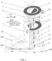
FIG. 1 is a schematic structural diagram of Embodiment One of the present invention; -
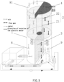
FIG. 2 is a schematic structural diagram of Embodiment Two of the present invention; -
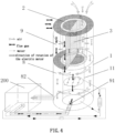
FIG. 3 is a schematic structural diagram of Embodiment Three of the present invention; -
FIG. 4 is a schematic structural diagram of Embodiment Four of the present invention. - The present invention is described in detail below with reference to the drawings and embodiments.
- As shown in
FIG. 1 , the further recovery system for residual heat of flue gas as installed in this embodiment comprises ahousing 1, a rotatingcore 2, apartition plate 3, abaffle plate 4, aspray device 5, a water-water heat exchanger 6, and air-fluegas heat exchanger 7. Therein, thehousing 1 is an upright thin-wall hollow cylinder. The rotatingcore 2 is an upright thick-wall hollow cylinder. The side wall of the rotatingcore 2 is honeycomb-like, the honeycomb openings of which are horizontal, and the honeycomb surfaces are coated with desiccant material(s). The rotatingcore 2 is coaxially installed in the upper part of thehousing 1 and capable of rotating around its central axis. Thepartition plate 3 passes through the central axis of thehousing 1 and the rotatingcore 2 to divide the internal space of thehousing 1 and the rotatingcore 2 into anair flow channel 8 and a fluegas flow channel 9. A plurality ofbaffle plates 4 are respectively disposed between the top of thehousing 1 and the top of the rotatingcore 2, between the top of the rotatingcore 2 and the top of thepartition plate 3 on the flue-gas-flow-channel side 9, between the bottom of the rotatingcore 2 and thepartition plate 3 on the air-flow-channel side 8, and between the bottom of the rotatingcore 2 and thehousing 1 on the flue-gas-flow-channel side 9. The top of the rotatingcore 2 on the air-flow-channel side 8 forms an airflow channel inlet 81, and an airflow channel outlet 82 is provided in the lower wall of thehousing 1 on the air-flow-channel side 8. The airflow channel outlet 82 is connected with the air inlet of anatural gas boiler 200. A flue gasflow channel inlet 91 and a flue gasflow channel outlet 92 are respectively installed in the lower wall and upper wall of thehousing 1 on the flue-gas-flow-channel side 9. The flue gasflow channel inlet 91 is connected with the flue gas outlet of thenatural gas boiler 200. Since the flue gasflow channel outlet 92 is provided in the wall of thehousing 1 and opened facing the surroundings, it can prevent the discharged flue gas from mixing with the air entering the airflow channel inlet 81. Thespray device 5 is installed in the fluegas flow channel 9 at a lower part inside thehousing 1. The liquid distributor(s) 51 of thespray device 5 is/are disposed near the side wall of thehousing 1 and thepartition plate 3. The water-water heat exchanger 6 is disposed outside thehousing 1. The heat release unit of the water-water heat exchanger 6 is connected to the water inlet and the water outlet of thespray device 5. The heat absorption unit of the water-water heat exchanger 6 is connected to anexternal backwater pipe 300. An air-fluegas heat exchanger 7 is fixedly disposed on thepartition plate 3 in the lower part of thehousing 1. The heat release unit of the air-fluegas heat exchanger 7 is positioned in theair flow channel 8 and the heat absorption unit thereof is positioned in the fluegas flow channel 9. - When the further recovery system for residual heat of flue gas in this embodiment is in use, first, the outdoor low-temperature and low-humidity air in winter enters the
air flow channel 8 inside the rotatingcore 2 from the airflow channel inlet 81, and then is diffused into theair flow channel 8 between the rotatingcore 2 and thehousing 1 via the side wall of the rotatingcore 2. Then the air is heated and humidified as it goes through the side wall of the rotatingcore 2. The heated and humidified air continues to flow downward along theair flow channel 8 and further exchanges heat with the heat release unit of the air-fluegas heat exchanger 7 in theair flow channel 8 in the lower part of thehousing 1, thus turning into the overheated state. Finally, the overheated air is discharged from the airflow channel outlet 82 into thenatural gas boiler 200 as combustion-supporting air. Natural gas and combustion-supporting air are mixed and burned in thenatural gas boiler 200, and the generated flue gas enters the fluegas flow channel 9 in the lower part of thehousing 1 via the flue gasflow channel inlet 91. The liquid distributor(s) 51 of thespray device 5 spray(s) the spray water to perform heat-and-mass exchange with high-temperature flue gas. The flue gas flows upward along the fluegas flow channel 9 after cooled and dehumidified, and is further cooled as it goes through the heat absorption unit of the air-fluegas heat exchanger 7. The flue gas continues to flow upward and enters the fluegas flow channel 9 inside therotating core 2 and then diffused into the fluegas flow channel 9 between therotating core 2 and thehousing 1 via the side wall of therotating core 2. The flue gas is cooled and dehumidified when passing therotating core 2 and finally discharged into the atmosphere via the flue gasflow channel outlet 92. Therotating core 2 rotates around its central axis at a certain speed. The portion of therotating core 2 in the fluegas flow channel 9 absorbs the heat and moisture of the flue gas, and then rotates into theair flow channel 8 to transfer the absorbed heat and moisture to the air to preheat and humidify the air. After exchanging heat with the flue gas, the spray water enters the heat release unit of the water-water heat exchanger 6 and exchanges heat with the low-temperature backwater in the heat absorption unit. After preheated by the spray water, the low-temperature backwater enters thenatural gas boiler 200 to be heated, and then enters aheat user 400 as high-temperature supplying water to release heat, thereby finishing a complete thermal cycle. - The further recovery system for residual heat of flue gas as installed in the present invention actually realizes two-stage recovery for residual heat of flue gas, wherein the lower spray device, the water-water heat exchanger and the air-flue gas heat exchanger constitute the first-stage flue gas recovery device, and the upper rotating core coated with desiccant material(s) constitutes the second-stage flue gas recovery device.
- As shown in
FIG. 2 , the further recovery system for residual heat of flue gas as provided in this embodiment has a similar structure to that in Embodiment One, except that the liquid distributor(s) 51 of thespray device 5 is/are installed above the flue gasflow channel inlet 91 in this embodiment, so that the flue gas and the spray water exchange heat in the form of counterflows, in order to obtain a better heat exchange effect. - In the above embodiment, the air-flue
gas heat exchanger 7 is disposed below the liquid distributor(s) 51 of thespray device 5. While the flue gas flows through theflow channel 9, the flue gas firstly exchanges heat with the heat absorption unit of the air-fluegas heat exchanger 7, and then enters thespray device 5 to exchange heat with the spray water. - As shown in
FIG. 3 , the further recovery system for residual heat of flue gas as provided in this embodiment has the similar structure to that in Embodiment One, except therotating core 2 in this embodiment including acentral axis 21 and a surroundingrotating wheel 22. Therotating wheel 22 has a honeycomb structure and the honeycomb openings are vertical. The outer diameter of therotating wheel 22 matches the inner diameter of thehousing 1. Since the air can only flow vertically in therotating wheel 22, thepartition plate 3 is only installed in thehousing 1 under therotating core 2, dividing the internal space of the lower part of the housing into anair flow channel 8 and a fluegas flow channel 9, and thebaffle plate 4 only needs to be disposed between the top of therotating core 2 and the top of thehousing 1 in the flue-gas-flow-channel 9. When the further recovery system for residual heat of flue gas as provided in this embodiment is in use, the air directly goes downward through therotating wheel 22 and is directly heated and humidified, and then enters theair flow channel 8 in the lower part of thehousing 1. After the flue gas goes through thespray device 5 and the air-fluegas heat exchanger 7, it flows vertically upward through therotating wheel 22 and is discharged to the atmosphere after being cooled and dehumidified. Thus the flow channel structure is more direct and simple. - As shown in
FIG.4 , the further recovery system for residual heat of flue gas as provided in this embodiment has the similar structure to that in Embodiment One, except that the structure is further simplified in this embodiment. The air-fluegas heat exchanger 7 is omitted and aninner housing 11 is coaxially inserted in thehousing 1 and positioned under therotating core 2. Theinner housing 11 is a thin-wall hollow cylinder. The internal cavity of theinner housing 11 is connected with the internal cavity of therotating core 2. Thepartition plates 3 are only installed in the upper part of thehousing 1 and in the cavity of therotating core 2. The internal cavity of theinner housing 11 serves as the fluegas flow channel 9, and the cavity between theinner housing 11 and thehousing 1 serves as theair flow channel 8. Namely, there is the fluegas flow channel 9 in the middle and theair flow channel 8 in the periphery. The flue gasflow channel inlet 91 is provided in the lower wall of theinner housing 11. When the further recovery system for residual heat of flue gas in this embodiment is in use, the air flows downwards after being heated and humidified by therotating core 2 in the upper part and flows in the cavity between theinner housing 11 and thehousing 1, and finally the air enters thenatural gas boiler 200 via the airflow channel outlet 82. The flue gas directly enters the fluegas flow channel 9 in theinner housing 11 via the flue gasflow channel inlet 91. After being cooled and dehumidified by the spray water, the flue gas flows upward and is discharged after being further cooled and dehumidified by therotating core 2. Due to the large temperature difference between the flue gas and the air in the lower part of thehousing 1, the side wall surface of theinner housing 11 can even preheat the air. - The above embodiments are only used to illustrate the present invention. All of the structures, installations and connection methods of components are variable. Any equivalent transformation and improvement based on the present invention should not be excluded from the protection of the present invention.
Claims (5)
- A further recovery system for residual heat of flue gas, comprising:a housing (1) of upright thin-wall hollow cylinder shape,a rotating core (2) coaxially installed in the upper part of the housing (1) and capable of rotating around its central axis,a partition plate (3) installed in the housing (1) and passing through the central axis of the housing (1) and the rotating core (2),a baffle plate (4),a spray device (5), anda water-water heat exchanger (6) with a heat release unit connected to a water inlet and a water outlet of the spray device (5);wherein the rotating core (2) is a upright thick-wall hollow cylinder, the longitudinal cross section of the side wall of the rotating core (2) is honeycomb-like, the interiors of which are coated with desiccant material(s), the partition plate (3) divides the internal space of the housing (1) and the rotating (2) core into an air flow channel (8) and a flue gas flow channel (9), a plurality of baffle plates (4) are respectively installed between the top of the housing (1) and the top of the rotating core (2), between the top of the rotating (2) core and the top of the partition plate (3) on the flue-gas-flow-channel side, between the bottom of the rotating core (2) and the partition plate (3) on the air-flow-channel side, and between the bottom of the rotating core (2) and the housing (1) on the flue-gas-flow-channel side, the top of the rotating core (2) on the air-flow-channel side forms an air flow channel inlet (81), an air flow channel outlet (82) is provided in the lower wall of the housing (1) on the air-flow-channel side, a flue gas flow channel inlet (91) and a flue gas flow channel outlet (92) are respectively provided in the lower wall and upper wall of the housing (1) on the flue-gas-flow-channel side, and the spray device (5) is installed in the flue gas flow channel (9) in the lower part of the housing (1).
- The further recovery system for residual heat of flue gas according to claim 1, wherein liquid distributor(s) (51) of the spray device (5) is/are disposed near the side wall of the housing (1) and the partition plate (3).
- The further recovery system for residual heat of flue gas according to claim 2, wherein the liquid distributor(s) (51) of the spray device (5) is/are disposed above the flue gas flow channel inlet (91).
- The further recovery system for residual heat of flue gas according to claim 1 or 2, wherein the partition plate (3) in the lower part of the housing (1) further has an air-flue gas heat exchanger (7) fixedly arranged thereon, and a heat release unit of the air-flue gas heat exchanger (7) is positioned in the air flow channel (8) and a heat absorption unit thereof is positioned in the flue gas flow channel (9).
- The further recovery system for residual heat of flue gas according to claim 3, wherein the partition plate (3) in the lower part of the housing (1) further has an air-flue gas heat exchanger (7) fixedly arranged thereon, and the heat exchange end of the air-flue gas heat exchanger (7) is positioned in the air flow channel (8) and the heat absorption end thereof is positioned in the flue gas flow channel (9); the air-flue gas heat exchanger (7) is disposed below the liquid distributor(s) (51) of the spray device (5).
Applications Claiming Priority (2)
| Application Number | Priority Date | Filing Date | Title |
|---|---|---|---|
| CN201711260072.XA CN109869734B (en) | 2017-12-04 | 2017-12-04 | Flue gas waste heat degree of depth recovery system |
| PCT/CN2017/116395 WO2019109375A1 (en) | 2017-12-04 | 2017-12-15 | Deep recovery system for residual heat of fume |
Publications (3)
| Publication Number | Publication Date |
|---|---|
| EP3722669A1 EP3722669A1 (en) | 2020-10-14 |
| EP3722669A4 EP3722669A4 (en) | 2021-10-27 |
| EP3722669B1 true EP3722669B1 (en) | 2024-03-27 |
Family
ID=66750690
Family Applications (1)
| Application Number | Title | Priority Date | Filing Date |
|---|---|---|---|
| EP17933925.4A Active EP3722669B1 (en) | 2017-12-04 | 2017-12-15 | Deep recovery system for residual heat of fume |
Country Status (4)
| Country | Link |
|---|---|
| EP (1) | EP3722669B1 (en) |
| JP (1) | JP6933414B2 (en) |
| CN (1) | CN109869734B (en) |
| WO (1) | WO2019109375A1 (en) |
Families Citing this family (4)
| Publication number | Priority date | Publication date | Assignee | Title |
|---|---|---|---|---|
| CN111336852A (en) * | 2020-03-21 | 2020-06-26 | 张淑荣 | Natural gas flue gas latent heat recovery plant |
| CN112361368B (en) * | 2020-09-30 | 2022-05-03 | 山东岱荣节能环保科技有限公司 | A middle switching device for flue gas waste heat recovery |
| CN114151818A (en) * | 2021-10-29 | 2022-03-08 | 庄典平 | Energy-saving waste heat recovery equipment for boiler |
| CN114893788A (en) * | 2022-05-09 | 2022-08-12 | 杨志伟 | Waste heat recovery device with tail gas treatment structure for energy conservation and consumption reduction of thermal power plant |
Family Cites Families (11)
| Publication number | Priority date | Publication date | Assignee | Title |
|---|---|---|---|---|
| US4252181A (en) * | 1977-03-15 | 1981-02-24 | Johannes Kirchmeier | Heat recovering fan |
| JPS5778924A (en) * | 1980-11-05 | 1982-05-17 | H Ii I:Kk | Rotary type dehumidifier |
| JPS57187592A (en) * | 1981-05-12 | 1982-11-18 | Toshimi Kuma | Tubular centrifugal type heat exchanger |
| JPH0657297B2 (en) * | 1985-10-23 | 1994-08-03 | 新菱冷熱工業株式会社 | Method and apparatus for regenerating hygroscopic liquid |
| SE9103730L (en) * | 1991-12-17 | 1992-12-07 | Svenska Rotor Maskiner Ab | PROCEDURES PROVIDE OPTIMUM ENERGY EXCHANGE IN REGENERATIVE HEAT EXCHANGE, WHEN HEAT TRANSMISSION ELEMENTS ARE STARTED WITH WATER |
| ES2334262T3 (en) * | 2005-09-27 | 2010-03-08 | Dall Energy Holding Aps | METHOD AND SYSTEM FOR WATER HEATING BASED ON HOT GASES. |
| CN101275771B (en) * | 2008-04-02 | 2010-06-16 | 北京亚都空气污染治理技术有限公司 | Heat-reclaiming device of rotating wheel dehumidifier and thermal recovery method using the same |
| CN202237766U (en) * | 2011-09-17 | 2012-05-30 | 马成果 | Desulfurization, dedusting and copious cooling exchange all-in-one machine |
| CN104654480A (en) * | 2015-01-04 | 2015-05-27 | 深圳市奥宇节能技术股份有限公司 | Low-grade afterheat recycling type energy-saving dehumidifying unit |
| CN107036113A (en) * | 2017-04-13 | 2017-08-11 | 保定清科节能技术推广有限公司 | A kind of flue gas heat recovery system |
| CN107238097B (en) * | 2017-06-26 | 2019-01-04 | 清华大学 | A kind of boiler smoke-gas residual-heat recovering device |
-
2017
- 2017-12-04 CN CN201711260072.XA patent/CN109869734B/en active Active
- 2017-12-15 EP EP17933925.4A patent/EP3722669B1/en active Active
- 2017-12-15 JP JP2020530683A patent/JP6933414B2/en active Active
- 2017-12-15 WO PCT/CN2017/116395 patent/WO2019109375A1/en unknown
Also Published As
| Publication number | Publication date |
|---|---|
| CN109869734B (en) | 2020-05-12 |
| JP6933414B2 (en) | 2021-09-08 |
| CN109869734A (en) | 2019-06-11 |
| WO2019109375A1 (en) | 2019-06-13 |
| EP3722669A4 (en) | 2021-10-27 |
| JP2021505835A (en) | 2021-02-18 |
| EP3722669A1 (en) | 2020-10-14 |
Similar Documents
| Publication | Publication Date | Title |
|---|---|---|
| EP3722669B1 (en) | Deep recovery system for residual heat of fume | |
| CN109260914B (en) | Flue gas whitening system and process utilizing air circulation | |
| CN108426264B (en) | Device for removing colored smoke plume through synergistic dedusting of recovered smoke waste heat | |
| CN108800975A (en) | A kind of flue gas cooling heat exchanger of the desulfurization duct mouth with refrigerating plant | |
| CN204694131U (en) | A kind of complex phase-change heat exchanger | |
| CN203036658U (en) | Boiler flue gas waste heat multipurpose utilization system | |
| CN205191619U (en) | Heat -pipe heat exchanger | |
| CN208893800U (en) | A kind of flue gas takes off white device | |
| CN208887158U (en) | A kind of absorption heat pump processing equipment | |
| CN208704021U (en) | A kind of hot air type gas heating stove recycling steam humidification | |
| CN208839334U (en) | A kind of device for eliminating boiler desulfurization flue gas white plume | |
| CN207990904U (en) | A kind of reverse-flow fresh air heat exchanger Total heat exchange core | |
| CN100498090C (en) | Ventilating device with temperature-humidity dual exchange | |
| CN202868844U (en) | Modularized radiation heat transfer terminal and waste heat recovery radiation pipe network heat pump system | |
| CN109827421A (en) | A kind of superhigh temperature industrial heat pump drying unit | |
| CN206256033U (en) | A kind of natual gas dehydrate unit of utilization new energy thermal regeneration | |
| CN209246644U (en) | A kind of heat-exchanger rig and the drying pipe support using the heat-exchanger rig | |
| CN208920088U (en) | A kind of flue gas dehumidifying and water-recorvery apparatus using the cooling cooling supply of indirect evaporation type | |
| CN211316221U (en) | Waste heat recovery boiler integrated device | |
| CN207379346U (en) | Flue gas waste heat recoverer | |
| CN102901269B (en) | Multipurpose direct coal-fired machine for refrigeration, heat supply and bathing | |
| CN202562342U (en) | Fin-type double phase steel heat pipe heat exchanger and corresponding flue gas desulfurization equipment | |
| CN202745813U (en) | Mine well ventilation air and water drainage heat energy comprehensive utilization system | |
| CN112484138A (en) | Domestic natural gas heating system | |
| CN208443029U (en) | Membrane type total heat exchanger for water vapor heat recovery |
Legal Events
| Date | Code | Title | Description |
|---|---|---|---|
| STAA | Information on the status of an ep patent application or granted ep patent |
Free format text: STATUS: THE INTERNATIONAL PUBLICATION HAS BEEN MADE |
|
| PUAI | Public reference made under article 153(3) epc to a published international application that has entered the european phase |
Free format text: ORIGINAL CODE: 0009012 |
|
| STAA | Information on the status of an ep patent application or granted ep patent |
Free format text: STATUS: REQUEST FOR EXAMINATION WAS MADE |
|
| 17P | Request for examination filed |
Effective date: 20200623 |
|
| AK | Designated contracting states |
Kind code of ref document: A1 Designated state(s): AL AT BE BG CH CY CZ DE DK EE ES FI FR GB GR HR HU IE IS IT LI LT LU LV MC MK MT NL NO PL PT RO RS SE SI SK SM TR |
|
| AX | Request for extension of the european patent |
Extension state: BA ME |
|
| DAV | Request for validation of the european patent (deleted) | ||
| DAX | Request for extension of the european patent (deleted) | ||
| A4 | Supplementary search report drawn up and despatched |
Effective date: 20210929 |
|
| RIC1 | Information provided on ipc code assigned before grant |
Ipc: F24H 9/00 20060101ALI20210923BHEP Ipc: F23L 7/00 20060101ALI20210923BHEP Ipc: F28D 19/04 20060101ALI20210923BHEP Ipc: F24H 8/00 20060101ALI20210923BHEP Ipc: F23J 15/06 20060101AFI20210923BHEP |
|
| GRAP | Despatch of communication of intention to grant a patent |
Free format text: ORIGINAL CODE: EPIDOSNIGR1 |
|
| STAA | Information on the status of an ep patent application or granted ep patent |
Free format text: STATUS: GRANT OF PATENT IS INTENDED |
|
| RIC1 | Information provided on ipc code assigned before grant |
Ipc: F24H 9/00 20060101ALI20230927BHEP Ipc: F23L 7/00 20060101ALI20230927BHEP Ipc: F28D 19/04 20060101ALI20230927BHEP Ipc: F24H 8/00 20060101ALI20230927BHEP Ipc: F23J 15/06 20060101AFI20230927BHEP |
|
| INTG | Intention to grant announced |
Effective date: 20231024 |
|
| GRAS | Grant fee paid |
Free format text: ORIGINAL CODE: EPIDOSNIGR3 |
|
| GRAA | (expected) grant |
Free format text: ORIGINAL CODE: 0009210 |
|
| STAA | Information on the status of an ep patent application or granted ep patent |
Free format text: STATUS: THE PATENT HAS BEEN GRANTED |
|
| AK | Designated contracting states |
Kind code of ref document: B1 Designated state(s): AL AT BE BG CH CY CZ DE DK EE ES FI FR GB GR HR HU IE IS IT LI LT LU LV MC MK MT NL NO PL PT RO RS SE SI SK SM TR |
|
| REG | Reference to a national code |
Ref country code: GB Ref legal event code: FG4D |
|
| REG | Reference to a national code |
Ref country code: CH Ref legal event code: EP |
|
| REG | Reference to a national code |
Ref country code: DE Ref legal event code: R096 Ref document number: 602017080507 Country of ref document: DE |
|
| REG | Reference to a national code |
Ref country code: IE Ref legal event code: FG4D |
|
| PG25 | Lapsed in a contracting state [announced via postgrant information from national office to epo] |
Ref country code: LT Free format text: LAPSE BECAUSE OF FAILURE TO SUBMIT A TRANSLATION OF THE DESCRIPTION OR TO PAY THE FEE WITHIN THE PRESCRIBED TIME-LIMIT Effective date: 20240327 |
|
| REG | Reference to a national code |
Ref country code: LT Ref legal event code: MG9D |
|
| PG25 | Lapsed in a contracting state [announced via postgrant information from national office to epo] |
Ref country code: GR Free format text: LAPSE BECAUSE OF FAILURE TO SUBMIT A TRANSLATION OF THE DESCRIPTION OR TO PAY THE FEE WITHIN THE PRESCRIBED TIME-LIMIT Effective date: 20240628 |
|
| PG25 | Lapsed in a contracting state [announced via postgrant information from national office to epo] |
Ref country code: HR Free format text: LAPSE BECAUSE OF FAILURE TO SUBMIT A TRANSLATION OF THE DESCRIPTION OR TO PAY THE FEE WITHIN THE PRESCRIBED TIME-LIMIT Effective date: 20240327 Ref country code: RS Free format text: LAPSE BECAUSE OF FAILURE TO SUBMIT A TRANSLATION OF THE DESCRIPTION OR TO PAY THE FEE WITHIN THE PRESCRIBED TIME-LIMIT Effective date: 20240627 |
|
| PG25 | Lapsed in a contracting state [announced via postgrant information from national office to epo] |
Ref country code: RS Free format text: LAPSE BECAUSE OF FAILURE TO SUBMIT A TRANSLATION OF THE DESCRIPTION OR TO PAY THE FEE WITHIN THE PRESCRIBED TIME-LIMIT Effective date: 20240627 Ref country code: NO Free format text: LAPSE BECAUSE OF FAILURE TO SUBMIT A TRANSLATION OF THE DESCRIPTION OR TO PAY THE FEE WITHIN THE PRESCRIBED TIME-LIMIT Effective date: 20240627 Ref country code: LT Free format text: LAPSE BECAUSE OF FAILURE TO SUBMIT A TRANSLATION OF THE DESCRIPTION OR TO PAY THE FEE WITHIN THE PRESCRIBED TIME-LIMIT Effective date: 20240327 Ref country code: HR Free format text: LAPSE BECAUSE OF FAILURE TO SUBMIT A TRANSLATION OF THE DESCRIPTION OR TO PAY THE FEE WITHIN THE PRESCRIBED TIME-LIMIT Effective date: 20240327 Ref country code: GR Free format text: LAPSE BECAUSE OF FAILURE TO SUBMIT A TRANSLATION OF THE DESCRIPTION OR TO PAY THE FEE WITHIN THE PRESCRIBED TIME-LIMIT Effective date: 20240628 Ref country code: FI Free format text: LAPSE BECAUSE OF FAILURE TO SUBMIT A TRANSLATION OF THE DESCRIPTION OR TO PAY THE FEE WITHIN THE PRESCRIBED TIME-LIMIT Effective date: 20240327 Ref country code: BG Free format text: LAPSE BECAUSE OF FAILURE TO SUBMIT A TRANSLATION OF THE DESCRIPTION OR TO PAY THE FEE WITHIN THE PRESCRIBED TIME-LIMIT Effective date: 20240327 |
|
| REG | Reference to a national code |
Ref country code: NL Ref legal event code: MP Effective date: 20240327 |
|
| PG25 | Lapsed in a contracting state [announced via postgrant information from national office to epo] |
Ref country code: SE Free format text: LAPSE BECAUSE OF FAILURE TO SUBMIT A TRANSLATION OF THE DESCRIPTION OR TO PAY THE FEE WITHIN THE PRESCRIBED TIME-LIMIT Effective date: 20240327 Ref country code: LV Free format text: LAPSE BECAUSE OF FAILURE TO SUBMIT A TRANSLATION OF THE DESCRIPTION OR TO PAY THE FEE WITHIN THE PRESCRIBED TIME-LIMIT Effective date: 20240327 |
|
| PG25 | Lapsed in a contracting state [announced via postgrant information from national office to epo] |
Ref country code: NL Free format text: LAPSE BECAUSE OF FAILURE TO SUBMIT A TRANSLATION OF THE DESCRIPTION OR TO PAY THE FEE WITHIN THE PRESCRIBED TIME-LIMIT Effective date: 20240327 |
|
| REG | Reference to a national code |
Ref country code: AT Ref legal event code: MK05 Ref document number: 1670253 Country of ref document: AT Kind code of ref document: T Effective date: 20240327 |
|
| PG25 | Lapsed in a contracting state [announced via postgrant information from national office to epo] |
Ref country code: NL Free format text: LAPSE BECAUSE OF FAILURE TO SUBMIT A TRANSLATION OF THE DESCRIPTION OR TO PAY THE FEE WITHIN THE PRESCRIBED TIME-LIMIT Effective date: 20240327 |