EP3722626A1 - Hybrid metallic/composite joint with separate internal bearing - Google Patents
Hybrid metallic/composite joint with separate internal bearing Download PDFInfo
- Publication number
- EP3722626A1 EP3722626A1 EP19215266.8A EP19215266A EP3722626A1 EP 3722626 A1 EP3722626 A1 EP 3722626A1 EP 19215266 A EP19215266 A EP 19215266A EP 3722626 A1 EP3722626 A1 EP 3722626A1
- Authority
- EP
- European Patent Office
- Prior art keywords
- metallic
- bearing
- conical
- fitting
- internal
- Prior art date
- Legal status (The legal status is an assumption and is not a legal conclusion. Google has not performed a legal analysis and makes no representation as to the accuracy of the status listed.)
- Granted
Links
Images



Classifications
-
- F—MECHANICAL ENGINEERING; LIGHTING; HEATING; WEAPONS; BLASTING
- F16—ENGINEERING ELEMENTS AND UNITS; GENERAL MEASURES FOR PRODUCING AND MAINTAINING EFFECTIVE FUNCTIONING OF MACHINES OR INSTALLATIONS; THERMAL INSULATION IN GENERAL
- F16C—SHAFTS; FLEXIBLE SHAFTS; ELEMENTS OR CRANKSHAFT MECHANISMS; ROTARY BODIES OTHER THAN GEARING ELEMENTS; BEARINGS
- F16C19/00—Bearings with rolling contact, for exclusively rotary movement
- F16C19/22—Bearings with rolling contact, for exclusively rotary movement with bearing rollers essentially of the same size in one or more circular rows, e.g. needle bearings
- F16C19/34—Bearings with rolling contact, for exclusively rotary movement with bearing rollers essentially of the same size in one or more circular rows, e.g. needle bearings for both radial and axial load
- F16C19/38—Bearings with rolling contact, for exclusively rotary movement with bearing rollers essentially of the same size in one or more circular rows, e.g. needle bearings for both radial and axial load with two or more rows of rollers
- F16C19/383—Bearings with rolling contact, for exclusively rotary movement with bearing rollers essentially of the same size in one or more circular rows, e.g. needle bearings for both radial and axial load with two or more rows of rollers with tapered rollers, i.e. rollers having essentially the shape of a truncated cone
- F16C19/385—Bearings with rolling contact, for exclusively rotary movement with bearing rollers essentially of the same size in one or more circular rows, e.g. needle bearings for both radial and axial load with two or more rows of rollers with tapered rollers, i.e. rollers having essentially the shape of a truncated cone with two rows, i.e. double-row tapered roller bearings
- F16C19/386—Bearings with rolling contact, for exclusively rotary movement with bearing rollers essentially of the same size in one or more circular rows, e.g. needle bearings for both radial and axial load with two or more rows of rollers with tapered rollers, i.e. rollers having essentially the shape of a truncated cone with two rows, i.e. double-row tapered roller bearings in O-arrangement
-
- F—MECHANICAL ENGINEERING; LIGHTING; HEATING; WEAPONS; BLASTING
- F16—ENGINEERING ELEMENTS AND UNITS; GENERAL MEASURES FOR PRODUCING AND MAINTAINING EFFECTIVE FUNCTIONING OF MACHINES OR INSTALLATIONS; THERMAL INSULATION IN GENERAL
- F16C—SHAFTS; FLEXIBLE SHAFTS; ELEMENTS OR CRANKSHAFT MECHANISMS; ROTARY BODIES OTHER THAN GEARING ELEMENTS; BEARINGS
- F16C7/00—Connecting-rods or like links pivoted at both ends; Construction of connecting-rod heads
- F16C7/02—Constructions of connecting-rods with constant length
- F16C7/026—Constructions of connecting-rods with constant length made of fibre reinforced resin
-
- B—PERFORMING OPERATIONS; TRANSPORTING
- B29—WORKING OF PLASTICS; WORKING OF SUBSTANCES IN A PLASTIC STATE IN GENERAL
- B29C—SHAPING OR JOINING OF PLASTICS; SHAPING OF MATERIAL IN A PLASTIC STATE, NOT OTHERWISE PROVIDED FOR; AFTER-TREATMENT OF THE SHAPED PRODUCTS, e.g. REPAIRING
- B29C66/00—General aspects of processes or apparatus for joining preformed parts
- B29C66/70—General aspects of processes or apparatus for joining preformed parts characterised by the composition, physical properties or the structure of the material of the parts to be joined; Joining with non-plastics material
- B29C66/72—General aspects of processes or apparatus for joining preformed parts characterised by the composition, physical properties or the structure of the material of the parts to be joined; Joining with non-plastics material characterised by the structure of the material of the parts to be joined
- B29C66/721—Fibre-reinforced materials
-
- F—MECHANICAL ENGINEERING; LIGHTING; HEATING; WEAPONS; BLASTING
- F16—ENGINEERING ELEMENTS AND UNITS; GENERAL MEASURES FOR PRODUCING AND MAINTAINING EFFECTIVE FUNCTIONING OF MACHINES OR INSTALLATIONS; THERMAL INSULATION IN GENERAL
- F16C—SHAFTS; FLEXIBLE SHAFTS; ELEMENTS OR CRANKSHAFT MECHANISMS; ROTARY BODIES OTHER THAN GEARING ELEMENTS; BEARINGS
- F16C7/00—Connecting-rods or like links pivoted at both ends; Construction of connecting-rod heads
- F16C7/02—Constructions of connecting-rods with constant length
-
- B—PERFORMING OPERATIONS; TRANSPORTING
- B64—AIRCRAFT; AVIATION; COSMONAUTICS
- B64C—AEROPLANES; HELICOPTERS
- B64C1/00—Fuselages; Constructional features common to fuselages, wings, stabilising surfaces or the like
- B64C2001/0054—Fuselage structures substantially made from particular materials
- B64C2001/0072—Fuselage structures substantially made from particular materials from composite materials
-
- B—PERFORMING OPERATIONS; TRANSPORTING
- B64—AIRCRAFT; AVIATION; COSMONAUTICS
- B64C—AEROPLANES; HELICOPTERS
- B64C1/00—Fuselages; Constructional features common to fuselages, wings, stabilising surfaces or the like
- B64C2001/0054—Fuselage structures substantially made from particular materials
- B64C2001/0081—Fuselage structures substantially made from particular materials from metallic materials
-
- B—PERFORMING OPERATIONS; TRANSPORTING
- B64—AIRCRAFT; AVIATION; COSMONAUTICS
- B64C—AEROPLANES; HELICOPTERS
- B64C25/00—Alighting gear
- B64C25/02—Undercarriages
- B64C25/08—Undercarriages non-fixed, e.g. jettisonable
- B64C25/10—Undercarriages non-fixed, e.g. jettisonable retractable, foldable, or the like
-
- B—PERFORMING OPERATIONS; TRANSPORTING
- B64—AIRCRAFT; AVIATION; COSMONAUTICS
- B64C—AEROPLANES; HELICOPTERS
- B64C25/00—Alighting gear
- B64C25/32—Alighting gear characterised by elements which contact the ground or similar surface
- B64C25/58—Arrangements or adaptations of shock-absorbers or springs
-
- B—PERFORMING OPERATIONS; TRANSPORTING
- B64—AIRCRAFT; AVIATION; COSMONAUTICS
- B64C—AEROPLANES; HELICOPTERS
- B64C25/00—Alighting gear
- B64C25/32—Alighting gear characterised by elements which contact the ground or similar surface
- B64C25/58—Arrangements or adaptations of shock-absorbers or springs
- B64C25/60—Oleo legs
-
- F—MECHANICAL ENGINEERING; LIGHTING; HEATING; WEAPONS; BLASTING
- F16—ENGINEERING ELEMENTS AND UNITS; GENERAL MEASURES FOR PRODUCING AND MAINTAINING EFFECTIVE FUNCTIONING OF MACHINES OR INSTALLATIONS; THERMAL INSULATION IN GENERAL
- F16C—SHAFTS; FLEXIBLE SHAFTS; ELEMENTS OR CRANKSHAFT MECHANISMS; ROTARY BODIES OTHER THAN GEARING ELEMENTS; BEARINGS
- F16C2326/00—Articles relating to transporting
- F16C2326/43—Aeroplanes; Helicopters
-
- Y—GENERAL TAGGING OF NEW TECHNOLOGICAL DEVELOPMENTS; GENERAL TAGGING OF CROSS-SECTIONAL TECHNOLOGIES SPANNING OVER SEVERAL SECTIONS OF THE IPC; TECHNICAL SUBJECTS COVERED BY FORMER USPC CROSS-REFERENCE ART COLLECTIONS [XRACs] AND DIGESTS
- Y02—TECHNOLOGIES OR APPLICATIONS FOR MITIGATION OR ADAPTATION AGAINST CLIMATE CHANGE
- Y02T—CLIMATE CHANGE MITIGATION TECHNOLOGIES RELATED TO TRANSPORTATION
- Y02T50/00—Aeronautics or air transport
- Y02T50/40—Weight reduction
Definitions
- the present disclosure relates to composite tube assemblies and methods of manufacture of composite tube assemblies, and, more specifically, to aircraft retractable landing gear systems having metallic component interfaces to composite tubes.
- Composite tubes are often used due to their high strength and low weight in industries and applications where weight is a significant design factor, such as in the aircraft and automotive industries.
- Landing gear supports an aircraft while the aircraft is on the ground and tend to comprise metallic components capable of withstanding the high structural loads environment of aircraft landing.
- Landing gear may include one or more wheels and a shock strut assembly in order to attenuate the forces associated with landing or ground operations.
- Composite tubes may be used to interface between metallic structures and thereby tend to reduce component weight.
- the structures may be subjected to axial tensile and compressive loads, shear loads, bending loads, and torsional loads. Working loads may be transmitted directly through to the composite structure which may benefit of a connector having an optimized load path between metallic structures and the composite structure.
- a metallic-composite joint fitting comprising a frustoconical internal bearing, an internal bolt coupled within a bore of the frustoconical internal bearing, a metallic end fitting coupled to the internal bolt, wherein the metallic end fitting comprises a bearing portion disposed within the bore, a conical sleeve disposed about the frustoconical internal bearing, and an external nut coupled to the metallic end fitting and the conical sleeve.
- a composite structure is coupled between the frustoconical internal bearing and the conical sleeve.
- the composite structure comprises a cylindrical portion and a conical end portion.
- the conical end portion is coupled relatively between the frustoconical internal bearing at a first conical bearing surface and the conical sleeve at a second conical bearing surface.
- the conical end portion is flared.
- the bearing portion contacts the frustoconical internal bearing at a cylindrical bearing surface.
- the internal bolt is integral to the frustoconical internal bearing.
- the metallic end fitting is coupled to the internal bolt at an internally threaded surface of the metallic end fitting.
- the external nut is contacted with the conical sleeve via an end washer.
- the metallic end fitting is removably coupled to the internal bolt.
- a landing gear system comprising a shock strut coupled to an axle, a wheel coupled to the axle, and a metallic-composite joint fitting comprising a frustoconical internal bearing, an internal bolt coupled within a bore of the frustoconical internal bearing, a metallic end fitting coupled to the internal bolt, wherein the metallic end fitting comprises a bearing portion disposed within the bore, a conical sleeve disposed about the frustoconical internal bearing, and an external nut coupled to the metallic end fitting and the conical sleeve.
- a composite structure is coupled between the frustoconical internal bearing and the conical sleeve.
- the composite structure comprises a cylindrical portion and a conical end portion.
- the conical end portion is coupled relatively between the frustoconical internal bearing at a first conical bearing surface and the conical sleeve at a second conical bearing surface.
- the conical end portion is flared.
- the bearing portion contacts the frustoconical internal bearing at a cylindrical bearing surface.
- the internal bolt is integral to the frustoconical internal bearing.
- the metallic end fitting is coupled to the internal bolt at an internally threaded surface of the metallic end fitting.
- the external nut is contacted with the conical sleeve via an end washer.
- a method of joining a composite structure and a metallic end fitting comprises coupling an internal bolt within a bore of a frustoconical internal bearing, wrapping the composite structure over the frustoconical internal bearing to form a conical end portion, disposing a conical sleeve over the conical end portion to enclose the conical end portion between a first conical bearing surface and a second conical bearing surface, inserting a bearing portion of the metallic end fitting into the bore of the frustoconical internal bearing and coupling the internal bolt to an internally threaded surface of the metallic end fitting, and coupling an external nut to an externally threaded surface of the metallic end fitting and contacting the external nut with the conical sleeve.
- any of the method or process descriptions may be executed in any order and are not necessarily limited to the order presented.
- any reference to singular includes plural embodiments, and any reference to more than one component or step may include a singular embodiment or step.
- any reference to attached, fixed, coupled, connected or the like may include permanent, removable, temporary, partial, full and/or any other possible attachment option.
- any reference to without contact (or similar phrases) may also include reduced contact or minimal contact. Surface shading lines may be used throughout the figures to denote different parts but not necessarily to denote the same or different materials.
- an aircraft 10 in accordance with various embodiments may comprise aircraft systems, for example, one or more landing gear such as landing gear 12, landing gear 14 and landing gear 16.
- Landing gear 12, landing gear 14 and landing gear 16 may generally support aircraft 10 when aircraft 10 is not flying, allowing aircraft 10 to taxi, take off, and land without damage and may comprise wheels and an oleo strut, also referred to as a shock strut, comprising a strut cylinder and a strut piston filled with a hydraulic fluid.
- landing gear 12 may include wheels 18 coupled by an axle 20 and a shock strut assembly 22 comprising a metallic-composite joint fitting 200.
- metallic-composite joint fitting 200 (hereinafter “fitting") is illustrated in planar cross section of the XY-plane.
- Fitting 200 comprises a coupling between a metallic end fitting 202 and a composite structure 204.
- Composite structure 204 comprises a conical end portion 206 wrapped about a frustoconical internal bearing 208.
- the conical end portion 206 may engage with the frustoconical internal bearing 208 along a first conical bearing surface 210.
- the conical end portion 206 of the composite structure 204 may flare outward from the first conical bearing surface 210.
- the conical end portion 206 may increase in radial (i.e., X-axis) thickness, as compared to the radial thickness of a cylindrical portion 207 of the composite structure 204, progressing along the Y-axis from the cylindrical portion 207 toward the tip of the conical end portion 206.
- the metallic end fitting 202 may comprise a shaft 212 and a coupling feature 214.
- the coupling feature 214 includes an externally threaded surface 216 at the outer diameter of the coupling feature 214 configured to engage with an external nut 220.
- the externally threaded surface 216 extends from the shaft 212 toward a bearing portion 218 relatively below (along the Y-axis) the externally threaded surface 216.
- the bearing portion 218 is inserted into a bore 222 through the frustoconical internal bearing 208 and engages with a cylindrical bearing surface 224 which defines the inner diameter of the frustoconical internal bearing 208.
- the coupling feature 214 includes an internally threaded surface 226 at the inner diameter of the coupling feature 214.
- the internally threaded surface 226 may extend along the inner diameter of the coupling feature 214 radially inward of the bearing portion 218.
- the internally threaded surface 226 may be configured to engage with a shank 228 of an internal bolt 230.
- Internal bolt 230 may extend into bore 222 of the frustoconical internal bearing 208.
- the head 232 of internal bolt 230 may seat against a shoulder 234 within the bore 222 and thereby tend to inhibit the metallic end fitting 202 from translating axially outward (along the Y-axis) with respect to the frustoconical internal bearing 208 and maintain the engagement of the bearing portion 218 along the cylindrical bearing surface 224.
- the head 232 of internal bolt 230 may be configured to inhibit rotation of the internal bolt with respect to the frustoconical internal bearing 208.
- head 232 may be relatively D-shaped and the bore 222 may include a relatively flat portion configured to interface with a flat portion of the D-shaped head tending thereby to inhibit rotation of the internal bolt 230 with respect to the frustoconical internal bearing 208.
- an internal bolt may be integral to a frustoconical internal bearing or may be fixedly coupled to a frustoconical internal bearing such as, for example, by welding or bonding.
- a conical sleeve 236 may be disposed about the frustoconical internal bearing 208 over the conical end portion 206 of the composite structure 204.
- the conical sleeve 236 may lie radially outward of the conical end portion 206 and the frustoconical internal bearing 208 may lie radially inward of the conical end portion 206 and the conical sleeve 236.
- the conical end portion 206 may be sandwiched between the frustoconical internal bearing 208 at first conical bearing surface 210 and the conical sleeve 236 at a second conical bearing surface 238.
- external nut 220 may be contacted with the conical sleeve 236, the conical end portion 206, and the frustoconical internal bearing 208 via an end washer 240.
- the external nut 220 tends to inhibit the metallic end fitting 202 from translating axially inward (along the Y-axis) with respect to the frustoconical internal bearing 208 by generating an interference at the second conical bearing surface 238 between the conical sleeve 236 and the conical end portion 206.
- fitting 200 may be optimized to carry compressive and tension loads via threaded surfaces while carrying bending loads at non-threaded bearing surfaces. In this regard, fitting 200 may tend to benefit of improved bending load performance.
- Fitting 200 is illustrated in cross section overlaid with optimized load paths 300 for axial tension, axial compression, and radial bending loads applied at metallic end fitting 202.
- a compressive force F C applied at the metallic end fitting 202 travels as shown by arrows 302 through externally threaded surface 216 into external nut 220.
- External nut 220 transmits F C through end washer 240 into conical sleeve 236.
- the conical sleeve 236 transmits the compressive force F C through the second conical bearing surface 238 into the conical end portion 206 and thereby the cylindrical portion 207 of composite structure 204.
- a tension force F T applied at the metallic end fitting 202 is transmitted via internally threaded surface 226 into shank 228 of internal bolt 230.
- Internal bolt 230 transmits the tension force F T through shoulder 234 into frustoconical internal bearing 208.
- the frustoconical internal bearing 208 passes the tension force F T through the first conical bearing surface 210 into the conical end portion 206 and thereby the cylindrical portion 207 of composite structure 204.
- a bending load F B is applied at the metallic end fitting 202 and travels as shown by arrow 306 entirely (i.e., greater than 95% of the bending load) through cylindrical bearing surface 224 into the frustoconical internal bearing 208.
- the frustoconical internal bearing 208 passes the bending load through the first conical bearing surface 210 into the conical end portion 206.
- Head 232 of internal bolt 230 may have relatively reduced diameter in comparison to the diameter of the bore 222 and thereby engage primarily axially (along the Y-axis) the frustoconical internal bearing 208 at the shoulder 234.
- radial contact (along the X-axis) between the frustoconical internal bearing 208 and the head 232 under a bearing load may be minimized or eliminated.
- the fitting 200 may thereby tend to inhibit bearing loads from passing through any of the threaded surfaces (226, 216).
- a method 400 of joining a composite structure 204 and a metallic end fitting 202 may comprise coupling an internal bolt 230 within a bore 222 of a frustoconical internal bearing 208 (step 402).
- Method 400 includes wrapping the composite structure 204 over the frustoconical internal bearing 208 to form a conical end portion 206 (step 404).
- Method 400 includes disposing a conical sleeve 236 over the conical end portion 206 to enclose the conical end portion 206 between a first conical bearing surface 210 and a second conical bearing surface 238 (step 406).
- Method 400 includes inserting a bearing portion of the metallic end fitting 202 into the bore of the frustoconical internal bearing 208 and coupling the internal bolt 230 to an internally threaded surface 226 of the metallic end fitting 202 (step 408).
- Method 400 includes coupling an external nut 220 to an externally threaded surface 216 of the metallic end fitting 202 and contacting the external nut 220 with the conical sleeve 236 (step 410).
- the external nut 220 may be contacted with the conical sleeve 236 via an end washer 240.
- references to "various embodiments,” “one embodiment,” “an embodiment,” “an example embodiment,” etc. indicate that the embodiment described may include a particular feature, structure, or characteristic, but every embodiment may not necessarily include the particular feature, structure, or characteristic. Moreover, such phrases are not necessarily referring to the same embodiment. Further, when a particular feature, structure, or characteristic is described in connection with an embodiment, it is submitted that it is within the knowledge of one skilled in the art to affect such feature, structure, or characteristic in connection with other embodiments whether or not explicitly described. After reading the description, it will be apparent to one skilled in the relevant art(s) how to implement the disclosure in alternative embodiments.
Landscapes
- Engineering & Computer Science (AREA)
- Mechanical Engineering (AREA)
- General Engineering & Computer Science (AREA)
- Aviation & Aerospace Engineering (AREA)
- Connection Of Plates (AREA)
- Bolts, Nuts, And Washers (AREA)
Abstract
Description
- The present disclosure relates to composite tube assemblies and methods of manufacture of composite tube assemblies, and, more specifically, to aircraft retractable landing gear systems having metallic component interfaces to composite tubes.
- Composite tubes are often used due to their high strength and low weight in industries and applications where weight is a significant design factor, such as in the aircraft and automotive industries. Landing gear supports an aircraft while the aircraft is on the ground and tend to comprise metallic components capable of withstanding the high structural loads environment of aircraft landing. Landing gear may include one or more wheels and a shock strut assembly in order to attenuate the forces associated with landing or ground operations. Composite tubes may be used to interface between metallic structures and thereby tend to reduce component weight. The structures may be subjected to axial tensile and compressive loads, shear loads, bending loads, and torsional loads. Working loads may be transmitted directly through to the composite structure which may benefit of a connector having an optimized load path between metallic structures and the composite structure.
- In various embodiments, a metallic-composite joint fitting is provided comprising a frustoconical internal bearing, an internal bolt coupled within a bore of the frustoconical internal bearing, a metallic end fitting coupled to the internal bolt, wherein the metallic end fitting comprises a bearing portion disposed within the bore, a conical sleeve disposed about the frustoconical internal bearing, and an external nut coupled to the metallic end fitting and the conical sleeve.
- In various embodiments, a composite structure is coupled between the frustoconical internal bearing and the conical sleeve. In various embodiments, the composite structure comprises a cylindrical portion and a conical end portion. In various embodiments, the conical end portion is coupled relatively between the frustoconical internal bearing at a first conical bearing surface and the conical sleeve at a second conical bearing surface. In various embodiments, the conical end portion is flared. In various embodiments, the bearing portion contacts the frustoconical internal bearing at a cylindrical bearing surface. In various embodiments, the internal bolt is integral to the frustoconical internal bearing. In various embodiments, the metallic end fitting is coupled to the internal bolt at an internally threaded surface of the metallic end fitting. In various embodiments, the external nut is contacted with the conical sleeve via an end washer. In various embodiments, the metallic end fitting is removably coupled to the internal bolt.
- In various embodiments, a landing gear system is provided comprising a shock strut coupled to an axle, a wheel coupled to the axle, and a metallic-composite joint fitting comprising a frustoconical internal bearing, an internal bolt coupled within a bore of the frustoconical internal bearing, a metallic end fitting coupled to the internal bolt, wherein the metallic end fitting comprises a bearing portion disposed within the bore, a conical sleeve disposed about the frustoconical internal bearing, and an external nut coupled to the metallic end fitting and the conical sleeve.
- In various embodiments, a composite structure is coupled between the frustoconical internal bearing and the conical sleeve. In various embodiments, the composite structure comprises a cylindrical portion and a conical end portion. In various embodiments, the conical end portion is coupled relatively between the frustoconical internal bearing at a first conical bearing surface and the conical sleeve at a second conical bearing surface. In various embodiments, the conical end portion is flared. In various embodiments, the bearing portion contacts the frustoconical internal bearing at a cylindrical bearing surface. In various embodiments, the internal bolt is integral to the frustoconical internal bearing. In various embodiments, the metallic end fitting is coupled to the internal bolt at an internally threaded surface of the metallic end fitting. In various embodiments, the external nut is contacted with the conical sleeve via an end washer.
- In various embodiments, a method of joining a composite structure and a metallic end fitting comprises coupling an internal bolt within a bore of a frustoconical internal bearing, wrapping the composite structure over the frustoconical internal bearing to form a conical end portion, disposing a conical sleeve over the conical end portion to enclose the conical end portion between a first conical bearing surface and a second conical bearing surface, inserting a bearing portion of the metallic end fitting into the bore of the frustoconical internal bearing and coupling the internal bolt to an internally threaded surface of the metallic end fitting, and coupling an external nut to an externally threaded surface of the metallic end fitting and contacting the external nut with the conical sleeve.
- The foregoing features and elements may be combined in various combinations without exclusivity, unless expressly indicated otherwise. These features and elements as well as the operation thereof will become more apparent in light of the following description and the accompanying drawings. It should be understood, however, the following description and drawings are intended to be exemplary in nature and non-limiting.
- The subject matter of the present disclosure is particularly pointed out and distinctly claimed in the concluding portion of the specification. A more complete understanding of the present disclosure, however, may best be obtained by referring to the detailed description and claims when considered in connection with the figures, wherein like numerals denote like elements.
-
FIG. 1 illustrates an aircraft, in accordance with various embodiments; -
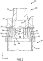
FIG. 2 illustrates a metallic-composite joint fitting, in accordance with various embodiments; -
FIG. 3 illustrates load paths in a metallic-composite joint fitting, in accordance with various embodiments; and -
FIG. 4 illustrates a method of joining a composite structure and a metallic end fitting, in accordance with various embodiments. - All ranges and ratio limits disclosed herein may be combined. It is to be understood that unless specifically stated otherwise, references to "a," "an," and/or "the" may include one or more than one and that reference to an item in the singular may also include the item in the plural.
- The detailed description of exemplary embodiments herein makes reference to the accompanying drawings, which show exemplary embodiments by way of illustration. While these exemplary embodiments are described in sufficient detail to enable those skilled in the art to practice the exemplary embodiments of the disclosure, it should be understood that other embodiments may be realized and that logical changes and adaptations in design and construction may be made in accordance with this disclosure and the teachings herein. Thus, the detailed description herein is presented for purposes of illustration only and not limitation.
- The scope of the disclosure is defined by the appended claims and their legal equivalents rather than by merely the examples described. For example, the steps recited in any of the method or process descriptions may be executed in any order and are not necessarily limited to the order presented. Furthermore, any reference to singular includes plural embodiments, and any reference to more than one component or step may include a singular embodiment or step. Also, any reference to attached, fixed, coupled, connected or the like may include permanent, removable, temporary, partial, full and/or any other possible attachment option. Additionally, any reference to without contact (or similar phrases) may also include reduced contact or minimal contact. Surface shading lines may be used throughout the figures to denote different parts but not necessarily to denote the same or different materials.
- With reference to
FIG. 1 , anaircraft 10 in accordance with various embodiments may comprise aircraft systems, for example, one or more landing gear such aslanding gear 12,landing gear 14 andlanding gear 16.Landing gear 12,landing gear 14 andlanding gear 16 may generally supportaircraft 10 whenaircraft 10 is not flying, allowingaircraft 10 to taxi, take off, and land without damage and may comprise wheels and an oleo strut, also referred to as a shock strut, comprising a strut cylinder and a strut piston filled with a hydraulic fluid. For example,landing gear 12 may includewheels 18 coupled by anaxle 20 and ashock strut assembly 22 comprising a metallic-composite joint fitting 200. - In various embodiments and with additional reference to
FIG. 2 , metallic-composite joint fitting 200 (hereinafter "fitting") is illustrated in planar cross section of the XY-plane. Fitting 200 comprises a coupling between ametallic end fitting 202 and acomposite structure 204.Composite structure 204 comprises aconical end portion 206 wrapped about a frustoconicalinternal bearing 208. In this regard, theconical end portion 206 may engage with the frustoconicalinternal bearing 208 along a first conical bearingsurface 210. In various embodiments, theconical end portion 206 of thecomposite structure 204 may flare outward from the first conical bearingsurface 210. Stated another way, theconical end portion 206 may increase in radial (i.e., X-axis) thickness, as compared to the radial thickness of acylindrical portion 207 of thecomposite structure 204, progressing along the Y-axis from thecylindrical portion 207 toward the tip of theconical end portion 206. - In various embodiments, the
metallic end fitting 202 may comprise ashaft 212 and acoupling feature 214. Thecoupling feature 214 includes an externally threadedsurface 216 at the outer diameter of thecoupling feature 214 configured to engage with anexternal nut 220. The externally threadedsurface 216 extends from theshaft 212 toward abearing portion 218 relatively below (along the Y-axis) the externally threadedsurface 216. Thebearing portion 218 is inserted into abore 222 through the frustoconicalinternal bearing 208 and engages with a cylindrical bearingsurface 224 which defines the inner diameter of the frustoconicalinternal bearing 208. Thecoupling feature 214 includes an internally threadedsurface 226 at the inner diameter of thecoupling feature 214. In various embodiments, the internally threadedsurface 226 may extend along the inner diameter of thecoupling feature 214 radially inward of the bearingportion 218. The internally threadedsurface 226 may be configured to engage with ashank 228 of aninternal bolt 230. -
Internal bolt 230 may extend intobore 222 of the frustoconicalinternal bearing 208. In various embodiments, thehead 232 ofinternal bolt 230 may seat against ashoulder 234 within thebore 222 and thereby tend to inhibit the metallic end fitting 202 from translating axially outward (along the Y-axis) with respect to the frustoconicalinternal bearing 208 and maintain the engagement of the bearingportion 218 along thecylindrical bearing surface 224. In various embodiments, thehead 232 ofinternal bolt 230 may be configured to inhibit rotation of the internal bolt with respect to the frustoconicalinternal bearing 208. For example,head 232 may be relatively D-shaped and thebore 222 may include a relatively flat portion configured to interface with a flat portion of the D-shaped head tending thereby to inhibit rotation of theinternal bolt 230 with respect to the frustoconicalinternal bearing 208. In various embodiments, an internal bolt may be integral to a frustoconical internal bearing or may be fixedly coupled to a frustoconical internal bearing such as, for example, by welding or bonding. - In various embodiments, a
conical sleeve 236 may be disposed about the frustoconicalinternal bearing 208 over theconical end portion 206 of thecomposite structure 204. Theconical sleeve 236 may lie radially outward of theconical end portion 206 and the frustoconicalinternal bearing 208 may lie radially inward of theconical end portion 206 and theconical sleeve 236. In this regard, theconical end portion 206 may be sandwiched between the frustoconicalinternal bearing 208 at firstconical bearing surface 210 and theconical sleeve 236 at a secondconical bearing surface 238. In various embodiments,external nut 220 may be contacted with theconical sleeve 236, theconical end portion 206, and the frustoconicalinternal bearing 208 via anend washer 240. In this regard, theexternal nut 220 tends to inhibit the metallic end fitting 202 from translating axially inward (along the Y-axis) with respect to the frustoconicalinternal bearing 208 by generating an interference at the secondconical bearing surface 238 between theconical sleeve 236 and theconical end portion 206. - In various embodiments and with additional reference to
FIG. 3 , fitting 200 may be optimized to carry compressive and tension loads via threaded surfaces while carrying bending loads at non-threaded bearing surfaces. In this regard, fitting 200 may tend to benefit of improved bending load performance. Fitting 200 is illustrated in cross section overlaid with optimizedload paths 300 for axial tension, axial compression, and radial bending loads applied at metallic end fitting 202. A compressive force FC applied at the metallic end fitting 202 travels as shown byarrows 302 through externally threadedsurface 216 intoexternal nut 220.External nut 220 transmits FC throughend washer 240 intoconical sleeve 236. Theconical sleeve 236 transmits the compressive force FC through the secondconical bearing surface 238 into theconical end portion 206 and thereby thecylindrical portion 207 ofcomposite structure 204. As shown byarrows 304, a tension force FT applied at the metallic end fitting 202 is transmitted via internally threadedsurface 226 intoshank 228 ofinternal bolt 230.Internal bolt 230 transmits the tension force FT throughshoulder 234 into frustoconicalinternal bearing 208. The frustoconicalinternal bearing 208 passes the tension force FT through the firstconical bearing surface 210 into theconical end portion 206 and thereby thecylindrical portion 207 ofcomposite structure 204. - A bending load FB is applied at the metallic end fitting 202 and travels as shown by
arrow 306 entirely (i.e., greater than 95% of the bending load) throughcylindrical bearing surface 224 into the frustoconicalinternal bearing 208. The frustoconicalinternal bearing 208 passes the bending load through the firstconical bearing surface 210 into theconical end portion 206.Head 232 ofinternal bolt 230 may have relatively reduced diameter in comparison to the diameter of thebore 222 and thereby engage primarily axially (along the Y-axis) the frustoconicalinternal bearing 208 at theshoulder 234. In this regard, radial contact (along the X-axis) between the frustoconicalinternal bearing 208 and thehead 232 under a bearing load may be minimized or eliminated. The fitting 200 may thereby tend to inhibit bearing loads from passing through any of the threaded surfaces (226, 216). - In various embodiments, a
method 400 of joining acomposite structure 204 and a metallic end fitting 202 may comprise coupling aninternal bolt 230 within abore 222 of a frustoconical internal bearing 208 (step 402).Method 400 includes wrapping thecomposite structure 204 over the frustoconicalinternal bearing 208 to form a conical end portion 206 (step 404).Method 400 includes disposing aconical sleeve 236 over theconical end portion 206 to enclose theconical end portion 206 between a firstconical bearing surface 210 and a second conical bearing surface 238 (step 406).Method 400 includes inserting a bearing portion of the metallic end fitting 202 into the bore of the frustoconicalinternal bearing 208 and coupling theinternal bolt 230 to an internally threadedsurface 226 of the metallic end fitting 202 (step 408).Method 400 includes coupling anexternal nut 220 to an externally threadedsurface 216 of the metallic end fitting 202 and contacting theexternal nut 220 with the conical sleeve 236 (step 410). In various embodiments, theexternal nut 220 may be contacted with theconical sleeve 236 via anend washer 240. - Benefits and other advantages have been described herein with regard to specific embodiments. Furthermore, the connecting lines shown in the various figures contained herein are intended to represent exemplary functional relationships and/or physical couplings between the various elements. It should be noted that many alternative or additional functional relationships or physical connections may be present in a practical system. However, the benefits, advantages, and any elements that may cause any benefit or advantage to occur or become more pronounced are not to be construed as critical, required, or essential features or elements of the disclosure. The scope of the disclosure is accordingly to be limited by nothing other than the appended claims, in which reference to an element in the singular is not intended to mean "one and only one" unless explicitly so stated, but rather "one or more." Moreover, where a phrase similar to "at least one of A, B, or C" is used in the claims, it is intended that the phrase be interpreted to mean that A alone may be present in an embodiment, B alone may be present in an embodiment, C alone may be present in an embodiment, or that any combination of the elements A, B and C may be present in a single embodiment; for example, A and B, A and C, B and C, or A and B and C.
- Systems, methods and apparatus are provided herein. In the detailed description herein, references to "various embodiments," "one embodiment," "an embodiment," "an example embodiment," etc., indicate that the embodiment described may include a particular feature, structure, or characteristic, but every embodiment may not necessarily include the particular feature, structure, or characteristic. Moreover, such phrases are not necessarily referring to the same embodiment. Further, when a particular feature, structure, or characteristic is described in connection with an embodiment, it is submitted that it is within the knowledge of one skilled in the art to affect such feature, structure, or characteristic in connection with other embodiments whether or not explicitly described. After reading the description, it will be apparent to one skilled in the relevant art(s) how to implement the disclosure in alternative embodiments.
- Furthermore, no element, component, or method step in the present disclosure is intended to be dedicated to the public regardless of whether the element, component, or method step is explicitly recited in the claims. As used herein, the terms "comprises," "comprising," or any other variation thereof, are intended to cover a non-exclusive inclusion, such that a process, method, article, or apparatus that comprises a list of elements does not include only those elements but may include other elements not expressly listed or inherent to such process, method, article, or apparatus.
Claims (12)
- A metallic-composite joint fitting (200), comprising:a frustoconical internal bearing (208);an internal bolt (230) coupled within a bore (222) of the frustoconical internal bearing;a metallic end fitting (202) configured to couple to the internal bolt, wherein the metallic end fitting comprises a bearing portion (218) configured to be disposed within the bore;a conical sleeve (236) disposed about the frustoconical internal bearing; andan external nut (220) configured to couple to the metallic end fitting and the conical sleeve.
- The metallic-composite joint fitting of claim 1, wherein a composite structure is coupled between the frustoconical internal bearing and the conical sleeve.
- The metallic-composite joint fitting of claim 2, wherein the composite structure comprises a cylindrical portion and a conical end portion.
- The metallic-composite joint fitting of claim 3, wherein the conical end portion is coupled relatively between the frustoconical internal bearing at a first conical bearing surface and the conical sleeve at a second conical bearing surface.
- The metallic-composite joint fitting of claim 3 or 4, wherein the conical end portion is flared.
- The metallic-composite joint fitting of any preceding claim, wherein the bearing portion contacts the frustoconical internal bearing at a cylindrical bearing surface.
- The metallic-composite joint fitting of any preceding claim, wherein the internal bolt is integral to the frustoconical internal bearing.
- The metallic-composite joint fitting of any preceding claim, wherein the metallic end fitting is coupled to the internal bolt at an internally threaded surface of the metallic end fitting.
- The metallic-composite joint fitting of any preceding claim, wherein the external nut is contacted with the conical sleeve via an end washer.
- The metallic-composite joint fitting of any preceding claim, wherein the metallic end fitting is removably coupled to the internal bolt.
- A landing gear system, comprising:a shock strut coupled to an axle (20);a wheel (18) coupled to the axle; andthe metallic-composite joint fitting according to any preceding claim,wherein the internal bolt is coupled within a bore of the frustoconical internal bearing; andthe external nut is coupled to the metallic end fitting and the conical sleeve.
- A method (400) of joining a composite structure (204) and a metallic end fitting (202), comprising:coupling (402) an internal bolt (230) within a bore (222) of a frustoconical internal bearing;wrapping (404) the composite structure over the frustoconical internal bearing to form a conical end portion (206);disposing (406) a conical sleeve (236) over the conical end portion to enclose the conical end portion between a first conical bearing surface (210) and a second conical bearing surface (238);inserting (408) a bearing portion of the metallic end fitting into the bore of the frustoconical internal bearing and coupling the internal bolt to an internally threaded surface of the metallic end fitting; andcoupling (410) an external nut (220) to an externally threaded surface of the metallic end fitting and contacting the external nut with the conical sleeve.
Applications Claiming Priority (1)
| Application Number | Priority Date | Filing Date | Title |
|---|---|---|---|
| US16/381,762 US10626917B1 (en) | 2019-04-11 | 2019-04-11 | Hybrid metallic/composite joint with separate internal bearing |
Publications (2)
| Publication Number | Publication Date |
|---|---|
| EP3722626A1 true EP3722626A1 (en) | 2020-10-14 |
| EP3722626B1 EP3722626B1 (en) | 2021-11-17 |
Family
ID=68886851
Family Applications (1)
| Application Number | Title | Priority Date | Filing Date |
|---|---|---|---|
| EP19215266.8A Active EP3722626B1 (en) | 2019-04-11 | 2019-12-11 | Hybrid metallic/composite joint with separate internal bearing |
Country Status (2)
| Country | Link |
|---|---|
| US (1) | US10626917B1 (en) |
| EP (1) | EP3722626B1 (en) |
Families Citing this family (3)
| Publication number | Priority date | Publication date | Assignee | Title |
|---|---|---|---|---|
| EP3611390B1 (en) * | 2018-08-16 | 2020-12-23 | Crompton Technology Group Limited | Composite structure having a tapered joint and a method for making the same |
| US11512738B2 (en) * | 2019-04-11 | 2022-11-29 | Goodrich Corporation | Hybrid metallic/composite joint with separate internal bearing |
| US20250251003A1 (en) * | 2024-02-01 | 2025-08-07 | B/E Aerospace, Inc. | Joint for composite tubular rods |
Citations (3)
| Publication number | Priority date | Publication date | Assignee | Title |
|---|---|---|---|---|
| US4411114A (en) * | 1980-12-29 | 1983-10-25 | M.A.N. Maschinenfabrik Augsburg-Nurnberg Aktiengesellschaft | Compression-tension strut |
| US4848957A (en) * | 1987-07-04 | 1989-07-18 | Jamco Corporation | Coupling for plastic tube |
| US20160272304A1 (en) * | 2015-03-20 | 2016-09-22 | Goodrich Corporation | Composite Actuator Rod End Assembly |
Family Cites Families (25)
| Publication number | Priority date | Publication date | Assignee | Title |
|---|---|---|---|---|
| US1003530A (en) | 1911-06-19 | 1911-09-19 | William Randolph Smith | Balancing and steering device for airships. |
| US3638979A (en) * | 1969-11-19 | 1972-02-01 | Uniroyal Inc | Force-transmitting systems |
| US4353268A (en) * | 1976-03-10 | 1982-10-12 | Avions Marcel Dassault-Breguet Aviation | Connecting rods |
| GB1572179A (en) * | 1976-11-17 | 1980-07-23 | Ml Aviation Co Ltd | Webbing strops |
| FR2469604A1 (en) * | 1979-11-08 | 1981-05-22 | Rech Meca Appliquee | CONNECTING ROD OR THE LIKE HAVING A HOLLOW BODY |
| US4469730A (en) * | 1982-12-30 | 1984-09-04 | The Boeing Company | Composite base structure and end fitting joint and method |
| US4647078A (en) | 1985-12-19 | 1987-03-03 | Hercules, Incorporated | Metal to composite tubular joints |
| US5303958A (en) | 1991-10-31 | 1994-04-19 | The Deutsch Company | Axially swaged fitting with composite swaging ring |
| US5318374A (en) | 1992-09-23 | 1994-06-07 | The Boeing Company | Composite tube structure |
| RU2154767C1 (en) | 1999-12-28 | 2000-08-20 | Закрытое акционерное общество "Пласт" | Connection of composite-material tubes |
| US6734805B2 (en) | 2000-08-07 | 2004-05-11 | Abb Vetco Gray Inc. | Composite pipe telemetry conduit |
| US20090101328A1 (en) | 2004-09-28 | 2009-04-23 | Advanced Composite Products & Technology, Inc. | Composite drill pipe and method of forming same |
| US8205315B2 (en) | 2006-11-01 | 2012-06-26 | Tyee Aircraft | Composite tube assemblies and methods of forming the same |
| NZ561410A (en) | 2007-09-11 | 2010-04-30 | Parker Hannifin Gmbh | End-fittings for composite tubes, method for joining fittings to the ends of composite tubes and composite tubes incorporating end-fittings |
| GB0722933D0 (en) | 2007-11-23 | 2008-01-02 | Dewhurst Mike | Mechanical connection between composite tubular structure and an end fitting of any engineering material |
| RU2484353C1 (en) | 2012-04-17 | 2013-06-10 | Общество С Ограниченной Ответственностью "Группа Полимертепло" | Polymer tube joint assembly |
| DK2713060T3 (en) | 2012-10-01 | 2019-02-18 | Ge Energy Power Conversion Technology Ltd | Mechanical devices |
| EP3381665B1 (en) | 2017-03-31 | 2023-03-22 | Crompton Technology Group Limited | Composite structural component with captive mechanical joint |
| US9726325B2 (en) | 2014-05-01 | 2017-08-08 | Goodrich Corporation | Composite tube assemblies and methods |
| US9568040B2 (en) | 2014-06-02 | 2017-02-14 | Goodrich Corporation | Struts and methods utilizing a locking collar nut |
| US10190607B2 (en) | 2015-01-30 | 2019-01-29 | Goodrich Corporation | Composite actuator piston head assembly |
| EP3133298B1 (en) * | 2015-08-21 | 2019-02-06 | Crompton Technology Group Limited | Connector |
| GB2546280A (en) | 2016-01-12 | 2017-07-19 | Crompton Tech Group Ltd | Composite tubular structure |
| CN107044572B (en) | 2017-06-22 | 2022-12-27 | 中国海洋大学 | Prepressing self-tightening joint for ocean composite flexible pipe |
| CN107687558B (en) | 2017-09-04 | 2020-02-18 | 中国海洋大学 | A combined buckling stopper for a submarine fiber-reinforced composite flexible pipe |
-
2019
- 2019-04-11 US US16/381,762 patent/US10626917B1/en active Active
- 2019-12-11 EP EP19215266.8A patent/EP3722626B1/en active Active
Patent Citations (3)
| Publication number | Priority date | Publication date | Assignee | Title |
|---|---|---|---|---|
| US4411114A (en) * | 1980-12-29 | 1983-10-25 | M.A.N. Maschinenfabrik Augsburg-Nurnberg Aktiengesellschaft | Compression-tension strut |
| US4848957A (en) * | 1987-07-04 | 1989-07-18 | Jamco Corporation | Coupling for plastic tube |
| US20160272304A1 (en) * | 2015-03-20 | 2016-09-22 | Goodrich Corporation | Composite Actuator Rod End Assembly |
Also Published As
| Publication number | Publication date |
|---|---|
| US10626917B1 (en) | 2020-04-21 |
| EP3722626B1 (en) | 2021-11-17 |
Similar Documents
| Publication | Publication Date | Title |
|---|---|---|
| US10626917B1 (en) | Hybrid metallic/composite joint with separate internal bearing | |
| US10539174B2 (en) | Composite joint assembly | |
| US10066649B2 (en) | Hybrid metallic/composite piston head joint | |
| EP3213992A1 (en) | Aircraft landing gear assembly | |
| US12092137B2 (en) | Hybrid metallic/composite joint with enhanced strength | |
| US10486799B2 (en) | Rod end | |
| US11534984B2 (en) | Hybrid metallic/composite joint with integral bearing | |
| EP3722621B1 (en) | Hybrid metallic/composite joint with separate internal bearing and coupling flange | |
| EP3260369B1 (en) | Metallic composite joint | |
| EP3882137A1 (en) | Magnetic self-centering shimmy damper | |
| EP3708853B1 (en) | Retention systems for light weight actuator glands | |
| EP3090943A1 (en) | Landing gear including a bogie beam assembly and method for coupling an axle to a bogie beam thereof | |
| US20230264811A1 (en) | Integral steering motor and collar for landing gear | |
| US11713794B2 (en) | Piston housing assembly | |
| US11851167B2 (en) | Integral steering motor and collar for landing gear | |
| US11498666B2 (en) | Shock strut assemblies for landing gear | |
| US12246824B2 (en) | Nose wheel steering systems and methods | |
| EP4273041A1 (en) | Integral steering motor and collar for landing gear | |
| CA3046005A1 (en) | Composite structure having a tapered joint and a method for making the same |
Legal Events
| Date | Code | Title | Description |
|---|---|---|---|
| PUAI | Public reference made under article 153(3) epc to a published international application that has entered the european phase |
Free format text: ORIGINAL CODE: 0009012 |
|
| STAA | Information on the status of an ep patent application or granted ep patent |
Free format text: STATUS: THE APPLICATION HAS BEEN PUBLISHED |
|
| AK | Designated contracting states |
Kind code of ref document: A1 Designated state(s): AL AT BE BG CH CY CZ DE DK EE ES FI FR GB GR HR HU IE IS IT LI LT LU LV MC MK MT NL NO PL PT RO RS SE SI SK SM TR |
|
| AX | Request for extension of the european patent |
Extension state: BA ME |
|
| STAA | Information on the status of an ep patent application or granted ep patent |
Free format text: STATUS: REQUEST FOR EXAMINATION WAS MADE |
|
| 17P | Request for examination filed |
Effective date: 20210409 |
|
| RBV | Designated contracting states (corrected) |
Designated state(s): AL AT BE BG CH CY CZ DE DK EE ES FI FR GB GR HR HU IE IS IT LI LT LU LV MC MK MT NL NO PL PT RO RS SE SI SK SM TR |
|
| GRAP | Despatch of communication of intention to grant a patent |
Free format text: ORIGINAL CODE: EPIDOSNIGR1 |
|
| STAA | Information on the status of an ep patent application or granted ep patent |
Free format text: STATUS: GRANT OF PATENT IS INTENDED |
|
| INTG | Intention to grant announced |
Effective date: 20210615 |
|
| GRAS | Grant fee paid |
Free format text: ORIGINAL CODE: EPIDOSNIGR3 |
|
| GRAA | (expected) grant |
Free format text: ORIGINAL CODE: 0009210 |
|
| STAA | Information on the status of an ep patent application or granted ep patent |
Free format text: STATUS: THE PATENT HAS BEEN GRANTED |
|
| AK | Designated contracting states |
Kind code of ref document: B1 Designated state(s): AL AT BE BG CH CY CZ DE DK EE ES FI FR GB GR HR HU IE IS IT LI LT LU LV MC MK MT NL NO PL PT RO RS SE SI SK SM TR |
|
| REG | Reference to a national code |
Ref country code: GB Ref legal event code: FG4D |
|
| REG | Reference to a national code |
Ref country code: IE Ref legal event code: FG4D |
|
| REG | Reference to a national code |
Ref country code: DE Ref legal event code: R096 Ref document number: 602019009357 Country of ref document: DE |
|
| REG | Reference to a national code |
Ref country code: AT Ref legal event code: REF Ref document number: 1448287 Country of ref document: AT Kind code of ref document: T Effective date: 20211215 |
|
| REG | Reference to a national code |
Ref country code: LT Ref legal event code: MG9D |
|
| REG | Reference to a national code |
Ref country code: NL Ref legal event code: MP Effective date: 20211117 |
|
| REG | Reference to a national code |
Ref country code: AT Ref legal event code: MK05 Ref document number: 1448287 Country of ref document: AT Kind code of ref document: T Effective date: 20211117 |
|
| PG25 | Lapsed in a contracting state [announced via postgrant information from national office to epo] |
Ref country code: RS Free format text: LAPSE BECAUSE OF FAILURE TO SUBMIT A TRANSLATION OF THE DESCRIPTION OR TO PAY THE FEE WITHIN THE PRESCRIBED TIME-LIMIT Effective date: 20211117 Ref country code: LT Free format text: LAPSE BECAUSE OF FAILURE TO SUBMIT A TRANSLATION OF THE DESCRIPTION OR TO PAY THE FEE WITHIN THE PRESCRIBED TIME-LIMIT Effective date: 20211117 Ref country code: FI Free format text: LAPSE BECAUSE OF FAILURE TO SUBMIT A TRANSLATION OF THE DESCRIPTION OR TO PAY THE FEE WITHIN THE PRESCRIBED TIME-LIMIT Effective date: 20211117 Ref country code: BG Free format text: LAPSE BECAUSE OF FAILURE TO SUBMIT A TRANSLATION OF THE DESCRIPTION OR TO PAY THE FEE WITHIN THE PRESCRIBED TIME-LIMIT Effective date: 20220217 Ref country code: AT Free format text: LAPSE BECAUSE OF FAILURE TO SUBMIT A TRANSLATION OF THE DESCRIPTION OR TO PAY THE FEE WITHIN THE PRESCRIBED TIME-LIMIT Effective date: 20211117 |
|
| PG25 | Lapsed in a contracting state [announced via postgrant information from national office to epo] |
Ref country code: IS Free format text: LAPSE BECAUSE OF FAILURE TO SUBMIT A TRANSLATION OF THE DESCRIPTION OR TO PAY THE FEE WITHIN THE PRESCRIBED TIME-LIMIT Effective date: 20220317 Ref country code: SE Free format text: LAPSE BECAUSE OF FAILURE TO SUBMIT A TRANSLATION OF THE DESCRIPTION OR TO PAY THE FEE WITHIN THE PRESCRIBED TIME-LIMIT Effective date: 20211117 Ref country code: PT Free format text: LAPSE BECAUSE OF FAILURE TO SUBMIT A TRANSLATION OF THE DESCRIPTION OR TO PAY THE FEE WITHIN THE PRESCRIBED TIME-LIMIT Effective date: 20220317 Ref country code: PL Free format text: LAPSE BECAUSE OF FAILURE TO SUBMIT A TRANSLATION OF THE DESCRIPTION OR TO PAY THE FEE WITHIN THE PRESCRIBED TIME-LIMIT Effective date: 20211117 Ref country code: NO Free format text: LAPSE BECAUSE OF FAILURE TO SUBMIT A TRANSLATION OF THE DESCRIPTION OR TO PAY THE FEE WITHIN THE PRESCRIBED TIME-LIMIT Effective date: 20220217 Ref country code: NL Free format text: LAPSE BECAUSE OF FAILURE TO SUBMIT A TRANSLATION OF THE DESCRIPTION OR TO PAY THE FEE WITHIN THE PRESCRIBED TIME-LIMIT Effective date: 20211117 Ref country code: LV Free format text: LAPSE BECAUSE OF FAILURE TO SUBMIT A TRANSLATION OF THE DESCRIPTION OR TO PAY THE FEE WITHIN THE PRESCRIBED TIME-LIMIT Effective date: 20211117 Ref country code: HR Free format text: LAPSE BECAUSE OF FAILURE TO SUBMIT A TRANSLATION OF THE DESCRIPTION OR TO PAY THE FEE WITHIN THE PRESCRIBED TIME-LIMIT Effective date: 20211117 Ref country code: GR Free format text: LAPSE BECAUSE OF FAILURE TO SUBMIT A TRANSLATION OF THE DESCRIPTION OR TO PAY THE FEE WITHIN THE PRESCRIBED TIME-LIMIT Effective date: 20220218 |
|
| PG25 | Lapsed in a contracting state [announced via postgrant information from national office to epo] |
Ref country code: SM Free format text: LAPSE BECAUSE OF FAILURE TO SUBMIT A TRANSLATION OF THE DESCRIPTION OR TO PAY THE FEE WITHIN THE PRESCRIBED TIME-LIMIT Effective date: 20211117 Ref country code: SK Free format text: LAPSE BECAUSE OF FAILURE TO SUBMIT A TRANSLATION OF THE DESCRIPTION OR TO PAY THE FEE WITHIN THE PRESCRIBED TIME-LIMIT Effective date: 20211117 Ref country code: RO Free format text: LAPSE BECAUSE OF FAILURE TO SUBMIT A TRANSLATION OF THE DESCRIPTION OR TO PAY THE FEE WITHIN THE PRESCRIBED TIME-LIMIT Effective date: 20211117 Ref country code: ES Free format text: LAPSE BECAUSE OF FAILURE TO SUBMIT A TRANSLATION OF THE DESCRIPTION OR TO PAY THE FEE WITHIN THE PRESCRIBED TIME-LIMIT Effective date: 20211117 Ref country code: EE Free format text: LAPSE BECAUSE OF FAILURE TO SUBMIT A TRANSLATION OF THE DESCRIPTION OR TO PAY THE FEE WITHIN THE PRESCRIBED TIME-LIMIT Effective date: 20211117 Ref country code: DK Free format text: LAPSE BECAUSE OF FAILURE TO SUBMIT A TRANSLATION OF THE DESCRIPTION OR TO PAY THE FEE WITHIN THE PRESCRIBED TIME-LIMIT Effective date: 20211117 Ref country code: CZ Free format text: LAPSE BECAUSE OF FAILURE TO SUBMIT A TRANSLATION OF THE DESCRIPTION OR TO PAY THE FEE WITHIN THE PRESCRIBED TIME-LIMIT Effective date: 20211117 |
|
| REG | Reference to a national code |
Ref country code: DE Ref legal event code: R097 Ref document number: 602019009357 Country of ref document: DE |
|
| PG25 | Lapsed in a contracting state [announced via postgrant information from national office to epo] |
Ref country code: MC Free format text: LAPSE BECAUSE OF FAILURE TO SUBMIT A TRANSLATION OF THE DESCRIPTION OR TO PAY THE FEE WITHIN THE PRESCRIBED TIME-LIMIT Effective date: 20211117 |
|
| PLBE | No opposition filed within time limit |
Free format text: ORIGINAL CODE: 0009261 |
|
| STAA | Information on the status of an ep patent application or granted ep patent |
Free format text: STATUS: NO OPPOSITION FILED WITHIN TIME LIMIT |
|
| REG | Reference to a national code |
Ref country code: BE Ref legal event code: MM Effective date: 20211231 |
|
| 26N | No opposition filed |
Effective date: 20220818 |
|
| PG25 | Lapsed in a contracting state [announced via postgrant information from national office to epo] |
Ref country code: LU Free format text: LAPSE BECAUSE OF NON-PAYMENT OF DUE FEES Effective date: 20211211 Ref country code: IE Free format text: LAPSE BECAUSE OF NON-PAYMENT OF DUE FEES Effective date: 20211211 Ref country code: AL Free format text: LAPSE BECAUSE OF FAILURE TO SUBMIT A TRANSLATION OF THE DESCRIPTION OR TO PAY THE FEE WITHIN THE PRESCRIBED TIME-LIMIT Effective date: 20211117 |
|
| PG25 | Lapsed in a contracting state [announced via postgrant information from national office to epo] |
Ref country code: SI Free format text: LAPSE BECAUSE OF FAILURE TO SUBMIT A TRANSLATION OF THE DESCRIPTION OR TO PAY THE FEE WITHIN THE PRESCRIBED TIME-LIMIT Effective date: 20211117 Ref country code: BE Free format text: LAPSE BECAUSE OF NON-PAYMENT OF DUE FEES Effective date: 20211231 |
|
| PG25 | Lapsed in a contracting state [announced via postgrant information from national office to epo] |
Ref country code: IT Free format text: LAPSE BECAUSE OF FAILURE TO SUBMIT A TRANSLATION OF THE DESCRIPTION OR TO PAY THE FEE WITHIN THE PRESCRIBED TIME-LIMIT Effective date: 20211117 |
|
| P01 | Opt-out of the competence of the unified patent court (upc) registered |
Effective date: 20230522 |
|
| PG25 | Lapsed in a contracting state [announced via postgrant information from national office to epo] |
Ref country code: CY Free format text: LAPSE BECAUSE OF FAILURE TO SUBMIT A TRANSLATION OF THE DESCRIPTION OR TO PAY THE FEE WITHIN THE PRESCRIBED TIME-LIMIT Effective date: 20211117 |
|
| PG25 | Lapsed in a contracting state [announced via postgrant information from national office to epo] |
Ref country code: HU Free format text: LAPSE BECAUSE OF FAILURE TO SUBMIT A TRANSLATION OF THE DESCRIPTION OR TO PAY THE FEE WITHIN THE PRESCRIBED TIME-LIMIT; INVALID AB INITIO Effective date: 20191211 |
|
| REG | Reference to a national code |
Ref country code: CH Ref legal event code: PL |
|
| PG25 | Lapsed in a contracting state [announced via postgrant information from national office to epo] |
Ref country code: LI Free format text: LAPSE BECAUSE OF NON-PAYMENT OF DUE FEES Effective date: 20221231 Ref country code: CH Free format text: LAPSE BECAUSE OF NON-PAYMENT OF DUE FEES Effective date: 20221231 |
|
| PG25 | Lapsed in a contracting state [announced via postgrant information from national office to epo] |
Ref country code: MK Free format text: LAPSE BECAUSE OF FAILURE TO SUBMIT A TRANSLATION OF THE DESCRIPTION OR TO PAY THE FEE WITHIN THE PRESCRIBED TIME-LIMIT Effective date: 20211117 |
|
| GBPC | Gb: european patent ceased through non-payment of renewal fee |
Effective date: 20231211 |
|
| PG25 | Lapsed in a contracting state [announced via postgrant information from national office to epo] |
Ref country code: MT Free format text: LAPSE BECAUSE OF FAILURE TO SUBMIT A TRANSLATION OF THE DESCRIPTION OR TO PAY THE FEE WITHIN THE PRESCRIBED TIME-LIMIT Effective date: 20211117 |
|
| PG25 | Lapsed in a contracting state [announced via postgrant information from national office to epo] |
Ref country code: GB Free format text: LAPSE BECAUSE OF NON-PAYMENT OF DUE FEES Effective date: 20231211 |
|
| PG25 | Lapsed in a contracting state [announced via postgrant information from national office to epo] |
Ref country code: GB Free format text: LAPSE BECAUSE OF NON-PAYMENT OF DUE FEES Effective date: 20231211 |
|
| PG25 | Lapsed in a contracting state [announced via postgrant information from national office to epo] |
Ref country code: TR Free format text: LAPSE BECAUSE OF FAILURE TO SUBMIT A TRANSLATION OF THE DESCRIPTION OR TO PAY THE FEE WITHIN THE PRESCRIBED TIME-LIMIT Effective date: 20211117 |
|
| PGFP | Annual fee paid to national office [announced via postgrant information from national office to epo] |
Ref country code: DE Payment date: 20251126 Year of fee payment: 7 |
|
| PGFP | Annual fee paid to national office [announced via postgrant information from national office to epo] |
Ref country code: FR Payment date: 20251120 Year of fee payment: 7 |