EP3722591B1 - Parallelstartanlage zum starten eines verbrennungsmotors - Google Patents
Parallelstartanlage zum starten eines verbrennungsmotors Download PDFInfo
- Publication number
- EP3722591B1 EP3722591B1 EP20167701.0A EP20167701A EP3722591B1 EP 3722591 B1 EP3722591 B1 EP 3722591B1 EP 20167701 A EP20167701 A EP 20167701A EP 3722591 B1 EP3722591 B1 EP 3722591B1
- Authority
- EP
- European Patent Office
- Prior art keywords
- request
- starters
- logic unit
- pinion
- spinning
- Prior art date
- Legal status (The legal status is an assumption and is not a legal conclusion. Google has not performed a legal analysis and makes no representation as to the accuracy of the status listed.)
- Active
Links
Images

Classifications
-
- F—MECHANICAL ENGINEERING; LIGHTING; HEATING; WEAPONS; BLASTING
- F02—COMBUSTION ENGINES; HOT-GAS OR COMBUSTION-PRODUCT ENGINE PLANTS
- F02N—STARTING OF COMBUSTION ENGINES; STARTING AIDS FOR SUCH ENGINES, NOT OTHERWISE PROVIDED FOR
- F02N11/00—Starting of engines by means of electric motors
- F02N11/006—Starting of engines by means of electric motors using a plurality of electric motors
-
- F—MECHANICAL ENGINEERING; LIGHTING; HEATING; WEAPONS; BLASTING
- F02—COMBUSTION ENGINES; HOT-GAS OR COMBUSTION-PRODUCT ENGINE PLANTS
- F02N—STARTING OF COMBUSTION ENGINES; STARTING AIDS FOR SUCH ENGINES, NOT OTHERWISE PROVIDED FOR
- F02N11/00—Starting of engines by means of electric motors
- F02N11/08—Circuits specially adapted for starting of engines
- F02N11/0814—Circuits specially adapted for starting of engines comprising means for controlling automatic idle-start-stop
-
- F—MECHANICAL ENGINEERING; LIGHTING; HEATING; WEAPONS; BLASTING
- F02—COMBUSTION ENGINES; HOT-GAS OR COMBUSTION-PRODUCT ENGINE PLANTS
- F02N—STARTING OF COMBUSTION ENGINES; STARTING AIDS FOR SUCH ENGINES, NOT OTHERWISE PROVIDED FOR
- F02N11/00—Starting of engines by means of electric motors
- F02N11/08—Circuits specially adapted for starting of engines
- F02N11/0851—Circuits specially adapted for starting of engines characterised by means for controlling the engagement or disengagement between engine and starter, e.g. meshing of pinion and engine gear
-
- F—MECHANICAL ENGINEERING; LIGHTING; HEATING; WEAPONS; BLASTING
- F02—COMBUSTION ENGINES; HOT-GAS OR COMBUSTION-PRODUCT ENGINE PLANTS
- F02N—STARTING OF COMBUSTION ENGINES; STARTING AIDS FOR SUCH ENGINES, NOT OTHERWISE PROVIDED FOR
- F02N15/00—Other power-operated starting apparatus; Component parts, details, or accessories, not provided for in, or of interest apart from groups F02N5/00 - F02N13/00
- F02N15/02—Gearing between starting-engines and started engines; Engagement or disengagement thereof
- F02N15/04—Gearing between starting-engines and started engines; Engagement or disengagement thereof the gearing including disengaging toothed gears
- F02N15/06—Gearing between starting-engines and started engines; Engagement or disengagement thereof the gearing including disengaging toothed gears the toothed gears being moved by axial displacement
-
- F—MECHANICAL ENGINEERING; LIGHTING; HEATING; WEAPONS; BLASTING
- F02—COMBUSTION ENGINES; HOT-GAS OR COMBUSTION-PRODUCT ENGINE PLANTS
- F02D—CONTROLLING COMBUSTION ENGINES
- F02D41/00—Electrical control of supply of combustible mixture or its constituents
- F02D41/24—Electrical control of supply of combustible mixture or its constituents characterised by the use of digital means
- F02D41/26—Electrical control of supply of combustible mixture or its constituents characterised by the use of digital means using computer, e.g. microprocessor
- F02D41/28—Interface circuits
-
- F—MECHANICAL ENGINEERING; LIGHTING; HEATING; WEAPONS; BLASTING
- F02—COMBUSTION ENGINES; HOT-GAS OR COMBUSTION-PRODUCT ENGINE PLANTS
- F02N—STARTING OF COMBUSTION ENGINES; STARTING AIDS FOR SUCH ENGINES, NOT OTHERWISE PROVIDED FOR
- F02N15/00—Other power-operated starting apparatus; Component parts, details, or accessories, not provided for in, or of interest apart from groups F02N5/00 - F02N13/00
- F02N15/02—Gearing between starting-engines and started engines; Engagement or disengagement thereof
- F02N15/04—Gearing between starting-engines and started engines; Engagement or disengagement thereof the gearing including disengaging toothed gears
- F02N15/06—Gearing between starting-engines and started engines; Engagement or disengagement thereof the gearing including disengaging toothed gears the toothed gears being moved by axial displacement
- F02N15/067—Gearing between starting-engines and started engines; Engagement or disengagement thereof the gearing including disengaging toothed gears the toothed gears being moved by axial displacement the starter comprising an electro-magnetically actuated lever
-
- F—MECHANICAL ENGINEERING; LIGHTING; HEATING; WEAPONS; BLASTING
- F02—COMBUSTION ENGINES; HOT-GAS OR COMBUSTION-PRODUCT ENGINE PLANTS
- F02N—STARTING OF COMBUSTION ENGINES; STARTING AIDS FOR SUCH ENGINES, NOT OTHERWISE PROVIDED FOR
- F02N2300/00—Control related aspects of engine starting
- F02N2300/20—Control related aspects of engine starting characterised by the control method
- F02N2300/2011—Control involving a delay; Control involving a waiting period before engine stop or engine start
-
- F—MECHANICAL ENGINEERING; LIGHTING; HEATING; WEAPONS; BLASTING
- F02—COMBUSTION ENGINES; HOT-GAS OR COMBUSTION-PRODUCT ENGINE PLANTS
- F02N—STARTING OF COMBUSTION ENGINES; STARTING AIDS FOR SUCH ENGINES, NOT OTHERWISE PROVIDED FOR
- F02N2300/00—Control related aspects of engine starting
- F02N2300/30—Control related aspects of engine starting characterised by the use of digital means
- F02N2300/302—Control related aspects of engine starting characterised by the use of digital means using data communication
- F02N2300/304—Control related aspects of engine starting characterised by the use of digital means using data communication with other systems inside the vehicle
Definitions
- the present invention relates to a parallel start system for starting an internal combustion engine.
- the starters can be synchronized by connecting switching contacts in series.
- the engagement relays of all starters are activated simultaneously and these begin the process of engaging the pinions in the ring gear.
- the main current for all starters is only switched simultaneously after the last individual starter has engaged.
- a parallel start system with low wiring effort is known. This comprises several starters connected in parallel, each of which has a starter motor and an engagement relay.
- This parallel start system can be implemented particularly easily and inexpensively if at least one of the switches includes a power relay that switches the main current path to the associated starter motor, and the engagement relay, the power relay and the starter motor are implemented as a structural unit.
- DE 10 2010 030 398 A1 relates to a parallel start system in which, depending on defined operating conditions, all, some or individual starter motors can be controlled to start the internal combustion engine. A separate starter control is available for control.
- EP 2 923 215 A1 concerns a test unit for testing a dual starter.
- the test unit has two interfaces for communication with corresponding starter interfaces.
- each of the at least two starters of the parallel start system has a logic unit with a data interface, via which the logic units are connected to one another for data transmission.
- a first of the starters then functions as a master, whose logic unit is set up to send a lane-in request and a cranking request to the logic unit of at least one other starter, which acts as a slave, upon receipt of a start request, in particular from a higher-level processing unit such as the engine control unit.
- the logic unit of the at least one further starter is set up to control the mechanical actuator, in particular a meshing relay, to move the pinion into the meshing position upon receipt of the meshing request and to control the starter motor to rotate the pinion upon receipt of the spin request.
- the availability of the starting system can be increased even beyond that of a single starter by means of limited redundancy, provided that a corresponding "emergency operation concept" is implemented.
- a limited “emergency operation” with, for example, 2 of 3 starters can still be made possible.
- the individual starters of a parallel start system are each equipped with a logic unit (intelligent control electronics) (in particular instead of an electromechanical control relay), which can both trigger the meshing process (toe-in movement) and operate the main power switch to energize the starter motor.
- a logic unit intelligent control electronics
- electromechanical control relay an electromechanical control relay
- the determination of which of the starters is the first starter or master within the meaning of the invention can, for example, be made after production or only at the installation site, for example by means of appropriate cabling (the master is the starter that is connected to the higher-level processing unit (e.g. as the only one or as the first one)) or connector coding or appropriate configuration, both in terms of hardware (e.g. jumpers, DIP switches) and software (so-called end-of-line programming).
- the master is the starter that is connected to the higher-level processing unit (e.g. as the only one or as the first one)
- connector coding or appropriate configuration both in terms of hardware (e.g. jumpers, DIP switches) and software (so-called end-of-line programming).
- the logic unit of the first of the at least two starters is expediently set up to control the mechanical actuator to move the pinion into the meshing position upon receipt of the start request.
- the master also meshes after receiving the start request.
- the logic unit of the at least one further starter is designed to output an engagement message after the pinion has been successfully moved into the engagement position.
- the master can easily check when the engagement process of the slave(s) has been completed and whether or which engagement processes were successful.
- the logic unit of the first starter is expediently set up to issue the cranking request and/or to control its own starter motor to crank the pinion upon receipt of an engagement message from the logic unit of the at least one other starter.
- the master sends the command to switch the main current (current for the starter motor) to all starters involved (and preferably also switches its own main current) so that the cranking process of the combustion engine can begin in a synchronized manner.
- the logic unit of the first starter is set up to issue the cranking request after a predetermined period of time has elapsed after the engagement request has been issued and/or to control the starter motor to spin the pinion.
- This allows the combustion engine to be started in particular even if not all of the engagement processes could be completed successfully, e.g. due to a so-called tooth-on-tooth position between the pinion and the ring gear or similar.
- the master sends the command to switch the main current (current for the starter motor) to all or only to the engaged starters (and preferably also switches its own main current), so that the cranking process of the combustion engine can begin in a synchronized manner.
- This second alternative includes the logic unit of the first starter being set up to issue the cranking request after the predetermined period of time has elapsed after the engagement request has been issued only to the logic unit of the other starters from which it has received an engagement message.
- the logic unit of the first starter has a single data interface for receiving the start request, for issuing the lane-engagement request, for issuing the spin request and for receiving the lane-entry message.
- This data interface is therefore bidirectional. Such an embodiment requires only a few additional components.
- the logic unit of the first starter has a first data interface for receiving the start request and a second data interface for outputting the lane-in request and the spin-out request and for receiving the lane-in message.
- the first data interface is used for communication with the higher-level processing unit and the second data interface is used for communication between the starters.
- the first data interface must be at least unidirectional in order to be able to transmit the start request to the first starter.
- the second data interface must be bidirectional in order to be able to transmit the lane-in request, spin-out request and lane-in message.
- the data interface is a bus interface, in particular CAN, FlexRay or LIN. This means that tried and tested interfaces can be used.
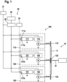
- FIG. 1 a parallel start system according to a preferred embodiment of the invention is shown schematically and designated overall by 100.
- the parallel start system 100 is connected to a network 20, for example an on-board network of a vehicle, and is used to start an internal combustion engine 10.
- the internal combustion engine 10 has a crankshaft 12 and a ring gear 11 connected to it in a rotationally fixed manner. To start the internal combustion engine, the ring gear 11 and thus the crankshaft 12 must be set in rotation until a rotational speed sufficient for ignition is reached.
- the network 20 is supplied, for example, by a battery 21, which in the present case supplies a computing unit 23 for controlling the parallel start system 100, for example an engine control unit, the parallel start system 100 and other electrical loads or consumers 24 via a fuse box 22.
- a computing unit 23 for controlling the parallel start system 100 for example an engine control unit, the parallel start system 100 and other electrical loads or consumers 24 via a fuse box 22.
- the parallel starter system 100 has a first starter 110 (master) and two further starters 120, 130 (slaves), each of which has a logic unit 111, 121, 131, a switching/alignment unit 112, 122, 132, a starter motor M and a pinion 113, 123, 133.
- the logic unit 111 of the first starter 110 has a first data interface 111a for communication with the computing unit 23 and a second data interface 111b for communication with the other starters 120, 130.
- the logic units 121, 131 of the other starters in turn each have a data interface 121b or 131b for communication with the logic unit 111 of the first starter.
- Communication between the starters takes place via a bidirectional interface, in particular a CAN interface.
- communication between the computing unit 23 and the logic unit 111 of the first starter also takes place via a bidirectional interface.
- the respective switching/engaging units 112, 122 and 132 of the starters have, on the one hand, an actuator for bringing the respective pinion 113, 123, 133 into the engaging position shown in the figure, in which the respective pinion is in engagement with the ring gear 11 of the internal combustion engine 10.
- the respective pinion can be moved horizontally in the figure along the double arrow to the right and to the left. In the starting position, the respective pinion is disengaged from the ring gear 11 and must first be brought into engagement with the ring gear 11 in order to start the combustion engine.
- the respective switching/engaging unit 112, 122, 132 has a switch, in particular a relay, for energizing the starter motor M.
- the respective switching/engaging unit is controlled by the associated logic unit.
- the method begins in a step 201 when a start request occurs in the network 20.
- a step 202 the start request is transmitted from the computing unit 23 to the first starter 110.
- a step 203 the start request is checked for plausibility by the logic unit 111 of the first starter 110, wherein, in particular in the event that the start request is considered to be inadmissible, an error message can be transmitted back to the computing unit 23, connection 204.
- the plausibility check may include at least one check selected from whether an immobilizer is active, whether the drive train is in a startable state, e.g. because the transmission and/or clutch are torque-decoupled and the combustion engine is at a standstill, whether the temperature of the starter is within a permissible range, and whether the on-board network voltage is within a permissible range.
- the logic unit 111 of the first starter 110 issues a lane-entry request to the logic units 121, 131 of the other starters in step 205.
- step 206 the logic units 111, 121, 131 control their respective shifting/engaging unit 112, 122, 132 to move the respective pinion 113, 123, 133 into the Figure 1 Furthermore, the logic units 121, 131 of the other starters are designed to output a meshing message after the associated pinion 123, 131 has been successfully brought into the meshing position, which is transmitted to the logic unit 111 of the first starter 110.
- step 207 the logic unit 111 of the first starter 110 monitors the respective alignment processes. If the logic unit 111 receives the alignment message from all other starters, it continues with step 208.
- step 209 it is checked whether a predetermined waiting time, for example since the lane-entry command was issued or since the start request was received, has already elapsed. If this is not the case, the system returns to step 207. However, if this is the case, the system continues with step 210.
- a predetermined waiting time for example since the lane-entry command was issued or since the start request was received
- the logic unit 111 of the first starter 110 issues a cranking request to the other starters at its interface 111b and controls its own switching/engaging unit 112 so that the starter motor M is supplied with the main current in order to crank the associated pinion.
- the logic units 121, 131 control the associated switching/engaging units 122, 132 in order to supply the respective starter motor M with the main current in order to crank the associated pinion.
- step 211 a regular start of the combustion engine takes place, whereas in step 212 an emergency start of the combustion engine takes place.
- the logic unit 111 of the first starter 110 issues a cranking request at its interface 111b in step 210 only to those other starters from which a lane-engagement message was received, for example in the form of addressed data.
- the starters with engagement signal are operated under increased specific load with a reduced permissible duty cycle in order to enable a start attempt even in the event of a fault. If a bidirectional interface to the on-board network 20 or to the computing unit 23 is used, this fault condition can be reported back to it in order to initiate a service procedure as soon as possible.
Landscapes
- Engineering & Computer Science (AREA)
- Chemical & Material Sciences (AREA)
- Combustion & Propulsion (AREA)
- Mechanical Engineering (AREA)
- General Engineering & Computer Science (AREA)
- Combined Controls Of Internal Combustion Engines (AREA)
Description
- Die vorliegende Erfindung betrifft eine Parallelstartanlage zum Starten eines Verbrennungsmotors.
- Zum Starten von Verbrennungsmotoren werden üblicherweise elektrisch betätigte Starter verwendet. Bei größeren Motoren mit mehreren Zehn oder Hundert Litern Hubraum, wie z.B. bei Baumaschinen, großen Traktoren, Stationärmotoren und auch Schiffsmotoren, ist es bekannt, mehrere Starter parallel zu schalten, um die hohe Starterleistung bereitstellen zu können. Bei diesen sog. Parallelstartanlagen wirken gleichzeitig mehrere Elektrostarter auf den Zahnkranz des Verbrennungsmotors und können somit gemeinsam die erforderliche Startleistung aufbringen.
- Um eine Überlastung der verwendeten Starter zu Beginn der Startphase zu vermeiden, können die Starter durch eine Reihenschaltung von Schaltkontakten synchronisiert werden. Zu Beginn des Startvorgangs werden die Einrückrelais aller Starter gleichzeitig angesteuert und diese beginnen mit dem Einspurvorgang der Ritzel in den Zahnkranz. Der Hauptstrom für alle Starter wird gleichzeitig erst nach dem Einspuren des letzten Einzelstarters geschaltet.
- Bei einer festen Reihenschaltung der Einzelkontakte führt eine Störung an einem einzelnen Starter oder an der Verkabelung zwischen den Startern jedoch zum Komplettausfall der Startanlage. Die Ausfallwahrscheinlichkeit des Gesamtsystems wird somit entsprechend der Anzahl der eingesetzten Starter erhöht. Werden die Erregerspulen der (Motorstrom-)Schaltrelais aller Einzelstarter gleichzeitig angesteuert, wird die Stromaufnahme im Ansteuerpfad und in dessen Schaltelement (z.B. im Motorsteuergerät) vervielfacht.
- Aus der
DE 10 2005 006 248 A1 ist eine Parallelstartanlage mit geringem Verdrahtungsaufwand bekannt. Diese umfasst mehrere parallelgeschaltete Starter, die jeweils einen Startermotor und ein Einrückrelais aufweisen. Diese Parallelstartanlage kann besonders einfach und kostengünstig realisiert werden, wenn mindestens einer der Schalter ein Leistungsrelais umfasst, das den Hauptstrompfad zum zugehörigen Startermotor schaltet, und das Einrückrelais, das Leistungsrelais und der Startermotor als bauliche Einheit realisiert sind. -
DE 10 2009 001 690 A1 betrifft eine Parallelstartanlage mit mehreren Startern und einer separaten Steuereinheit. -
DE 10 2010 030 398 A1 betrifft eine Parallelstartanlage, bei der in Abhängigkeit von definierten Betriebszuständen alle, ein Teil oder einzelne Startermotoren zum Starten der Brennkraftmaschine ansteuerbar sind. Zur Ansteuerung ist eine separate Startersteuerung vorhanden. -
EP 2 923 215 A1 betrifft eine Testeinheit zum Testen eines Dualstarters. Die Testeinheit weist zwei Schnittstellen zur Kommunikation mit entsprechenden Starterschnittstellen auf. - Erfindungsgemäß werden eine Parallelstartanlage zum Starten eines Verbrennungsmotors und ein Verfahren zum Betreiben einer solchen mit den Merkmalen der unabhängigen Patentansprüche vorgeschlagen. Vorteilhafte Ausgestaltungen sind Gegenstand der Unteransprüche sowie der nachfolgenden Beschreibung.
- Die Erfindung bedient sich der Maßnahme, das parallele Betreiben mehrerer Starter nicht mehr schaltungstechnisch, sondern informationstechnisch zu steuern. Dazu weist jeder der wenigstens zwei Starter der Parallelstartanlage eine Logikeinheit mit einer Datenschnittstelle auf, über welche die Logikeinheiten datenübertragend miteinander verbunden sind. Ein erster der Starter fungiert dann als Master, dessen Logikeinheit dazu eingerichtet ist, auf den Empfang einer Startanforderung hin, insbesondere von einer übergeordneten Recheneinheit wie z.B. dem Motorsteuergerät, eine Einspuranforderung und eine Durchdrehanforderung an die Logikeinheit mindestens eines weiteren Starters, der als Slave fungiert, auszugeben, wobei die Logikeinheit des mindestens einen weiteren Starters dazu eingerichtet ist, auf den Empfang der Einspuranforderung hin den mechanischen Aktor, insbesondere ein Einspurrelais, zum Verbringen des Ritzels in die Einspurposition anzusteuern und auf den Empfang der Durchdrehanforderung hin den Startermotor zum Durchdrehen des Ritzels anzusteuern. Wenngleich im Folgenden meist von einem bzw. dem weiteren Starter die Rede ist, gelten die beschriebenen Maßnahmen und Merkmale vorzugsweise für alle weiteren Starter bzw. Slaves der Parallelstartanlage.
- Aufgrund der informationstechnischen Parallelschaltung führt eine Störung an einem einzelnen Starter oder an der Verkabelung zwischen den Startern nicht zu einem Komplettausfall der Startanlage. Vielmehr ist eine flexible Ansteuerung der Mehrfachstartanlage auch bei Funktionsstörung eines Einzelstarters möglich. Das Bordnetz wird ansteuerseitig nicht mehr mit parallelgeschalteten Relais belastet, denn die informationstechnische Parallelschaltung belastet die übergeordnete Recheneinheit bzw. das Bordnetz mit einem Relaisspulenstrom, so dass die Stromaufnahme im Ansteuerpfad reduziert ist.. Somit kann dies entsprechend einer geringeren Ausgangsleistung dimensioniert werden.
- Darüber hinaus kann (je nach implementierter Betriebsstrategie) die Verfügbarkeit der Startanlage mittels begrenzter Redundanz sogar über diejenige eines Einzelstarters hinaus gesteigert werden, sofern ein entsprechendes "Notlaufkonzept" realisiert wird. Beispielsweise kann ein eingeschränkter "Notbetrieb" mit z.B. 2 von 3 Startern noch ermöglicht werden.
- Im Rahmen der Erfindung werden somit die einzelnen Starter einer Parallelstartanlage jeweils mit einer Logikeinheit (intelligenten Ansteuerelektronik) (insbesondere anstelle eines elektromechanischen Ansteuerrelais) ausgestattet, die sowohl den Einspurvorgang (Vorspurbewegung) auslösen als auch den Hauptstromschalter zum Bestromen des Startermotors betätigen kann.
- Die Bestimmung, welcher der Starter der erste Starter bzw. Master im Sinne der Erfindung ist, kann beispielsweise bereits nach der Herstellung oder erst am Einbauort beispielsweise durch entsprechende Verkabelung (der Master ist derjenige Starter, der (z.B. als einziger oder als erster) mit der übergeordneten Recheneinheit verbunden ist) oder Steckerkodierung oder entsprechende Konfiguration, sowohl hardware- (z.B. Jumper, DIP-Schalter) als auch softwaremäßig (sog. End-of-line-Programmierung) festgelegt werden.
- Zweckmäßigerweise ist die Logikeinheit des ersten der wenigstens zwei Starter dazu eingerichtet ist, auf den Empfang der Startanforderung hin den mechanischen Aktor zum Verbringen des Ritzels in die Einspurposition anzusteuern. Mit anderen Worten spurt also der Master nach Empfang der Startanforderung ebenfalls ein.
- Vorzugsweise ist die Logikeinheit des wenigstens einen weiteren Starters dazu eingerichtet, nach dem erfolgreichen Verbringen des Ritzels in die Einspurposition eine Einspurmeldung auszugeben. Auf diese Weise kann vom Master leicht überprüft werden, wann der Einspurvorgang des bzw. der Slaves abgeschlossen ist und ob bzw. welche Einspurvorgänge erfolgreich waren.
- Zweckmäßigerweise ist die Logikeinheit des ersten Starters dazu eingerichtet, auf den Empfang einer Einspurmeldung von der Logikeinheit des wenigstens einen weiteren Starters hin die Durchdrehanforderung auszugeben und/oder den eigenen Startermotor zum Durchdrehen des Ritzels anzusteuern. Mit anderen Worten sendet der Master nach erfolgreichem Einspuren aller Slaves (und vorzugsweise auch eigenem erfolgreichen Einspuren) den Befehl zum Schalten des Hauptstroms (Strom für Startermotor) an alle beteiligten Starter (und schaltet vorzugsweise auch den eigenen Hauptstrom), sodass der Durchdrehvorgang des Verbrennungsmotors synchronisiert beginnen kann.
- Gemäß einer bevorzugten Ausführungsform ist die Logikeinheit des ersten Starters dazu eingerichtet, nach Ablauf einer vorbestimmten Zeitspanne nach dem Ausgeben der Einspuranforderung die Durchdrehanforderung auszugeben und/oder den Startermotor zum Durchdrehen des Ritzels anzusteuern. Dies erlaubt insbesondere das Starten des Verbrennungsmotors auch dann, wenn nicht alle Einspurvorgänge erfolgreich abgeschlossen werden konnten, z.B. wegen einer sog. Zahn-auf-Zahn-Stellung zwischen Ritzel und Zahnkranz o.ä. Mit anderen Worten sendet der Master auch nach Zeitablauf den Befehl zum Schalten des Hauptstroms (Strom für Startermotor) an alle oder nur an die eingespurten Starter (und schaltet vorzugsweise auch den eigenen Hauptstrom), sodass der Durchdrehvorgang des Verbrennungsmotors synchronisiert beginnen kann. Diese zweite Alternative umfasst, dass die Logikeinheit des ersten Starters dazu eingerichtet ist, nach Ablauf der vorbestimmten Zeitspanne nach dem Ausgeben der Einspuranforderung die Durchdrehanforderung nur an die Logikeinheit der weiteren Starter auszugeben, von der sie eine Einspurmeldung erhalten hat.
- Vorteilhafterweise weist die Logikeinheit des ersten Starters eine einzige Datenschnittstelle zum Empfangen der Startanforderung, zum Ausgeben der Einspuranforderung, zum Ausgeben der Durchdrehanforderung und zum Empfangen der Einspurmeldung auf. Diese Datenschnittstelle ist somit bidirektional. Eine solche Ausführungsform kommt mit wenigen zusätzlichen Bauteilen aus.
- Alternativ kann jedoch vorgesehen sein, dass die Logikeinheit des ersten Starters eine erste Datenschnittstelle zum Empfangen der Startanforderung und eine zweite Datenschnittstelle zum Ausgeben der Einspuranforderung und der Durchdrehanforderung und zum Empfangen der Einspurmeldung aufweist. Mit anderen Worten dient die erste Datenschnittstelle zur Kommunikation mit der übergeordneten Recheneinheit und die zweite Datenschnittstelle zur Kommunikation unter den Startern. Die erste Datenschnittstelle muss zumindest unidirektional sein, um die Startanforderung an den ersten Starter übertragen zu können. Die zweite Datenschnittstelle muss bidirektional sein, um die Einspuranforderung, Durchdrehanforderung und Einspurmeldung übertragen zu können.
- Erfindungsgemäß ist die Datenschnittstelle eine Bus-Schnittstelle, insbesondere CAN, FlexRay oder LIN. Damit können erprobte Schnittstellen Verwendung finden.
- Weitere Vorteile und Ausgestaltungen der Erfindung ergeben sich aus der Beschreibung und der beiliegenden Zeichnung.
- Die Erfindung ist anhand von Ausführungsbeispielen in der Zeichnung schematisch dargestellt und wird im Folgenden unter Bezugnahme auf die Zeichnung beschrieben.
-
- .Figur 1
- zeigt schematisch eine Parallelstartanlage gemäß einer bevorzugten Ausführungsform der Erfindung.
- Figur 2
- zeigt schematisch eine bevorzugte Ausführungsform eines Startverfahrens unter Einsatz einer Parallelstartanlage gemäß
Figur 1 . - In
Figur 1 ist eine Parallelstartanlage gemäß einer bevorzugten Ausführungsform der Erfindung schematisch dargestellt und insgesamt mit 100 bezeichnet. - Die Parallelstartanlage 100 ist mit einem Netz 20, beispielsweise einem Bordnetz eines Fahrzeugs, verbunden und dient zum Starten eines Verbrennungsmotors 10. Der Verbrennungsmotor 10 weist eine Kurbelwelle 12 und einen mit dieser drehdrehfest verbundenen Zahnkranz 11 auf. Zum Starten des Verbrennungsmotors müssen der Zahnkranz 11 und damit die Kurbelwelle 12 in Rotation versetzt werden, bis eine für das Zünden ausreichende Drehgeschwindigkeit erreicht ist.
- Das Netz 20 wird beispielsweise von einer Batterie 21 versorgt, welche vorliegend über einen Sicherungskasten 22 eine Recheneinheit 23 zur Ansteuerung der Parallelstartanlage 100, beispielsweise ein Motorsteuergerät, die Parallelstartanlage 100 und sonstige elektrische Lasten bzw. Verbraucher 24 versorgt.
- Die Parallelstartanlage 100 weist einen ersten Starter 110 (Master) und zwei weitere Starter 120, 130 (Slaves) auf, die jeweils eine Logikeinheit 111, 121, 131, eine Schalt-/Einspureinheit 112, 122, 132, einen Startermotor M und ein Ritzel 113, 123, 133 aufweisen.
- Die Logikeinheit 111 des ersten Starters 110 weist eine erste Datenschnittstelle 111a zur Kommunikation mit der Recheneinheit 23 und eine zweite Datenschnittstelle 111b zur Kommunikation mit den weiteren Startern 120, 130 auf. Die Logikeinheiten 121, 131 der weiteren Starter wiederum weisen jeweils eine Datenschnittstelle 121 b bzw. 131b zur Kommunikation mit der Logikeinheit 111 des ersten Starters auf. Die Kommunikation unter den Startern erfolgt über eine bidirektionale Schnittstelle, insbesondere eine CAN-Schnittstelle. Beispielhaft erfolgt auch die Kommunikation zwischen der Recheneinheit 23 und der Logikeinheit 111 des ersten Starters über eine bi-direktionale Schnittstelle.
- Die jeweiligen Schalt-/Einspureinheiten 112, 122 und 132 der Starter weisen zum einen einen Aktor zum Verbringen des jeweiligen Ritzels 113, 123, 133 in die in der Figur gezeigte Einspurposition, in welcher das jeweilige Ritzel in Eingriff mit dem Zahnkranz 11 des Verbrennungsmotors 10 steht, auf. Dazu kann das jeweilige Ritzel in der Figur waagerecht entlang des Doppelpfeils nach rechts und nach links verschoben werden. In der Ausgangsposition befindet sich das jeweilige Ritzel außer Eingriff mit dem Zahnkranz 11 und muss zum Starten des Verbrennungsmotors zunächst in Eingriff mit dem Zahnkranz 11 gebracht werden.
- Weiterhin weist die jeweilige Schalt-/Einspureinheit 112, 122, 132 einen Schalter, insbesondere ein Relais, zum Bestromen des Startermotors M auf. Die jeweilige Schalt-/Einspureinheit wird von der zugehörigen Logikeinheit angesteuert.
- Ein beispielhaftes Verfahren gemäß einer bevorzugten Ausführungsform der Erfindung soll im Folgenden unter Bezugnahme auf
Figur 2 erläutert werden. - Das Verfahren beginnt in einem Schritt 201, wenn eine Startanforderung im Netz 20 auftritt.
- In einem Schritt 202 wird die Startanforderung von der Recheneinheit 23 an den ersten Starter 110 übermittelt.
- In einem Schritt 203 wird die Startanforderung von der Logikeinheit 111 des ersten Starters 110 plausibilisiert, wobei insbesondere für den Fall, dass die Startanforderung als unzulässig angesehen wird, eine Fehlernachricht an die Recheneinheit 23 zurück übertragen werden kann, Verbindung 204.
- Beispielsweise kann die Plausibilisierung wenigstens eine Prüfung umfassen ausgewählt aus ob eine Wegfahrsperre aktiv ist, ob sich der Triebstrang in einem startfähigen Zustand befindet, z.B. weil Getriebe und/oder Kupplung drehmomententkoppelt sind und der Verbrennungsmotor stillsteht, ob sich die Temperatur des Starters in einem zulässigen Bereich befindet, und ob sich die Bordnetzspannung in einem zulässigen Bereich befindet.
- Wird die Startanforderung in Schritt 203 jedoch als zulässig erkannt, gibt die Logikeinheit 111 des ersten Starters 110 in Schritt 205 eine Einspuranforderung an die Logikeinheiten 121, 131 der weiteren Starter aus.
- In Schritt 206 steuern die Logikeinheiten 111, 121, 131 ihre jeweilige Schalt-/Einspureinheit 112, 122, 132 an, um das jeweilige Ritzel 113, 123, 133 in die in
Figur 1 gezeigte Einspurposition zu verbringen. Weiterhin sind die Logikeinheiten 121, 131 der weiteren Starter dazu eingerichtet, nach dem erfolgreichen Verbringen des zugehörigen Ritzels 123, 131 in die Einspurposition eine Einspurmeldung auszugeben, welche an die Logikeinheit 111 des ersten Starters 110 übertragen werden. - In einem Schritt 207 überwacht die Logikeinheit 111 des ersten Starters 110 die jeweiligen Einspurvorgänge. Erhält die Logikeinheit 111 von allen weiteren Startern die Einspurmeldung, wird mit Schritt 208 fortgefahren.
- Wenn die Logikeinheit 111 noch nicht alle Einspurmeldungen erhalten hat, wird mit Schritt 209 fortgefahren.
- In Schritt 209 wird überprüft, ob eine vorgegebene Wartezeit, beispielsweise seit dem Ausgeben des Einspurbefehls oder seit dem Empfangen der Startanforderung, bereits abgelaufen ist. Ist dies nicht der Fall, wird zu Schritt 207 zurückgekehrt. Ist dies jedoch der Fall, wird mit Schritt 210 fortgefahren.
- Sowohl in Schritt 208 als auch in Schritt 210 gibt die Logikeinheit 111 des ersten Starters 110 an ihrer Schnittstelle 111b eine Durchdrehanforderung an die weiteren Starter aus und steuert ihre eigene Schalt-/Einspureinheit 112 so an, dass der Startermotor M mit dem Hauptstrom versorgt wird, um das zugehörige Ritzel durchzudrehen. Nach Empfang der Durchdrehanforderung steuern die Logikeinheiten 121, 131 die zugehörigen Schalt-/Einspureinheiten 122, 132 an, um den jeweiligen Startermotor M mit Hauptstrom zu versorgen, um das zugehörige Ritzel durchzudrehen.
- Somit erfolgt in Schritt 211 ein regulärer Start des Verbrennungsmotors, wohingegen in Schritt 212 ein Notstart des Verbrennungsmotors erfolgt. Es kann in diesem Zusammenhang vorgesehen sein, dass die Logikeinheit 111 des ersten Starters 110 in Schritt 210 an ihrer Schnittstelle 111b eine Durchdrehanforderung nur an diejenigen weiteren Starter ausgibt, von denen eine Einspurmeldung empfangen wurde, beispielsweise in Form von adressierten Daten.
- Bei einem solchen Notstart ist dann vorzugsweise vorgesehen, dass die Starter mit Einspurmeldung unter erhöhter spezifischer Belastung mit reduzierter zulässiger Einschaltdauer betrieben werden, um auch im Fehlerfall einen Startversuch zu ermöglichen. Sofern eine bidirektionale Schnittstelle zum Bordnetz 20 bzw. zur Recheneinheit 23 eingesetzt wird, kann dieser Fehlerzustand dorthin zurückgemeldet werden, um baldmöglich einen Servicevorgang zu veranlassen.
Claims (11)
- Parallelstartanlage (100) zum Starten eines Verbrennungsmotors (10), aufweisend wenigstens zwei Starter (110, 120, 130),wobei jeder der wenigstens zwei Starter (110, 120, 130)ein Ritzel (113, 123, 133) zum Eingreifen in einen Zahnkranz (11) des zu startenden Verbrennungsmotors (10),einen Startermotor (M) zum Durchdrehen des Ritzels (113, 123, 133), einen mechanischen Aktor (112, 122, 132) zum Verbringen des Ritzels (113, 123, 133) in eine Einspurposition undeine Logikeinheit (111, 121, 131) mit einer Datenschnittstelle (111a, 111b, 121b, 131b) aufweist,wobei die Logikeinheit (111, 121, 131) dazu eingerichtet ist,den mechanischen Aktor (112, 122, 132) zum Verbringen des Ritzels (113, 123, 133) in die Einspurposition anzusteuern undden Startermotor (M) zum Durchdrehen des Ritzels (113, 123, 133) anzusteuern,wobei die Logikeinheit (111) eines ersten der wenigstens zwei Starter (110, 120, 130) dazu eingerichtet ist, auf den Empfang einer Startanforderung hin eine Einspuranforderung und eine Durchdrehanforderung auszugeben,wobei die Logikeinheit (121, 131) wenigstens eines weiteren der wenigstens zwei Starter (110, 120, 130) dazu eingerichtet ist, auf den Empfang der Einspuranforderung hin den mechanischen Aktor (112, 122, 132) zum Verbringen des Ritzels (113, 123, 133) in die Einspurposition anzusteuern und auf den Empfang der Durchdrehanforderung hin den Startermotor (M) zum Durchdrehen des Ritzels (113, 123, 133) anzusteuern,dadurch gekennzeichnet,dass die Datenschnittstelle (111a, 111b, 121b, 131b) eine Bus-Schnittstelle ist.
- Parallelstartanlage (100) nach Anspruch 1, wobei die Logikeinheit (121, 131) des wenigstens einen weiteren der wenigstens zwei Starter (110, 120, 130) dazu eingerichtet ist, nach dem erfolgreichen Verbringen des Ritzels (113, 123, 133) in die Einspurposition eine Einspurmeldung auszugeben.
- Parallelstartanlage (100) nach Anspruch 2, wobei die Logikeinheit (111) des ersten der wenigstens zwei Starter (110, 120, 130) dazu eingerichtet ist, auf den Empfang einer Einspurmeldung von der Logikeinheit (121, 131) des wenigstens einen weiteren der wenigstens zwei Starter (110, 120, 130) hin die Durchdrehanforderung auszugeben und/oder den Startermotor (M) zum Durchdrehen des Ritzels (113) anzusteuern.
- Parallelstartanlage (100) nach einem der vorstehenden Ansprüche, wobei die Logikeinheit (111) des ersten der wenigstens zwei Starter (110, 120, 130) dazu eingerichtet ist, nach Ablauf einer vorbestimmten Zeitspanne nach dem Ausgeben der Einspuranforderung die Durchdrehanforderung auszugeben und/oder den Startermotor (M) zum Durchdrehen des Ritzels (113) anzusteuern.
- Parallelstartanlage (100) nach Anspruch 3 und 4, wobei die Logikeinheit (111) des ersten der wenigstens zwei Starter (110, 120, 130) dazu eingerichtet ist, nach Ablauf der vorbestimmten Zeitspanne nach dem Ausgeben der Einspuranforderung die Durchdrehanforderung an die Logikeinheit (121, 131) des wenigstens einen weiteren der wenigstens zwei Starter (110, 120, 130) auszugeben, von der sie eine Einspurmeldung erhalten hat.
- Parallelstartanlage (100) nach einem der vorstehenden Ansprüche, wobei die Logikeinheit (111) des ersten der wenigstens zwei Starter (110, 120, 130) dazu eingerichtet ist, auf den Empfang der Startanforderung hin den mechanischen Aktor zum Verbringen des Ritzels (113) in die Einspurposition anzusteuern.
- Parallelstartanlage (100) nach einem der vorstehenden Ansprüche, wobei die Logikeinheit (111) des ersten der wenigstens zwei Starter (110, 120, 130) eine einzige Datenschnittstelle zum Empfangen der Startanforderung, zum Ausgeben der Einspuranforderung, zum Ausgeben der Durchdrehanforderung und zum Empfangen der Einspurmeldung aufweist.
- Parallelstartanlage (100) nach einem der Ansprüche 1 bis 6, wobei die Logikeinheit (111) des ersten der wenigstens zwei Starter (110, 120, 130) eine erste Datenschnittstelle (111a) zum Empfangen der Startanforderung und eine zweite Datenschnittstelle (111b) zum Ausgeben der Einspuranforderung und der Durchdrehanforderung und zum Empfangen der Einspurmeldung aufweist.
- Parallelstartanlage (100) nach einem der vorstehenden Ansprüche, wobei die Logikeinheit (121, 131) des wenigstens einen weiteren der wenigstens zwei Starter (110, 120, 130) eine Datenschnittstelle zum Empfangen der Einspuranforderung und der Durchdrehanforderung und zum Ausgeben der Einspurmeldung aufweist.
- Anordnung aus einem Verbrennungsmotor (10) und einer Parallelstartanlage (100) nach einem der vorstehenden Ansprüche.
- Anordnung aus einer Recheneinheit (23), die dazu eingerichtet ist, eine Startanforderung auszugeben, und einer Parallelstartanlage (100) nach einem der Ansprüche 1 bis 9.
Applications Claiming Priority (1)
| Application Number | Priority Date | Filing Date | Title |
|---|---|---|---|
| DE102019109496.8A DE102019109496A1 (de) | 2019-04-10 | 2019-04-10 | Parallelstartanlage zum Starten eines Verbrennungsmotors |
Publications (2)
| Publication Number | Publication Date |
|---|---|
| EP3722591A1 EP3722591A1 (de) | 2020-10-14 |
| EP3722591B1 true EP3722591B1 (de) | 2024-12-18 |
Family
ID=70165812
Family Applications (1)
| Application Number | Title | Priority Date | Filing Date |
|---|---|---|---|
| EP20167701.0A Active EP3722591B1 (de) | 2019-04-10 | 2020-04-02 | Parallelstartanlage zum starten eines verbrennungsmotors |
Country Status (3)
| Country | Link |
|---|---|
| EP (1) | EP3722591B1 (de) |
| CN (1) | CN111810337B (de) |
| DE (1) | DE102019109496A1 (de) |
Citations (3)
| Publication number | Priority date | Publication date | Assignee | Title |
|---|---|---|---|---|
| US6694938B2 (en) * | 2001-01-31 | 2004-02-24 | Valeo Equipements Electriques Moteur | Method of controlling a starter system for a heat engine, of the type having two starters, and apparatus for performing the method |
| DE102005006248A1 (de) * | 2005-02-11 | 2006-08-17 | Robert Bosch Gmbh | Parallelstartanlage mit geringem Verdrahtungsaufwand |
| US20140117992A1 (en) * | 2012-10-29 | 2014-05-01 | Tognum America Inc. | Starter Motor Testing Device |
Family Cites Families (5)
| Publication number | Priority date | Publication date | Assignee | Title |
|---|---|---|---|---|
| DE102008004381A1 (de) * | 2008-01-15 | 2009-07-16 | Robert Bosch Gmbh | Parallelstartanlage |
| DE102009001690A1 (de) * | 2009-03-20 | 2010-09-23 | Robert Bosch Gmbh | Steuerung für parallel anordenbare Starter, Schaltungsanordnung, Verfahren und Computerprogrammprodukt |
| DE102009029993B4 (de) * | 2009-06-23 | 2020-08-06 | Bayerische Motoren Werke Aktiengesellschaft | Vorrichtung und Verfahren zum Starten eines Verbrennungsmotors |
| DE102010030398A1 (de) * | 2010-06-23 | 2011-12-29 | Robert Bosch Gmbh | Startvorrichtung, Startsystem, Verfahren zum Betreiben einer Startvorrichtung und Computerprogrammprodukt |
| DE102012205746A1 (de) * | 2012-04-10 | 2013-10-10 | Robert Bosch Gmbh | Kraftfahrzeugstarteranordnung, Schaltrelaisstecker, Start-Stopp-System und Kraftfahrzeug-Startverfahren |
-
2019
- 2019-04-10 DE DE102019109496.8A patent/DE102019109496A1/de active Pending
-
2020
- 2020-04-02 EP EP20167701.0A patent/EP3722591B1/de active Active
- 2020-04-08 CN CN202010270481.3A patent/CN111810337B/zh active Active
Patent Citations (4)
| Publication number | Priority date | Publication date | Assignee | Title |
|---|---|---|---|---|
| US6694938B2 (en) * | 2001-01-31 | 2004-02-24 | Valeo Equipements Electriques Moteur | Method of controlling a starter system for a heat engine, of the type having two starters, and apparatus for performing the method |
| DE102005006248A1 (de) * | 2005-02-11 | 2006-08-17 | Robert Bosch Gmbh | Parallelstartanlage mit geringem Verdrahtungsaufwand |
| US20140117992A1 (en) * | 2012-10-29 | 2014-05-01 | Tognum America Inc. | Starter Motor Testing Device |
| EP2923215B1 (de) * | 2012-10-29 | 2020-02-12 | MTU America Inc. | Prüfvorrichtung für anlassers |
Also Published As
| Publication number | Publication date |
|---|---|
| DE102019109496A1 (de) | 2020-10-15 |
| CN111810337B (zh) | 2023-11-28 |
| EP3722591A1 (de) | 2020-10-14 |
| CN111810337A (zh) | 2020-10-23 |
Similar Documents
| Publication | Publication Date | Title |
|---|---|---|
| EP0848159B1 (de) | Startvorrichtung zum Starten einer Brennkraftmaschine | |
| EP2585708B1 (de) | Startvorrichtung und startverfahren einer brennkraftmaschine mit mehrfachen startermotoren | |
| DE102009028294A1 (de) | Vorrichtung zum Starten einer Verbrennungskraftmaschine | |
| DE102005004326A1 (de) | Startvorrichtung für einen Verbrennungsmotor mit separatem Einrück- und Startvorgang | |
| EP3247613B1 (de) | Lenksystem für ein automatisiertes fahren eines kraftfahrzeuges | |
| EP2245297B1 (de) | Parallelstartanlage | |
| EP2354532B1 (de) | Parallel-Schalteranordnung | |
| WO2015180886A1 (de) | Verfahren und vorrichtung zur übergabe eines kraftfahrzeugs an den fahrer bei einem automatischen ausparkvorgang | |
| DE102009054765A1 (de) | Elektronische Steuereinheit für einen Motor | |
| DE102010062238A1 (de) | Startvorrichtung, Schnittstelleneinrichtung und Verfahren zum Betreiben eines Systems einer Startvorrichtung | |
| DE102011081093A1 (de) | Startsystem, Verfahren und Computerprogrammprodukt zum Starten einer Brennkraftmaschine | |
| EP3722591B1 (de) | Parallelstartanlage zum starten eines verbrennungsmotors | |
| DE112014000754T5 (de) | Starter- und Schaltsystem mit variablem Fluss | |
| DE102006027702B4 (de) | Maschinenstartsystem mit zwei Anlassern eines unterschiedlichen Typs | |
| DE102017219844B4 (de) | Motorstartvorrichtung | |
| DE19721386A1 (de) | Startvorrichtung zum Starten einer Brennkraftmaschine | |
| DE19841659B4 (de) | Verfahren zur Steuerung einer Kraftstoffpumpe für ein Kraftfahrzeug | |
| WO2012110394A2 (de) | Verfahren eines startsystems, startsystem, schaltungsanordnung und computerprogrammprodukt | |
| WO2010105902A1 (de) | Steuerung für parallel anordenbare starter, schaltungsanordnunq, verfahren und computerprogrammprodukt | |
| DE102011002157A1 (de) | Anlasseransteuervorrichtung | |
| DE102015212623A1 (de) | Verfahren zum Betrieb parallel geschalteter Generatoreinheiten | |
| EP2146088B1 (de) | Verfahren zum Betreiben eines Motors eines Kraftfahrzeugs sowie Kraftfahrzeug | |
| DE102009001350A1 (de) | Verfahren und Vorrichtung zum Betreiben einer Brennkraftmaschine eines Kraftfahrzeugs | |
| DE102011000850A1 (de) | System zum Ankurbeln einer Verbrennungsmaschine durch Ineingriffbringen eines Ritzels mit einem Außenzahnkranz | |
| DE102008043544A1 (de) | Startersteuerung, Startersystem, Verfahren für dieselben, Computerprogrammprodukt |
Legal Events
| Date | Code | Title | Description |
|---|---|---|---|
| PUAI | Public reference made under article 153(3) epc to a published international application that has entered the european phase |
Free format text: ORIGINAL CODE: 0009012 |
|
| STAA | Information on the status of an ep patent application or granted ep patent |
Free format text: STATUS: THE APPLICATION HAS BEEN PUBLISHED |
|
| AK | Designated contracting states |
Kind code of ref document: A1 Designated state(s): AL AT BE BG CH CY CZ DE DK EE ES FI FR GB GR HR HU IE IS IT LI LT LU LV MC MK MT NL NO PL PT RO RS SE SI SK SM TR |
|
| AX | Request for extension of the european patent |
Extension state: BA ME |
|
| STAA | Information on the status of an ep patent application or granted ep patent |
Free format text: STATUS: REQUEST FOR EXAMINATION WAS MADE |
|
| 17P | Request for examination filed |
Effective date: 20210414 |
|
| RBV | Designated contracting states (corrected) |
Designated state(s): AL AT BE BG CH CY CZ DE DK EE ES FI FR GB GR HR HU IE IS IT LI LT LU LV MC MK MT NL NO PL PT RO RS SE SI SK SM TR |
|
| STAA | Information on the status of an ep patent application or granted ep patent |
Free format text: STATUS: EXAMINATION IS IN PROGRESS |
|
| 17Q | First examination report despatched |
Effective date: 20221018 |
|
| RIC1 | Information provided on ipc code assigned before grant |
Ipc: F02D 41/28 20060101ALN20240507BHEP Ipc: F02N 15/06 20060101ALN20240507BHEP Ipc: F02N 11/08 20060101ALI20240507BHEP Ipc: F02N 11/00 20060101AFI20240507BHEP |
|
| GRAP | Despatch of communication of intention to grant a patent |
Free format text: ORIGINAL CODE: EPIDOSNIGR1 |
|
| STAA | Information on the status of an ep patent application or granted ep patent |
Free format text: STATUS: GRANT OF PATENT IS INTENDED |
|
| INTG | Intention to grant announced |
Effective date: 20240716 |
|
| GRAS | Grant fee paid |
Free format text: ORIGINAL CODE: EPIDOSNIGR3 |
|
| GRAA | (expected) grant |
Free format text: ORIGINAL CODE: 0009210 |
|
| STAA | Information on the status of an ep patent application or granted ep patent |
Free format text: STATUS: THE PATENT HAS BEEN GRANTED |
|
| AK | Designated contracting states |
Kind code of ref document: B1 Designated state(s): AL AT BE BG CH CY CZ DE DK EE ES FI FR GB GR HR HU IE IS IT LI LT LU LV MC MK MT NL NO PL PT RO RS SE SI SK SM TR |
|
| REG | Reference to a national code |
Ref country code: CH Ref legal event code: EP |
|
| REG | Reference to a national code |
Ref country code: DE Ref legal event code: R096 Ref document number: 502020009976 Country of ref document: DE |
|
| REG | Reference to a national code |
Ref country code: IE Ref legal event code: FG4D Free format text: LANGUAGE OF EP DOCUMENT: GERMAN |
|
| REG | Reference to a national code |
Ref country code: LT Ref legal event code: MG9D |
|
| PG25 | Lapsed in a contracting state [announced via postgrant information from national office to epo] |
Ref country code: HR Free format text: LAPSE BECAUSE OF FAILURE TO SUBMIT A TRANSLATION OF THE DESCRIPTION OR TO PAY THE FEE WITHIN THE PRESCRIBED TIME-LIMIT Effective date: 20241218 |
|
| PG25 | Lapsed in a contracting state [announced via postgrant information from national office to epo] |
Ref country code: FI Free format text: LAPSE BECAUSE OF FAILURE TO SUBMIT A TRANSLATION OF THE DESCRIPTION OR TO PAY THE FEE WITHIN THE PRESCRIBED TIME-LIMIT Effective date: 20241218 |
|
| PG25 | Lapsed in a contracting state [announced via postgrant information from national office to epo] |
Ref country code: BG Free format text: LAPSE BECAUSE OF FAILURE TO SUBMIT A TRANSLATION OF THE DESCRIPTION OR TO PAY THE FEE WITHIN THE PRESCRIBED TIME-LIMIT Effective date: 20241218 |
|
| PG25 | Lapsed in a contracting state [announced via postgrant information from national office to epo] |
Ref country code: NO Free format text: LAPSE BECAUSE OF FAILURE TO SUBMIT A TRANSLATION OF THE DESCRIPTION OR TO PAY THE FEE WITHIN THE PRESCRIBED TIME-LIMIT Effective date: 20250318 |
|
| REG | Reference to a national code |
Ref country code: NL Ref legal event code: MP Effective date: 20241218 |
|
| PG25 | Lapsed in a contracting state [announced via postgrant information from national office to epo] |
Ref country code: GR Free format text: LAPSE BECAUSE OF FAILURE TO SUBMIT A TRANSLATION OF THE DESCRIPTION OR TO PAY THE FEE WITHIN THE PRESCRIBED TIME-LIMIT Effective date: 20250319 Ref country code: LV Free format text: LAPSE BECAUSE OF FAILURE TO SUBMIT A TRANSLATION OF THE DESCRIPTION OR TO PAY THE FEE WITHIN THE PRESCRIBED TIME-LIMIT Effective date: 20241218 |
|
| PG25 | Lapsed in a contracting state [announced via postgrant information from national office to epo] |
Ref country code: RS Free format text: LAPSE BECAUSE OF FAILURE TO SUBMIT A TRANSLATION OF THE DESCRIPTION OR TO PAY THE FEE WITHIN THE PRESCRIBED TIME-LIMIT Effective date: 20250318 |
|
| PG25 | Lapsed in a contracting state [announced via postgrant information from national office to epo] |
Ref country code: NL Free format text: LAPSE BECAUSE OF FAILURE TO SUBMIT A TRANSLATION OF THE DESCRIPTION OR TO PAY THE FEE WITHIN THE PRESCRIBED TIME-LIMIT Effective date: 20241218 |
|
| PG25 | Lapsed in a contracting state [announced via postgrant information from national office to epo] |
Ref country code: SM Free format text: LAPSE BECAUSE OF FAILURE TO SUBMIT A TRANSLATION OF THE DESCRIPTION OR TO PAY THE FEE WITHIN THE PRESCRIBED TIME-LIMIT Effective date: 20241218 |
|
| PG25 | Lapsed in a contracting state [announced via postgrant information from national office to epo] |
Ref country code: PL Free format text: LAPSE BECAUSE OF FAILURE TO SUBMIT A TRANSLATION OF THE DESCRIPTION OR TO PAY THE FEE WITHIN THE PRESCRIBED TIME-LIMIT Effective date: 20241218 |
|
| PGFP | Annual fee paid to national office [announced via postgrant information from national office to epo] |
Ref country code: DE Payment date: 20250423 Year of fee payment: 6 |
|
| PG25 | Lapsed in a contracting state [announced via postgrant information from national office to epo] |
Ref country code: ES Free format text: LAPSE BECAUSE OF FAILURE TO SUBMIT A TRANSLATION OF THE DESCRIPTION OR TO PAY THE FEE WITHIN THE PRESCRIBED TIME-LIMIT Effective date: 20241218 |
|
| PG25 | Lapsed in a contracting state [announced via postgrant information from national office to epo] |
Ref country code: IS Free format text: LAPSE BECAUSE OF FAILURE TO SUBMIT A TRANSLATION OF THE DESCRIPTION OR TO PAY THE FEE WITHIN THE PRESCRIBED TIME-LIMIT Effective date: 20250418 |
|
| PG25 | Lapsed in a contracting state [announced via postgrant information from national office to epo] |
Ref country code: PT Free format text: LAPSE BECAUSE OF FAILURE TO SUBMIT A TRANSLATION OF THE DESCRIPTION OR TO PAY THE FEE WITHIN THE PRESCRIBED TIME-LIMIT Effective date: 20250421 |
|
| PG25 | Lapsed in a contracting state [announced via postgrant information from national office to epo] |
Ref country code: EE Free format text: LAPSE BECAUSE OF FAILURE TO SUBMIT A TRANSLATION OF THE DESCRIPTION OR TO PAY THE FEE WITHIN THE PRESCRIBED TIME-LIMIT Effective date: 20241218 |
|
| PG25 | Lapsed in a contracting state [announced via postgrant information from national office to epo] |
Ref country code: RO Free format text: LAPSE BECAUSE OF FAILURE TO SUBMIT A TRANSLATION OF THE DESCRIPTION OR TO PAY THE FEE WITHIN THE PRESCRIBED TIME-LIMIT Effective date: 20241218 |
|
| PG25 | Lapsed in a contracting state [announced via postgrant information from national office to epo] |
Ref country code: SK Free format text: LAPSE BECAUSE OF FAILURE TO SUBMIT A TRANSLATION OF THE DESCRIPTION OR TO PAY THE FEE WITHIN THE PRESCRIBED TIME-LIMIT Effective date: 20241218 |
|
| PG25 | Lapsed in a contracting state [announced via postgrant information from national office to epo] |
Ref country code: CZ Free format text: LAPSE BECAUSE OF FAILURE TO SUBMIT A TRANSLATION OF THE DESCRIPTION OR TO PAY THE FEE WITHIN THE PRESCRIBED TIME-LIMIT Effective date: 20241218 |
|
| PG25 | Lapsed in a contracting state [announced via postgrant information from national office to epo] |
Ref country code: IT Free format text: LAPSE BECAUSE OF FAILURE TO SUBMIT A TRANSLATION OF THE DESCRIPTION OR TO PAY THE FEE WITHIN THE PRESCRIBED TIME-LIMIT Effective date: 20241218 |
|
| PG25 | Lapsed in a contracting state [announced via postgrant information from national office to epo] |
Ref country code: SE Free format text: LAPSE BECAUSE OF FAILURE TO SUBMIT A TRANSLATION OF THE DESCRIPTION OR TO PAY THE FEE WITHIN THE PRESCRIBED TIME-LIMIT Effective date: 20241218 |
|
| REG | Reference to a national code |
Ref country code: DE Ref legal event code: R097 Ref document number: 502020009976 Country of ref document: DE |
|
| PG25 | Lapsed in a contracting state [announced via postgrant information from national office to epo] |
Ref country code: DK Free format text: LAPSE BECAUSE OF FAILURE TO SUBMIT A TRANSLATION OF THE DESCRIPTION OR TO PAY THE FEE WITHIN THE PRESCRIBED TIME-LIMIT Effective date: 20241218 |
|
| PLBE | No opposition filed within time limit |
Free format text: ORIGINAL CODE: 0009261 |
|
| STAA | Information on the status of an ep patent application or granted ep patent |
Free format text: STATUS: NO OPPOSITION FILED WITHIN TIME LIMIT |
|
| REG | Reference to a national code |
Ref country code: CH Ref legal event code: L10 Free format text: ST27 STATUS EVENT CODE: U-0-0-L10-L00 (AS PROVIDED BY THE NATIONAL OFFICE) Effective date: 20251029 |
|
| REG | Reference to a national code |
Ref country code: CH Ref legal event code: H13 Free format text: ST27 STATUS EVENT CODE: U-0-0-H10-H13 (AS PROVIDED BY THE NATIONAL OFFICE) Effective date: 20251125 |
|
| 26N | No opposition filed |
Effective date: 20250919 |
|
| PG25 | Lapsed in a contracting state [announced via postgrant information from national office to epo] |
Ref country code: LU Free format text: LAPSE BECAUSE OF NON-PAYMENT OF DUE FEES Effective date: 20250402 |
|
| PG25 | Lapsed in a contracting state [announced via postgrant information from national office to epo] |
Ref country code: MC Free format text: LAPSE BECAUSE OF FAILURE TO SUBMIT A TRANSLATION OF THE DESCRIPTION OR TO PAY THE FEE WITHIN THE PRESCRIBED TIME-LIMIT Effective date: 20241218 |
|
| GBPC | Gb: european patent ceased through non-payment of renewal fee |
Effective date: 20250402 |
|
| REG | Reference to a national code |
Ref country code: BE Ref legal event code: MM Effective date: 20250430 |
|
| PG25 | Lapsed in a contracting state [announced via postgrant information from national office to epo] |
Ref country code: GB Free format text: LAPSE BECAUSE OF NON-PAYMENT OF DUE FEES Effective date: 20250402 |
|
| PG25 | Lapsed in a contracting state [announced via postgrant information from national office to epo] |
Ref country code: FR Free format text: LAPSE BECAUSE OF NON-PAYMENT OF DUE FEES Effective date: 20250430 |
|
| PG25 | Lapsed in a contracting state [announced via postgrant information from national office to epo] |
Ref country code: BE Free format text: LAPSE BECAUSE OF NON-PAYMENT OF DUE FEES Effective date: 20250430 |
|
| PG25 | Lapsed in a contracting state [announced via postgrant information from national office to epo] |
Ref country code: CH Free format text: LAPSE BECAUSE OF NON-PAYMENT OF DUE FEES Effective date: 20250430 |
|
| PG25 | Lapsed in a contracting state [announced via postgrant information from national office to epo] |
Ref country code: IE Free format text: LAPSE BECAUSE OF NON-PAYMENT OF DUE FEES Effective date: 20250402 |