EP3722567A1 - Gas turbine engine - Google Patents
Gas turbine engine Download PDFInfo
- Publication number
- EP3722567A1 EP3722567A1 EP20174064.4A EP20174064A EP3722567A1 EP 3722567 A1 EP3722567 A1 EP 3722567A1 EP 20174064 A EP20174064 A EP 20174064A EP 3722567 A1 EP3722567 A1 EP 3722567A1
- Authority
- EP
- European Patent Office
- Prior art keywords
- fan
- turbine
- gear reduction
- fan drive
- section
- Prior art date
- Legal status (The legal status is an assumption and is not a legal conclusion. Google has not performed a legal analysis and makes no representation as to the accuracy of the status listed.)
- Withdrawn
Links
- 230000009467 reduction Effects 0.000 claims abstract description 50
- 239000000446 fuel Substances 0.000 description 5
- 230000003068 static effect Effects 0.000 description 3
- 230000008859 change Effects 0.000 description 1
- 238000002485 combustion reaction Methods 0.000 description 1
- 230000006835 compression Effects 0.000 description 1
- 238000007906 compression Methods 0.000 description 1
- 238000004519 manufacturing process Methods 0.000 description 1
- 230000007246 mechanism Effects 0.000 description 1
- 238000012986 modification Methods 0.000 description 1
- 230000004048 modification Effects 0.000 description 1
- 230000004044 response Effects 0.000 description 1
- 239000007787 solid Substances 0.000 description 1
Images

Classifications
-
- F—MECHANICAL ENGINEERING; LIGHTING; HEATING; WEAPONS; BLASTING
- F02—COMBUSTION ENGINES; HOT-GAS OR COMBUSTION-PRODUCT ENGINE PLANTS
- F02C—GAS-TURBINE PLANTS; AIR INTAKES FOR JET-PROPULSION PLANTS; CONTROLLING FUEL SUPPLY IN AIR-BREATHING JET-PROPULSION PLANTS
- F02C7/00—Features, components parts, details or accessories, not provided for in, or of interest apart form groups F02C1/00 - F02C6/00; Air intakes for jet-propulsion plants
- F02C7/06—Arrangements of bearings; Lubricating
-
- F—MECHANICAL ENGINEERING; LIGHTING; HEATING; WEAPONS; BLASTING
- F01—MACHINES OR ENGINES IN GENERAL; ENGINE PLANTS IN GENERAL; STEAM ENGINES
- F01D—NON-POSITIVE DISPLACEMENT MACHINES OR ENGINES, e.g. STEAM TURBINES
- F01D21/00—Shutting-down of machines or engines, e.g. in emergency; Regulating, controlling, or safety means not otherwise provided for
- F01D21/04—Shutting-down of machines or engines, e.g. in emergency; Regulating, controlling, or safety means not otherwise provided for responsive to undesired position of rotor relative to stator or to breaking-off of a part of the rotor, e.g. indicating such position
- F01D21/045—Shutting-down of machines or engines, e.g. in emergency; Regulating, controlling, or safety means not otherwise provided for responsive to undesired position of rotor relative to stator or to breaking-off of a part of the rotor, e.g. indicating such position special arrangements in stators or in rotors dealing with breaking-off of part of rotor
-
- F—MECHANICAL ENGINEERING; LIGHTING; HEATING; WEAPONS; BLASTING
- F01—MACHINES OR ENGINES IN GENERAL; ENGINE PLANTS IN GENERAL; STEAM ENGINES
- F01D—NON-POSITIVE DISPLACEMENT MACHINES OR ENGINES, e.g. STEAM TURBINES
- F01D25/00—Component parts, details, or accessories, not provided for in, or of interest apart from, other groups
- F01D25/16—Arrangement of bearings; Supporting or mounting bearings in casings
-
- F—MECHANICAL ENGINEERING; LIGHTING; HEATING; WEAPONS; BLASTING
- F01—MACHINES OR ENGINES IN GENERAL; ENGINE PLANTS IN GENERAL; STEAM ENGINES
- F01D—NON-POSITIVE DISPLACEMENT MACHINES OR ENGINES, e.g. STEAM TURBINES
- F01D5/00—Blades; Blade-carrying members; Heating, heat-insulating, cooling or antivibration means on the blades or the members
- F01D5/02—Blade-carrying members, e.g. rotors
- F01D5/026—Shaft to shaft connections
-
- F—MECHANICAL ENGINEERING; LIGHTING; HEATING; WEAPONS; BLASTING
- F02—COMBUSTION ENGINES; HOT-GAS OR COMBUSTION-PRODUCT ENGINE PLANTS
- F02C—GAS-TURBINE PLANTS; AIR INTAKES FOR JET-PROPULSION PLANTS; CONTROLLING FUEL SUPPLY IN AIR-BREATHING JET-PROPULSION PLANTS
- F02C3/00—Gas-turbine plants characterised by the use of combustion products as the working fluid
- F02C3/04—Gas-turbine plants characterised by the use of combustion products as the working fluid having a turbine driving a compressor
- F02C3/107—Gas-turbine plants characterised by the use of combustion products as the working fluid having a turbine driving a compressor with two or more rotors connected by power transmission
-
- F—MECHANICAL ENGINEERING; LIGHTING; HEATING; WEAPONS; BLASTING
- F02—COMBUSTION ENGINES; HOT-GAS OR COMBUSTION-PRODUCT ENGINE PLANTS
- F02C—GAS-TURBINE PLANTS; AIR INTAKES FOR JET-PROPULSION PLANTS; CONTROLLING FUEL SUPPLY IN AIR-BREATHING JET-PROPULSION PLANTS
- F02C7/00—Features, components parts, details or accessories, not provided for in, or of interest apart form groups F02C1/00 - F02C6/00; Air intakes for jet-propulsion plants
- F02C7/36—Power transmission arrangements between the different shafts of the gas turbine plant, or between the gas-turbine plant and the power user
-
- F—MECHANICAL ENGINEERING; LIGHTING; HEATING; WEAPONS; BLASTING
- F02—COMBUSTION ENGINES; HOT-GAS OR COMBUSTION-PRODUCT ENGINE PLANTS
- F02K—JET-PROPULSION PLANTS
- F02K3/00—Plants including a gas turbine driving a compressor or a ducted fan
- F02K3/02—Plants including a gas turbine driving a compressor or a ducted fan in which part of the working fluid by-passes the turbine and combustion chamber
- F02K3/04—Plants including a gas turbine driving a compressor or a ducted fan in which part of the working fluid by-passes the turbine and combustion chamber the plant including ducted fans, i.e. fans with high volume, low pressure outputs, for augmenting the jet thrust, e.g. of double-flow type
- F02K3/06—Plants including a gas turbine driving a compressor or a ducted fan in which part of the working fluid by-passes the turbine and combustion chamber the plant including ducted fans, i.e. fans with high volume, low pressure outputs, for augmenting the jet thrust, e.g. of double-flow type with front fan
-
- F—MECHANICAL ENGINEERING; LIGHTING; HEATING; WEAPONS; BLASTING
- F01—MACHINES OR ENGINES IN GENERAL; ENGINE PLANTS IN GENERAL; STEAM ENGINES
- F01D—NON-POSITIVE DISPLACEMENT MACHINES OR ENGINES, e.g. STEAM TURBINES
- F01D21/00—Shutting-down of machines or engines, e.g. in emergency; Regulating, controlling, or safety means not otherwise provided for
- F01D21/006—Arrangements of brakes
-
- F—MECHANICAL ENGINEERING; LIGHTING; HEATING; WEAPONS; BLASTING
- F01—MACHINES OR ENGINES IN GENERAL; ENGINE PLANTS IN GENERAL; STEAM ENGINES
- F01D—NON-POSITIVE DISPLACEMENT MACHINES OR ENGINES, e.g. STEAM TURBINES
- F01D21/00—Shutting-down of machines or engines, e.g. in emergency; Regulating, controlling, or safety means not otherwise provided for
- F01D21/02—Shutting-down responsive to overspeed
-
- F—MECHANICAL ENGINEERING; LIGHTING; HEATING; WEAPONS; BLASTING
- F05—INDEXING SCHEMES RELATING TO ENGINES OR PUMPS IN VARIOUS SUBCLASSES OF CLASSES F01-F04
- F05D—INDEXING SCHEME FOR ASPECTS RELATING TO NON-POSITIVE-DISPLACEMENT MACHINES OR ENGINES, GAS-TURBINES OR JET-PROPULSION PLANTS
- F05D2220/00—Application
- F05D2220/30—Application in turbines
- F05D2220/36—Application in turbines specially adapted for the fan of turbofan engines
-
- F—MECHANICAL ENGINEERING; LIGHTING; HEATING; WEAPONS; BLASTING
- F05—INDEXING SCHEMES RELATING TO ENGINES OR PUMPS IN VARIOUS SUBCLASSES OF CLASSES F01-F04
- F05D—INDEXING SCHEME FOR ASPECTS RELATING TO NON-POSITIVE-DISPLACEMENT MACHINES OR ENGINES, GAS-TURBINES OR JET-PROPULSION PLANTS
- F05D2240/00—Components
- F05D2240/60—Shafts
-
- F—MECHANICAL ENGINEERING; LIGHTING; HEATING; WEAPONS; BLASTING
- F05—INDEXING SCHEMES RELATING TO ENGINES OR PUMPS IN VARIOUS SUBCLASSES OF CLASSES F01-F04
- F05D—INDEXING SCHEME FOR ASPECTS RELATING TO NON-POSITIVE-DISPLACEMENT MACHINES OR ENGINES, GAS-TURBINES OR JET-PROPULSION PLANTS
- F05D2240/00—Components
- F05D2240/60—Shafts
- F05D2240/61—Hollow
-
- F—MECHANICAL ENGINEERING; LIGHTING; HEATING; WEAPONS; BLASTING
- F05—INDEXING SCHEMES RELATING TO ENGINES OR PUMPS IN VARIOUS SUBCLASSES OF CLASSES F01-F04
- F05D—INDEXING SCHEME FOR ASPECTS RELATING TO NON-POSITIVE-DISPLACEMENT MACHINES OR ENGINES, GAS-TURBINES OR JET-PROPULSION PLANTS
- F05D2260/00—Function
- F05D2260/30—Retaining components in desired mutual position
- F05D2260/31—Retaining bolts or nuts
- F05D2260/311—Retaining bolts or nuts of the frangible or shear type
-
- F—MECHANICAL ENGINEERING; LIGHTING; HEATING; WEAPONS; BLASTING
- F05—INDEXING SCHEMES RELATING TO ENGINES OR PUMPS IN VARIOUS SUBCLASSES OF CLASSES F01-F04
- F05D—INDEXING SCHEME FOR ASPECTS RELATING TO NON-POSITIVE-DISPLACEMENT MACHINES OR ENGINES, GAS-TURBINES OR JET-PROPULSION PLANTS
- F05D2260/00—Function
- F05D2260/40—Transmission of power
- F05D2260/403—Transmission of power through the shape of the drive components
- F05D2260/4031—Transmission of power through the shape of the drive components as in toothed gearing
- F05D2260/40311—Transmission of power through the shape of the drive components as in toothed gearing of the epicyclical, planetary or differential type
Definitions
- This application relates to safety features for a low pressure turbine in a geared turbofan.
- Gas turbine engines typically include a fan delivering air into a bypass duct as propulsion air and into a compressor as core airflow.
- the air is compressed in the compressor and delivered into a combustor where it is mixed with fuel and ignited. Products of this combustion pass downstream over turbine rotors driving them to rotate.
- a turbine engine has a fan and a low pressure compressor that may rotate at a common speed and in a common direction.
- a fan drive turbine drives a gear reduction to, in turn, drive the low pressure compressor and the fan at a speed which is slower than a speed of the fan drive turbine.
- a combustor intermediate the low pressure compressor and the fan drive turbine and a thrust bearing mount the fan drive turbine, the thrust bearing being aft of a location of the combustor.
- a shear section in a drive connection connecting the fan drive turbine to the gear reduction is weaker than other portions of the drive connection. The shear section is aft of the thrust bearing.
- the gear reduction is supported on a bearing forward of the gear reduction and on a second bearing which is aft of the gear reduction.
- the shear section is between 1.5 and 2.0 times weaker than any other shaft section between the fan drive turbine and the gear reduction.
- the shear section is between 1.15 and 1.5 times weaker than any other shaft section between the fan drive turbine and the gear reduction.
- the shear section is between 1.5 and 2.0 times weaker than any other shaft section between the fan drive turbine and the gear system.
- the shear section is between 1.15 and 1.5 times weaker than any other shaft section between the fan drive turbine and the gear reduction.
- the shear section is provided by connections connecting a shaft section extending toward the gear reduction to a hub of the fan drive turbine.
- the connections are one of bolts and pins.
- the shear section is provided by a thin portion.
- the thin portion is in a hub connecting the fan drive turbine to a shaft.
- the fan drive turbine is supported on the thrust bearing and on a second bearing which is aft of the thrust bearing.
- the gear reduction is an epicyclic gear reduction.
- a gas turbine engine has a fan and a low pressure compressor that rotate at a common speed and in a common direction.
- a fan drive turbine drives an epicyclic gear reduction to, in turn, drive the low pressure compressor and the fan at a speed which is slower than a speed of the fan drive turbine.
- a combustor intermediate the low pressure compressor and the fan drive turbine and a thrust bearing mount the fan drive turbine.
- the thrust bearing is aft of a location of the combustor.
- a shear section in a drive connection connecting the fan drive turbine to the gear reduction is weaker than other portions of the drive connection, and the shear section being aft of the thrust bearing.
- the gear reduction is supported on a bearing forward of the gear reduction and on a second bearing which is aft of the gear reduction.
- the shear section is between 1.5 and 2.0 times weaker than any other shaft section between the fan drive turbine and the gear reduction.
- the shear section is between 1.15 and 1.5 times weaker than any other shaft section between the fan drive turbine and the gear reduction.
- the shear section is provided by connections connecting a shaft section extending toward the gear reduction to a hub of the fan drive turbine.
- the shear section is provided by a thin portion.
- the thin portion is in a hub connecting the fan drive turbine to a shaft.
- FIG. 1 schematically illustrates a gas turbine engine 20.
- the gas turbine engine 20 is disclosed herein as a two-spool turbofan that generally incorporates a fan section 22, a compressor section 24, a combustor section 26 and a turbine section 28.
- Alternative engines might include an augmentor section (not shown) among other systems or features.
- the fan section 22 drives air along a bypass flow path B in a bypass duct defined within a nacelle 15, and also drives air along a core flow path C for compression and communication into the combustor section 26 then expansion through the turbine section 28.
- FIG. 1 depicted as a two-spool turbofan gas turbine engine in the disclosed non-limiting embodiment, it should be understood that the concepts described herein are not limited to use with two-spool turbofans as the teachings may be applied to other types of turbine engines including three-spool architectures.
- the exemplary engine 20 generally includes a low speed spool 30 and a high speed spool 32 mounted for rotation about an engine central longitudinal axis A relative to an engine static structure 36 via several bearing systems 38. It should be understood that various bearing systems 38 at various locations may alternatively or additionally be provided, and the location of bearing systems 38 may be varied as appropriate to the application.
- the low speed spool 30 generally includes an inner shaft 40 that interconnects a fan 42, a first (or low) pressure compressor 44 and a first (or low) pressure turbine 46.
- the inner shaft 40 is connected to the fan 42 through a speed change mechanism, which in exemplary gas turbine engine 20 is illustrated as a geared architecture 48 to drive the fan 42 at a lower speed than the low speed spool 30.
- the high speed spool 32 includes an outer shaft 50 that interconnects a second (or high) pressure compressor 52 and a second (or high) pressure turbine 54.
- a combustor 56 is arranged in exemplary gas turbine 20 between the high pressure compressor 52 and the high pressure turbine 54.
- a mid-turbine frame 57 of the engine static structure 36 is arranged generally between the high pressure turbine 54 and the low pressure turbine 46.
- the mid-turbine frame 57 further supports bearing systems 38 in the turbine section 28.
- the inner shaft 40 and the outer shaft 50 are concentric and rotate via bearing systems 38 about the engine central longitudinal axis A which is collinear with their longitudinal axes.
- the core airflow is compressed by the low pressure compressor 44 then the high pressure compressor 52, mixed and burned with fuel in the combustor 56, then expanded over the high pressure turbine 54 and low pressure turbine 46.
- the mid-turbine frame 57 includes airfoils 59 which are in the core airflow path C.
- the turbines 46, 54 rotationally drive the respective low speed spool 30 and high speed spool 32 in response to the expansion.
- gear system 48 may be located aft of combustor section 26 or even aft of turbine section 28, and fan section 22 may be positioned forward or aft of the location of gear system 48.
- the engine 20 in one example is a high-bypass geared aircraft engine.
- the engine 20 bypass ratio is greater than about six, and less than thirty, with an example embodiment being greater than about ten
- the geared architecture 48 is an epicyclic gear train, such as a planetary gear system or other gear system, with a gear reduction ratio of greater than about 2.3
- the low pressure turbine 46 has a pressure ratio that is greater than about five.
- the engine 20 bypass ratio is greater than about ten
- the fan diameter is significantly larger than that of the low pressure compressor 44
- the low pressure turbine 46 has a pressure ratio that is greater than about five and less than 15:1.
- Low pressure turbine 46 pressure ratio is pressure measured prior to inlet of low pressure turbine 46 as related to the pressure at the outlet of the low pressure turbine 46 prior to an exhaust nozzle.
- the geared architecture 48 may be an epicycle gear train, such as a planetary gear system or other gear system, with a gear reduction ratio of greater than about 2.3:1 and less than 6.0. It should be understood, however, that the above parameters are only exemplary of one embodiment of a geared architecture engine and that the present invention is applicable to other gas turbine engines including direct drive turbofans.
- the fan section 22 of the engine 20 is designed for a particular flight condition -- typically cruise at about 0.8 Mach and about 35,000 feet (10,668 meters).
- the flight condition of 0.8 Mach and 35,000 ft (10,668 meters), with the engine at its best fuel consumption - also known as "bucket cruise Thrust Specific Fuel Consumption ('TSFC')" - is the industry standard parameter of lbm of fuel being burned divided by lbf of thrust the engine produces at that minimum point.
- "Low fan pressure ratio” is the pressure ratio across the fan blade alone, without a Fan Exit Guide Vane (“FEGV”) system.
- the low fan pressure ratio as disclosed herein according to one non-limiting embodiment is less than about 1.45.
- the "Low corrected fan tip speed” as disclosed herein according to one non-limiting embodiment is less than about 1150 ft / second (350.5 meters/second).
- the low pressure compressor 104 includes blades 105.
- the gear reduction 106 is illustrated somewhat schematically, but may be an epicyclic gear reduction.
- the gear reduction is so-called “straddle mounted” meaning there is a bearing 110 supporting it at a forward location and a second bearing 112 aft of the gear reduction.
- a low turbine shaft 115 connects low turbine 108 with gear reduction system 106.
- the low turbine shaft could be of any type of geometric shape such as solid, hollow, flexible or non-flexible, providing it transmits torque from low turbine 108 to the gear reduction 106.
- the fan drive turbine 108 is provided with a thrust bearing 114.
- This thrust bearing is illustrated aft of a combustor 120. In addition, it is aft of the blades on a high pressure turbine 118, which drives the high pressure compressor 116.
- the fan drive turbine 108 includes blades 122 and intermediate static vanes 124.
- a hub 126 is supported on bearings 114 and 128.
- a shaft portion 102 extends forward of the hub 126.
- the hub is shown pinned at 130 to the shaft portion 102.
- a weakened portion 134 may be provided aft of the thrust bearing 114.
- the shaft will tend to fail at either the pins 130 or the weakened portion 134 and aft of the thrust bearing 114.
- the pins 130 or weakened section 134 will always be the weakest section of low turbine shaft 115.
- pins 130 or weakened section 134 will easily fracture before any other portion of low turbine shaft 115 fails. Since the fracture will occur aft of the thrust bearing 114, the turbine rotor will move rearward and blades 122 will contact the vanes 124 and rotation will be resisted, if not prevented. Thus, the overspeed concern mentioned above will be addressed.
- the shear section be it the weakened portion 134 or the pin connections 130, are between 1.5 and 2.0 times weaker than any other shaft section between the fan drive turbine 108 and the gear reduction 106.
- the shear section is between 1.15 and 1.5 times weaker than any shaft section between the fan drive turbine 108 and the gear reduction 106.
- the shear section can be an array of bolts or pins 130, or alternatively is the thin portion 134.
- gear reduction 106 While the drive input for the gear reduction 106 is not specifically illustrated, it may be a flexible connection or it may be a more rigid connection. In addition, while the gear reduction 106 is disclosed as being epicyclic, this disclosure may extend to non-epicyclic gear reductions.
- the thrust bearings as disclosed and claimed may be any type thrust bearing, including ball bearings, tapered roller bearings and spherical roller bearings, among others.
Landscapes
- Engineering & Computer Science (AREA)
- Mechanical Engineering (AREA)
- General Engineering & Computer Science (AREA)
- Chemical & Material Sciences (AREA)
- Combustion & Propulsion (AREA)
- Retarders (AREA)
Abstract
Description
- This application relates to safety features for a low pressure turbine in a geared turbofan.
- Gas turbine engines are known and typically include a fan delivering air into a bypass duct as propulsion air and into a compressor as core airflow. The air is compressed in the compressor and delivered into a combustor where it is mixed with fuel and ignited. Products of this combustion pass downstream over turbine rotors driving them to rotate.
- Historically, a fan drive turbine rotated at a single speed with the fan. However, there were limitations on the design and operation due to this restriction. Thus, it has been proposed to incorporate a gear reduction between the fan and the fan drive turbine. The assignee of this application has recently developed production gas turbine engines which incorporate such a gear reduction.
- It has also been proposed to incorporate the gear reduction between the fan drive turbine and a low pressure compressor that is also driven by the fan drive turbine. With such an engine, challenges are raised should the shaft from the fan drive turbine fail. There is no longer a compressor slowing speed of rotation of the fan drive turbine once the shaft has failed, and thus overspeed of the fan drive turbine could occur.
- In a featured embodiment, a turbine engine has a fan and a low pressure compressor that may rotate at a common speed and in a common direction. A fan drive turbine drives a gear reduction to, in turn, drive the low pressure compressor and the fan at a speed which is slower than a speed of the fan drive turbine. A combustor intermediate the low pressure compressor and the fan drive turbine and a thrust bearing mount the fan drive turbine, the thrust bearing being aft of a location of the combustor. A shear section in a drive connection connecting the fan drive turbine to the gear reduction is weaker than other portions of the drive connection. The shear section is aft of the thrust bearing.
- In another embodiment according to the previous embodiment, there is a high pressure turbine and a high pressure compressor and the shear section is aft of the blades on high pressure turbine.
- In another embodiment according to any of the previous embodiments, the gear reduction is supported on a bearing forward of the gear reduction and on a second bearing which is aft of the gear reduction.
- In another embodiment according to any of the previous embodiments, the shear section is between 1.5 and 2.0 times weaker than any other shaft section between the fan drive turbine and the gear reduction.
- In another embodiment according to any of the previous embodiments, the shear section is between 1.15 and 1.5 times weaker than any other shaft section between the fan drive turbine and the gear reduction.
- In another embodiment according to any of the previous embodiments, the shear section is between 1.5 and 2.0 times weaker than any other shaft section between the fan drive turbine and the gear system.
- In another embodiment according to any of the previous embodiments, the shear section is between 1.15 and 1.5 times weaker than any other shaft section between the fan drive turbine and the gear reduction.
- In another embodiment according to any of the previous embodiments, the shear section is provided by connections connecting a shaft section extending toward the gear reduction to a hub of the fan drive turbine.
- In another embodiment according to any of the previous embodiments, the connections are one of bolts and pins.
- In another embodiment according to any of the previous embodiments, the shear section is provided by a thin portion.
- In another embodiment according to any of the previous embodiments, the thin portion is in a hub connecting the fan drive turbine to a shaft.
- In another embodiment according to any of the previous embodiments, the fan drive turbine is supported on the thrust bearing and on a second bearing which is aft of the thrust bearing.
- In another embodiment according to any of the previous embodiments, the gear reduction is an epicyclic gear reduction.
- In another featured embodiment, a gas turbine engine has a fan and a low pressure compressor that rotate at a common speed and in a common direction. A fan drive turbine drives an epicyclic gear reduction to, in turn, drive the low pressure compressor and the fan at a speed which is slower than a speed of the fan drive turbine. A combustor intermediate the low pressure compressor and the fan drive turbine and a thrust bearing mount the fan drive turbine. The thrust bearing is aft of a location of the combustor. A shear section in a drive connection connecting the fan drive turbine to the gear reduction is weaker than other portions of the drive connection, and the shear section being aft of the thrust bearing. The gear reduction is supported on a bearing forward of the gear reduction and on a second bearing which is aft of the gear reduction.
- In another embodiment according to any of the previous embodiments, there is a high pressure turbine and a high pressure compressor and the shear section is aft of blades on the high pressure turbine.
- In another embodiment according to any of the previous embodiments, the shear section is between 1.5 and 2.0 times weaker than any other shaft section between the fan drive turbine and the gear reduction.
- In another embodiment according to any of the previous embodiments, the shear section is between 1.15 and 1.5 times weaker than any other shaft section between the fan drive turbine and the gear reduction.
- In another embodiment according to any of the previous embodiments, the shear section is provided by connections connecting a shaft section extending toward the gear reduction to a hub of the fan drive turbine.
- In another embodiment according to any of the previous embodiments, the shear section is provided by a thin portion.
- In another embodiment according to any of the previous embodiments, the thin portion is in a hub connecting the fan drive turbine to a shaft.
- These and other features may be best understood from the following drawings and specification.
-
-
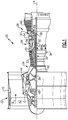
Figure 1 schematically shows a gas turbine engine. -
Figure 2 shows a second embodiment gas turbine engine. -
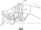
Figure 3 shows a detail of theFigure 2 embodiment. -
Figure 1 schematically illustrates agas turbine engine 20. Thegas turbine engine 20 is disclosed herein as a two-spool turbofan that generally incorporates afan section 22, acompressor section 24, a combustor section 26 and aturbine section 28. - Alternative engines might include an augmentor section (not shown) among other systems or features. The
fan section 22 drives air along a bypass flow path B in a bypass duct defined within anacelle 15, and also drives air along a core flow path C for compression and communication into the combustor section 26 then expansion through theturbine section 28. Although depicted as a two-spool turbofan gas turbine engine in the disclosed non-limiting embodiment, it should be understood that the concepts described herein are not limited to use with two-spool turbofans as the teachings may be applied to other types of turbine engines including three-spool architectures. - The
exemplary engine 20 generally includes alow speed spool 30 and ahigh speed spool 32 mounted for rotation about an engine central longitudinal axis A relative to an enginestatic structure 36 viaseveral bearing systems 38. It should be understood thatvarious bearing systems 38 at various locations may alternatively or additionally be provided, and the location ofbearing systems 38 may be varied as appropriate to the application. - The
low speed spool 30 generally includes aninner shaft 40 that interconnects afan 42, a first (or low) pressure compressor 44 and a first (or low)pressure turbine 46. Theinner shaft 40 is connected to thefan 42 through a speed change mechanism, which in exemplarygas turbine engine 20 is illustrated as a gearedarchitecture 48 to drive thefan 42 at a lower speed than thelow speed spool 30. Thehigh speed spool 32 includes anouter shaft 50 that interconnects a second (or high)pressure compressor 52 and a second (or high)pressure turbine 54. Acombustor 56 is arranged inexemplary gas turbine 20 between thehigh pressure compressor 52 and thehigh pressure turbine 54. Amid-turbine frame 57 of the enginestatic structure 36 is arranged generally between thehigh pressure turbine 54 and thelow pressure turbine 46. Themid-turbine frame 57 further supports bearingsystems 38 in theturbine section 28. Theinner shaft 40 and theouter shaft 50 are concentric and rotate viabearing systems 38 about the engine central longitudinal axis A which is collinear with their longitudinal axes. - The core airflow is compressed by the low pressure compressor 44 then the
high pressure compressor 52, mixed and burned with fuel in thecombustor 56, then expanded over thehigh pressure turbine 54 andlow pressure turbine 46. Themid-turbine frame 57 includesairfoils 59 which are in the core airflow path C. Theturbines low speed spool 30 andhigh speed spool 32 in response to the expansion. It will be appreciated that each of the positions of thefan section 22,compressor section 24, combustor section 26,turbine section 28, and fandrive gear system 48 may be varied. For example,gear system 48 may be located aft of combustor section 26 or even aft ofturbine section 28, andfan section 22 may be positioned forward or aft of the location ofgear system 48. - The
engine 20 in one example is a high-bypass geared aircraft engine. In a further example, theengine 20 bypass ratio is greater than about six, and less than thirty, with an example embodiment being greater than about ten, the gearedarchitecture 48 is an epicyclic gear train, such as a planetary gear system or other gear system, with a gear reduction ratio of greater than about 2.3 and thelow pressure turbine 46 has a pressure ratio that is greater than about five. In one disclosed embodiment, theengine 20 bypass ratio is greater than about ten, the fan diameter is significantly larger than that of the low pressure compressor 44, and thelow pressure turbine 46 has a pressure ratio that is greater than about five and less than 15:1.Low pressure turbine 46 pressure ratio is pressure measured prior to inlet oflow pressure turbine 46 as related to the pressure at the outlet of thelow pressure turbine 46 prior to an exhaust nozzle. The gearedarchitecture 48 may be an epicycle gear train, such as a planetary gear system or other gear system, with a gear reduction ratio of greater than about 2.3:1 and less than 6.0. It should be understood, however, that the above parameters are only exemplary of one embodiment of a geared architecture engine and that the present invention is applicable to other gas turbine engines including direct drive turbofans. - A significant amount of thrust is provided by the bypass flow B due to the high bypass ratio. The
fan section 22 of theengine 20 is designed for a particular flight condition -- typically cruise at about 0.8 Mach and about 35,000 feet (10,668 meters). The flight condition of 0.8 Mach and 35,000 ft (10,668 meters), with the engine at its best fuel consumption - also known as "bucket cruise Thrust Specific Fuel Consumption ('TSFC')" - is the industry standard parameter of lbm of fuel being burned divided by lbf of thrust the engine produces at that minimum point. "Low fan pressure ratio" is the pressure ratio across the fan blade alone, without a Fan Exit Guide Vane ("FEGV") system. The low fan pressure ratio as disclosed herein according to one non-limiting embodiment is less than about 1.45. "Low corrected fan tip speed" is the actual fan tip speed in ft/sec divided by an industry standard temperature correction of [(Tram °R) / (518.7 °R)]0.5(where °R = K x 9/5). The "Low corrected fan tip speed" as disclosed herein according to one non-limiting embodiment is less than about 1150 ft / second (350.5 meters/second). - While the quantities discussed above relate to a compressor in which the gear reduction is intermediate to the low pressure turbine and the fan rotor, many of these quantities might apply to an engine, such as
engine 100 illustrated inFigure 2 , wherein thegear reduction 106 is intermediate to thefan drive turbine 108 and a lowpressure compressor rotor 104, which is driven to rotate at the same speed and in the same direction as afan rotor 102. The speed of thecompressor rotor 104 andfan rotor 102 will be slower than the speed ofturbine 108. - As known, the
low pressure compressor 104 includesblades 105. Thegear reduction 106 is illustrated somewhat schematically, but may be an epicyclic gear reduction. The gear reduction is so-called "straddle mounted" meaning there is abearing 110 supporting it at a forward location and asecond bearing 112 aft of the gear reduction. Alow turbine shaft 115 connectslow turbine 108 withgear reduction system 106. The low turbine shaft could be of any type of geometric shape such as solid, hollow, flexible or non-flexible, providing it transmits torque fromlow turbine 108 to thegear reduction 106. - The
fan drive turbine 108 is provided with athrust bearing 114. This thrust bearing is illustrated aft of acombustor 120. In addition, it is aft of the blades on ahigh pressure turbine 118, which drives thehigh pressure compressor 116. - As mentioned above, there are challenges with such compressors should the
low turbine shaft 115 driving thegear reduction 106 from thefan drive turbine 108 fracture, namely overspeed of the fan drive turbine. Thus,Figure 3 shows features which address this concern. - As shown, the
fan drive turbine 108 includesblades 122 and intermediatestatic vanes 124. Ahub 126 is supported onbearings shaft portion 102 extends forward of thehub 126. The hub is shown pinned at 130 to theshaft portion 102. - In addition, a weakened
portion 134 may be provided aft of thethrust bearing 114. - It should be understood that the shaft will tend to fail at either the
pins 130 or the weakenedportion 134 and aft of thethrust bearing 114. Thepins 130 or weakenedsection 134 will always be the weakest section oflow turbine shaft 115. In the event of excessive torsional overload or other emergency high load condition, pins 130 or weakenedsection 134 will easily fracture before any other portion oflow turbine shaft 115 fails. Since the fracture will occur aft of thethrust bearing 114, the turbine rotor will move rearward andblades 122 will contact thevanes 124 and rotation will be resisted, if not prevented. Thus, the overspeed concern mentioned above will be addressed. - In embodiments, the shear section, be it the weakened
portion 134 or thepin connections 130, are between 1.5 and 2.0 times weaker than any other shaft section between thefan drive turbine 108 and thegear reduction 106. - In an alternative embodiment, the shear section is between 1.15 and 1.5 times weaker than any shaft section between the
fan drive turbine 108 and thegear reduction 106. - As shown, the shear section can be an array of bolts or pins 130, or alternatively is the
thin portion 134. - While the drive input for the
gear reduction 106 is not specifically illustrated, it may be a flexible connection or it may be a more rigid connection. In addition, while thegear reduction 106 is disclosed as being epicyclic, this disclosure may extend to non-epicyclic gear reductions. - The thrust bearings as disclosed and claimed may be any type thrust bearing, including ball bearings, tapered roller bearings and spherical roller bearings, among others.
- Although an embodiment of this invention has been disclosed, a worker of ordinary skill in this art would recognize that certain modifications would come within the scope of this invention. For that reason, the following claims should be studied to determine the true scope and content of this invention.
Claims (11)
- A gas turbine engine (100) comprising:a fan (42) and a low pressure compressor (104), said fan (42) and said low pressure compressor (104) configured for rotating at a common speed and in a common direction;a fan drive turbine (108) configured for driving a gear reduction (106), in turn configured for driving said low pressure compressor (104) and said fan (42) at a speed which is slower than a speed of said fan drive turbine (108);a combustor (120) intermediate said low pressure compressor (104) and said fan drive turbine (108);a thrust bearing (114) mounting said fan drive turbine (108), said thrust bearing (114) being aft of a location of said combustor (120); anda shear section (130, 134) in a drive connection connecting said fan drive turbine (108) to said gear reduction (106) that is weaker than other portions of said drive connection, said shear section (130, 134) being aft of said thrust bearing (114).
- The gas turbine engine as set forth in claim 1, comprising a high pressure turbine (118) and a high pressure compressor (116), wherein said shear section is aft of said blades on high pressure turbine (118).
- The gas turbine engine as set forth in claim 1 or 2, wherein said gear reduction (106) is supported on a bearing (110) forward of said gear reduction (106) and on a second bearing (112) which is aft of said gear reduction (106).
- The gas turbine engine as set forth in claim 1, 2 or 3, wherein said shear section (130, 134) is between 1.5 and 2.0 times weaker than any other shaft section between said fan drive turbine (108) and said gear reduction (106).
- The gas turbine engine as set forth in claim 1, 2 or 3, wherein said shear section (130, 134) is between 1.15 and 1.5 times weaker than any other shaft section between said fan drive turbine (108) and said gear reduction (106).
- The gas turbine engine as set forth in any preceding claim, wherein said shear section (130, 134) is provided by connections (130) connecting a shaft section (102) extending toward said gear reduction (106) to a hub (126) of said fan drive turbine (108).
- The gas turbine engine as set forth in claim 6, wherein said connections (130) are bolts or pins (130).
- The gas turbine engine as set forth in any of claims 1 to 5, wherein said shear section is provided by a thin portion (134).
- The gas turbine engine as set forth in claim 8, wherein said thin portion (134) is in a hub (126) connecting said fan drive turbine (108) to a shaft (102).
- The gas turbine engine as set forth in any preceding claim, wherein said fan drive turbine (108) is supported on said thrust bearing (114) and on a second bearing (128) which is aft of said thrust bearing (114).
- The gas turbine engine as set forth in any preceding claim, wherein said gear reduction (106) is an epicyclic gear reduction (106).
Applications Claiming Priority (2)
| Application Number | Priority Date | Filing Date | Title |
|---|---|---|---|
| US15/619,799 US10738646B2 (en) | 2017-06-12 | 2017-06-12 | Geared turbine engine with gear driving low pressure compressor and fan at common speed, and failsafe overspeed protection and shear section |
| EP18176983.7A EP3415727B1 (en) | 2017-06-12 | 2018-06-11 | Gas turbine engine |
Related Parent Applications (1)
| Application Number | Title | Priority Date | Filing Date |
|---|---|---|---|
| EP18176983.7A Division EP3415727B1 (en) | 2017-06-12 | 2018-06-11 | Gas turbine engine |
Publications (1)
| Publication Number | Publication Date |
|---|---|
| EP3722567A1 true EP3722567A1 (en) | 2020-10-14 |
Family
ID=62599478
Family Applications (2)
| Application Number | Title | Priority Date | Filing Date |
|---|---|---|---|
| EP20174064.4A Withdrawn EP3722567A1 (en) | 2017-06-12 | 2018-06-11 | Gas turbine engine |
| EP18176983.7A Active EP3415727B1 (en) | 2017-06-12 | 2018-06-11 | Gas turbine engine |
Family Applications After (1)
| Application Number | Title | Priority Date | Filing Date |
|---|---|---|---|
| EP18176983.7A Active EP3415727B1 (en) | 2017-06-12 | 2018-06-11 | Gas turbine engine |
Country Status (2)
| Country | Link |
|---|---|
| US (2) | US10738646B2 (en) |
| EP (2) | EP3722567A1 (en) |
Families Citing this family (15)
| Publication number | Priority date | Publication date | Assignee | Title |
|---|---|---|---|---|
| US10738646B2 (en) * | 2017-06-12 | 2020-08-11 | Raytheon Technologies Corporation | Geared turbine engine with gear driving low pressure compressor and fan at common speed, and failsafe overspeed protection and shear section |
| US10711797B2 (en) | 2017-06-16 | 2020-07-14 | General Electric Company | Inlet pre-swirl gas turbine engine |
| US10724435B2 (en) | 2017-06-16 | 2020-07-28 | General Electric Co. | Inlet pre-swirl gas turbine engine |
| US10794396B2 (en) | 2017-06-16 | 2020-10-06 | General Electric Company | Inlet pre-swirl gas turbine engine |
| US10815886B2 (en) * | 2017-06-16 | 2020-10-27 | General Electric Company | High tip speed gas turbine engine |
| GB201918779D0 (en) | 2019-12-19 | 2020-02-05 | Rolls Royce Plc | Shaft bearings |
| GB201918783D0 (en) | 2019-12-19 | 2020-02-05 | Rolls Royce Plc | Shaft with three bearings |
| GB201918780D0 (en) | 2019-12-19 | 2020-02-05 | Rolls Royce Plc | Shaft bearings for gas turbine engine |
| GB201918782D0 (en) | 2019-12-19 | 2020-02-05 | Rolls Royce Plc | Shaft bearing arrangement |
| GB201918777D0 (en) | 2019-12-19 | 2020-02-05 | Rolls Royce Plc | Shaft bearing arrangement |
| GB201918781D0 (en) * | 2019-12-19 | 2020-02-05 | Rolls Royce Plc | Improved shaft bearing positioning in a gas turbine engine |
| US11499447B2 (en) * | 2020-01-15 | 2022-11-15 | Pratt & Whitney Canada Corp. | Bearing support with frangible tabs |
| FR3109401B1 (en) * | 2020-04-16 | 2022-03-18 | Safran Aircraft Engines | AIRCRAFT TURBOMACHINE EQUIPPED WITH FUSE SCREWS |
| US11428160B2 (en) | 2020-12-31 | 2022-08-30 | General Electric Company | Gas turbine engine with interdigitated turbine and gear assembly |
| US11965424B2 (en) | 2022-06-21 | 2024-04-23 | General Electric Company | Electronic overspeed protection system and method |
Citations (2)
| Publication number | Priority date | Publication date | Assignee | Title |
|---|---|---|---|---|
| US20030143063A1 (en) * | 2001-12-19 | 2003-07-31 | Coxhead Todd M. | Rotor assemblies for gas turbine engines |
| US20160376984A1 (en) * | 2015-06-23 | 2016-12-29 | United Technologies Corporation | Geared turbofan with independent flexible ring gears and oil collectors |
Family Cites Families (120)
| Publication number | Priority date | Publication date | Assignee | Title |
|---|---|---|---|---|
| US2258792A (en) | 1941-04-12 | 1941-10-14 | Westinghouse Electric & Mfg Co | Turbine blading |
| US3021731A (en) | 1951-11-10 | 1962-02-20 | Wilhelm G Stoeckicht | Planetary gear transmission |
| US2936655A (en) | 1955-11-04 | 1960-05-17 | Gen Motors Corp | Self-aligning planetary gearing |
| US3194487A (en) | 1963-06-04 | 1965-07-13 | United Aircraft Corp | Noise abatement method and apparatus |
| US3287906A (en) | 1965-07-20 | 1966-11-29 | Gen Motors Corp | Cooled gas turbine vanes |
| US3352178A (en) | 1965-11-15 | 1967-11-14 | Gen Motors Corp | Planetary gearing |
| US3412560A (en) | 1966-08-03 | 1968-11-26 | Gen Motors Corp | Jet propulsion engine with cooled combustion chamber, fuel heater, and induced air-flow |
| US3664612A (en) | 1969-12-22 | 1972-05-23 | Boeing Co | Aircraft engine variable highlight inlet |
| GB1350431A (en) | 1971-01-08 | 1974-04-18 | Secr Defence | Gearing |
| US3892358A (en) | 1971-03-17 | 1975-07-01 | Gen Electric | Nozzle seal |
| US3765623A (en) | 1971-10-04 | 1973-10-16 | Mc Donnell Douglas Corp | Air inlet |
| US3747343A (en) | 1972-02-10 | 1973-07-24 | United Aircraft Corp | Low noise prop-fan |
| GB1418905A (en) | 1972-05-09 | 1975-12-24 | Rolls Royce | Gas turbine engines |
| US3843277A (en) | 1973-02-14 | 1974-10-22 | Gen Electric | Sound attenuating inlet duct |
| US3988889A (en) | 1974-02-25 | 1976-11-02 | General Electric Company | Cowling arrangement for a turbofan engine |
| US3932058A (en) | 1974-06-07 | 1976-01-13 | United Technologies Corporation | Control system for variable pitch fan propulsor |
| US3935558A (en) | 1974-12-11 | 1976-01-27 | United Technologies Corporation | Surge detector for turbine engines |
| US4130872A (en) | 1975-10-10 | 1978-12-19 | The United States Of America As Represented By The Secretary Of The Air Force | Method and system of controlling a jet engine for avoiding engine surge |
| GB1516041A (en) | 1977-02-14 | 1978-06-28 | Secr Defence | Multistage axial flow compressor stators |
| US4240250A (en) | 1977-12-27 | 1980-12-23 | The Boeing Company | Noise reducing air inlet for gas turbine engines |
| GB2041090A (en) | 1979-01-31 | 1980-09-03 | Rolls Royce | By-pass gas turbine engines |
| US4284174A (en) | 1979-04-18 | 1981-08-18 | Avco Corporation | Emergency oil/mist system |
| US4220171A (en) | 1979-05-14 | 1980-09-02 | The United States Of America As Represented By The Administrator Of The National Aeronautics And Space Administration | Curved centerline air intake for a gas turbine engine |
| US4289360A (en) | 1979-08-23 | 1981-09-15 | General Electric Company | Bearing damper system |
| DE2940446C2 (en) | 1979-10-05 | 1982-07-08 | B. Braun Melsungen Ag, 3508 Melsungen | Cultivation of animal cells in suspension and monolayer cultures in fermentation vessels |
| US4380896A (en) | 1980-09-22 | 1983-04-26 | The United States Of America As Represented By The Secretary Of The Army | Annular combustor having ceramic liner |
| US4478551A (en) | 1981-12-08 | 1984-10-23 | United Technologies Corporation | Turbine exhaust case design |
| US4512159A (en) | 1984-04-02 | 1985-04-23 | United Technologies Corporation | Clip attachment |
| US4722357A (en) | 1986-04-11 | 1988-02-02 | United Technologies Corporation | Gas turbine engine nacelle |
| US4696156A (en) | 1986-06-03 | 1987-09-29 | United Technologies Corporation | Fuel and oil heat management system for a gas turbine engine |
| US4979362A (en) | 1989-05-17 | 1990-12-25 | Sundstrand Corporation | Aircraft engine starting and emergency power generating system |
| US5058617A (en) | 1990-07-23 | 1991-10-22 | General Electric Company | Nacelle inlet for an aircraft gas turbine engine |
| US5141400A (en) | 1991-01-25 | 1992-08-25 | General Electric Company | Wide chord fan blade |
| US5102379A (en) | 1991-03-25 | 1992-04-07 | United Technologies Corporation | Journal bearing arrangement |
| US5317877A (en) | 1992-08-03 | 1994-06-07 | General Electric Company | Intercooled turbine blade cooling air feed system |
| US5291732A (en) | 1993-02-08 | 1994-03-08 | General Electric Company | Combustor liner support assembly |
| US5447411A (en) | 1993-06-10 | 1995-09-05 | Martin Marietta Corporation | Light weight fan blade containment system |
| US5466198A (en) | 1993-06-11 | 1995-11-14 | United Technologies Corporation | Geared drive system for a bladed propulsor |
| US5361580A (en) | 1993-06-18 | 1994-11-08 | General Electric Company | Gas turbine engine rotor support system |
| US5524847A (en) | 1993-09-07 | 1996-06-11 | United Technologies Corporation | Nacelle and mounting arrangement for an aircraft engine |
| RU2082824C1 (en) | 1994-03-10 | 1997-06-27 | Московский государственный авиационный институт (технический университет) | Method of protection of heat-resistant material from effect of high-rapid gaseous flow of corrosive media (variants) |
| US5433674A (en) | 1994-04-12 | 1995-07-18 | United Technologies Corporation | Coupling system for a planetary gear train |
| US5778659A (en) | 1994-10-20 | 1998-07-14 | United Technologies Corporation | Variable area fan exhaust nozzle having mechanically separate sleeve and thrust reverser actuation systems |
| WO1997000381A1 (en) | 1994-12-14 | 1997-01-03 | United Technologies Corporation | Compressor stall and surge control using airflow asymmetry measurement |
| JP2969075B2 (en) | 1996-02-26 | 1999-11-02 | ジャパンゴアテックス株式会社 | Degassing device |
| US5634767A (en) | 1996-03-29 | 1997-06-03 | General Electric Company | Turbine frame having spindle mounted liner |
| US5857836A (en) | 1996-09-10 | 1999-01-12 | Aerodyne Research, Inc. | Evaporatively cooled rotor for a gas turbine engine |
| US5975841A (en) | 1997-10-03 | 1999-11-02 | Thermal Corp. | Heat pipe cooling for turbine stators |
| US5985470A (en) | 1998-03-16 | 1999-11-16 | General Electric Company | Thermal/environmental barrier coating system for silicon-based materials |
| US6240719B1 (en) | 1998-12-09 | 2001-06-05 | General Electric Company | Fan decoupler system for a gas turbine engine |
| US6517341B1 (en) | 1999-02-26 | 2003-02-11 | General Electric Company | Method to prevent recession loss of silica and silicon-containing materials in combustion gas environments |
| US6410148B1 (en) | 1999-04-15 | 2002-06-25 | General Electric Co. | Silicon based substrate with environmental/ thermal barrier layer |
| US6315815B1 (en) | 1999-12-16 | 2001-11-13 | United Technologies Corporation | Membrane based fuel deoxygenator |
| US6223616B1 (en) | 1999-12-22 | 2001-05-01 | United Technologies Corporation | Star gear system with lubrication circuit and lubrication method therefor |
| US6318070B1 (en) | 2000-03-03 | 2001-11-20 | United Technologies Corporation | Variable area nozzle for gas turbine engines driven by shape memory alloy actuators |
| US6444335B1 (en) | 2000-04-06 | 2002-09-03 | General Electric Company | Thermal/environmental barrier coating for silicon-containing materials |
| JP3478531B2 (en) | 2000-04-21 | 2003-12-15 | 川崎重工業株式会社 | Gas turbine ceramic component support structure |
| US6397603B1 (en) | 2000-05-05 | 2002-06-04 | The United States Of America As Represented By The Secretary Of The Air Force | Conbustor having a ceramic matrix composite liner |
| EP1780387A3 (en) | 2000-09-05 | 2007-07-18 | Sudarshan Paul Dev | Nested core gas turbine engine |
| US6447248B1 (en) | 2000-10-20 | 2002-09-10 | General Electric Company | Bearing support fuse |
| JP3600911B2 (en) | 2001-01-25 | 2004-12-15 | 川崎重工業株式会社 | Liner support structure for annular combustor |
| US6428269B1 (en) | 2001-04-18 | 2002-08-06 | United Technologies Corporation | Turbine engine bearing support |
| EP1381811A1 (en) | 2001-04-27 | 2004-01-21 | Siemens Aktiengesellschaft | Combustion chamber, in particular of a gas turbine |
| US6708482B2 (en) | 2001-11-29 | 2004-03-23 | General Electric Company | Aircraft engine with inter-turbine engine frame |
| US6655147B2 (en) | 2002-04-10 | 2003-12-02 | General Electric Company | Annular one-piece corrugated liner for combustor of a gas turbine engine |
| US6607165B1 (en) | 2002-06-28 | 2003-08-19 | General Electric Company | Aircraft engine mount with single thrust link |
| FR2845126B1 (en) | 2002-09-26 | 2004-12-03 | Snecma Moteurs | TRACTION COUPLER DEVICE |
| US6814541B2 (en) | 2002-10-07 | 2004-11-09 | General Electric Company | Jet aircraft fan case containment design |
| US7021042B2 (en) | 2002-12-13 | 2006-04-04 | United Technologies Corporation | Geartrain coupling for a turbofan engine |
| US6904757B2 (en) | 2002-12-20 | 2005-06-14 | General Electric Company | Mounting assembly for the forward end of a ceramic matrix composite liner in a gas turbine engine combustor |
| US6895761B2 (en) | 2002-12-20 | 2005-05-24 | General Electric Company | Mounting assembly for the aft end of a ceramic matrix composite liner in a gas turbine engine combustor |
| US6895757B2 (en) | 2003-02-10 | 2005-05-24 | General Electric Company | Sealing assembly for the aft end of a ceramic matrix composite liner in a gas turbine engine combustor |
| US6709492B1 (en) | 2003-04-04 | 2004-03-23 | United Technologies Corporation | Planar membrane deoxygenator |
| US6931855B2 (en) | 2003-05-12 | 2005-08-23 | Siemens Westinghouse Power Corporation | Attachment system for coupling combustor liners to a carrier of a turbine combustor |
| US7152411B2 (en) | 2003-06-27 | 2006-12-26 | General Electric Company | Rabbet mounted combuster |
| DE102004016246A1 (en) | 2004-04-02 | 2005-10-20 | Mtu Aero Engines Gmbh | Turbine, in particular low-pressure turbine, a gas turbine, in particular an aircraft engine |
| US7328580B2 (en) | 2004-06-23 | 2008-02-12 | General Electric Company | Chevron film cooled wall |
| US7237389B2 (en) | 2004-11-18 | 2007-07-03 | Siemens Power Generation, Inc. | Attachment system for ceramic combustor liner |
| GB0506685D0 (en) | 2005-04-01 | 2005-05-11 | Hopkins David R | A design to increase and smoothly improve the throughput of fluid (air or gas) through the inlet fan (or fans) of an aero-engine system |
| US7374403B2 (en) | 2005-04-07 | 2008-05-20 | General Electric Company | Low solidity turbofan |
| EP1928952B1 (en) | 2005-09-28 | 2014-07-09 | Entrotech Composites, LLC. | Braid-reinforced composites and processes for their preparation |
| US7546743B2 (en) | 2005-10-12 | 2009-06-16 | General Electric Company | Bolting configuration for joining ceramic combustor liner to metal mounting attachments |
| US7603844B2 (en) | 2005-10-19 | 2009-10-20 | General Electric Company | Gas turbine engine assembly and methods of assembling same |
| US7591754B2 (en) | 2006-03-22 | 2009-09-22 | United Technologies Corporation | Epicyclic gear train integral sun gear coupling design |
| BE1017135A3 (en) | 2006-05-11 | 2008-03-04 | Hansen Transmissions Int | A GEARBOX FOR A WIND TURBINE. |
| US20080003096A1 (en) | 2006-06-29 | 2008-01-03 | United Technologies Corporation | High coverage cooling hole shape |
| JP4911344B2 (en) | 2006-07-04 | 2012-04-04 | 株式会社Ihi | Turbofan engine |
| US7926260B2 (en) | 2006-07-05 | 2011-04-19 | United Technologies Corporation | Flexible shaft for gas turbine engine |
| US8585538B2 (en) | 2006-07-05 | 2013-11-19 | United Technologies Corporation | Coupling system for a star gear train in a gas turbine engine |
| US8141370B2 (en) | 2006-08-08 | 2012-03-27 | General Electric Company | Methods and apparatus for radially compliant component mounting |
| US7632064B2 (en) | 2006-09-01 | 2009-12-15 | United Technologies Corporation | Variable geometry guide vane for a gas turbine engine |
| US7662059B2 (en) | 2006-10-18 | 2010-02-16 | United Technologies Corporation | Lubrication of windmilling journal bearings |
| FR2907839B1 (en) * | 2006-10-25 | 2011-06-17 | Snecma | METHOD FOR REDUCING SPEED IN CASE OF TURBINE SHAFT BREAKAGE OF GAS TURBINE ENGINE |
| US7841165B2 (en) | 2006-10-31 | 2010-11-30 | General Electric Company | Gas turbine engine assembly and methods of assembling same |
| US8020665B2 (en) | 2006-11-22 | 2011-09-20 | United Technologies Corporation | Lubrication system with extended emergency operability |
| US8017188B2 (en) | 2007-04-17 | 2011-09-13 | General Electric Company | Methods of making articles having toughened and untoughened regions |
| US7950237B2 (en) | 2007-06-25 | 2011-05-31 | United Technologies Corporation | Managing spool bearing load using variable area flow nozzle |
| US20120124964A1 (en) | 2007-07-27 | 2012-05-24 | Hasel Karl L | Gas turbine engine with improved fuel efficiency |
| US8256707B2 (en) | 2007-08-01 | 2012-09-04 | United Technologies Corporation | Engine mounting configuration for a turbofan gas turbine engine |
| US8205432B2 (en) | 2007-10-03 | 2012-06-26 | United Technologies Corporation | Epicyclic gear train for turbo fan engine |
| US8104289B2 (en) | 2007-10-09 | 2012-01-31 | United Technologies Corp. | Systems and methods involving multiple torque paths for gas turbine engines |
| US8128021B2 (en) | 2008-06-02 | 2012-03-06 | United Technologies Corporation | Engine mount system for a turbofan gas turbine engine |
| US7997868B1 (en) | 2008-11-18 | 2011-08-16 | Florida Turbine Technologies, Inc. | Film cooling hole for turbine airfoil |
| US8307626B2 (en) | 2009-02-26 | 2012-11-13 | United Technologies Corporation | Auxiliary pump system for fan drive gear system |
| US8181441B2 (en) | 2009-02-27 | 2012-05-22 | United Technologies Corporation | Controlled fan stream flow bypass |
| US8745989B2 (en) | 2009-04-09 | 2014-06-10 | Pratt & Whitney Canada Corp. | Reverse flow ceramic matrix composite combustor |
| US8172716B2 (en) | 2009-06-25 | 2012-05-08 | United Technologies Corporation | Epicyclic gear system with superfinished journal bearing |
| US8215115B2 (en) | 2009-09-28 | 2012-07-10 | Hamilton Sundstrand Corporation | Combustor interface sealing arrangement |
| US9170616B2 (en) | 2009-12-31 | 2015-10-27 | Intel Corporation | Quiet system cooling using coupled optimization between integrated micro porous absorbers and rotors |
| US8905713B2 (en) | 2010-05-28 | 2014-12-09 | General Electric Company | Articles which include chevron film cooling holes, and related processes |
| US8739547B2 (en) | 2011-06-23 | 2014-06-03 | United Technologies Corporation | Gas turbine engine joint having a metallic member, a CMC member, and a ceramic key |
| US20130152591A1 (en) | 2011-12-16 | 2013-06-20 | General Electric Company | System of integrating baffles for enhanced cooling of cmc liners |
| US20130186058A1 (en) | 2012-01-24 | 2013-07-25 | William G. Sheridan | Geared turbomachine fan and compressor rotation |
| US9017010B2 (en) | 2012-01-31 | 2015-04-28 | United Technologies Corporation | Turbomachine geared architecture support assembly |
| US9926850B2 (en) * | 2013-02-11 | 2018-03-27 | United Technologies Corporation | Compound star gear system with rolling element bearings |
| US10190496B2 (en) * | 2013-03-15 | 2019-01-29 | United Technologies Corporation | Turbofan engine bearing and gearbox arrangement |
| JP2016519242A (en) | 2013-04-14 | 2016-06-30 | ゼネラル・エレクトリック・カンパニイ | Engine overspeed protection system with thrust control |
| FR3022890B1 (en) * | 2014-06-25 | 2018-01-05 | Snecma | TURBOMACHINE COMPRISING A MEANS FOR DECOUPLING A BLOWER |
| US20170096941A1 (en) | 2015-10-06 | 2017-04-06 | General Electric Company | Gas turbine gearbox input shaft |
| US10738646B2 (en) * | 2017-06-12 | 2020-08-11 | Raytheon Technologies Corporation | Geared turbine engine with gear driving low pressure compressor and fan at common speed, and failsafe overspeed protection and shear section |
-
2017
- 2017-06-12 US US15/619,799 patent/US10738646B2/en active Active
-
2018
- 2018-06-11 EP EP20174064.4A patent/EP3722567A1/en not_active Withdrawn
- 2018-06-11 EP EP18176983.7A patent/EP3415727B1/en active Active
-
2020
- 2020-07-28 US US16/940,538 patent/US11384657B2/en active Active
Patent Citations (2)
| Publication number | Priority date | Publication date | Assignee | Title |
|---|---|---|---|---|
| US20030143063A1 (en) * | 2001-12-19 | 2003-07-31 | Coxhead Todd M. | Rotor assemblies for gas turbine engines |
| US20160376984A1 (en) * | 2015-06-23 | 2016-12-29 | United Technologies Corporation | Geared turbofan with independent flexible ring gears and oil collectors |
Also Published As
| Publication number | Publication date |
|---|---|
| US20180355802A1 (en) | 2018-12-13 |
| US20210087944A1 (en) | 2021-03-25 |
| EP3415727B1 (en) | 2020-05-13 |
| US10738646B2 (en) | 2020-08-11 |
| US11384657B2 (en) | 2022-07-12 |
| EP3415727A1 (en) | 2018-12-19 |
Similar Documents
| Publication | Publication Date | Title |
|---|---|---|
| US11384657B2 (en) | Geared gas turbine engine with gear driving low pressure compressor and fan at a common speed and a shear section to provide overspeed protection | |
| US12385413B2 (en) | Geared turbofan with overspeed protection | |
| EP2807358B1 (en) | Geared turbomachine fan and compressor rotation | |
| EP3584427B1 (en) | Intercooled cooling air with low temperature bearing compartment air | |
| EP4098861B1 (en) | Geared turbofan | |
| EP3111057B1 (en) | Tie rod connection for mid-turbine frame | |
| EP3052812A1 (en) | Compressor area splits for geared turbofan | |
| EP4375494B1 (en) | Geared turbofan with over-speed protection | |
| US10227884B2 (en) | Fan platform with leading edge tab | |
| US10302014B2 (en) | Modifying a gas turbine engine to use a high pressure compressor as a low pressure compressor | |
| EP3176410B1 (en) | Geared turbofan with four star/planetary gear reduction | |
| EP2955325B1 (en) | Geared turbofan with integrally bladed rotor |
Legal Events
| Date | Code | Title | Description |
|---|---|---|---|
| PUAI | Public reference made under article 153(3) epc to a published international application that has entered the european phase |
Free format text: ORIGINAL CODE: 0009012 |
|
| STAA | Information on the status of an ep patent application or granted ep patent |
Free format text: STATUS: THE APPLICATION HAS BEEN PUBLISHED |
|
| AC | Divisional application: reference to earlier application |
Ref document number: 3415727 Country of ref document: EP Kind code of ref document: P |
|
| AK | Designated contracting states |
Kind code of ref document: A1 Designated state(s): AL AT BE BG CH CY CZ DE DK EE ES FI FR GB GR HR HU IE IS IT LI LT LU LV MC MK MT NL NO PL PT RO RS SE SI SK SM TR |
|
| STAA | Information on the status of an ep patent application or granted ep patent |
Free format text: STATUS: THE APPLICATION IS DEEMED TO BE WITHDRAWN |
|
| 18D | Application deemed to be withdrawn |
Effective date: 20210415 |