EP3722496A1 - Clothes iron base and clothes iron device - Google Patents
Clothes iron base and clothes iron device Download PDFInfo
- Publication number
- EP3722496A1 EP3722496A1 EP17934209.2A EP17934209A EP3722496A1 EP 3722496 A1 EP3722496 A1 EP 3722496A1 EP 17934209 A EP17934209 A EP 17934209A EP 3722496 A1 EP3722496 A1 EP 3722496A1
- Authority
- EP
- European Patent Office
- Prior art keywords
- iron
- limiting
- placing surface
- boss
- clamping mechanism
- Prior art date
- Legal status (The legal status is an assumption and is not a legal conclusion. Google has not performed a legal analysis and makes no representation as to the accuracy of the status listed.)
- Granted
Links
Images



Classifications
-
- D—TEXTILES; PAPER
- D06—TREATMENT OF TEXTILES OR THE LIKE; LAUNDERING; FLEXIBLE MATERIALS NOT OTHERWISE PROVIDED FOR
- D06F—LAUNDERING, DRYING, IRONING, PRESSING OR FOLDING TEXTILE ARTICLES
- D06F75/00—Hand irons
- D06F75/08—Hand irons internally heated by electricity
- D06F75/10—Hand irons internally heated by electricity with means for supplying steam to the article being ironed
- D06F75/12—Hand irons internally heated by electricity with means for supplying steam to the article being ironed the steam being produced from water supplied to the iron from an external source
-
- D—TEXTILES; PAPER
- D06—TREATMENT OF TEXTILES OR THE LIKE; LAUNDERING; FLEXIBLE MATERIALS NOT OTHERWISE PROVIDED FOR
- D06F—LAUNDERING, DRYING, IRONING, PRESSING OR FOLDING TEXTILE ARTICLES
- D06F75/00—Hand irons
- D06F75/40—Stands or supports attached to the iron
Definitions
- This application relates to the technical field of household electrical appliances, in particular to an iron base and an iron device using the iron base.
- Existing iron device generally includes a connected iron and an iron base.
- the iron can be placed on the iron base to avoid exposing the high-temperature ironing surface of the iron.
- most of the iron device currently on the market has no effective fixing structure on the iron base, so there is a risk that the iron device may fall easily during use or movement, thereby causing a safety accident.
- the main object of this application is to provide an iron base, which aims to effectively prevent the iron from falling off the iron base and improve the safety of the iron device.
- this application provides an iron base.
- An iron placing surface is provided on an upper end of the iron base, a fixing portion configured for clamping a rear end of an iron is provided at a rear portion of the iron placing surface, a clamping mechanism is configured to be rotatably connected with a front portion of the iron placing surface, the clamping mechanism is configured to rotate relative to the iron placing surface and has an open position and a clamping position, and the clamping mechanism is configured to clamp a front end of the iron when the clamping mechanism is at the clamping position.
- the clamping mechanism includes a positioning boss and a positioning baffle
- the positioning boss is configured to be rotatably connected to the front portion of the iron placing surface
- the positioning baffle is provided at an end portion of the positioning boss away from the iron placing surface
- the positioning boss is configured to be opposite to the fixing portion when the positioning boss is at the clamping position
- the positioning baffle is configured to extend toward the fixing portion when the positioning baffle is at the clamping position, wherein the positioning baffle, the positioning boss and the iron placing surface enclose a positioning space for receiving the front end of the iron.
- the positioning boss includes two ends extending along a profile extension direction of the front portion of the iron placing surface when the positioning boss is at the clamping position, one end is rotatably connected with the front portion of the iron placing surface, the other end defines a limiting groove on a surface facing the iron placing surface, the iron placing surface is further provided with a limiting projection at the front portion, and the limiting projection is clamped in the limiting groove.
- the iron placing surface further defines a first mounting groove at the front portion, a lower end of the limiting projection is received in the first mounting groove, a first elastic member is provided between a bottom wall of the first mounting groove and the limiting projection, one end of the first elastic member abuts against the bottom wall of the first mounting groove, and the other end of the first elastic member abuts against a surface of the limiting projection facing the bottom wall of the first mounting groove.
- an end of the positioning boss not rotatably connected to the front portion of the iron placing surface defines a second mounting groove
- the second mounting groove is arranged on a surface of the positioning boss away from the iron placing surface
- the clamping mechanism further includes a button provided in the second mounting groove
- the second mounting groove defines an avoiding opening in communication with the limiting groove on a bottom wall
- an abutting portion protrudes from a lower end of the button, and the abutting portion passes through the avoiding opening and abuts against an upper end of the limiting projection when the abutting portion is at the clamping position.
- a surface of the positioning boss facing the iron placing surface further defines a receiving cavity
- a stop rib protrudes from the front portion of the iron placing surface and received in the receiving cavity
- the clamping mechanism further includes a second elastic member received in the receiving cavity, one end of the second elastic member abuts against the stop rib, and the other end of the second elastic member abuts against an inner wall of the receiving cavity to drive the clamping mechanism to rotate from the clamping position to the open position.
- the iron placing surface defines a rotating shaft hole at the front portion, a rotating shaft is arranged on an end of the positioning boss not defining the limiting groove toward the rotating shaft hole, and the rotating shaft is inserted into the rotating shaft hole.
- the fixing portion includes a first limiting boss and a limiting baffle
- the first limiting boss is provided at the rear portion of the iron placing surface
- the limiting baffle is provided at an end portion of the first limiting boss away from the iron placing surface
- the limiting baffle is configured to extend toward the front portion of the iron placing surface, wherein the limiting baffle, the first limiting boss and the iron placing surface enclose a limiting space for receiving the rear end of the iron.
- one second limiting boss respectively protrudes from each of two side portions of the iron placing surface, and the second limiting boss is configured to extend along a profile extension direction of the corresponding side portion.
- an end of the second limiting boss facing the first limiting boss is connected to the first limiting boss, an end of the second limiting boss facing the clamping mechanism abuts against the clamping mechanism, wherein the iron placing surface, the first limiting boss, the clamping mechanism, and two second limiting bosses enclose an iron placing groove.
- This application further provides an iron device, including an iron and an iron base, an iron placing surface is provided on an upper end of the iron base, a fixing portion configured for clamping a rear end of the iron is provided at a rear portion of the iron placing surface, a clamping mechanism is configured to be rotatably connected with a front portion of the iron placing surface, the clamping mechanism is configured to rotate relative to the iron placing surface and has an open position and a clamping position, the clamping mechanism is configured to clamp a front end of the iron when the clamping mechanism is at the clamping position, the iron is placed on the iron placing surface of the iron base, the fixing portion of the iron base clamps a rear end of the iron, and the clamping mechanism of the iron base clamps the front end of the iron when the clamping mechanism is at the clamping position.
- the clamping mechanism includes a positioning boss and a positioning baffle
- the positioning boss is configured to be rotatably connected to the front portion of the iron placing surface
- the positioning baffle is provided at an end portion of the positioning boss away from the iron placing surface
- the positioning boss is configured to be opposite to the fixing portion when the positioning boss is at the clamping position
- the positioning baffle is configured to extend toward the fixing portion when the positioning baffle is at the clamping position, wherein the positioning baffle, the positioning boss and the iron placing surface enclose a positioning space for receiving the front end of the iron.
- the positioning boss includes two ends extending along a profile extension direction of the front portion of the iron placing surface when the positioning boss is at the clamping position, one end is rotatably connected with the front portion of the iron placing surface, the other end defines a limiting groove on a surface facing the iron placing surface, the iron placing surface is further provided with a limiting projection at the front portion, and the limiting projection clamped in the limiting groove.
- the iron placing surface further defines a first mounting groove at the front portion, a lower end of the limiting projection is received in the first mounting groove, a first elastic member is provided between a bottom wall of the first mounting groove and the limiting projection, one end of the first elastic member abuts against the bottom wall of the first mounting groove, and the other end of the first elastic member abuts against a surface of the limiting projection facing the bottom wall of the first mounting groove.
- an end of the positioning boss not rotatably connected to the front portion of the iron placing surface defines a second mounting groove
- the second mounting groove is arranged on a surface of the positioning boss away from the iron placing surface
- the clamping mechanism further includes a button provided in the second mounting groove
- a bottom wall of the second mounting groove is proved with an avoiding opening in communication with the limiting groove
- an abutting portion protrudes from a lower end of the button, and the abutting portion passes through the avoiding opening and abuts against an upper end of the limiting projection when the abutting portion is at the clamping position.
- the fixing portion includes a first limiting boss and a limiting baffle
- the first limiting boss is provided at the rear portion of the iron placing surface
- the limiting baffle is provided at an end portion of the first limiting boss away from the iron placing surface
- the limiting baffle is configured to extend toward the front portion of the iron placing surface, wherein the limiting baffle, the first limiting boss and the iron placing surface enclose a limiting space for receiving the rear end of the iron.
- the fixing portion and the clamping mechanism are provided on the iron placing surface of the iron base.
- the fixing portion is disposed at the rear portion of the iron placing surface and configured to clamp the rear end of the iron.
- the clamping mechanism is disposed at the front portion of the iron placing surface and configured to clamp the front end of the iron.
- the fixing portion and the clamping mechanism may respectively clamp and fix the rear end and the front end of the iron, which effectively improves the stability of the iron placed on the iron base, thereby effectively preventing the iron from falling off the iron base and improving the safety of the iron device.
- the clamping mechanism and the iron placing surface are rotatably connected, and the clamping mechanism rotates relative to the iron placing surface to have an open position and a clamping position.
- the clamping mechanism clamps the front end of the iron when the clamping mechanism is at the clamping position. In this way, the clamping and loosening of the front end of the iron may be easily achieved through the rotation of the clamping mechanism, so that the process of placing and fixing the iron and the process of loosening and removing the iron are simple, convenient, and reliable.
- the above structure is not only convenient for manufacturing, but also conducive to mounting and assembly, so that production efficiency and assembly efficiency may be effectively improved.
- first, second, etc. are for descriptive purposes only, and cannot be understood as indicating or implying their relative importance or implicitly indicating the number of technical features indicated.
- the features defined with “first” and “second” may include at least one of the features either explicitly or implicitly.
- the meaning of “plurality” is at least two, such as two, three, etc., unless specifically defined otherwise.
- connection and “fixed” should be understood in a broad sense.
- “fixed” may be a fixed connection, a detachable connection, or integrated; it may be a mechanical connection or an electrical connection; it may be directly connected or indirectly connected through an intermediary; it may be the connection between two elements or the interaction between two elements, unless otherwise clearly defined.
- Those of ordinary skill in the art can understand the specific meanings of the above terms in this application according to specific situations.
- This application provides an iron base 100.
- the iron base 100 of this application is applied to an iron device 300, and the iron device 300 includes an iron base 100 and an iron 200 placed on the iron base 100.
- An iron placing surface 10 is defined on an upper end of the iron base 100.
- a fixing portion 50 configured for clamping a rear end of the iron 200 is provided at a rear portion of the iron placing surface 10, and a clamping mechanism 30 is rotatably connected with a front portion of the iron placing surface 10.
- the clamping mechanism 30 may rotate relative to the iron placing surface 10 and has an open position and a clamping position, and the clamping mechanism 30 may clamp a front end of the iron 200 when the clamping mechanism 30 is at the clamping position.
- the iron base 100 is placed horizontally, and a flat surface on which the iron 200 is placed is formed on the upper end thereof, that is, the iron placing surface 10.
- the iron placing surface 10 is provided with a fixing portion 50 and a clamping mechanism 30.
- the fixing portion 50 is located at the rear portion of the iron placing surface 10 and configured to clamp and fix the rear end of the iron 200.
- the clamping mechanism 30 is located at the front portion of the iron placing surface 10 and configured to clamp and fix the front end of the iron 200.
- the clamping mechanism 30 and the iron placing surface 10 are rotatably connected.
- the clamping mechanism 30 may rotate relative to the iron placing surface 10 and have an open position and a clamping position.
- the clamping mechanism 30 When the clamping mechanism 30 is in the clamping position, the clamping mechanism 30 may clamp and fix the front end of the iron 200.
- the fixing portion 50 may clamp and fix the rear end of the iron 200, so that both the front end and the rear end of the iron 200 may be clamped and fixed, and the iron 200 may be stably placed on the iron placing surface 10. That is, the stability of the iron 200 placed on the iron base 100 is effectively improved, thereby effectively preventing the iron 200 from falling off the iron base 100, and improving the use safety of the iron device 300.
- the clamping mechanism 30 When the clamping mechanism 30 rotates relative to the iron placing surface 10 from the clamping position to the open position, the clamping mechanism 30 may open the front end of the iron 200, that is, the clamping mechanism 30 may no longer clamp and fix the front end of the iron 200, and the iron 200 may be easily removed and used by lifting the front end and removing the rear end from the fixing portion 50, which is simple, convenient and reliable.
- the fixing portion 50 and the clamping mechanism 30 are provided on the iron placing surface 10 of the iron base 100.
- the fixing portion 50 is disposed at the rear portion of the iron placing surface 10 and clamps the rear end of the iron 200.
- the clamping mechanism 30 is disposed at the front portion of the iron placing surface 10 and clamps the front end of the iron 200. In this way, when the iron 200 is placed on the iron placing surface 10 of the iron base 100, the fixing portion 50 and the clamping mechanism 30 may respectively clamp and fix the rear end and the front end of the iron 200, which effectively improves the stability of the iron 200 placed on the iron base 100, thereby effectively preventing the iron 200 from falling off the iron base 100 and improving the safety of the iron device 300.
- the clamping mechanism 30 and the iron placing surface 10 are rotatably connected, and the clamping mechanism 30 may rotate relative to the iron placing surface 10 to have an open position and a clamping position.
- the clamping mechanism 30 clamps the front end of the iron when the clamping mechanism 30 is at the clamping position. In this way, the clamping and loosening of the front end of the iron 200 may be easily achieved through the rotation of the clamping mechanism 30, so that the process of placing and fixing the iron 200 and the process of loosening and removing the iron 200 are simple, convenient, and reliable.
- the above structure is not only convenient for manufacturing, but also conducive to mounting and assembly, so that production efficiency and assembly efficiency may be effectively improved.
- the clamping mechanism 30 includes a positioning boss 31 and a positioning baffle 33.
- the positioning boss 31 is rotatably connected to the front portion of the iron placing surface 10, and the positioning baffle 33 is provided at an end portion of the positioning boss 31 away from the iron placing surface 10.
- the positioning boss 31 is opposite to the fixing portion 50 when the positioning boss 31 is at the clamping position, and the positioning baffle 33 extends toward the fixing portion 50 when the positioning baffle 33 is at the clamping position.
- the positioning baffle 33, the positioning boss 31 and the iron placing surface 10 enclose together to define a positioning space 30a for receiving the front end of the iron 200.
- the front end of the iron 200 may be received and clamped in the positioning space 30a.
- the clamping mechanism 30 can be effectively secured, and the reliability is high, but also the structure is simple and the manufacturing is convenient.
- the positioning boss 31 includes two ends extending along a profile extension direction of the front portion of the iron placing surface 10 when the positioning boss 31 is at the clamping position.
- One end is rotatably connected with the front portion of the iron placing surface 10, and the other end defines a limiting groove 311 on a surface facing the iron placing surface 10.
- the iron placing surface 10 is further provided with a limiting projection 111 at the front portion, and the limiting projection 111 is clamped in the limiting groove 311.
- the positioning boss 31 may be rotated around the end that is connected to the front portion of the iron placing surface 10, and when the positioning boss 31 is rotated from the open position to the clamping position (from outside to inside), the limiting projection 111 on the iron placing surface 10 is received and clamped the limiting groove 311 on the positioning boss 31. At this time, both ends of the positioning boss 31 are limited and fixed, and the front end of the iron 200 may be received, clamped and fixed in the positioning space 30a defined by the positioning baffle 33, the positioning boss 31, and the iron placing surface 10 enclosing together, so as to realize the clamping and fixing of the front end of the iron 200.
- the cooperation of the limiting projection 111 and the limiting groove 311 may effectively guarantee the stability of the positioning space 30a defined by the positioning baffle 33, the positioning boss 31, and the iron placing surface 10 enclosing together. Therefore, the reliability of the iron base 100 for clamping and fixing the front end of the iron 200 is improved, thereby effectively improving the stability of the iron 200 placed on the iron base 100.
- the iron placing surface 10 further defines a first mounting groove 11 at the front portion, and a lower end of the limiting projection 111 is received in the first mounting groove 11.
- a first elastic member 113 is provided between a bottom wall of the first mounting groove 11 and the limiting projection 111, one end of the first elastic member 113 abuts against the bottom wall of the first mounting groove 11, and the other end of the first elastic member 113 abuts against a surface of the limiting projection 111 facing the bottom wall of the first mounting groove 11.
- a first buckle hole 115 is further defined on the bottom wall of the first mounting groove 11, and a first buckle 1111 is formed in the first buckle hole 115 at the lower end of the limiting projection 111.
- the first elastic member 113 is a compression spring, a lower end of the compression spring abuts against the bottom wall of the first mounting groove 11, and an upper end of the compression spring abuts against the surface of the limiting projection 111 facing the bottom wall of the first mounting groove 11 to provide an upward abutment force (restoring force after compression) to the limiting projection 111, so as to make the limiting projection 111 have a movement tendency away from the bottom wall of the first mounting groove 11.
- the first buckle 1111 is buckled with the hole wall of the first buckle hole 115 away from the opening of the first mounting groove 11, so as to prevent the limiting projection 111 from detaching from the first mounting groove 11.
- the limiting projection 111 moves downward (into the first mounting groove 11), so that the compression spring is further compressed, and the first buckle 1111 is separated from the hole wall of the first buckle hole 115 away from the opening of the first mounting groove 11 to move downward, until the upper end of the limiting projection 111 is flush with the iron placing surface 10.
- the lower end surface of the positioning boss 31 rotates along the iron placing surface 10 from the open position to the clamping position (from the outside to the inside), so that the limiting groove 311 on the positioning boss 31 is aligned and in communication with the first mounting groove 11 on the iron placing surface 10.
- the upper end of the limiting projection 111 loses pressure, the compression spring loses pressure and extends, driving the limiting projection 111 to move upward (toward the limiting groove 311); the first buckle 1111 moves upward in the first buckle hole 115 until it buckles with the hole wall of the first buckle hole 115 away from the opening of the first mounting groove 11 (to prevent the limiting projection 111 from detaching from the first mounting groove 11), the limiting projection 111 returns to the initial position, that is, the upper end of the limiting projection 111 protrudes out of the iron placing surface 10. At this time, the upper end of the limiting projection 111 is received and clamped into the limiting groove 311 to realize the limiting and fixing of the end of the positioning boss 31 that is not rotatably connected with the front portion of the iron placing surface 10.
- the limiting projection 111 may protrude out and draw back relative to the iron placing surface 10, so that the clamping and detaching processes of the limiting projection 111 and the limiting groove 311 may be more simple, reliable, and efficient, making the switching process of the clamping mechanism 30 between the open position and the clamping position be simple, reliable, and efficient, which improves the convenience of operation.
- the arrangement of the first buckle 1111 and the first buckle hole 115 may, on the one hand, play the role of limiting the maximum position of the movement of the limiting projection 111 to prevent the limiting projection 111 from detaching from the first mounting groove 11 to ensure the effectiveness of the structure and improve the stability of the cooperation between the limiting projection 111 and the limiting groove 311, on the other hand, it may further effectively improve the motion stability of the limiting projection 111, making the related process more smoothly.
- a guide slope provided on the limiting projection 111 may also be configured for the application of pressure to the upper end of the limiting projection 111 or the release of the pressure on the upper end of the limiting projection 111, thereby effectively alleviating the extrusion between components to avoid structural damage.
- an end of the positioning boss 31 not rotatably connected to the front portion of the iron placing surface 10 defines a second mounting groove 313, and the second mounting groove 313 is defined on a surface of the positioning boss 31 away from the iron placing surface 10.
- the clamping mechanism 30 further includes a button 315 provided in the second mounting groove 313, and a bottom wall of the second mounting groove 313 defines an avoiding opening 3131 in communication with the limiting groove 311.
- An abutting portion 3151 protrudes from a lower end of the button 315, and the abutting portion 3151 passes through the avoiding opening 3131 and abut against an upper end of the limiting projection 111 when the abutting portion 3151 is at the clamping position.
- a second buckle hole 3133 is further defined on the bottom wall of the second mounting groove 313, and a second buckle 3153 is formed in the second buckle hole 3133 at the lower end of the button 315.
- the upper end of the limiting projection 111 abuts against the abutting portion 3151 at the lower end of the button 315, and the limiting projection 111 provides the button 315 an upward abutment force through the abutting portion 3151, so as to make the button 315 have a movement tendency away from the bottom wall of the second mounting groove 313.
- the second buckle 3153 is buckled with the hole wall of the second buckle hole 3133 away from the opening of the second mounting groove 313, so as to prevent the button 315 from detaching from the second mounting groove 313.
- the button 315 moves downward (toward the bottom of the second mounting groove 313).
- the button 315 applies pressure to the upper end of the limiting projection 111 through the abutting portion 3151, so that the limiting projection 111 moves downward (into the first mounting groove 11) until the upper end of the limiting projection 111 is flush with the iron placing surface 10.
- the lower end surface of the positioning boss 31 rotates along the iron placing surface 10 from the clamping position to the open position (from inside to outside) until the limiting projection 111 is separated from the limiting groove 311 and is exposed on the iron placing surface 10.
- the clamping mechanism 30 opens the front end of the iron 200, that is, the clamping and fixing effect of the clamping mechanism 30 on the front end of the iron 200 disappears, and the iron 200 may be removed.
- the button 315 may be used to effectively control the separation of the limiting projection 111 and the limiting groove 311, so that the clamping and detaching processes of the limiting projection 111 and the limiting groove 311 may be more simple, reliable, and efficient, making the switching process of the clamping mechanism 30 between the open position and the clamping position be simple, reliable, and efficient, which improves the convenience of operation.
- the arrangement of the second buckle 3153 and the second buckle hole 3133 may, on the one hand, play the role of limiting the maximum position of the movement of the key 315 to prevent the key 315 from detaching from the second mounting groove 313 to ensure the effectiveness of the structure, on the other hand, it may further effectively improve the motion stability of the key 315, making the related process more smoothly.
- an elastic member may be added between the bottom wall of the second mounting groove 313 and the surface of the button 315 facing the bottom wall of the second mounting groove 313.
- One end of the elastic member abuts against the bottom wall of the second mounting groove 313, and the other end of the elastic member abuts against the surface of the button 315 facing the bottom wall of the second mounting groove 313 to provide the button 315 an upward abutment force (recovery force after pressing), so that the button 315 is always in a pressable state, thus improving the convenience of operation.
- the surface of the positioning boss 31 facing the iron placing surface 10 further defines a receiving cavity 319.
- a stop rib 15 is protruded from the front portion of the iron placing surface 10 and received in the receiving cavity 319.
- the clamping mechanism 30 further includes a second elastic member 3193 received in the receiving cavity 319, one end of the second elastic member 3193 abuts against the stop rib 15, and the other end of the second elastic member 3193 abuts against an inner wall of the receiving cavity 319, so as to drive the clamping mechanism 30 to rotate from the clamping position to the open position.
- a positioning post 13 is protruded from the front portion of the iron placing surface 10, and the positioning post 13 is received in the receiving cavity 319.
- the second elastic member 3193 is a torsion spring, and the ring of the torsion spring is sleeved on the positioning post 13.
- the inner wall surface of the receiving cavity 319 further defines a receiving groove 3191, the torsion spring is in a tightened state, one end of the torsion spring abuts against the stop rib 15, and the other end of the torsion spring is received in the receiving groove 3191 and abuts against the groove wall of the receiving groove 3191.
- the torsion spring has a tendency to extend, that is, the two ends of the torsion spring have a tendency to move away from each other to drive the clamping mechanism 30 to rotate toward the open position.
- the second elastic member 3193 may drive the clamping mechanism 30 to rotate to the open position, so that the switching process of the clamping mechanism 30 between the open position and the clamping position may be simple, reliable, and efficient, which improves the convenience of operation.
- the iron placing surface 10 defines a rotating shaft hole 17 at the front portion, a rotating shaft 317 is protruded from an end of the positioning boss 31 not defining the limiting groove 311 toward the rotating shaft hole 17, and the rotating shaft 317 is inserted into the rotating shaft hole 17.
- Such a structural arrangement may not only effectively improve the stability of the rotational connection between the clamping mechanism 30 and the iron placing surface 10, but also improve the rotational stability of the clamping mechanism 30, and has a simple and reliable structure, and is convenient and efficient to manufacture and assemble.
- the end surface of the rotating shaft 317 away from the positioning boss 31 further defines an accommodating groove 3171.
- a mounting post 171 is further protruded from the bottom wall of the rotating shaft hole 17 and is inserted into the accommodating groove 3171, so as to further enhance the stability of the rotation connection between the clamping mechanism 30 and the iron placing surface 10, to improve the stability of the rotation of the clamping mechanism 30, and to ensure the effectiveness of the relevant structure.
- the positioning boss 31 is composed of an upper cover body and a lower cover body being engaged, and the upper and lower cover bodies further define a connecting hole respectively, and the stability of the connection between the upper and lower cover bodies is enhanced by the cooperation of a fastener and the two connecting holes.
- the limiting groove 311 is defined on the surface of the lower cover body facing the iron placing surface 10
- the second mounting groove 313 is defined on the surface of the upper cover body away from the iron placing surface 10.
- One end of the rotating shaft 317 is fixed between the upper and lower cover bodies, and the other end of the rotating shaft 317 is configured to penetrate the surface of the lower cover body facing the iron placing surface 10 and be inserted into the rotating shaft hole 17 of the iron placing surface 10.
- the mounting post 171 in the rotating shaft hole 17 is inserted into the accommodating groove 3171 of the rotating shaft 317.
- the receiving cavity 319 is also defined on the surface of the lower cover body facing the iron placing surface 10 and between the two ends of the positioning boss 31. It can be understood that, in some other embodiments, the positioning boss 31 may also be set to another effective form according to actual conditions, so as to better meet the requirements of manufacturing, mounting, and actual use.
- the fixing portion 50 includes a first limiting boss 51 and a limiting baffle 53.
- the first limiting boss 51 is provided at the rear portion of the iron placing surface 10
- the limiting baffle 53 is provided at an end portion of the first limiting boss 51 away from the iron placing surface 10
- the limiting baffle 53 extends toward the front portion of the iron placing surface 10.
- the limiting baffle 53, the first limiting boss 51 and the iron placing surface 10 enclose together to define a limiting space 50a for receiving the rear end of the iron 200.
- the rear portion of the iron placing surface 10 is provided with a first limiting boss 51 which extends along the profile extension direction of the rear portion of the iron placing surface 10 and is generally elongated. Moreover, an end of the first limiting boss 51 away from the iron placing surface 10 is provided with a limiting baffle 53 which extends toward the front portion of the iron placing surface 10 and is opposite to the iron placing surface 10. At this time, the limiting baffle 53, the first limiting boss 51, and the iron placing surface 10 enclose together to define a limiting space 50a.
- the rear end of the iron 200 may be received and clamped in the limiting space 50a. In this way, not only the clamping and fixing of the rear end of the iron 200 by the fixing portion 50 can be effectively secured, and the reliability is high, but also the structure is simple and the manufacturing is convenient.
- one second limiting boss 19 respectively protrudes from each of two side portions of the iron placing surface 10, and the second limiting boss 19 extends along a profile extension direction of the corresponding side portion.
- the two second limiting bosses 19 may play the role of limiting and fixing the two sides of the iron 200 respectively, thereby further effectively improving the stability of the iron 200 placed on the iron base 100, so as to effectively prevent the iron 200 from falling off the iron base 100 and improve the safety of use of the iron device 300.
- each second limiting boss 19 facing the first limiting boss 51 is connected to the first limiting boss 51, and an end of the second limiting boss 19 facing the clamping mechanism 30 abuts against the clamping mechanism 30.
- the iron placing surface 10, the first limiting boss 51, the clamping mechanism 30, and two second limiting bosses 19 enclose together to define an iron placing groove 70.
- the two second limiting bosses 19 and the first limiting boss 51 have an integrated structure, and specifically, they can be manufactured by integral injection molding. Moreover, when the clamping mechanism 30 is in the clamping position, the clamping mechanism 30 has two ends extending along the profile extension direction of the front portion of the iron placing surface 10, and the two ends abut against the two second limiting bosses 19 respectively. At this time, the iron placing surface 10, the first limiting boss 51, the clamping mechanism 30, and the two second limiting bosses 19 enclose together to define an iron placing groove 70.
- the lower end of the iron 200 may be received, clamped and fixed in the iron placing groove 70. In this way, the periphery of the iron 200 may be limited and fixed, and the stability of the iron 200 placed on the iron base 100 is further effectively improved.
- a buckle block 35 is protruded from the end of the clamping mechanism 30 that is not rotatably connected to the front portion of the iron placing surface 10 toward the end of the corresponding second limiting boss 19.
- a buckle groove 191 is defined at the end of the corresponding second limiting boss 19.
- This application further provides an iron device 300, which includes an iron 200 and an iron base 100 as described above.
- an iron device 300 which includes an iron 200 and an iron base 100 as described above.
- the iron base 100 see the foregoing embodiment for details. Since the iron device 300 adopts all the technical solutions of all the foregoing embodiments, it has at least all the beneficial effects brought about by all the technical solutions of all the foregoing embodiments, which will not be repeated here.
- the iron 200 is placed on the iron placing surface 10 of the iron base 100, the fixing portion 50 of the iron base 100 clamps the rear end of the iron 200, and the clamping mechanism 30 clamps the front end of the iron 200 when the clamping mechanism 30 is at the clamping position.
Landscapes
- Engineering & Computer Science (AREA)
- Textile Engineering (AREA)
- Health & Medical Sciences (AREA)
- Public Health (AREA)
- Clamps And Clips (AREA)
- Connection Of Plates (AREA)
- Prostheses (AREA)
Abstract
Description
- This application relates to the technical field of household electrical appliances, in particular to an iron base and an iron device using the iron base.
- With the development and progress of technology, iron device has gradually entered people's lives. Existing iron device generally includes a connected iron and an iron base. When the user temporarily stops using the iron, the iron can be placed on the iron base to avoid exposing the high-temperature ironing surface of the iron. However, most of the iron device currently on the market has no effective fixing structure on the iron base, so there is a risk that the iron device may fall easily during use or movement, thereby causing a safety accident.
- The main object of this application is to provide an iron base, which aims to effectively prevent the iron from falling off the iron base and improve the safety of the iron device.
- In order to achieve the above object, this application provides an iron base. An iron placing surface is provided on an upper end of the iron base, a fixing portion configured for clamping a rear end of an iron is provided at a rear portion of the iron placing surface, a clamping mechanism is configured to be rotatably connected with a front portion of the iron placing surface, the clamping mechanism is configured to rotate relative to the iron placing surface and has an open position and a clamping position, and the clamping mechanism is configured to clamp a front end of the iron when the clamping mechanism is at the clamping position.
- Optionally, the clamping mechanism includes a positioning boss and a positioning baffle, the positioning boss is configured to be rotatably connected to the front portion of the iron placing surface, the positioning baffle is provided at an end portion of the positioning boss away from the iron placing surface, the positioning boss is configured to be opposite to the fixing portion when the positioning boss is at the clamping position, the positioning baffle is configured to extend toward the fixing portion when the positioning baffle is at the clamping position, wherein the positioning baffle, the positioning boss and the iron placing surface enclose a positioning space for receiving the front end of the iron.
- Optionally, the positioning boss includes two ends extending along a profile extension direction of the front portion of the iron placing surface when the positioning boss is at the clamping position, one end is rotatably connected with the front portion of the iron placing surface, the other end defines a limiting groove on a surface facing the iron placing surface, the iron placing surface is further provided with a limiting projection at the front portion, and the limiting projection is clamped in the limiting groove.
- Optionally, the iron placing surface further defines a first mounting groove at the front portion, a lower end of the limiting projection is received in the first mounting groove, a first elastic member is provided between a bottom wall of the first mounting groove and the limiting projection, one end of the first elastic member abuts against the bottom wall of the first mounting groove, and the other end of the first elastic member abuts against a surface of the limiting projection facing the bottom wall of the first mounting groove.
- Optionally, an end of the positioning boss not rotatably connected to the front portion of the iron placing surface defines a second mounting groove, the second mounting groove is arranged on a surface of the positioning boss away from the iron placing surface, the clamping mechanism further includes a button provided in the second mounting groove, the second mounting groove defines an avoiding opening in communication with the limiting groove on a bottom wall, an abutting portion protrudes from a lower end of the button, and the abutting portion passes through the avoiding opening and abuts against an upper end of the limiting projection when the abutting portion is at the clamping position.
- Optionally, a surface of the positioning boss facing the iron placing surface further defines a receiving cavity, a stop rib protrudes from the front portion of the iron placing surface and received in the receiving cavity, the clamping mechanism further includes a second elastic member received in the receiving cavity, one end of the second elastic member abuts against the stop rib, and the other end of the second elastic member abuts against an inner wall of the receiving cavity to drive the clamping mechanism to rotate from the clamping position to the open position.
- Optionally, the iron placing surface defines a rotating shaft hole at the front portion, a rotating shaft is arranged on an end of the positioning boss not defining the limiting groove toward the rotating shaft hole, and the rotating shaft is inserted into the rotating shaft hole.
- Optionally, the fixing portion includes a first limiting boss and a limiting baffle, the first limiting boss is provided at the rear portion of the iron placing surface, the limiting baffle is provided at an end portion of the first limiting boss away from the iron placing surface, the limiting baffle is configured to extend toward the front portion of the iron placing surface, wherein the limiting baffle, the first limiting boss and the iron placing surface enclose a limiting space for receiving the rear end of the iron.
- Optionally, one second limiting boss respectively protrudes from each of two side portions of the iron placing surface, and the second limiting boss is configured to extend along a profile extension direction of the corresponding side portion.
- Optionally, an end of the second limiting boss facing the first limiting boss is connected to the first limiting boss, an end of the second limiting boss facing the clamping mechanism abuts against the clamping mechanism, wherein the iron placing surface, the first limiting boss, the clamping mechanism, and two second limiting bosses enclose an iron placing groove.
- This application further provides an iron device, including an iron and an iron base, an iron placing surface is provided on an upper end of the iron base, a fixing portion configured for clamping a rear end of the iron is provided at a rear portion of the iron placing surface, a clamping mechanism is configured to be rotatably connected with a front portion of the iron placing surface, the clamping mechanism is configured to rotate relative to the iron placing surface and has an open position and a clamping position, the clamping mechanism is configured to clamp a front end of the iron when the clamping mechanism is at the clamping position, the iron is placed on the iron placing surface of the iron base, the fixing portion of the iron base clamps a rear end of the iron, and the clamping mechanism of the iron base clamps the front end of the iron when the clamping mechanism is at the clamping position.
- Optionally, the clamping mechanism includes a positioning boss and a positioning baffle, the positioning boss is configured to be rotatably connected to the front portion of the iron placing surface, the positioning baffle is provided at an end portion of the positioning boss away from the iron placing surface, the positioning boss is configured to be opposite to the fixing portion when the positioning boss is at the clamping position, the positioning baffle is configured to extend toward the fixing portion when the positioning baffle is at the clamping position, wherein the positioning baffle, the positioning boss and the iron placing surface enclose a positioning space for receiving the front end of the iron.
- Optionally, the positioning boss includes two ends extending along a profile extension direction of the front portion of the iron placing surface when the positioning boss is at the clamping position, one end is rotatably connected with the front portion of the iron placing surface, the other end defines a limiting groove on a surface facing the iron placing surface, the iron placing surface is further provided with a limiting projection at the front portion, and the limiting projection clamped in the limiting groove.
- Optionally, the iron placing surface further defines a first mounting groove at the front portion, a lower end of the limiting projection is received in the first mounting groove, a first elastic member is provided between a bottom wall of the first mounting groove and the limiting projection, one end of the first elastic member abuts against the bottom wall of the first mounting groove, and the other end of the first elastic member abuts against a surface of the limiting projection facing the bottom wall of the first mounting groove.
- Optionally, an end of the positioning boss not rotatably connected to the front portion of the iron placing surface defines a second mounting groove, the second mounting groove is arranged on a surface of the positioning boss away from the iron placing surface, the clamping mechanism further includes a button provided in the second mounting groove, a bottom wall of the second mounting groove is proved with an avoiding opening in communication with the limiting groove, an abutting portion protrudes from a lower end of the button, and the abutting portion passes through the avoiding opening and abuts against an upper end of the limiting projection when the abutting portion is at the clamping position.
- Optionally, the fixing portion includes a first limiting boss and a limiting baffle, the first limiting boss is provided at the rear portion of the iron placing surface, the limiting baffle is provided at an end portion of the first limiting boss away from the iron placing surface, the limiting baffle is configured to extend toward the front portion of the iron placing surface, wherein the limiting baffle, the first limiting boss and the iron placing surface enclose a limiting space for receiving the rear end of the iron.
- According to the technical solution of this application, the fixing portion and the clamping mechanism are provided on the iron placing surface of the iron base. The fixing portion is disposed at the rear portion of the iron placing surface and configured to clamp the rear end of the iron. The clamping mechanism is disposed at the front portion of the iron placing surface and configured to clamp the front end of the iron. In this way, when the iron is placed on the iron placing surface of the iron base, the fixing portion and the clamping mechanism may respectively clamp and fix the rear end and the front end of the iron, which effectively improves the stability of the iron placed on the iron base, thereby effectively preventing the iron from falling off the iron base and improving the safety of the iron device.
- Moreover, according to the technical solution of this application, the clamping mechanism and the iron placing surface are rotatably connected, and the clamping mechanism rotates relative to the iron placing surface to have an open position and a clamping position. The clamping mechanism clamps the front end of the iron when the clamping mechanism is at the clamping position. In this way, the clamping and loosening of the front end of the iron may be easily achieved through the rotation of the clamping mechanism, so that the process of placing and fixing the iron and the process of loosening and removing the iron are simple, convenient, and reliable.
- At the same time, the above structure is not only convenient for manufacturing, but also conducive to mounting and assembly, so that production efficiency and assembly efficiency may be effectively improved.
- In order to more clearly explain the embodiments of this application or the technical solutions in the prior art, the following will briefly introduce the drawings required in the embodiments or the description of the prior art. Obviously, the drawings in the following description are only some embodiments of this application. For those of ordinary skill in the art, without paying any creative work, other drawings can be obtained according to the structures shown in these drawings.
-
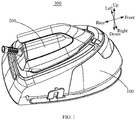
FIG. 1 is a schematic structural diagram of an iron device according to an embodiment of this application; -
FIG. 2 is a schematic structural diagram of an iron base inFIG. 1 ; -
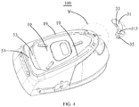
FIG. 3 is a schematic diagram of an assembly structure of the iron base inFIG. 2 and an iron when the clamping mechanism is at an open position; -
FIG. 4 is a schematic diagram of a split structure of the iron base inFIG. 2 ; -
FIG. 5 is an enlarged schematic diagram of a structure at V inFIG. 4 ; -
FIG. 6 is a schematic structural diagram of a positioning boss inFIG. 4 after a button is removed; -
FIG. 7 is a schematic structural diagram of the positioning boss inFIG. 4 from another perspective; -
FIG. 8 is a schematic structural diagram of the iron base inFIG. 4 after further splitting a limiting projection and the button; and -
FIG. 9 is an enlarged schematic structural diagram at IX inFIG. 8 . -
[Table 1] No. Reference numeral No. Reference numeral 100 Iron base 3133 Second buckle hole 10 Iron placing surface 315 Button 11 First mounting groove 3151 Abutting portion 111 Limiting projection 3153 Second buckle 1111 First buckle 317 Rotating shaft hole 113 First elastic member 3171 Accommodating groove 13 Positioning post 319 Receiving cavity 15 Stop rib 3191 Receiving groove 17 Rotating shaft hole 3193 Second elastic member 171 Mounting post 33 Positioning baffle 19 Second limiting boss 35 Buckle block 191 Buckle groove 50 Fixing portion 30 Clamping mechanism 50a Limiting space 30a Positioning space 51 First limiting boss 31 Positioning boss 53 Limiting baffle 311 Limiting groove 70 Iron placing groove 313 Second mounting groove 200 Iron 3131 Avoiding opening 300 Iron device - The implementation, functional characteristics and advantages of this application will be further described in conjunction with the embodiments and with reference to the drawings.
- The technical solutions in the embodiments of this application will be described clearly and completely in conjunction with the drawings in the embodiments of this application. Obviously, the described embodiments are only a part of the embodiments of this application, but not all the embodiments. Based on the embodiments of this application, all other embodiments obtained by a person of ordinary skill in the art without making creative efforts fall within the protection scope of this application.
- It should be noted that all the directional indicators (such as up, down, left, right, front, back, etc.) in the embodiments of this application are only used to explain the relative positional relationship, movement conditions, etc. between the components in a certain posture (as shown in the drawings). If the specific posture changes, the directional indication changes accordingly.
- In addition, descriptions related to "first", "second", etc. in this application are for descriptive purposes only, and cannot be understood as indicating or implying their relative importance or implicitly indicating the number of technical features indicated. Thus, the features defined with "first" and "second" may include at least one of the features either explicitly or implicitly. In the description of this application, the meaning of "plurality" is at least two, such as two, three, etc., unless specifically defined otherwise.
- In this application, unless otherwise clearly specified and defined, the terms "connected" and "fixed" should be understood in a broad sense. For example, "fixed" may be a fixed connection, a detachable connection, or integrated; it may be a mechanical connection or an electrical connection; it may be directly connected or indirectly connected through an intermediary; it may be the connection between two elements or the interaction between two elements, unless otherwise clearly defined. Those of ordinary skill in the art can understand the specific meanings of the above terms in this application according to specific situations.
- In addition, the technical solutions between the various embodiments of this application can be combined with each other, but it must be based on the ability of ordinary skilled in the art to achieve, when the combination of technical solutions contradicts each other or cannot be realized, this combination of technical solutions should be considered to be not exist nor fall within the protection scope claimed by this application.
- This application provides an
iron base 100. - As shown in
FIGS. 1 to 3 , theiron base 100 of this application is applied to aniron device 300, and theiron device 300 includes aniron base 100 and aniron 200 placed on theiron base 100. Aniron placing surface 10 is defined on an upper end of theiron base 100. A fixingportion 50 configured for clamping a rear end of theiron 200 is provided at a rear portion of theiron placing surface 10, and aclamping mechanism 30 is rotatably connected with a front portion of theiron placing surface 10. Theclamping mechanism 30 may rotate relative to theiron placing surface 10 and has an open position and a clamping position, and theclamping mechanism 30 may clamp a front end of theiron 200 when theclamping mechanism 30 is at the clamping position. - In this embodiment, the
iron base 100 is placed horizontally, and a flat surface on which theiron 200 is placed is formed on the upper end thereof, that is, theiron placing surface 10. Theiron placing surface 10 is provided with a fixingportion 50 and aclamping mechanism 30. The fixingportion 50 is located at the rear portion of theiron placing surface 10 and configured to clamp and fix the rear end of theiron 200. Accordingly, theclamping mechanism 30 is located at the front portion of theiron placing surface 10 and configured to clamp and fix the front end of theiron 200. Further, theclamping mechanism 30 and theiron placing surface 10 are rotatably connected. Theclamping mechanism 30 may rotate relative to theiron placing surface 10 and have an open position and a clamping position. When theclamping mechanism 30 is in the clamping position, theclamping mechanism 30 may clamp and fix the front end of theiron 200. At this time, the fixingportion 50 may clamp and fix the rear end of theiron 200, so that both the front end and the rear end of theiron 200 may be clamped and fixed, and theiron 200 may be stably placed on theiron placing surface 10. That is, the stability of theiron 200 placed on theiron base 100 is effectively improved, thereby effectively preventing theiron 200 from falling off theiron base 100, and improving the use safety of theiron device 300. When theclamping mechanism 30 rotates relative to theiron placing surface 10 from the clamping position to the open position, theclamping mechanism 30 may open the front end of theiron 200, that is, theclamping mechanism 30 may no longer clamp and fix the front end of theiron 200, and theiron 200 may be easily removed and used by lifting the front end and removing the rear end from the fixingportion 50, which is simple, convenient and reliable. - Therefore, it can be understood that, according to the technical solution of this application, the fixing
portion 50 and theclamping mechanism 30 are provided on theiron placing surface 10 of theiron base 100. The fixingportion 50 is disposed at the rear portion of theiron placing surface 10 and clamps the rear end of theiron 200. Theclamping mechanism 30 is disposed at the front portion of theiron placing surface 10 and clamps the front end of theiron 200. In this way, when theiron 200 is placed on theiron placing surface 10 of theiron base 100, the fixingportion 50 and theclamping mechanism 30 may respectively clamp and fix the rear end and the front end of theiron 200, which effectively improves the stability of theiron 200 placed on theiron base 100, thereby effectively preventing theiron 200 from falling off theiron base 100 and improving the safety of theiron device 300. - Moreover, according to the technical solution of this application, the
clamping mechanism 30 and theiron placing surface 10 are rotatably connected, and theclamping mechanism 30 may rotate relative to theiron placing surface 10 to have an open position and a clamping position. Theclamping mechanism 30 clamps the front end of the iron when theclamping mechanism 30 is at the clamping position. In this way, the clamping and loosening of the front end of theiron 200 may be easily achieved through the rotation of theclamping mechanism 30, so that the process of placing and fixing theiron 200 and the process of loosening and removing theiron 200 are simple, convenient, and reliable. - At the same time, the above structure is not only convenient for manufacturing, but also conducive to mounting and assembly, so that production efficiency and assembly efficiency may be effectively improved.
- As shown in
FIG.2 and FIG. 3 , theclamping mechanism 30 includes apositioning boss 31 and apositioning baffle 33. Thepositioning boss 31 is rotatably connected to the front portion of theiron placing surface 10, and thepositioning baffle 33 is provided at an end portion of thepositioning boss 31 away from theiron placing surface 10. Thepositioning boss 31 is opposite to the fixingportion 50 when thepositioning boss 31 is at the clamping position, and thepositioning baffle 33 extends toward the fixingportion 50 when thepositioning baffle 33 is at the clamping position. Thepositioning baffle 33, thepositioning boss 31 and theiron placing surface 10 enclose together to define apositioning space 30a for receiving the front end of theiron 200. In this way, when theiron 200 is placed on theiron placing surface 10 of theiron base 100, the front end of theiron 200 may be received and clamped in thepositioning space 30a. In this way, not only the clamping and fixing of the front end of theiron 200 by theclamping mechanism 30 can be effectively secured, and the reliability is high, but also the structure is simple and the manufacturing is convenient. - As shown in
FIGS. 2 to 4 andFIG. 7 , thepositioning boss 31 includes two ends extending along a profile extension direction of the front portion of theiron placing surface 10 when thepositioning boss 31 is at the clamping position. One end is rotatably connected with the front portion of theiron placing surface 10, and the other end defines a limitinggroove 311 on a surface facing theiron placing surface 10. Theiron placing surface 10 is further provided with a limitingprojection 111 at the front portion, and the limitingprojection 111 is clamped in the limitinggroove 311. - In this embodiment, the
positioning boss 31 may be rotated around the end that is connected to the front portion of theiron placing surface 10, and when thepositioning boss 31 is rotated from the open position to the clamping position (from outside to inside), the limitingprojection 111 on theiron placing surface 10 is received and clamped the limitinggroove 311 on thepositioning boss 31. At this time, both ends of thepositioning boss 31 are limited and fixed, and the front end of theiron 200 may be received, clamped and fixed in thepositioning space 30a defined by thepositioning baffle 33, thepositioning boss 31, and theiron placing surface 10 enclosing together, so as to realize the clamping and fixing of the front end of theiron 200. It can be understood that the cooperation of the limitingprojection 111 and the limitinggroove 311 may effectively guarantee the stability of thepositioning space 30a defined by thepositioning baffle 33, thepositioning boss 31, and theiron placing surface 10 enclosing together. Therefore, the reliability of theiron base 100 for clamping and fixing the front end of theiron 200 is improved, thereby effectively improving the stability of theiron 200 placed on theiron base 100. - As shown in
FIGS. 2 to 4 ,8 and 9 , theiron placing surface 10 further defines a first mountinggroove 11 at the front portion, and a lower end of the limitingprojection 111 is received in the first mountinggroove 11. A firstelastic member 113 is provided between a bottom wall of the first mountinggroove 11 and the limitingprojection 111, one end of the firstelastic member 113 abuts against the bottom wall of the first mountinggroove 11, and the other end of the firstelastic member 113 abuts against a surface of the limitingprojection 111 facing the bottom wall of the first mountinggroove 11. - In this embodiment, a first buckle hole 115 is further defined on the bottom wall of the first mounting
groove 11, and afirst buckle 1111 is formed in the first buckle hole 115 at the lower end of the limitingprojection 111. Moreover, the firstelastic member 113 is a compression spring, a lower end of the compression spring abuts against the bottom wall of the first mountinggroove 11, and an upper end of the compression spring abuts against the surface of the limitingprojection 111 facing the bottom wall of the first mountinggroove 11 to provide an upward abutment force (restoring force after compression) to the limitingprojection 111, so as to make the limitingprojection 111 have a movement tendency away from the bottom wall of the first mountinggroove 11. At this time, thefirst buckle 1111 is buckled with the hole wall of the first buckle hole 115 away from the opening of the first mountinggroove 11, so as to prevent the limitingprojection 111 from detaching from the first mountinggroove 11. - Specifically, when the upper end of the limiting
projection 111 is pressed, the limitingprojection 111 moves downward (into the first mounting groove 11), so that the compression spring is further compressed, and thefirst buckle 1111 is separated from the hole wall of the first buckle hole 115 away from the opening of the first mountinggroove 11 to move downward, until the upper end of the limitingprojection 111 is flush with theiron placing surface 10. In this process, the lower end surface of the positioning boss 31 (the surface facing the iron placing surface 10) rotates along theiron placing surface 10 from the open position to the clamping position (from the outside to the inside), so that the limitinggroove 311 on thepositioning boss 31 is aligned and in communication with the first mountinggroove 11 on theiron placing surface 10. At this time, the upper end of the limitingprojection 111 loses pressure, the compression spring loses pressure and extends, driving the limitingprojection 111 to move upward (toward the limiting groove 311); thefirst buckle 1111 moves upward in the first buckle hole 115 until it buckles with the hole wall of the first buckle hole 115 away from the opening of the first mounting groove 11 (to prevent the limitingprojection 111 from detaching from the first mounting groove 11), the limitingprojection 111 returns to the initial position, that is, the upper end of the limitingprojection 111 protrudes out of theiron placing surface 10. At this time, the upper end of the limitingprojection 111 is received and clamped into the limitinggroove 311 to realize the limiting and fixing of the end of thepositioning boss 31 that is not rotatably connected with the front portion of theiron placing surface 10. - In this way, the limiting
projection 111 may protrude out and draw back relative to theiron placing surface 10, so that the clamping and detaching processes of the limitingprojection 111 and the limitinggroove 311 may be more simple, reliable, and efficient, making the switching process of theclamping mechanism 30 between the open position and the clamping position be simple, reliable, and efficient, which improves the convenience of operation. - Moreover, it can be understood that the arrangement of the
first buckle 1111 and the first buckle hole 115 may, on the one hand, play the role of limiting the maximum position of the movement of the limitingprojection 111 to prevent the limitingprojection 111 from detaching from the first mountinggroove 11 to ensure the effectiveness of the structure and improve the stability of the cooperation between the limitingprojection 111 and the limitinggroove 311, on the other hand, it may further effectively improve the motion stability of the limitingprojection 111, making the related process more smoothly. - In addition, it should be noted that a guide slope provided on the limiting
projection 111 may also be configured for the application of pressure to the upper end of the limitingprojection 111 or the release of the pressure on the upper end of the limitingprojection 111, thereby effectively alleviating the extrusion between components to avoid structural damage. - Please further refer to
FIG. 5 andFIG. 6 , an end of thepositioning boss 31 not rotatably connected to the front portion of theiron placing surface 10 defines asecond mounting groove 313, and the second mountinggroove 313 is defined on a surface of thepositioning boss 31 away from theiron placing surface 10. Theclamping mechanism 30 further includes abutton 315 provided in the second mountinggroove 313, and a bottom wall of the second mountinggroove 313 defines an avoidingopening 3131 in communication with the limitinggroove 311. An abuttingportion 3151 protrudes from a lower end of thebutton 315, and the abuttingportion 3151 passes through the avoidingopening 3131 and abut against an upper end of the limitingprojection 111 when the abuttingportion 3151 is at the clamping position. - In this embodiment, a
second buckle hole 3133 is further defined on the bottom wall of the second mountinggroove 313, and asecond buckle 3153 is formed in thesecond buckle hole 3133 at the lower end of thebutton 315. Specifically, when theclamping mechanism 30 is in the clamping position, the upper end of the limitingprojection 111 protrudes out of theiron placing surface 10, and the upper end of the limitingprojection 111 is received and clamped in the limitinggroove 311. At this time, the upper end of the limitingprojection 111 abuts against the abuttingportion 3151 at the lower end of thebutton 315, and the limitingprojection 111 provides thebutton 315 an upward abutment force through the abuttingportion 3151, so as to make thebutton 315 have a movement tendency away from the bottom wall of the second mountinggroove 313. At this time, thesecond buckle 3153 is buckled with the hole wall of thesecond buckle hole 3133 away from the opening of the second mountinggroove 313, so as to prevent thebutton 315 from detaching from the second mountinggroove 313. When thebutton 315 is pressed, thebutton 315 moves downward (toward the bottom of the second mounting groove 313). Thebutton 315 applies pressure to the upper end of the limitingprojection 111 through the abuttingportion 3151, so that the limitingprojection 111 moves downward (into the first mounting groove 11) until the upper end of the limitingprojection 111 is flush with theiron placing surface 10. In this process, the lower end surface of the positioning boss 31 (the surface facing the iron placing surface 10) rotates along theiron placing surface 10 from the clamping position to the open position (from inside to outside) until the limitingprojection 111 is separated from the limitinggroove 311 and is exposed on theiron placing surface 10. At this time, theclamping mechanism 30 opens the front end of theiron 200, that is, the clamping and fixing effect of theclamping mechanism 30 on the front end of theiron 200 disappears, and theiron 200 may be removed. - In this way, the
button 315 may be used to effectively control the separation of the limitingprojection 111 and the limitinggroove 311, so that the clamping and detaching processes of the limitingprojection 111 and the limitinggroove 311 may be more simple, reliable, and efficient, making the switching process of theclamping mechanism 30 between the open position and the clamping position be simple, reliable, and efficient, which improves the convenience of operation. - Moreover, it can be understood that the arrangement of the
second buckle 3153 and thesecond buckle hole 3133 may, on the one hand, play the role of limiting the maximum position of the movement of the key 315 to prevent the key 315 from detaching from the second mountinggroove 313 to ensure the effectiveness of the structure, on the other hand, it may further effectively improve the motion stability of the key 315, making the related process more smoothly. - In addition, it should be noted that, according to actual needs, an elastic member may be added between the bottom wall of the second mounting
groove 313 and the surface of thebutton 315 facing the bottom wall of the second mountinggroove 313. One end of the elastic member abuts against the bottom wall of the second mountinggroove 313, and the other end of the elastic member abuts against the surface of thebutton 315 facing the bottom wall of the second mountinggroove 313 to provide thebutton 315 an upward abutment force (recovery force after pressing), so that thebutton 315 is always in a pressable state, thus improving the convenience of operation. - As shown in
FIGS. 4 ,5 and7 , the surface of thepositioning boss 31 facing theiron placing surface 10 further defines a receiving cavity 319. Astop rib 15 is protruded from the front portion of theiron placing surface 10 and received in the receiving cavity 319. Theclamping mechanism 30 further includes a secondelastic member 3193 received in the receiving cavity 319, one end of the secondelastic member 3193 abuts against thestop rib 15, and the other end of the secondelastic member 3193 abuts against an inner wall of the receiving cavity 319, so as to drive theclamping mechanism 30 to rotate from the clamping position to the open position. - Specifically, a
positioning post 13 is protruded from the front portion of theiron placing surface 10, and thepositioning post 13 is received in the receiving cavity 319. The secondelastic member 3193 is a torsion spring, and the ring of the torsion spring is sleeved on thepositioning post 13. At this time, the inner wall surface of the receiving cavity 319 further defines a receivinggroove 3191, the torsion spring is in a tightened state, one end of the torsion spring abuts against thestop rib 15, and the other end of the torsion spring is received in the receivinggroove 3191 and abuts against the groove wall of the receivinggroove 3191. The torsion spring has a tendency to extend, that is, the two ends of the torsion spring have a tendency to move away from each other to drive theclamping mechanism 30 to rotate toward the open position. In this way, when the limitingprojection 111 and the limitinggroove 311 are separated, the secondelastic member 3193 may drive theclamping mechanism 30 to rotate to the open position, so that the switching process of theclamping mechanism 30 between the open position and the clamping position may be simple, reliable, and efficient, which improves the convenience of operation. - As shown in
FIG. 4 ,FIG. 5 andFIG. 7 , theiron placing surface 10 defines arotating shaft hole 17 at the front portion, arotating shaft 317 is protruded from an end of thepositioning boss 31 not defining the limitinggroove 311 toward therotating shaft hole 17, and therotating shaft 317 is inserted into therotating shaft hole 17. Such a structural arrangement may not only effectively improve the stability of the rotational connection between theclamping mechanism 30 and theiron placing surface 10, but also improve the rotational stability of theclamping mechanism 30, and has a simple and reliable structure, and is convenient and efficient to manufacture and assemble. - In addition, in this embodiment, the end surface of the
rotating shaft 317 away from thepositioning boss 31 further defines anaccommodating groove 3171. A mountingpost 171 is further protruded from the bottom wall of therotating shaft hole 17 and is inserted into theaccommodating groove 3171, so as to further enhance the stability of the rotation connection between theclamping mechanism 30 and theiron placing surface 10, to improve the stability of the rotation of theclamping mechanism 30, and to ensure the effectiveness of the relevant structure. - In addition, it should be noted that in this embodiment, the
positioning boss 31 is composed of an upper cover body and a lower cover body being engaged, and the upper and lower cover bodies further define a connecting hole respectively, and the stability of the connection between the upper and lower cover bodies is enhanced by the cooperation of a fastener and the two connecting holes. Further, the limitinggroove 311 is defined on the surface of the lower cover body facing theiron placing surface 10, and the second mountinggroove 313 is defined on the surface of the upper cover body away from theiron placing surface 10. One end of therotating shaft 317 is fixed between the upper and lower cover bodies, and the other end of therotating shaft 317 is configured to penetrate the surface of the lower cover body facing theiron placing surface 10 and be inserted into therotating shaft hole 17 of theiron placing surface 10. At this time, the mountingpost 171 in therotating shaft hole 17 is inserted into theaccommodating groove 3171 of therotating shaft 317. The receiving cavity 319 is also defined on the surface of the lower cover body facing theiron placing surface 10 and between the two ends of thepositioning boss 31. It can be understood that, in some other embodiments, thepositioning boss 31 may also be set to another effective form according to actual conditions, so as to better meet the requirements of manufacturing, mounting, and actual use. - As shown in
FIGS. 1 ,2 ,4 , and8 , the fixingportion 50 includes a first limitingboss 51 and a limitingbaffle 53. The first limitingboss 51 is provided at the rear portion of theiron placing surface 10, the limitingbaffle 53 is provided at an end portion of the first limitingboss 51 away from theiron placing surface 10, and the limitingbaffle 53 extends toward the front portion of theiron placing surface 10. The limitingbaffle 53, the first limitingboss 51 and theiron placing surface 10 enclose together to define a limitingspace 50a for receiving the rear end of theiron 200. - In this embodiment, the rear portion of the
iron placing surface 10 is provided with a first limitingboss 51 which extends along the profile extension direction of the rear portion of theiron placing surface 10 and is generally elongated. Moreover, an end of the first limitingboss 51 away from theiron placing surface 10 is provided with a limitingbaffle 53 which extends toward the front portion of theiron placing surface 10 and is opposite to theiron placing surface 10. At this time, the limitingbaffle 53, the first limitingboss 51, and theiron placing surface 10 enclose together to define a limitingspace 50a. When theiron 200 is placed on theiron placing surface 10 of theiron base 100, the rear end of theiron 200 may be received and clamped in the limitingspace 50a. In this way, not only the clamping and fixing of the rear end of theiron 200 by the fixingportion 50 can be effectively secured, and the reliability is high, but also the structure is simple and the manufacturing is convenient. - As shown in
FIGS. 1 to 3 , one second limitingboss 19 respectively protrudes from each of two side portions of theiron placing surface 10, and the second limitingboss 19 extends along a profile extension direction of the corresponding side portion. In this way, when theiron 200 is placed on theiron placing surface 10 of theiron base 100, the two second limitingbosses 19 may play the role of limiting and fixing the two sides of theiron 200 respectively, thereby further effectively improving the stability of theiron 200 placed on theiron base 100, so as to effectively prevent theiron 200 from falling off theiron base 100 and improve the safety of use of theiron device 300. - Further, an end of the each second limiting
boss 19 facing the first limitingboss 51 is connected to the first limitingboss 51, and an end of the second limitingboss 19 facing theclamping mechanism 30 abuts against theclamping mechanism 30. Theiron placing surface 10, the first limitingboss 51, theclamping mechanism 30, and two second limitingbosses 19 enclose together to define aniron placing groove 70. - In this embodiment, the two second limiting
bosses 19 and the first limitingboss 51 have an integrated structure, and specifically, they can be manufactured by integral injection molding. Moreover, when theclamping mechanism 30 is in the clamping position, theclamping mechanism 30 has two ends extending along the profile extension direction of the front portion of theiron placing surface 10, and the two ends abut against the two second limitingbosses 19 respectively. At this time, theiron placing surface 10, the first limitingboss 51, theclamping mechanism 30, and the two second limitingbosses 19 enclose together to define aniron placing groove 70. When theiron 200 is placed on theiron placing surface 10 of theiron base 100, the lower end of theiron 200 may be received, clamped and fixed in theiron placing groove 70. In this way, the periphery of theiron 200 may be limited and fixed, and the stability of theiron 200 placed on theiron base 100 is further effectively improved. - In addition, a
buckle block 35 is protruded from the end of theclamping mechanism 30 that is not rotatably connected to the front portion of theiron placing surface 10 toward the end of the corresponding second limitingboss 19. At this time, abuckle groove 191 is defined at the end of the corresponding second limitingboss 19. When theclamping mechanism 30 is at the clamping position, thebuckle block 35 is clamped into thebuckle groove 191, so that the stability of theclamping mechanism 30 is enhanced, and the clamping effect of theclamping mechanism 30 on the front end of theiron 200 is enhanced. Therefore, the stability of theiron 200 placed on theiron base 100 is enhanced. - This application further provides an
iron device 300, which includes aniron 200 and aniron base 100 as described above. For the specific structure of theiron base 100, see the foregoing embodiment for details. Since theiron device 300 adopts all the technical solutions of all the foregoing embodiments, it has at least all the beneficial effects brought about by all the technical solutions of all the foregoing embodiments, which will not be repeated here. - Where, the
iron 200 is placed on theiron placing surface 10 of theiron base 100, the fixingportion 50 of theiron base 100 clamps the rear end of theiron 200, and theclamping mechanism 30 clamps the front end of theiron 200 when theclamping mechanism 30 is at the clamping position. - The above is only preferred embodiments of this application, and thus does not limit the scope of this application, and the equivalent structural transformation made by the content of the specification and the drawings of this application, or directly/indirectly applied to other related technical fields are all included in the patent protection scope of this application.
Claims (20)
- An iron base, characterized in that, an iron placing surface is provided on an upper end of the iron base, a fixing portion configured for clamping a rear end of an iron is provided at a rear portion of the iron placing surface, a clamping mechanism is configured to be rotatably connected with a front portion of the iron placing surface, the clamping mechanism is configured to rotate relative to the iron placing surface and has an open position and a clamping position, and the clamping mechanism is configured to clamp a front end of the iron when the clamping mechanism is at the clamping position.
- The iron base according to claim 1, characterized in that, the clamping mechanism comprises a positioning boss and a positioning baffle, the positioning boss is configured to be rotatably connected to the front portion of the iron placing surface, the positioning baffle is provided at an end portion of the positioning boss away from the iron placing surface, the positioning boss is configured to be opposite to the fixing portion when the positioning boss is at the clamping position, the positioning baffle is configured to extend toward the fixing portion when the positioning baffle is at the clamping position, wherein the positioning baffle, the positioning boss and the iron placing surface enclose a positioning space for receiving the front end of the iron.
- The iron base according to claim 2, characterized in that, the fixing portion comprises a first limiting boss and a limiting baffle, the first limiting boss is provided at the rear portion of the iron placing surface, the limiting baffle is provided at an end portion of the first limiting boss away from the iron placing surface, the limiting baffle is configured to extend toward the front portion of the iron placing surface, wherein the limiting baffle, the first limiting boss and the iron placing surface enclose a limiting space for receiving the rear end of the iron.
- The iron base according to claim 3, characterized in that, one second limiting boss respectively protrudes from each of two side portions of the iron placing surface, and second limiting boss is configured to extend along a profile extension direction of the corresponding side portion.
- The iron base according to claim 4, characterized in that, an end of the second limiting boss facing the first limiting boss is connected to the first limiting boss, an end of the second limiting boss facing the clamping mechanism abuts against the clamping mechanism, wherein, the iron placing surface, the first limiting boss, the clamping mechanism, and two second limiting bosses enclose an iron placing groove.
- The iron base according to claim 2, characterized in that, the positioning boss comprises two ends extending along a profile extension direction of the front portion of the iron placing surface when the positioning boss is at the clamping position, one end is rotatably connected with the front portion of the iron placing surface, the other end is provided with a limiting groove on a surface facing the iron placing surface, the iron placing surface is further provided with a limiting projection at the front portion, and the limiting projection is clamped in the limiting groove.
- The iron base according to claim 6, characterized in that, the iron placing surface is further provided with a first mounting groove at the front portion, a lower end of the limiting projection is received in the first mounting groove, a first elastic member is provided between a bottom wall of the first mounting groove and the limiting projection, one end of the first elastic member abuts against the bottom wall of the first mounting groove, and the other end of the first elastic member abuts against a surface of the limiting projection facing the bottom wall of the first mounting groove.
- The iron base according to claim 7, characterized in that, an end of the positioning boss not rotatably connected to the front portion of the iron placing surface is provided with a second mounting groove, the second mounting groove is arranged on a surface of the positioning boss away from the iron placing surface, the clamping mechanism further comprises a button provided in the second mounting groove, a bottom wall of the second mounting groove is provided with an avoiding opening in communication with the limiting groove , an abutting portion protrudes from a lower end of the button, and the abutting portion passes through the avoiding opening and abuts against an upper end of the limiting projection when the abutting portion is at the clamping position.
- The iron base according to claim 8, characterized in that, a surface of the positioning boss facing the iron placing surface is further provided with a receiving cavity, a stop rib protrudes from the front portion of the iron placing surface and is received in the receiving cavity, the clamping mechanism further comprises a second elastic member received in the receiving cavity, one end of the second elastic member abuts against the stop rib, and the other end of the second elastic member abuts against an inner wall of the receiving cavity to drive the clamping mechanism to rotate from the clamping position to the open position.
- The iron base according to claim 9, characterized in that, the fixing portion comprises a first limiting boss and a limiting baffle, the first limiting boss is configured to be provided at the rear portion of the iron placing surface, the limiting baffle is configured to be provided at an end portion of the first limiting boss facing away from the iron placing surface, the limiting baffle is configured to extend toward the front portion of the iron placing surface, and the limiting baffle, the first limiting boss and the iron placing surface are configured to enclose together to define a limiting space for receiving the rear end of the iron.
- The iron base according to claim 6, characterized in that, the front portion of the iron placing surface is provided with a rotating shaft hole, a rotating shaft is arranged on an end of the positioning boss, which is not provided with the limiting groove and protrudes toward the rotating shaft hole, and the rotating shaft is inserted into the rotating shaft hole.
- The iron base according to claim 1, characterized in that, the fixing portion comprises a first limiting boss and a limiting baffle, the first limiting boss is configured to be provided at the rear portion of the iron placing surface, the limiting baffle is configured to be provided at an end portion of the first limiting boss facing away from the iron placing surface, the limiting baffle is configured to extend toward the front portion of the iron placing surface, and the limiting baffle, the first limiting boss and the iron placing surface are configured to enclose together to define a limiting space for receiving the rear end of the iron
- The iron base according to claim 12, characterized in that, one second limiting boss is configured to be protruded from each of two side portions of the iron placing surface, and each second limiting boss is configured to extend along a profile extension direction of a corresponding side portion.
- The iron base according to claim 13, characterized in that, an end of the each second limiting boss facing the first limiting boss is configured to be connected to the first limiting boss, an end of the each second limiting boss facing the clamping mechanism is configured to abut against the clamping mechanism, and the iron placing surface, the first limiting boss, the clamping mechanism, and two second limiting bosses are configured to enclose together to define an iron placing groove.
- An iron device, characterized by comprising an iron and an iron base, an iron placing surface is configured to be defined on an upper end of the iron base, a fixing portion configured for clamping a rear end of the iron is configured to be provided at a rear portion of the iron placing surface, a clamping mechanism is configured to be rotatably connected with a front portion of the iron placing surface, the clamping mechanism is configured to rotate relative to the iron placing surface and having an open position and a clamping position, the clamping mechanism is configured to clamp a front end of the iron when the clamping mechanism is at the clamping position, wherein the iron is placed on the iron placing surface of the iron base, the fixing portion of the iron base clamps a rear end of the iron, and the clamping mechanism of the iron base clamps the front end of the iron when the clamping mechanism is at the clamp position.
- The iron base according to claim 15, characterized in that, the clamping mechanism comprises a positioning boss and a positioning baffle, the positioning boss is configured to be rotatably connected to the front portion of the iron placing surface, the positioning baffle is configured to be provided at an end portion of the positioning boss facing away from the iron placing surface, the positioning boss is configured to be opposite to the fixing portion when the positioning boss is at the clamping position, the positioning baffle is configured to extend toward the fixing portion when the positioning baffle is at the clamping position, and the positioning baffle, the positioning boss and the iron placing surface are configured to enclose together to define a positioning space for receiving the front end of the iron.
- The iron base according to claim 16, characterized in that, the positioning boss comprises two ends extending along a profile extension direction of the front portion of the iron placing surface when he positioning boss is at the clamping position, one end is configured to be rotatably connected with the front portion of the iron placing surface, the other end is configured to define a limiting groove on a surface facing the iron placing surface, the iron placing surface is further provided with a limiting projection at the front portion, and the limiting projection is configured to be clamped in the limiting groove.
- The iron base according to claim 17, characterized in that, the iron placing surface further defines a first mounting groove at the front portion, a lower end of the limiting projection is configured to be received in the first mounting groove, a first elastic member is configured to be provided between a bottom wall of the first mounting groove and the limiting projection, one end of the first elastic member is configured to abut against the bottom wall of the first mounting groove, and the other end of the first elastic member is configured to abut against a surface of the limiting projection facing the bottom wall of the first mounting groove.
- The iron base according to claim 18, characterized in that, an end of the positioning boss not rotatably connected to the front portion of the iron placing surface is configured to define a second mounting groove, the second mounting groove is configured to be defined on a surface of the positioning boss facing away from the iron placing surface, the clamping mechanism further comprises a button provided in the second mounting groove, the second mounting groove is configured to define an avoiding opening in communication with the limiting groove on a bottom wall, an abutting portion is configured to be protruded from a lower end of the button, and the abutting portion is configured to pass through the avoiding opening and abut against an upper end of the limiting projection when the abutting portion is at the clamping position.
- The iron base according to claim 15, characterized in that, the fixing portion comprises a first limiting boss and a limiting baffle, the first limiting boss is configured to be provided at the rear portion of the iron placing surface, the limiting baffle is configured to be provided at an end portion of the first limiting boss facing away from the iron placing surface, the limiting baffle is configured to extend toward the front portion of the iron placing surface, and the limiting baffle, the first limiting boss and the iron placing surface are configured to enclose together to define a limiting space for receiving the rear end of the iron.
Applications Claiming Priority (2)
| Application Number | Priority Date | Filing Date | Title |
|---|---|---|---|
| CN201711306649.6A CN107904907B (en) | 2017-12-07 | 2017-12-07 | Iron base and iron equipment |
| PCT/CN2017/118387 WO2019109411A1 (en) | 2017-12-07 | 2017-12-25 | Clothes iron base and clothes iron device |
Publications (3)
| Publication Number | Publication Date |
|---|---|
| EP3722496A4 EP3722496A4 (en) | 2020-10-14 |
| EP3722496A1 true EP3722496A1 (en) | 2020-10-14 |
| EP3722496B1 EP3722496B1 (en) | 2022-03-02 |
Family
ID=61854122
Family Applications (1)
| Application Number | Title | Priority Date | Filing Date |
|---|---|---|---|
| EP17934209.2A Active EP3722496B1 (en) | 2017-12-07 | 2017-12-25 | Clothes iron base and clothes iron device |
Country Status (3)
| Country | Link |
|---|---|
| EP (1) | EP3722496B1 (en) |
| CN (1) | CN107904907B (en) |
| WO (1) | WO2019109411A1 (en) |
Families Citing this family (7)
| Publication number | Priority date | Publication date | Assignee | Title |
|---|---|---|---|---|
| CN114311979B (en) | 2017-08-01 | 2024-12-06 | 克里卡特股份有限公司 | Heat Press |
| CN110230181B (en) * | 2018-03-05 | 2021-06-01 | 漳州灿坤实业有限公司 | Iron device and base locking mechanism thereof |
| FR3085046B1 (en) * | 2018-08-20 | 2020-07-31 | Seb Sa | IRONING APPLIANCE INCLUDING AN IRON AND A PORTABLE BASE EQUIPPED WITH A PIVOTING HANDLE |
| MX2022001983A (en) | 2019-08-18 | 2022-05-18 | Cricut Inc | Heat press, components, apparatuses, systems, and methods. |
| US11707104B1 (en) | 2022-03-03 | 2023-07-25 | Cricut, Inc. | Heat press apparatuses, systems, and methods |
| USD1109956S1 (en) * | 2024-11-07 | 2026-01-20 | Maowu Hu | Steam cleaner |
| USD1111271S1 (en) * | 2024-12-24 | 2026-02-03 | Shenzhen AIWASIJI Internet Technology Co., Ltd. | Steam cleaner |
Family Cites Families (15)
| Publication number | Priority date | Publication date | Assignee | Title |
|---|---|---|---|---|
| FR2874628B1 (en) * | 2004-09-02 | 2006-12-22 | Seb Sa | IRONING APPARATUS COMPRISING AN IRON AND A PORTABLE BASE |
| CN201627099U (en) * | 2010-01-28 | 2010-11-10 | 广东新宝电器股份有限公司 | Electric iron with steam seat |
| CN202090209U (en) * | 2011-01-14 | 2011-12-28 | 张平 | Steam iron with base |
| DE102011080152B4 (en) * | 2011-05-31 | 2014-05-15 | BSH Bosch und Siemens Hausgeräte GmbH | Base for an ironing station and ironing station |
| CN202247462U (en) * | 2011-09-05 | 2012-05-30 | 宁波爱佳电器有限公司 | Brake structure of electric iron table seat |
| CN203096475U (en) * | 2012-12-04 | 2013-07-31 | 张建炜 | Automatic water filling electric iron |
| CN104264432B (en) * | 2012-12-04 | 2016-06-29 | 张建炜 | A kind of electric iron of automatic water-filling |
| CN104213384B (en) * | 2012-12-04 | 2017-01-25 | 张建炜 | Electric iron capable of automatically filling water |
| CN102965897B (en) * | 2012-12-04 | 2015-03-25 | 张建炜 | A self-filling electric iron |
| JP2015062624A (en) * | 2013-09-26 | 2015-04-09 | パナソニックIpマネジメント株式会社 | Ironing equipment |
| CN103614893B (en) * | 2013-11-19 | 2016-01-13 | 宁波凯波集团有限公司 | Be convenient to split type steam iron and the latch-up structure thereof of carrying |
| CN203583244U (en) * | 2013-11-19 | 2014-05-07 | 宁波凯波集团有限公司 | Split type steam iron convenient to carry and locking structure thereof |
| FR3018831B1 (en) * | 2014-03-24 | 2016-03-11 | Seb Sa | HOUSEHOLD APPLIANCE COMPRISING A DEVICE FOR IRONING AND / OR THREADING TO BE HAND HELD AND A PORTABLE BASE |
| DE102014211099B4 (en) * | 2014-06-11 | 2017-10-26 | De'longhi Braun Household Gmbh | Device for locking a steam iron |
| CN204715095U (en) * | 2015-01-20 | 2015-10-21 | 东保集团有限公司 | Iron and locking device |
-
2017
- 2017-12-07 CN CN201711306649.6A patent/CN107904907B/en active Active
- 2017-12-25 WO PCT/CN2017/118387 patent/WO2019109411A1/en not_active Ceased
- 2017-12-25 EP EP17934209.2A patent/EP3722496B1/en active Active
Also Published As
| Publication number | Publication date |
|---|---|
| CN107904907B (en) | 2019-10-01 |
| CN107904907A (en) | 2018-04-13 |
| EP3722496A4 (en) | 2020-10-14 |
| WO2019109411A1 (en) | 2019-06-13 |
| EP3722496B1 (en) | 2022-03-02 |
Similar Documents
| Publication | Publication Date | Title |
|---|---|---|
| EP3722496A1 (en) | Clothes iron base and clothes iron device | |
| CN216819881U (en) | ring holder | |
| WO2021128286A1 (en) | Electronic device and snap-on module | |
| KR100640369B1 (en) | Built-in battery pack case locking device for mobile terminals | |
| CN209266726U (en) | A kind of connector with spring reset buckle structure | |
| CN111972785A (en) | Go up end zipper device and dress | |
| US8107237B2 (en) | Electronic device with latching assembly | |
| CN103490227B (en) | Clamping device and combination thereof | |
| CN220691906U (en) | Matching structure of switch cover and panel | |
| CN219707194U (en) | Mobile electronic equipment support | |
| CN216530421U (en) | Wire casing section bar | |
| CN217306672U (en) | Battery pack disassembling and assembling structure | |
| CN223229912U (en) | Tablet Case | |
| CN115251540B (en) | A type of buckle | |
| CN219775220U (en) | Quick release base structures and vehicles | |
| CN211502502U (en) | Draw hanger and ceiling lamp | |
| CN2571019Y (en) | Tripping-proof power supply connector | |
| CN215862390U (en) | Fixing device and external member | |
| CN222915234U (en) | Wall socket | |
| CN219145887U (en) | Remote controller for electric appliance | |
| CN216624457U (en) | Battery pack with buttons not falling off from upper shell | |
| CN212725689U (en) | Five-hole socket | |
| CN220156551U (en) | Electronic equipment accessory | |
| CN219303531U (en) | Bluetooth key switch convenient to dismouting | |
| CN215680458U (en) | A kind of anti-drop mechanism for single-piece high-voltage isolating switch |
Legal Events
| Date | Code | Title | Description |
|---|---|---|---|
| STAA | Information on the status of an ep patent application or granted ep patent |
Free format text: STATUS: THE INTERNATIONAL PUBLICATION HAS BEEN MADE |
|
| PUAI | Public reference made under article 153(3) epc to a published international application that has entered the european phase |
Free format text: ORIGINAL CODE: 0009012 |
|
| STAA | Information on the status of an ep patent application or granted ep patent |
Free format text: STATUS: REQUEST FOR EXAMINATION WAS MADE |
|
| 17P | Request for examination filed |
Effective date: 20200706 |
|
| A4 | Supplementary search report drawn up and despatched |
Effective date: 20200916 |
|
| AK | Designated contracting states |
Kind code of ref document: A1 Designated state(s): AL AT BE BG CH CY CZ DE DK EE ES FI FR GB GR HR HU IE IS IT LI LT LU LV MC MK MT NL NO PL PT RO RS SE SI SK SM TR |
|
| AX | Request for extension of the european patent |
Extension state: BA ME |
|
| DAV | Request for validation of the european patent (deleted) | ||
| DAX | Request for extension of the european patent (deleted) | ||
| GRAP | Despatch of communication of intention to grant a patent |
Free format text: ORIGINAL CODE: EPIDOSNIGR1 |
|
| STAA | Information on the status of an ep patent application or granted ep patent |
Free format text: STATUS: GRANT OF PATENT IS INTENDED |
|
| RIC1 | Information provided on ipc code assigned before grant |
Ipc: D06F 75/40 20060101ALN20211117BHEP Ipc: D06F 75/12 20060101AFI20211117BHEP |
|
| INTG | Intention to grant announced |
Effective date: 20211213 |
|
| GRAS | Grant fee paid |
Free format text: ORIGINAL CODE: EPIDOSNIGR3 |
|
| GRAA | (expected) grant |
Free format text: ORIGINAL CODE: 0009210 |
|
| STAA | Information on the status of an ep patent application or granted ep patent |
Free format text: STATUS: THE PATENT HAS BEEN GRANTED |
|
| AK | Designated contracting states |
Kind code of ref document: B1 Designated state(s): AL AT BE BG CH CY CZ DE DK EE ES FI FR GB GR HR HU IE IS IT LI LT LU LV MC MK MT NL NO PL PT RO RS SE SI SK SM TR |
|
| REG | Reference to a national code |
Ref country code: GB Ref legal event code: FG4D |
|
| REG | Reference to a national code |
Ref country code: CH Ref legal event code: EP Ref country code: AT Ref legal event code: REF Ref document number: 1472315 Country of ref document: AT Kind code of ref document: T Effective date: 20220315 |
|
| REG | Reference to a national code |
Ref country code: DE Ref legal event code: R096 Ref document number: 602017054240 Country of ref document: DE |
|
| REG | Reference to a national code |
Ref country code: IE Ref legal event code: FG4D |
|
| REG | Reference to a national code |
Ref country code: LT Ref legal event code: MG9D |
|
| REG | Reference to a national code |
Ref country code: NL Ref legal event code: MP Effective date: 20220302 |
|
| PG25 | Lapsed in a contracting state [announced via postgrant information from national office to epo] |
Ref country code: SE Free format text: LAPSE BECAUSE OF FAILURE TO SUBMIT A TRANSLATION OF THE DESCRIPTION OR TO PAY THE FEE WITHIN THE PRESCRIBED TIME-LIMIT Effective date: 20220302 Ref country code: RS Free format text: LAPSE BECAUSE OF FAILURE TO SUBMIT A TRANSLATION OF THE DESCRIPTION OR TO PAY THE FEE WITHIN THE PRESCRIBED TIME-LIMIT Effective date: 20220302 Ref country code: NO Free format text: LAPSE BECAUSE OF FAILURE TO SUBMIT A TRANSLATION OF THE DESCRIPTION OR TO PAY THE FEE WITHIN THE PRESCRIBED TIME-LIMIT Effective date: 20220602 Ref country code: LT Free format text: LAPSE BECAUSE OF FAILURE TO SUBMIT A TRANSLATION OF THE DESCRIPTION OR TO PAY THE FEE WITHIN THE PRESCRIBED TIME-LIMIT Effective date: 20220302 Ref country code: HR Free format text: LAPSE BECAUSE OF FAILURE TO SUBMIT A TRANSLATION OF THE DESCRIPTION OR TO PAY THE FEE WITHIN THE PRESCRIBED TIME-LIMIT Effective date: 20220302 Ref country code: ES Free format text: LAPSE BECAUSE OF FAILURE TO SUBMIT A TRANSLATION OF THE DESCRIPTION OR TO PAY THE FEE WITHIN THE PRESCRIBED TIME-LIMIT Effective date: 20220302 Ref country code: BG Free format text: LAPSE BECAUSE OF FAILURE TO SUBMIT A TRANSLATION OF THE DESCRIPTION OR TO PAY THE FEE WITHIN THE PRESCRIBED TIME-LIMIT Effective date: 20220602 |
|
| REG | Reference to a national code |
Ref country code: AT Ref legal event code: MK05 Ref document number: 1472315 Country of ref document: AT Kind code of ref document: T Effective date: 20220302 |
|
| PG25 | Lapsed in a contracting state [announced via postgrant information from national office to epo] |
Ref country code: PL Free format text: LAPSE BECAUSE OF FAILURE TO SUBMIT A TRANSLATION OF THE DESCRIPTION OR TO PAY THE FEE WITHIN THE PRESCRIBED TIME-LIMIT Effective date: 20220302 Ref country code: LV Free format text: LAPSE BECAUSE OF FAILURE TO SUBMIT A TRANSLATION OF THE DESCRIPTION OR TO PAY THE FEE WITHIN THE PRESCRIBED TIME-LIMIT Effective date: 20220302 Ref country code: GR Free format text: LAPSE BECAUSE OF FAILURE TO SUBMIT A TRANSLATION OF THE DESCRIPTION OR TO PAY THE FEE WITHIN THE PRESCRIBED TIME-LIMIT Effective date: 20220603 Ref country code: FI Free format text: LAPSE BECAUSE OF FAILURE TO SUBMIT A TRANSLATION OF THE DESCRIPTION OR TO PAY THE FEE WITHIN THE PRESCRIBED TIME-LIMIT Effective date: 20220302 |
|
| PG25 | Lapsed in a contracting state [announced via postgrant information from national office to epo] |
Ref country code: NL Free format text: LAPSE BECAUSE OF FAILURE TO SUBMIT A TRANSLATION OF THE DESCRIPTION OR TO PAY THE FEE WITHIN THE PRESCRIBED TIME-LIMIT Effective date: 20220302 |
|
| PG25 | Lapsed in a contracting state [announced via postgrant information from national office to epo] |
Ref country code: SM Free format text: LAPSE BECAUSE OF FAILURE TO SUBMIT A TRANSLATION OF THE DESCRIPTION OR TO PAY THE FEE WITHIN THE PRESCRIBED TIME-LIMIT Effective date: 20220302 Ref country code: SK Free format text: LAPSE BECAUSE OF FAILURE TO SUBMIT A TRANSLATION OF THE DESCRIPTION OR TO PAY THE FEE WITHIN THE PRESCRIBED TIME-LIMIT Effective date: 20220302 Ref country code: RO Free format text: LAPSE BECAUSE OF FAILURE TO SUBMIT A TRANSLATION OF THE DESCRIPTION OR TO PAY THE FEE WITHIN THE PRESCRIBED TIME-LIMIT Effective date: 20220302 Ref country code: PT Free format text: LAPSE BECAUSE OF FAILURE TO SUBMIT A TRANSLATION OF THE DESCRIPTION OR TO PAY THE FEE WITHIN THE PRESCRIBED TIME-LIMIT Effective date: 20220704 Ref country code: EE Free format text: LAPSE BECAUSE OF FAILURE TO SUBMIT A TRANSLATION OF THE DESCRIPTION OR TO PAY THE FEE WITHIN THE PRESCRIBED TIME-LIMIT Effective date: 20220302 Ref country code: CZ Free format text: LAPSE BECAUSE OF FAILURE TO SUBMIT A TRANSLATION OF THE DESCRIPTION OR TO PAY THE FEE WITHIN THE PRESCRIBED TIME-LIMIT Effective date: 20220302 Ref country code: AT Free format text: LAPSE BECAUSE OF FAILURE TO SUBMIT A TRANSLATION OF THE DESCRIPTION OR TO PAY THE FEE WITHIN THE PRESCRIBED TIME-LIMIT Effective date: 20220302 |
|
| PG25 | Lapsed in a contracting state [announced via postgrant information from national office to epo] |
Ref country code: IS Free format text: LAPSE BECAUSE OF FAILURE TO SUBMIT A TRANSLATION OF THE DESCRIPTION OR TO PAY THE FEE WITHIN THE PRESCRIBED TIME-LIMIT Effective date: 20220702 Ref country code: AL Free format text: LAPSE BECAUSE OF FAILURE TO SUBMIT A TRANSLATION OF THE DESCRIPTION OR TO PAY THE FEE WITHIN THE PRESCRIBED TIME-LIMIT Effective date: 20220302 |
|
| REG | Reference to a national code |
Ref country code: DE Ref legal event code: R097 Ref document number: 602017054240 Country of ref document: DE |
|
| PLBE | No opposition filed within time limit |
Free format text: ORIGINAL CODE: 0009261 |
|
| STAA | Information on the status of an ep patent application or granted ep patent |
Free format text: STATUS: NO OPPOSITION FILED WITHIN TIME LIMIT |
|
| PG25 | Lapsed in a contracting state [announced via postgrant information from national office to epo] |
Ref country code: DK Free format text: LAPSE BECAUSE OF FAILURE TO SUBMIT A TRANSLATION OF THE DESCRIPTION OR TO PAY THE FEE WITHIN THE PRESCRIBED TIME-LIMIT Effective date: 20220302 |
|
| 26N | No opposition filed |
Effective date: 20221205 |
|
| PG25 | Lapsed in a contracting state [announced via postgrant information from national office to epo] |
Ref country code: SI Free format text: LAPSE BECAUSE OF FAILURE TO SUBMIT A TRANSLATION OF THE DESCRIPTION OR TO PAY THE FEE WITHIN THE PRESCRIBED TIME-LIMIT Effective date: 20220302 |
|
| P01 | Opt-out of the competence of the unified patent court (upc) registered |
Effective date: 20230526 |
|
| PG25 | Lapsed in a contracting state [announced via postgrant information from national office to epo] |
Ref country code: IT Free format text: LAPSE BECAUSE OF FAILURE TO SUBMIT A TRANSLATION OF THE DESCRIPTION OR TO PAY THE FEE WITHIN THE PRESCRIBED TIME-LIMIT Effective date: 20220302 |
|
| REG | Reference to a national code |
Ref country code: CH Ref legal event code: PL |
|
| REG | Reference to a national code |
Ref country code: BE Ref legal event code: MM Effective date: 20221231 |
|
| PG25 | Lapsed in a contracting state [announced via postgrant information from national office to epo] |
Ref country code: LU Free format text: LAPSE BECAUSE OF NON-PAYMENT OF DUE FEES Effective date: 20221225 |
|
| PG25 | Lapsed in a contracting state [announced via postgrant information from national office to epo] |
Ref country code: LI Free format text: LAPSE BECAUSE OF NON-PAYMENT OF DUE FEES Effective date: 20221231 Ref country code: IE Free format text: LAPSE BECAUSE OF NON-PAYMENT OF DUE FEES Effective date: 20221225 Ref country code: CH Free format text: LAPSE BECAUSE OF NON-PAYMENT OF DUE FEES Effective date: 20221231 |
|
| PG25 | Lapsed in a contracting state [announced via postgrant information from national office to epo] |
Ref country code: BE Free format text: LAPSE BECAUSE OF NON-PAYMENT OF DUE FEES Effective date: 20221231 |
|
| PG25 | Lapsed in a contracting state [announced via postgrant information from national office to epo] |
Ref country code: CY Free format text: LAPSE BECAUSE OF FAILURE TO SUBMIT A TRANSLATION OF THE DESCRIPTION OR TO PAY THE FEE WITHIN THE PRESCRIBED TIME-LIMIT Effective date: 20220302 |
|
| PG25 | Lapsed in a contracting state [announced via postgrant information from national office to epo] |
Ref country code: MK Free format text: LAPSE BECAUSE OF FAILURE TO SUBMIT A TRANSLATION OF THE DESCRIPTION OR TO PAY THE FEE WITHIN THE PRESCRIBED TIME-LIMIT Effective date: 20220302 Ref country code: HU Free format text: LAPSE BECAUSE OF FAILURE TO SUBMIT A TRANSLATION OF THE DESCRIPTION OR TO PAY THE FEE WITHIN THE PRESCRIBED TIME-LIMIT; INVALID AB INITIO Effective date: 20171225 |
|
| PG25 | Lapsed in a contracting state [announced via postgrant information from national office to epo] |
Ref country code: MC Free format text: LAPSE BECAUSE OF FAILURE TO SUBMIT A TRANSLATION OF THE DESCRIPTION OR TO PAY THE FEE WITHIN THE PRESCRIBED TIME-LIMIT Effective date: 20220302 |
|
| PG25 | Lapsed in a contracting state [announced via postgrant information from national office to epo] |
Ref country code: MC Free format text: LAPSE BECAUSE OF FAILURE TO SUBMIT A TRANSLATION OF THE DESCRIPTION OR TO PAY THE FEE WITHIN THE PRESCRIBED TIME-LIMIT Effective date: 20220302 |
|
| PG25 | Lapsed in a contracting state [announced via postgrant information from national office to epo] |
Ref country code: MT Free format text: LAPSE BECAUSE OF FAILURE TO SUBMIT A TRANSLATION OF THE DESCRIPTION OR TO PAY THE FEE WITHIN THE PRESCRIBED TIME-LIMIT Effective date: 20220302 |
|
| PGFP | Annual fee paid to national office [announced via postgrant information from national office to epo] |
Ref country code: DE Payment date: 20241216 Year of fee payment: 8 |
|
| PGFP | Annual fee paid to national office [announced via postgrant information from national office to epo] |
Ref country code: GB Payment date: 20241213 Year of fee payment: 8 |
|
| PGFP | Annual fee paid to national office [announced via postgrant information from national office to epo] |
Ref country code: FR Payment date: 20241216 Year of fee payment: 8 |
|
| PG25 | Lapsed in a contracting state [announced via postgrant information from national office to epo] |
Ref country code: TR Free format text: LAPSE BECAUSE OF FAILURE TO SUBMIT A TRANSLATION OF THE DESCRIPTION OR TO PAY THE FEE WITHIN THE PRESCRIBED TIME-LIMIT Effective date: 20220302 |