EP3722237A1 - Collapsible and adjustable reel - Google Patents
Collapsible and adjustable reel Download PDFInfo
- Publication number
- EP3722237A1 EP3722237A1 EP19215226.2A EP19215226A EP3722237A1 EP 3722237 A1 EP3722237 A1 EP 3722237A1 EP 19215226 A EP19215226 A EP 19215226A EP 3722237 A1 EP3722237 A1 EP 3722237A1
- Authority
- EP
- European Patent Office
- Prior art keywords
- reel
- links
- flange
- legs
- link
- Prior art date
- Legal status (The legal status is an assumption and is not a legal conclusion. Google has not performed a legal analysis and makes no representation as to the accuracy of the status listed.)
- Granted
Links
Images










Classifications
-
- B—PERFORMING OPERATIONS; TRANSPORTING
- B65—CONVEYING; PACKING; STORING; HANDLING THIN OR FILAMENTARY MATERIAL
- B65H—HANDLING THIN OR FILAMENTARY MATERIAL, e.g. SHEETS, WEBS, CABLES
- B65H75/00—Storing webs, tapes, or filamentary material, e.g. on reels
- B65H75/02—Cores, formers, supports, or holders for coiled, wound, or folded material, e.g. reels, spindles, bobbins, cop tubes, cans, mandrels or chucks
- B65H75/18—Constructional details
- B65H75/22—Constructional details collapsible; with removable parts
- B65H75/2209—Constructional details collapsible; with removable parts collapsible by use of hinged or slidable parts; foldable without removing parts
-
- B—PERFORMING OPERATIONS; TRANSPORTING
- B65—CONVEYING; PACKING; STORING; HANDLING THIN OR FILAMENTARY MATERIAL
- B65H—HANDLING THIN OR FILAMENTARY MATERIAL, e.g. SHEETS, WEBS, CABLES
- B65H75/00—Storing webs, tapes, or filamentary material, e.g. on reels
- B65H75/02—Cores, formers, supports, or holders for coiled, wound, or folded material, e.g. reels, spindles, bobbins, cop tubes, cans, mandrels or chucks
- B65H75/18—Constructional details
- B65H75/24—Constructional details adjustable in configuration, e.g. expansible
- B65H75/241—Constructional details adjustable in configuration, e.g. expansible axially adjustable reels or bobbins
-
- B—PERFORMING OPERATIONS; TRANSPORTING
- B65—CONVEYING; PACKING; STORING; HANDLING THIN OR FILAMENTARY MATERIAL
- B65H—HANDLING THIN OR FILAMENTARY MATERIAL, e.g. SHEETS, WEBS, CABLES
- B65H75/00—Storing webs, tapes, or filamentary material, e.g. on reels
- B65H75/02—Cores, formers, supports, or holders for coiled, wound, or folded material, e.g. reels, spindles, bobbins, cop tubes, cans, mandrels or chucks
- B65H75/04—Kinds or types
- B65H75/08—Kinds or types of circular or polygonal cross-section
- B65H75/14—Kinds or types of circular or polygonal cross-section with two end flanges
Definitions
- the present disclosure relates generally to a reel for power cables, conduits, or tubings and, in particular embodiments, to a collapsible and adjustable reel.
- Reels are used for storing and dispensing a wide variety of cables and the like.
- Power cables especially for medium voltage (MV) or high voltage (HV) transport, may comprise from one to three insulated metal electric conductors collectively protected by one or more layers. Depending on the amount of current carried and, accordingly, on the conductor cross-section, such cables can weigh from 2 up to 100 Kg/m. Length from 100 m to 3000 m or more of such cables are to be wound on reel for transport. For this reason, reels for cable storage/transport should be robust and are bulky, accordingly.
- MV medium voltage
- HV high voltage
- Reels for storing/carrying power cables typically include a hollow tubular core extending between spaced-apart end portions that are circular in shape. In general, power cables wound around the core are held in place by the end portions. Reels bearing cables for industrial transport and storage vary greatly in size and such variance can increase the costs associated with transporting and storing wires and cables on reels.
- the present disclosure relates to a reel, comprising:
- the first flange comprises a pair of first brackets extending from a first major surface of the first flange, and/or the second flange comprises a pair of second brackets.
- the plurality of segmented structures of the reel of the disclosure comprises at least three segmented structures.
- the plurality of links comprises at least three links.
- the plurality of links in the first stable arrangement, is fully-extended end-to-end, and an angle subtended between adjacent links of the plurality of links is about 0 degrees.
- adjacent links of the plurality of links are rotated about an intermediate pivot rod pivotably joining the adjacent links, and an angle subtended between the adjacent links is about 90 degrees.
- each link of the plurality of links of the present reel comprises:
- the plurality of links comprises a first terminal link, an adjacent link, and a second terminal link, wherein:
- the planar region of the first terminal link is accommodated within a space between the at least one first bracket, and the at least one second bracket is accommodated within a space between the second legs of the second terminal link.
- the plurality of links comprises immediately adjacent links, and the second legs of a first one of the immediately adjacent links are accommodated within a space between the first legs of a second one of the immediately adjacent links.
- the present disclosure relates to a reel, comprising:
- the at least three links comprise a first linked arrangement wherein the planar regions of the at least three links collectively lie in a two-dimensional plane, and wherein the planar region of each of the at least three links overhangs the second ends of the parallel legs of an immediately adjacent link.
- the at least three links comprise a second linked arrangement wherein the planar regions of the at least three links lie in different two-dimensional planes.
- first linked arrangement and the second linked arrangement are structurally stable arrangements of the reel.
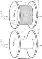
- Figures 1A to 1C show various views of a conventional non-collapsible reel 100.
- Figure 1A shows a reel 100 bearing a cable 102;
- Figures 1B and 1C show the reel 100 without the cable 102.
- the term "cable 102" will encompass cable, conduit, or tubing.
- the reel 100 is shown in a three-dimensional view relative to a three-dimensional coordinate system including a first axis AX1 (e.g., x-axis), a second axis AX2 ( e.g., y-axis), and a third axis AX3 ( e.g ., z-axis), with each axis being perpendicular to the other two axes.
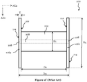
- Figure 1C shows a two-dimensional view of the reel 100 in the AX1-AX2 plane of the AX1, AX2, AX3 coordinate system ( e.g ., Figure 1C is a top-down view of the reel 100 shown in Figure 1B ).
- the cable 102 may be an optical cable (e.g. , including one or more optical fibers within an outer jacket), an electrical cable (e.g. , for high-voltage power distribution), or the like.
- the cable 102 may weigh between 2 kilograms/meter and 100 kilograms/meter ( e.g ., about 30 kilograms/meter).
- the cable 102 is wrapped around a central member 104 of the reel 100.
- the central member 104 e.g., a drum or spool
- the central member 104 is a substantially cylindrical shape and is disposed between opposing end portions 106a, 106b of the reel 100.
- the central member 104 may be secured to the end portions 106a, 106b by screws, bolts, nails, or a weld, as examples, depending on the material of the central member 104 and the end portions 106a, 106b.
- the elements used to secure the end portions 106a, 106b and the central member 104 to each other are not shown in Figures 1A to 1C for the sake of simplicity.
- the end portions 106a, 106b are circular in shape and have an opening 108 that extends through a central region of the end portions 106a, 106b and through a central region of the central member 104 (see, e.g ., Figure 1C ).
- the opening 108 is configured to accommodate a support rod, and the cable 102 is pulled on/from the reel 100 as it rotates about the axis of the support rod.
- a direction of rotation of the reel 100 is illustratively shown as arrow 110 in Figure 1A .
- each of the end portions 106a, 106b includes a first major surface 112 that is inward-facing. Stated differently, the first major surface 112 of the first end portion 106a is directed to the first major surface 112 of the second end portion 106b, with the central member 104 being disposed between and contacting the first major surfaces 112 of the end portions 106a, 106b.
- Each of the end portions 106a, 106b includes a second major surface 114 that is outward-facing. In other words, the second major surface 114 of the first end portion 106a and the second major surface 114 of the second end portion 106b is directed away from the central member 104 and forms outward-facing surfaces of the reel 100.
- the central member 104 of the reel 100 has a first dimension D1 along the first axis AX1 and a second dimension D2 along the second axis AX2.
- the first dimension D1 corresponds to a maximum diametric extent of the central member 104 along the first axis AX1 and is indicative of an outer diameter of the central member 104.
- the second dimension D2 corresponds to a maximum longitudinal extent of the central member 104 along the second axis AX2 and is indicative of a distance separating the first major surfaces 112 of the end portions 106a, 106b.
- the second major surfaces 114 of the end portions 106a, 106b are separated by a third dimension D3 along the second axis AX2.
- a difference between the third dimension D3 and the first dimension D1 is equal to twice a thickness T of each of the end portions 106a, 106b along the second axis AX2.
- a widest lateral extent of respective end portions 106a, 106b along the first axis AX1 is represented by a fourth dimension D4, which corresponds to an outer diameter of each of the end portions 106a, 106b.
- At least one of the dimensions D1, D2, D3, or D4 and/or the material of the reel 100 determine a maximum load (e.g., a maximum weight of the cable 102) that can be safely supported by the reel 100 during its use or transport.
- the end portions 106a, 106b and the central member 104 are made of plywood, timber, plastic, or metal, depending on the weight and the type of cable 102 and whether the reel 100 is designed to be reusable and/or returnable. Additionally, the choice of material for the reel 100 depends on whether the reel 100 and the cable 102 are being stored indoors or outdoors.
- a plastic reel 100 can have a fourth dimension D4 between 400 mm and 1000 mm and can carry loads of up to 850 kilograms; a plywood reel 100 can have a fourth dimension D4 between 125 mm and 1500 mm and can carry loads of up to 2 tons; a timber reel 100 can have a fourth dimension D4 between 250 mm and 4500 mm and can carry loads of up to 60 tons; and a metal reel 100 ( e.g ., iron or steel) can have a fourth dimension D4 between 630 mm and 10000 mm and can carry loads of up to 250 tons.
- power cable industrial uses of the reel 100 require that the reel 100 be robust and hold loads of at least 200 kg, but usually metal or timber reel 100 are chosen as they can be suitable for a wide variety of cables and can stand even long-term outdoor storage.
- a feature of the conventional reel 100 is that once the reel 100 is manufactured having a given size for a given maximum load and from a given material, the first dimension D1 and the second dimension D2 of the reel 100 are fixed and non-adjustable.
- the reel 100 cannot be collapsed when the reel 100 is empty ( e.g ., when the reel 100 is not carrying any cable 102) and its size cannot be varied to support different amounts (e.g ., lengths) or types of cable 102 below its maximum load.
- a dismountable reel has been envisioned (e.g. in German patent application DE 10220265C1 ), where the end portions 106a, 106b are separable from the central member 104 prior to its transportation or storage. Separation of the end portions 106a, 106b from the central member 104 involves a process of loosening the elements (e.g ., screws, bolts, or nails) that secure the end portions 106a, 106b and the central member 104 to each other and subsequently pulling apart the end portions 106a, 106b and the central member 104 to dismantle the reel 100.
- elements e.g ., screws, bolts, or nails
- Figures 2A to 2C show a second example of a proposed solution.
- the example of Figures 2A to 2C (e . g. , proposed in US Patent Application Publication No. 2005/0051664 ) is a fully-collapsible reel where the central member 104 is replaced by a plurality of support units 200 that circumscribe an imaginary cylinder in the three-dimensional AX1, AX2, AX3 coordinate system.
- Figures 2A to 2C show side views of the fully-collapsible reel in the AX1-AX2 plane.
- each support unit 200 includes a pair of interconnected end-to-end leg segments 200a, 200b that are joined to each other by a pivot pin 202.
- Each support unit 200 is also hingedly/pivotably connected (via further pivot pins) to the opposing first major surfaces 112 of the end portions 106a, 106b.
- each support unit 200 is fully extended, thereby forming a substantially flat surface F across each support unit 200, thereby allowing the reel of Figure 2A to support and carry a cable 102.
- each support unit 200 is foldable about its respective pivot pin 202, thereby moving the pivot pins 202 radially and bringing the end portions 106a, 106b in progressively closer proximity to each other.
- the leg segments 200a, 200b are gradually accommodated into recesses formed in the end portions 106a, 106b until the opposing first major surfaces 112 of the end portions 106a, 106b are abutting or physically contacting each other, as shown in Figure 2C .
- the reel, when fully collapsed, is no thicker than twice the thickness T of each of the end portions 106a, 106b, as illustrated in Figure 2C .
- the fully-collapsible reel of Figures 2A to 2C suffers from several disadvantages, including the feature that the reel only has two structurally stable configurations, namely, the fully-extended state of Figure 2A and the fully-collapsed state of Figure 2C .
- the partially-collapsed state of Figure 2C is not structurally stable due, at least in part, to the support units 200 not being in a locked position while folded about its respective pivot pin 202.
- the structure of Figure 2B is not amenable to supporting a cable 102 since each of the leg segments 200a, 200b forms a non-flat surface between the end portions 106a, 106b. Consequently, the reel proposed in Figures 2A to 2C , while fully-collapsible, is still non-adjustable since its size cannot be varied to safely support different lengths or types of cable 02 below its maximum load.
- reels that are adjustable in size so as to support cables 102 of different sizes, lengths or weights during transportation or storage.
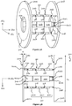
- Figures 3A, 3B , 4A, and 4B illustrate a collapsible and adjustable reel 300, in accordance with an embodiment of the present disclosure.
- Figures 3A, 3B , 4A, and 4B show an empty reel 300; however, it is understood that the reel 300 is configured to support or carry the cable 102 described above in reference to Figure 1A .
- Figures 3A and 3B illustrate the reel 300 in a fully-extended position
- Figures 4A and 4B illustrate the reel 300 in a collapsed (e.g., partially collapsed) and adjusted position relative to Figures 3A and 3B .
- the embodiment reel 300 is adjustable in size and is structurally stable at each of the adjusted sizes.
- the reel 300 includes opposing flanges 302a, 302b, which are circular in shape and that have an opening 304 that extends through a central region of each of the flanges 302a, 302b.
- Figures 5A and 5B show views of inward-facing surfaces of the flanges 302a, 302b, in accordance with an embodiment
- Figures 5C and 5D show views of inward-facing surfaces of the flanges 302a, 302b, in accordance with another embodiment.
- Figures 6A and 6B show cross-sections of a portion of the flanges 302a, 302b.
- each segmented structure 312 includes a plurality of links 312a, 312b, 312c, and Figures 7A to 7D show the structure of each link of a segmented structure 312.
- Each segmented structure 312 can be fully-extended (as in Figures 3A and 3B ), and Figures 8A to 8D show the structure of a fully-extended segmented structure 312.
- Each segmented structure 312 can be pivotably-collapsed in size (as in Figures 4A and 4B ), and Figure 9 shows the structure of a pivotably-collapsed segmented structure 312.
- Figures 5A, 5B , 6A, 6B , 7A to 7D , 8A to 8D , and 9 will be discussed in greater detail below.
- Figures 3A, 3B , 4A, and 4B show the reel 300 in a three-dimensional view relative to the three-dimensional AX1, AX2, AX3 coordinate system.
- Figures 3B and 4B show two-dimensional views of the reel 300 in the AX1-AX2 plane of the AX1, AX2, AX3 coordinate system.
- the reel 300 includes opposing flanges 302a, 302b, which may be coaxial and circular in shape.
- the opening 304 that extends through the central region of the flanges 302a, 302b is configured to accommodate a support rod so that when the reel 300 is loaded with/unloaded of the cable 102, the cable 102 may be wound on/pulled from the reel 300 as it rotates about the axis of the support rod.
- a direction of rotation of the reel 300 is illustratively shown as arrow 306 in Figure 3A .
- the reel 300 and the support rod may be positioned on a stand. Additionally or alternatively, the reel 300 and the support rod may be supported for rotation on a body of a mobile vehicle ( e.g ., a truck).
- the entire reel 300 can be formed from the same material, at least in power cable industrial uses.
- the flanges 302a, 302b may be formed from a metal-containing material (e.g. , iron or steel) or timber depending on the desired size, weight, and durability of the reel 300.
- each of the flanges 302a, 302b includes a respective first major surface 308a, 308b that is inward-facing such that the first major surface 308a of a first flange 302a is directed towards the first major surface 308b of a second flange 302b.
- Each of the flanges 302a, 302b includes a respective second major surface 310a, 310b that is outward-facing and that collectively form outward-facing surfaces of the reel 300.
- a widest diametric extent of each of the flanges 302a, 302b along the first axis AX1 may be represented by dimension D5, which may correspond to an outer diameter of each of the flanges 302a, 302b.
- the dimension D5 may be between 100 mm and 6000 mm ( e.g. , in cases where the reel 300 is configured for industrial use).
- Each of the flanges 302a, 302b may have the thickness T' along the second axis AX2, which may be between 1 mm and 30 mm.
- the flanges 302a, 302b are mechanically coupled to each other by the plurality of segmented structures 312, as illustrated in Figures 3A and 3B .
- a first end 314a of each segmented structure 312 is pivotably coupled to the first flange 302a by a respective first end pivot rod 316a
- second ends 314b of each segmented structure 312 is pivotably coupled to the second flange 302b by a respective second end pivot rod 316b.
- brackets 600a and 600b may extend from the first major surface 308a of the first flange 302a and from the first major surface 308b of the second flange 302b, respectively.
- first end 314a of each segmented structure 312 may be pivotably coupled to a respective bracket 600a of the first flange 302a (by first end pivot rod 316a) and the second ends 314b of each segmented structure 312 may be pivotably coupled to a respective bracket 600b of the second flange 302b (by second end pivot rod 316b), as illustrated in Figures 3A and 3B .
- Each segmented structure 312 includes the plurality of segments 312a, 312b, 312c (which may also be referred to as "links") that are pivotably coupled to each other by intermediate pivot rods 318.
- links there are at least three links 312a, 312b, 312c that form each segmented structure 312.
- the plurality of segmented structures 312 and the pivot rods 316a, 316b, 318 are formed from the same material as the flanges 302a, 302b since, as mentioned above, the entire reel 300 is formed from the same material.
- FIG. 3A A comparison between Figures 3A and 4A and between Figures 3B and 4B shows that in order to adjust or vary the size of the reel 300, the first end 314a of each segmented structure 312 pivots about its respective first end pivot rod 316a, the second ends 314b of each segmented structure 312 pivot about their respective second end pivot rod 316b, and each of the plurality of links 312a, 312b, 312c of each segmented structure 312 pivots about its intermediate pivot rods 318.
- the structure and spatial properties of the brackets 600a of the first flange 302a and the brackets 600b of the second flange 302b are described.
- Figure 5A shows a view of the first major surface 308a of the first flange 302a
- Figure 5B shows a view of the first major surface 308b of the second flange 302b
- the first flange 302a includes a plurality of brackets 600a disposed along a circumference of the opening 304 of the first flange 302a.
- Each bracket 600a may be spaced along the circumference of the opening 304 so that the first ends 314a of the plurality of segmented structures 312 are equally spaced along the circumference of the opening 304.
- Eight brackets 600a (e.g.
- Brackets 600a are shown in the example of Figure 5A ; however, in other embodiments, other quantities of brackets 600a are possible (although it is noted that there are at least six brackets 600a since there are at least three segmented structures 312).
- first separation distance Si which may be between 10 mm and 1000 mm.
- the first end 314a of each of the segmented structures 312 is accommodated within the first separation distance Si, as illustrated in Figure 3B .
- Each bracket 600a may include an opening 504 extending therethrough, with nearest-neighbor brackets 600a having openings 504 (see also Figure 6A ) that are aligned so as to receive respective first end pivot rod 316a.
- the second flange 302b includes a plurality of brackets 600b disposed along a circumference of the opening 304 of the second flange 302b.
- Each bracket 600b may be spaced along the circumference of the opening 304 so that the second ends 314b of the plurality of segmented structures 312 are equally spaced along the circumference of the opening 304.
- the number of brackets 600b of the second flange 302b may be equal to the number of brackets 600a of the first flange 302a.
- Opposing surfaces of nearest-neighbor brackets 600b are separated by a second separation distance S2.
- the second separation distance S2 may be between 10 mm and 1000 mm.
- the second separation distance S2 may be equal to the first separation distance D1, and in such embodiments, the second ends 314b of each of the segmented structures 312 may be accommodated within the second separation distance S2.
- the second separation distance S2 is less than the first separation distance D1, and in such embodiments, nearest-neighbor brackets 600b are accommodated within a space between second ends 314b of a given segmented structure 312.
- Each bracket 600b may include an opening 508 extending therethrough, with nearest-neighbor brackets 600b having openings 508 that are aligned so as to receive respective second end pivot rod 316b.
- FIG. 5A and 5B illustrates the first flange 302a having a pair of brackets 600a that are aligned so as to receive respective first end pivot rod 316a.
- FIG. 5C other embodiments are possible where the respective first end pivot rod 316a is received by a single bracket 601 having the opening 504 therethrough.
- the brackets 601 of Figure 5C are equally spaced along the circumference of the opening 304.
- the first flange 302a includes four brackets 601; however, in other embodiments, other quantities of brackets 601 are possible (although it is noted that there are at least three brackets 601 since there are at least three segmented structures 312).
- FIG. 5D A similar arrangement is seen in the embodiment of Figure 5D , which illustrates that the respective second end pivot rod 316b may be received by a single bracket 603 having the opening 508 therethrough.
- the brackets 603 of Figure 5D are equally spaced along the circumference of the opening 304.
- the second flange 302b includes four brackets 603; however, in other embodiments, other quantities of brackets 603 are possible (although it is noted that there are at least three brackets 603 since there are at least three segmented structures 312).
- the description and figures that follow are directed to the embodiment of Figures 5A and 5B with the brackets 600a, 600b arranged as pairs.
- Figure 6A shows a cross-sectional view of a bracket 600a of the first flange 302a along the line A-A' in Figure 5A
- Figure 6B shows a cross-sectional view of a bracket 600b of the second flange 302b along the line B-B' in Figure 5B
- the bracket 600a extends or protrudes from the first major surface 308a of the first flange 302a and may be formed from the same material as the first flange 302a.
- the bracket 600a may have a height BH1 that may be between 10 mm and 200 mm, while the opening 504 of the bracket 600a may have a diameter of between 1 mm and 30 mm to accommodate the first end pivot rod 316a that pivotably couples the bracket 600a to its respective segmented structure 312. Since the bracket 600a is pivotably coupled to its respective segmented structure 312, the height BH1 of the bracket 600a may depend, at least in part, on a location of an opening within the respective segmented structure 312 that accommodates the first end pivot rod 316a. The location of the opening within the respective segmented structure 312 that accommodates the first end pivot rod 316a is described in greater detail below in reference to Figures 7A to 7D , 8A to 8D , and 9 .
- the bracket 600b extends or protrudes from the first major surface 308b of the second flange 302b and may be formed from the same material as the second flange 302b.
- the bracket 600b may have a height BH2 that may be less than the height BH1 of the bracket 600a, while the opening 508 of the bracket 600b may have a diameter that is equal to the diameter of the opening 504 of the bracket 600a so as to accommodate the second end pivot rod 316b that pivotably couples the bracket 600b to its respective segmented structure 312.
- the height BH2 of the bracket 600b may depend, at least in part, on a location of an opening within the second ends 314b that accommodates the second end pivot rod 316b.
- the location of the opening within the second ends 314b that accommodates the second end pivot rod 316b is described in greater detail below in reference to Figures 7A to 7D , 8A to 8D , and 9 .
- each segmented structure 312 includes a plurality of links 312a, 312b, 312c that are pivotably coupled to each other by intermediate pivot rods 318.
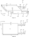
- Figures 7A to 7D show various views of a single link 312a of the segmented structure 312, in accordance with an embodiment. It is noted that the structure of the single link 312a is identical to the structure of the other links 312b, 312c of the segmented structure 312.
- Figure 7A shows a three-dimensional view of the link 312a relative to the AX1, AX2, AX3 coordinate system
- Figures 7B to 7D show various two-dimensional views of the link 312a in different planes of the AX1, AX2, AX3 coordinate system.
- the link 312a includes a planar region 702 having a first major surface 704 (see Figures 7A and 7B ) and a second major surface 706 (see Figures 7A and 7C ) opposite the first major surface 704.
- the juxtaposition of major surfaces 704 and 706 of the planar region 702 of the link 312a is also seen in Figure 7D .
- the planar region 702 may have a first dimension L1 along the first axis AX1 and a second dimension L2 along the second axis AX2.
- the first dimension L1 may be between 1 mm to 30 mm, while the second dimension L2 may be between 5 mm and 2000 mm.
- Figures 7A to 7D also show that the link 312a further includes a first sidewall 708a and a second sidewall 708b at opposite sides of the second major surface 706 of the planar region 702.
- the first sidewall 708a and the second sidewall 708b may be integral with the planar region 702 of the link 312a and serve to pivotably couple the link 312a to an adjacent link or to one of the flanges 302a, 302b.
- the first sidewall 708a includes a first end 710a that is located within the perimeter of the planar region 702; the first sidewall 708a also includes a second end 712a, opposite the first end 710a, that extends outside the perimeter of the planar region 702.
- the second sidewall 708b includes a first end 710b that is located within the perimeter of the planar region 702; the second sidewall 708b also includes a second end 712b, opposite the first end 710b, that extends outside the perimeter of the planar region 702.
- the second ends 712a, 712b of the sidewalls 708a, 708b may be located 10 mm and 200 mm from the closest edge of the planar region 702 (indicated in Figures 7B and 7C as third dimension L3 along the second axis AX2).
- the link 312a additionally includes through-holes 714 that extend through the first sidewall 708a and the second sidewall 708b.
- the first sidewall 708a includes a through-hole 714 proximate the first end 710a of the first sidewall 708a and another through-hole 714 proximate the second end 712a of the first sidewall 708a.
- the second sidewall 708b includes a through-hole 714 proximate the first end 710b of the second sidewall 708b and another through-hole 714 proximate the second end 712b of the second sidewall 708b.
- the through-holes 714 at the first ends 710a, 710b of the sidewalls 708a, 708b are aligned to accommodate an intermediate pivot rod 318 ( e.g. , when first ends 710a, 710b are coupled to an adjacent link) or a first end pivot rod 316a ( e.g. , when first ends 710a, 710b are coupled to a bracket 600a of the first flange 302a).
- the through-holes 714 at the second ends 712a, 712b of the sidewalls 708a, 708b are aligned to accommodate an intermediate pivot rod 318 ( e.g ., when second ends 712a, 712b are coupled to an adjacent link) or a second end pivot rod 316b ( e.g ., when second ends 712a, 712b are coupled to a bracket 600b of the second flange 302b).
- a diameter of the through-holes 714 and the diameters of openings 504, 508 of the brackets 600a, 600b may be at least 10 mm (300 mm at most), while the diameters of the first end pivot rods 316a, second end pivot rods 316b, and intermediate pivot rods 318 are less than the diameter of the through-holes 714 and the diameters of openings 504, 508 of the brackets 600a, 600b.
- each sidewall 708a, 708b includes a central region 716 disposed within the perimeter of the planar region 702, a first leg 718 extending from the central region 716 across a portion of the second major surface 706 of the planar region 702, and a second leg 720 protruding outside the perimeter of the planar region 702. Extremities of the first legs 718 form the first ends 710a, 710b of the sidewalls 708a, 708b, while extremities of the second legs 720 form the second ends 712a, 712b of the sidewalls 708a, 708b.
- the first leg 718 and the second leg 720 of a respective sidewall 708a, 708b are not aligned but are, instead, offset from each other to form a stepped structure 722 at the second major surface 706 of the planar region 702 and within the perimeter thereof.
- the stepped structures 722 function to accommodate second ends 712a, 712b of an adjacent link.
- Figure 7D shows an overhang 722 formed by the portion of the planar region 702 that protrudes over the first ends 710a, 710b.
- the overhang 722 forms the first end 314a of the segmented structure 312. It is further noted that when the link 312a is the link in closest proximity to second flange 302b, the second ends 712a, 712b of the sidewalls 708a, 708b form the second ends 314b of the segmented structure 312.
- a segmented structure of the plurality of segmented structures 312 may be formed by pivotably coupling the plurality of links 312a, 312b, 312c end-to-end.
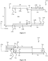
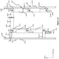
- Figures 8A to 8D show various views of a single segmented structure 312, including links 312a, 312b, 312C, when the reel 300 is in a fully-extended position, while Figure 9 shows a view of the single segmented structure 312 when the reel 300 is in a partially-collapsed and adjusted position.
- Figure 8A shows a three-dimensional view of the segmented structure 312 relative to the AX1, AX2, AX3 coordinate system
- Figures 8B to 8D and 9 show various two-dimensional views of the segmented structure 312 in different planes of the AX1, AX2, AX3 coordinate system.
- a pair of brackets 600a of the first flange 302a are pivotably coupled to the link 312a by the first end pivot rod 316a, with the brackets 600a overlying the sidewalls 708a, 708b of the link 312a.
- the first end pivot rod 316a passes through the through-holes of the first ends 710a, 710b of link 312a and through the openings of the brackets 600a.
- the second ends 712a, 712b of link 312a are pivotably coupled to link 312b by an intermediate pivot rod 318.
- first ends 710a, 710b of link 312b are coupled by intermediate pivot rod 318 to second ends 712a, 712b of link 312a.
- the intermediate pivot rod 318 passes through the through-holes of the first ends 710a, 710b of link 312b and the through-holes of second ends 712a, 712b of link 312a, thereby pivotably securing links 312a and 312b together.
- second ends 712a, 712b of link 312b are pivotably coupled to link 312c by another intermediate pivot rod 318.
- brackets 600b of second flange 302b are pivotably coupled to the link 312c by the second end pivot rod 316b, with the second ends 712a, 712b of link 312c overlying brackets 600b of the second flange 302b.
- the second end pivot rod 316b passes through the through-holes of the second ends 712a, 712b of link 312c and the openings of brackets 600b, thereby pivotably securing link 312c and brackets 600b together.
- the intermediate pivot rods 318 serve as fulcrums around which immediately adjacent links rotate.
- the first and second end pivot rods 316a, 316b serve as fulcrums around which the ends 314a, 314b of the segmented structures 312 rotate.
- the first end 314a of segmented structure 312, formed by the overhang 722 of link 312a rotates ( e.g. , by about 90 degrees) about the first end pivot rod 316a and the second ends 712a, 712b of link 312a rotate ( e.g. , by about 90 degrees) about intermediate pivot rod 318 between links 312a and 312b so as to bring an edge of the overhang 722 of link 312b in contact ( e.g ., physical contact) with the first major surface 308 of first flange 302a.
- planar region 702 of link 312c rotates ( e.g ., by about 90 degrees) about intermediate pivot rod 318, while the second ends 712a, 712b of link 312c rotate ( e.g ., by about 90 degrees) about the second end pivot rod 316b so as to bring the first major surface 704 of planar region 702 of link 312c in contact ( e.g ., physical contact) with the first major surface 308 of second flange 302b.
- a substantially flat surface 900, 902 is formed between first and second flanges 302a, 302b, which allows for the adjusted reel 300 of Figures 4A and 4B to robustly support a cable of varying sizes, lengths or weights during transportation or storage.
- a step S is formed between a surface 900 and surface 902, and the step S may be between 10 mm and 1000 mm, thus causing negligible variation in the flatness of the surface 900, 902 in comparison with a size of the cable 102.
- Structural stability of the adjusted reel 300 is maintained by an outward force F1 being exerted by the overhang 722 of link 312b of each segmented structure 312 onto the first major surface 308a of first flange 302a and by another outward force F2 being exerted by the planar region 702 of link 312c of each segmented structure 312 onto the first major surface 308b of second flange 302b.
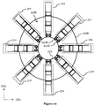
- segmented structures 312 are shown in the reel 300 of Figures 3A, 3B , 4A, and 4B .
- the number of segmented structures 312 that are arranged along a perimeter of the openings 304 may differ for other embodiments (e.g. as shown in Figure 10 ), with an increased number of segmented structures 312 arranged along the perimeter of the openings 304 causing an increase in a maximum weight limit of the reel 300.
- each segmented structure 312 having three links 312a, 312b, 312c.
- more than three links may be possible in other embodiments, with an increased number of links causing an increase in a distance between the first major surfaces 308 of the flanges 302a, 302b.
- Figure 11A shows an embodiment where each segmented structure 312 is fully-extended and includes four links 312a, 312b, 312d.
- Figure 11B shows an adjustment or partial collapse of the segmented structure 312 shown in Figure 11A , where terminal links 312a, 312d rotate about their respective end pivot rods 316a, 316b and intermediate pivot rods 318 to form the segmented structure 312 shown in Figure 11B , which causes a change in the distance between the first major surfaces 308a, 308b of the flanges 302a, 302b compared to Figure 11A .
- each segmented structure 312 may determine the number of possible sizes of the reel 300.
- Figure 12A shows an embodiment where five links 312a to 312e form a single segmented structure 312 in a fully-extended state.
- Such a segmented structure 312 may have two other configurations when the reel 300 is partially collapsed or adjusted.
- Figure 12B three links 312b, 312c, 312d provide the substantially flat surface 900, 902 between first and second flanges 302a, 302b, while in Figure 12C , link 312c provides the substantially flat surface 900, 902 between first and second flanges 302a, 302b.
- each of the configurations shown in Figures 12A to 12C has a different distance between major surfaces 308 of first and second flanges 302a, 302b and each configuration is structurally stable (e.g. for at least the reasons discussed above in reference to Figure 9 ). Consequently, in the embodiment of Figures 12A to 12C , the reel 300 can have three different sizes, each of which is structurally stable and configured to support cables 102 of varying sizes, lengths or weights during transportation or storage.
- various embodiments of the reel 300 shown in Figures 3A, 3B , 4A, 4B , 5A, 5B , 6A, 6B , 7A to 7D , 8A to 8D , 9 , 10 , 11A , 11B , and 12A to 12C require less space to store and transport when empty or loaded below its maximum capacity/load. Additionally, in comparison to the above-described dismountable reel, the reel 300 can be easily collapsed without the need to dismantle the reel.
- the reel 300 has a modular structure, which allows it to be adjusted to different reel sizes in order to support cables 102 of varying sizes, lengths or weights during transportation or storage, while maintaining structural stability at each of the different reel sizes.
- Figure 13A shows a given area 1300 storing a particular number of conventional reels 100, with the same area 1301 in Figure 13B being able to store a greater number of reels 300 by virtue of their collapsible and adjustable nature.
- Figure 14A shows a truck 1400 carrying a particular number of conventional reels 100, with the same truck 1400 in Figure 14B being able to store a greater number of reels 300 by virtue of their collapsible and adjustable nature.
- a collapsible and adjustable reel is proposed, where the collapsible and adjustable reel includes two opposed flanges 302a, 302b and a plurality (e.g. at least three) segmented structures 312, each of which includes at least three links 312a, 312b, 312c joined end-to-end by respective pivot pins 318 and configured to be folded (e.g., in a radially inward direction) independently one another.
- the proposed collapsible and adjustable reel can be partially collapsed and used for transporting cables when the reel is empty or loaded below its maximum capacity/load.
Landscapes
- Storage Of Web-Like Or Filamentary Materials (AREA)
Abstract
Description
- The present disclosure relates generally to a reel for power cables, conduits, or tubings and, in particular embodiments, to a collapsible and adjustable reel.
- Reels are used for storing and dispensing a wide variety of cables and the like. Power cables, especially for medium voltage (MV) or high voltage (HV) transport, may comprise from one to three insulated metal electric conductors collectively protected by one or more layers. Depending on the amount of current carried and, accordingly, on the conductor cross-section, such cables can weigh from 2 up to 100 Kg/m. Length from 100 m to 3000 m or more of such cables are to be wound on reel for transport. For this reason, reels for cable storage/transport should be robust and are bulky, accordingly.
- Reels for storing/carrying power cables typically include a hollow tubular core extending between spaced-apart end portions that are circular in shape. In general, power cables wound around the core are held in place by the end portions. Reels bearing cables for industrial transport and storage vary greatly in size and such variance can increase the costs associated with transporting and storing wires and cables on reels.
- In an aspect, the present disclosure relates to a reel, comprising:
- a first flange comprising at least one first bracket extending from a first major surface of the first flange;
- a second flange comprising at least one second bracket extending from a first major surface of the second flange, wherein the first major surface of the second flange is directed toward the first major surface of the first flange; and
- a plurality of segmented structures each comprising a plurality of links pivotably coupled to the at least one first bracket by a first end pivot rod and to the at least one second bracket by a second end pivot rod, the plurality of links being configured to have a first stable arrangement and a second stable arrangement different from the first stable arrangement, wherein:
- in the first stable arrangement, the first flange and the second flange are separated by a first distance with the reel being configured to support a first maximum load of cable; and
- in the second stable arrangement, the first flange and the second flange are separated by a second distance less than the first distance with the reel being configured to support a second maximum load of cable less than the first maximum load of cable.
- In an embodiment, the first flange comprises a pair of first brackets extending from a first major surface of the first flange, and/or the second flange comprises a pair of second brackets.
- In an embodiment, the plurality of segmented structures of the reel of the disclosure comprises at least three segmented structures.
- In an embodiment, the plurality of links comprises at least three links.
- In an embodiment, in the first stable arrangement, the plurality of links is fully-extended end-to-end, and an angle subtended between adjacent links of the plurality of links is about 0 degrees.
- In an embodiment, in the second stable arrangement, adjacent links of the plurality of links are rotated about an intermediate pivot rod pivotably joining the adjacent links, and an angle subtended between the adjacent links is about 90 degrees.
- In an embodiment, each link of the plurality of links of the present reel comprises:
- a planar region; and
- parallel sidewalls extending from opposing edges of the planar region, wherein the parallel sidewalls comprise first legs disposed within a perimeter of the planar region, and second legs disposed outside the perimeter of the planar region.
- Accordingly, in an embodiment the plurality of links comprises a first terminal link, an adjacent link, and a second terminal link, wherein:
- the first legs of the first terminal link are pivotably coupled to the at least one first bracket by the first end pivot rod extending through aligned openings in the first legs of the first terminal link and the at least one first bracket;
- the second legs of the first terminal link are pivotably coupled to the first legs of the adjacent link by a first intermediate pivot rod extending through aligned openings in the second legs of the first terminal link and the first legs of the adjacent link;
- the second legs of the adjacent link are pivotably coupled to the first legs of the second terminal link by a second intermediate pivot rod extending through aligned openings in the second legs of the adjacent link and the first legs of the second terminal link; and
- the second legs of the second terminal link are pivotably coupled to the at least one second bracket by the second end pivot rod extending through aligned openings in the second legs of the second terminal link and the at least one second bracket.
- In an embodiment, the planar region of the first terminal link is accommodated within a space between the at least one first bracket, and the at least one second bracket is accommodated within a space between the second legs of the second terminal link.
- In an embodiment, in the second stable arrangement:
- the planar region of the first terminal link is directed toward and spaced apart from the first major surface of the first flange;
- an edge of the planar region of the adjacent link is in physical contact with the first major surface of the first flange; and
- the planar region of the second terminal link is directed toward and in physical contact with the first major surface of the second flange.
- In an embodiment, the plurality of links comprises immediately adjacent links, and the second legs of a first one of the immediately adjacent links are accommodated within a space between the first legs of a second one of the immediately adjacent links.
- In another, aspect, the present disclosure relates to a reel, comprising:
- a pair of opposed coaxial flanges; and
- a plurality of support structures disposed between the pair of opposed coaxial flanges and pivotably coupled to each of the pair of opposed coaxial flanges, plurality of support structures being configured to support a cable and to vary a distance between the pair of opposed coaxial flanges, wherein the plurality of support structures are arranged along a perimeter of an opening extending through each of the pair of opposed coaxial flanges, and wherein each of the plurality of support structures comprises at least three links joined end-to-end and pivotably coupled to each other, each link comprising:
- a planar region; and
- parallel legs extending from opposing edges of the planar region toward an axis of rotation of the reel, wherein the parallel legs comprise first ends disposed within a perimeter of the planar region, and second ends disposed outside the perimeter of the planar region.
- In an embodiment, the at least three links comprise a first linked arrangement wherein the planar regions of the at least three links collectively lie in a two-dimensional plane, and wherein the planar region of each of the at least three links overhangs the second ends of the parallel legs of an immediately adjacent link.
- In an embodiment, the at least three links comprise a second linked arrangement wherein the planar regions of the at least three links lie in different two-dimensional planes.
- In an embodiment, the first linked arrangement and the second linked arrangement are structurally stable arrangements of the reel.
- For a more complete understanding of the present disclosure, and the advantages thereof, reference is now made to the following descriptions taken in conjunction with the accompanying drawings, in which:
-
Figures 1A to 1C illustrate a conventional non-collapsible reel; -
Figures 2A to 2C illustrate a conventional fully-collapsible reel; -
Figures 3A, 3B ,4A, and 4B illustrate a collapsible and adjustable reel, in accordance with an embodiment of the present disclosure; -
Figures 5A to 5D show a first flange and a second flange of the collapsible and adjustable reel ofFigures 3A, 3B ,4A, and 4B ; -
Figures 6A and 6B show brackets a first flange and a second flange of the collapsible and adjustable reel ofFigures 3A, 3B ,4A, and 4B ; -
Figures 7A to 7D show various views of a single link of a segmented structure of the collapsible and adjustable reel ofFigures 3A, 3B ,4A, and 4B ; -
Figures 8A to 8D ,10 ,11A , and12A show a fully-extended segmented structure including a plurality of links; -
Figures 9 ,11B ,12B , and12C show a partially-collapsed segmented structure including a plurality of links; -
Figures 13A and13B show an area storing conventional non-collapsible reels and an area storing collapsible and adjustable reels, respectively; -
Figures 14A and 14B show a truck transporting conventional non-collapsible reels and a truck transporting collapsible and adjustable reels, respectively. - Corresponding numerals and symbols in the different figures generally refer to corresponding parts unless otherwise indicated. The figures are drawn to clearly illustrate the relevant aspects of the embodiments and are not necessarily drawn to scale.
- The making and using of the present embodiments are discussed in detail below. It should be appreciated, however, that the present disclosure provides many applicable inventive concepts that can be embodied in a wide variety of specific contexts. The specific embodiments discussed are merely illustrative of specific ways to make and use the described object, and do not limit the scope thereof.
- For the purpose of the present description and of the appended claims, except where otherwise indicated, all numbers expressing amounts, quantities, percentages, and so forth, are to be understood as being modified in all instances by the term "about". Also, all ranges include any combination of the maximum and minimum points disclosed and include any intermediate ranges therein, which may or may not be specifically enumerated herein.
- The present disclosure, in at least one of the aforementioned aspects, can be implemented according to one or more of the following embodiments, optionally combined together.
- For the purpose of the present description and of the appended claims, the words "a" or "an" should be read to include one or at least one and the singular also includes the plural unless it is obvious that it is meant otherwise. This is done merely for convenience and to give a general sense of the disclosure.
-
Figures 1A to 1C show various views of a conventionalnon-collapsible reel 100.Figure 1A shows areel 100 bearing acable 102;Figures 1B and1C show thereel 100 without thecable 102. For the sake of brevity the term "cable 102" will encompass cable, conduit, or tubing. InFigures 1A and 1B , thereel 100 is shown in a three-dimensional view relative to a three-dimensional coordinate system including a first axis AX1 (e.g., x-axis), a second axis AX2 (e.g., y-axis), and a third axis AX3 (e.g., z-axis), with each axis being perpendicular to the other two axes.Figure 1C shows a two-dimensional view of thereel 100 in the AX1-AX2 plane of the AX1, AX2, AX3 coordinate system (e.g.,Figure 1C is a top-down view of thereel 100 shown inFigure 1B ). - The
cable 102 may be an optical cable (e.g., including one or more optical fibers within an outer jacket), an electrical cable (e.g., for high-voltage power distribution), or the like. Thecable 102 may weigh between 2 kilograms/meter and 100 kilograms/meter (e.g., about 30 kilograms/meter). Thecable 102 is wrapped around acentral member 104 of thereel 100. The central member 104 (e.g., a drum or spool) is a substantially cylindrical shape and is disposed between opposingend portions reel 100. Thecentral member 104 may be secured to theend portions central member 104 and theend portions end portions central member 104 to each other are not shown inFigures 1A to 1C for the sake of simplicity. - The
end portions opening 108 that extends through a central region of theend portions Figure 1C ). Theopening 108 is configured to accommodate a support rod, and thecable 102 is pulled on/from thereel 100 as it rotates about the axis of the support rod. A direction of rotation of thereel 100 is illustratively shown asarrow 110 inFigure 1A . - Referring to
Figure 1C , each of theend portions major surface 112 that is inward-facing. Stated differently, the firstmajor surface 112 of thefirst end portion 106a is directed to the firstmajor surface 112 of thesecond end portion 106b, with thecentral member 104 being disposed between and contacting the firstmajor surfaces 112 of theend portions end portions major surface 114 that is outward-facing. In other words, the secondmajor surface 114 of thefirst end portion 106a and the secondmajor surface 114 of thesecond end portion 106b is directed away from thecentral member 104 and forms outward-facing surfaces of thereel 100. - As shown in
Figure 1C , thecentral member 104 of thereel 100 has a first dimension D1 along the first axis AX1 and a second dimension D2 along the second axis AX2. The first dimension D1 corresponds to a maximum diametric extent of thecentral member 104 along the first axis AX1 and is indicative of an outer diameter of thecentral member 104. The second dimension D2 corresponds to a maximum longitudinal extent of thecentral member 104 along the second axis AX2 and is indicative of a distance separating the firstmajor surfaces 112 of theend portions major surfaces 114 of theend portions end portions respective end portions end portions - At least one of the dimensions D1, D2, D3, or D4 and/or the material of the
reel 100 determine a maximum load (e.g., a maximum weight of the cable 102) that can be safely supported by thereel 100 during its use or transport. Theend portions central member 104 are made of plywood, timber, plastic, or metal, depending on the weight and the type ofcable 102 and whether thereel 100 is designed to be reusable and/or returnable. Additionally, the choice of material for thereel 100 depends on whether thereel 100 and thecable 102 are being stored indoors or outdoors. As examples, aplastic reel 100 can have a fourth dimension D4 between 400 mm and 1000 mm and can carry loads of up to 850 kilograms; aplywood reel 100 can have a fourth dimension D4 between 125 mm and 1500 mm and can carry loads of up to 2 tons; atimber reel 100 can have a fourth dimension D4 between 250 mm and 4500 mm and can carry loads of up to 60 tons; and a metal reel 100 (e.g., iron or steel) can have a fourth dimension D4 between 630 mm and 10000 mm and can carry loads of up to 250 tons. In general, power cable industrial uses of thereel 100 require that thereel 100 be robust and hold loads of at least 200 kg, but usually metal ortimber reel 100 are chosen as they can be suitable for a wide variety of cables and can stand even long-term outdoor storage. - Although the
reel 100 comes in a variety of sizes and materials, a feature of theconventional reel 100 is that once thereel 100 is manufactured having a given size for a given maximum load and from a given material, the first dimension D1 and the second dimension D2 of thereel 100 are fixed and non-adjustable. Thereel 100 cannot be collapsed when thereel 100 is empty (e.g., when thereel 100 is not carrying any cable 102) and its size cannot be varied to support different amounts (e.g., lengths) or types ofcable 102 below its maximum load. As a result of the non-adjustable and non-collapsible nature ofconventional reels 100, large costs are incurred by the storage and/or transportation ofempty reels 100 or under-loaded reels 100 (e.g., reels loaded below its maximum load), with excess inventory ofsuch reels 100 generally being stored at third-party facilities. - To address the issue of high costs associated with the storage and/or transportation of empty or under-loaded
reels 100, several solutions have been proposed. As a first example, a dismountable reel has been envisioned (e.g. in German patent applicationDE 10220265C1 ), where theend portions central member 104 prior to its transportation or storage. Separation of theend portions central member 104 involves a process of loosening the elements (e.g., screws, bolts, or nails) that secure theend portions central member 104 to each other and subsequently pulling apart theend portions central member 104 to dismantle thereel 100. However, such a solution is time-consuming and poses a safety hazard to human operators, especially in industrial uses where the size and weight of thereel 100 is sufficient to injure or maim a human being. -
Figures 2A to 2C show a second example of a proposed solution. The example ofFigures 2A to 2C (e.g., proposed inUS Patent Application Publication No. 2005/0051664 ) is a fully-collapsible reel where thecentral member 104 is replaced by a plurality ofsupport units 200 that circumscribe an imaginary cylinder in the three-dimensional AX1, AX2, AX3 coordinate system.Figures 2A to 2C show side views of the fully-collapsible reel in the AX1-AX2 plane. As shown inFigures 2A and 2B , eachsupport unit 200 includes a pair of interconnected end-to-end leg segments pivot pin 202. Eachsupport unit 200 is also hingedly/pivotably connected (via further pivot pins) to the opposing firstmajor surfaces 112 of theend portions Figure 2A , eachsupport unit 200 is fully extended, thereby forming a substantially flat surface F across eachsupport unit 200, thereby allowing the reel ofFigure 2A to support and carry acable 102. - In order to fully collapse the reel of
Figure 2A , eachsupport unit 200 is foldable about itsrespective pivot pin 202, thereby moving the pivot pins 202 radially and bringing theend portions leg segments end portions major surfaces 112 of theend portions Figure 2C . The reel, when fully collapsed, is no thicker than twice the thickness T of each of theend portions Figure 2C . - The fully-collapsible reel of
Figures 2A to 2C suffers from several disadvantages, including the feature that the reel only has two structurally stable configurations, namely, the fully-extended state ofFigure 2A and the fully-collapsed state ofFigure 2C . The partially-collapsed state ofFigure 2C is not structurally stable due, at least in part, to thesupport units 200 not being in a locked position while folded about itsrespective pivot pin 202. Furthermore, even if thesupport units 200 are locked in position while folded about itsrespective pivot pin 202, the structure ofFigure 2B is not amenable to supporting acable 102 since each of theleg segments end portions Figures 2A to 2C , while fully-collapsible, is still non-adjustable since its size cannot be varied to safely support different lengths or types of cable 02 below its maximum load. - In view of the above, there is a need for reels that are adjustable in size so as to support
cables 102 of different sizes, lengths or weights during transportation or storage. -
Figures 3A, 3B ,4A, and 4B illustrate a collapsible andadjustable reel 300, in accordance with an embodiment of the present disclosure.Figures 3A, 3B ,4A, and 4B show anempty reel 300; however, it is understood that thereel 300 is configured to support or carry thecable 102 described above in reference toFigure 1A .Figures 3A and 3B illustrate thereel 300 in a fully-extended position, whileFigures 4A and 4B illustrate thereel 300 in a collapsed (e.g., partially collapsed) and adjusted position relative toFigures 3A and 3B . In contrast to the conventional structures ofFigures 1A to 1C and2A to 2C , theembodiment reel 300 is adjustable in size and is structurally stable at each of the adjusted sizes. As shown inFigures 3A and 3B , thereel 300 includes opposingflanges opening 304 that extends through a central region of each of theflanges Figures 5A and 5B show views of inward-facing surfaces of theflanges Figures 5C and 5D show views of inward-facing surfaces of theflanges Figures 6A and 6B show cross-sections of a portion of theflanges Figures 3A, 3B ,4A, and 4B , theflanges segmented structures 312 arranged along a perimeter of theopening 304. Eachsegmented structure 312 includes a plurality oflinks Figures 7A to 7D show the structure of each link of asegmented structure 312. Eachsegmented structure 312 can be fully-extended (as inFigures 3A and 3B ), andFigures 8A to 8D show the structure of a fully-extendedsegmented structure 312. Eachsegmented structure 312 can be pivotably-collapsed in size (as inFigures 4A and 4B ), andFigure 9 shows the structure of a pivotably-collapsedsegmented structure 312. Each ofFigures 5A, 5B ,6A, 6B ,7A to 7D ,8A to 8D , and9 will be discussed in greater detail below. - Turning first to
Figures 3A, 3B ,4A, and 4B , it is noted thatFigures 3A and4A show thereel 300 in a three-dimensional view relative to the three-dimensional AX1, AX2, AX3 coordinate system.Figures 3B and4B show two-dimensional views of thereel 300 in the AX1-AX2 plane of the AX1, AX2, AX3 coordinate system. As shown inFigures 3A and 3B , thereel 300 includes opposingflanges opening 304 that extends through the central region of theflanges reel 300 is loaded with/unloaded of thecable 102, thecable 102 may be wound on/pulled from thereel 300 as it rotates about the axis of the support rod. A direction of rotation of thereel 300 is illustratively shown asarrow 306 inFigure 3A . To support thereel 300 as it rotates, thereel 300 and the support rod may be positioned on a stand. Additionally or alternatively, thereel 300 and the support rod may be supported for rotation on a body of a mobile vehicle (e.g., a truck). Theentire reel 300 can be formed from the same material, at least in power cable industrial uses. Theflanges reel 300. - As shown in
Figure 3B , each of theflanges major surface major surface 308a of afirst flange 302a is directed towards the firstmajor surface 308b of asecond flange 302b. Each of theflanges major surface reel 300. A widest diametric extent of each of theflanges flanges reel 300 is configured for industrial use). Each of theflanges - The
flanges segmented structures 312, as illustrated inFigures 3A and 3B . In some embodiments, there are at least threesegmented structures 312 arranged along (e.g. equally spaced along) the circumference of theopening 304. Afirst end 314a of eachsegmented structure 312 is pivotably coupled to thefirst flange 302a by a respective firstend pivot rod 316a, while second ends 314b of eachsegmented structure 312 is pivotably coupled to thesecond flange 302b by a respective secondend pivot rod 316b. In order to effect the pivotable coupling between theflanges segmented structure 312,brackets major surface 308a of thefirst flange 302a and from the firstmajor surface 308b of thesecond flange 302b, respectively. In this way, thefirst end 314a of eachsegmented structure 312 may be pivotably coupled to arespective bracket 600a of thefirst flange 302a (by firstend pivot rod 316a) and the second ends 314b of eachsegmented structure 312 may be pivotably coupled to arespective bracket 600b of thesecond flange 302b (by secondend pivot rod 316b), as illustrated inFigures 3A and 3B . - Each
segmented structure 312 includes the plurality ofsegments intermediate pivot rods 318. In some embodiments, there are at least threelinks segmented structure 312. The plurality ofsegmented structures 312 and thepivot rods flanges entire reel 300 is formed from the same material. A comparison betweenFigures 3A and4A and betweenFigures 3B and4B shows that in order to adjust or vary the size of thereel 300, thefirst end 314a of eachsegmented structure 312 pivots about its respective firstend pivot rod 316a, the second ends 314b of eachsegmented structure 312 pivot about their respective secondend pivot rod 316b, and each of the plurality oflinks segmented structure 312 pivots about itsintermediate pivot rods 318. In the description that follows, the structure and spatial properties of thebrackets 600a of thefirst flange 302a and thebrackets 600b of thesecond flange 302b are described. -
Figure 5A shows a view of the firstmajor surface 308a of thefirst flange 302a, whileFigure 5B shows a view of the firstmajor surface 308b of thesecond flange 302b. As shown inFigure 5A , thefirst flange 302a includes a plurality ofbrackets 600a disposed along a circumference of theopening 304 of thefirst flange 302a. Eachbracket 600a may be spaced along the circumference of theopening 304 so that the first ends 314a of the plurality ofsegmented structures 312 are equally spaced along the circumference of theopening 304. Eightbrackets 600a (e.g. arranged as pairs) are shown in the example ofFigure 5A ; however, in other embodiments, other quantities ofbrackets 600a are possible (although it is noted that there are at least sixbrackets 600a since there are at least three segmented structures 312). As illustrated inFigure 5A , opposing surfaces of nearest-neighbor brackets 600a are separated by a first separation distance Si, which may be between 10 mm and 1000 mm. Thefirst end 314a of each of thesegmented structures 312 is accommodated within the first separation distance Si, as illustrated inFigure 3B . Eachbracket 600a may include anopening 504 extending therethrough, with nearest-neighbor brackets 600a having openings 504 (see alsoFigure 6A ) that are aligned so as to receive respective firstend pivot rod 316a. - Referring to
Figure 5B , thesecond flange 302b includes a plurality ofbrackets 600b disposed along a circumference of theopening 304 of thesecond flange 302b. Eachbracket 600b may be spaced along the circumference of theopening 304 so that the second ends 314b of the plurality ofsegmented structures 312 are equally spaced along the circumference of theopening 304. The number ofbrackets 600b of thesecond flange 302b may be equal to the number ofbrackets 600a of thefirst flange 302a. Opposing surfaces of nearest-neighbor brackets 600b are separated by a second separation distance S2. The second separation distance S2 may be between 10 mm and 1000 mm. In some embodiments, the second separation distance S2 may be equal to the first separation distance D1, and in such embodiments, the second ends 314b of each of thesegmented structures 312 may be accommodated within the second separation distance S2. However, in other embodiments, such as in the examples ofFigures 3A, 3B ,4A, 4B ,5A, and 5B , the second separation distance S2 is less than the first separation distance D1, and in such embodiments, nearest-neighbor brackets 600b are accommodated within a space between second ends 314b of a givensegmented structure 312. Eachbracket 600b may include anopening 508 extending therethrough, with nearest-neighbor brackets 600b having openings 508 that are aligned so as to receive respective secondend pivot rod 316b. - The embodiment of
Figures 5A and 5B illustrates thefirst flange 302a having a pair ofbrackets 600a that are aligned so as to receive respective firstend pivot rod 316a. However, as illustrated inFigure 5C , other embodiments are possible where the respective firstend pivot rod 316a is received by asingle bracket 601 having the opening 504 therethrough. As inFigure 5A , thebrackets 601 ofFigure 5C are equally spaced along the circumference of theopening 304. In the example ofFigure 5C , thefirst flange 302a includes fourbrackets 601; however, in other embodiments, other quantities ofbrackets 601 are possible (although it is noted that there are at least threebrackets 601 since there are at least three segmented structures 312). A similar arrangement is seen in the embodiment ofFigure 5D , which illustrates that the respective secondend pivot rod 316b may be received by asingle bracket 603 having the opening 508 therethrough. Thebrackets 603 ofFigure 5D are equally spaced along the circumference of theopening 304. In the example ofFigure 5D , thesecond flange 302b includes fourbrackets 603; however, in other embodiments, other quantities ofbrackets 603 are possible (although it is noted that there are at least threebrackets 603 since there are at least three segmented structures 312). At this point, it is noted that the description and figures that follow are directed to the embodiment ofFigures 5A and 5B with thebrackets -
Figure 6A shows a cross-sectional view of abracket 600a of thefirst flange 302a along the line A-A' inFigure 5A ;Figure 6B shows a cross-sectional view of abracket 600b of thesecond flange 302b along the line B-B' inFigure 5B . Referring first toFigure 6A , thebracket 600a extends or protrudes from the firstmajor surface 308a of thefirst flange 302a and may be formed from the same material as thefirst flange 302a. Thebracket 600a may have a height BH1 that may be between 10 mm and 200 mm, while theopening 504 of thebracket 600a may have a diameter of between 1 mm and 30 mm to accommodate the firstend pivot rod 316a that pivotably couples thebracket 600a to its respectivesegmented structure 312. Since thebracket 600a is pivotably coupled to its respectivesegmented structure 312, the height BH1 of thebracket 600a may depend, at least in part, on a location of an opening within the respectivesegmented structure 312 that accommodates the firstend pivot rod 316a. The location of the opening within the respectivesegmented structure 312 that accommodates the firstend pivot rod 316a is described in greater detail below in reference toFigures 7A to 7D ,8A to 8D , and9 . - Referring now to
Figure 6B , thebracket 600b extends or protrudes from the firstmajor surface 308b of thesecond flange 302b and may be formed from the same material as thesecond flange 302b. Thebracket 600b may have a height BH2 that may be less than the height BH1 of thebracket 600a, while theopening 508 of thebracket 600b may have a diameter that is equal to the diameter of theopening 504 of thebracket 600a so as to accommodate the secondend pivot rod 316b that pivotably couples thebracket 600b to its respectivesegmented structure 312. Since thebracket 600b is pivotably coupled to its respectivesegmented structure 312, the height BH2 of thebracket 600b may depend, at least in part, on a location of an opening within the second ends 314b that accommodates the secondend pivot rod 316b. The location of the opening within the second ends 314b that accommodates the secondend pivot rod 316b is described in greater detail below in reference toFigures 7A to 7D ,8A to 8D , and9 . - Moving now to the description of each
segmented structure 312, as described above, eachsegmented structure 312 includes a plurality oflinks intermediate pivot rods 318. -
Figures 7A to 7D show various views of asingle link 312a of thesegmented structure 312, in accordance with an embodiment. It is noted that the structure of thesingle link 312a is identical to the structure of theother links segmented structure 312.Figure 7A shows a three-dimensional view of thelink 312a relative to the AX1, AX2, AX3 coordinate system, whileFigures 7B to 7D show various two-dimensional views of thelink 312a in different planes of the AX1, AX2, AX3 coordinate system. - The
link 312a includes aplanar region 702 having a first major surface 704 (seeFigures 7A and 7B ) and a second major surface 706 (seeFigures 7A and7C ) opposite the firstmajor surface 704. The juxtaposition ofmajor surfaces planar region 702 of thelink 312a is also seen inFigure 7D . Theplanar region 702 may have a first dimension L1 along the first axis AX1 and a second dimension L2 along the second axis AX2. The first dimension L1 may be between 1 mm to 30 mm, while the second dimension L2 may be between 5 mm and 2000 mm. -
Figures 7A to 7D also show that thelink 312a further includes afirst sidewall 708a and asecond sidewall 708b at opposite sides of the secondmajor surface 706 of theplanar region 702. Thefirst sidewall 708a and thesecond sidewall 708b may be integral with theplanar region 702 of thelink 312a and serve to pivotably couple thelink 312a to an adjacent link or to one of theflanges Figures 7A and7C , thefirst sidewall 708a includes afirst end 710a that is located within the perimeter of theplanar region 702; thefirst sidewall 708a also includes asecond end 712a, opposite thefirst end 710a, that extends outside the perimeter of theplanar region 702. Similarly, as shown inFigure 7C , thesecond sidewall 708b includes afirst end 710b that is located within the perimeter of theplanar region 702; thesecond sidewall 708b also includes asecond end 712b, opposite thefirst end 710b, that extends outside the perimeter of theplanar region 702. The second ends 712a, 712b of the sidewalls 708a, 708b may be located 10 mm and 200 mm from the closest edge of the planar region 702 (indicated inFigures 7B and7C as third dimension L3 along the second axis AX2). - The
link 312a additionally includes through-holes 714 that extend through thefirst sidewall 708a and thesecond sidewall 708b. As an example, thefirst sidewall 708a includes a through-hole 714 proximate thefirst end 710a of thefirst sidewall 708a and another through-hole 714 proximate thesecond end 712a of thefirst sidewall 708a. In a similar way, thesecond sidewall 708b includes a through-hole 714 proximate thefirst end 710b of thesecond sidewall 708b and another through-hole 714 proximate thesecond end 712b of thesecond sidewall 708b. The through-holes 714 at the first ends 710a, 710b of the sidewalls 708a, 708b are aligned to accommodate an intermediate pivot rod 318 (e.g., when first ends 710a, 710b are coupled to an adjacent link) or a firstend pivot rod 316a (e.g., when first ends 710a, 710b are coupled to abracket 600a of thefirst flange 302a). In like manner, the through-holes 714 at the second ends 712a, 712b of the sidewalls 708a, 708b are aligned to accommodate an intermediate pivot rod 318 (e.g., when second ends 712a, 712b are coupled to an adjacent link) or a secondend pivot rod 316b (e.g., when second ends 712a, 712b are coupled to abracket 600b of thesecond flange 302b). Consequently, a diameter of the through-holes 714 and the diameters ofopenings brackets end pivot rods 316a, secondend pivot rods 316b, andintermediate pivot rods 318 are less than the diameter of the through-holes 714 and the diameters ofopenings brackets - As shown in
Figure 7C , eachsidewall central region 716 disposed within the perimeter of theplanar region 702, afirst leg 718 extending from thecentral region 716 across a portion of the secondmajor surface 706 of theplanar region 702, and asecond leg 720 protruding outside the perimeter of theplanar region 702. Extremities of thefirst legs 718 form the first ends 710a, 710b of the sidewalls 708a, 708b, while extremities of thesecond legs 720 form the second ends 712a, 712b of the sidewalls 708a, 708b. As illustrated inFigure 7C , thefirst leg 718 and thesecond leg 720 of arespective sidewall structure 722 at the secondmajor surface 706 of theplanar region 702 and within the perimeter thereof. As described below in reference toFigures 8A to 8D and9 , the steppedstructures 722 function to accommodatesecond ends Figure 7D shows anoverhang 722 formed by the portion of theplanar region 702 that protrudes over the first ends 710a, 710b. It is noted that when thelink 312a is the link in closest proximity tofirst flange 302a, theoverhang 722 forms thefirst end 314a of thesegmented structure 312. It is further noted that when thelink 312a is the link in closest proximity tosecond flange 302b, the second ends 712a, 712b of the sidewalls 708a, 708b form the second ends 314b of thesegmented structure 312. - As described above, a segmented structure of the plurality of
segmented structures 312 may be formed by pivotably coupling the plurality oflinks Figures 8A to 8D show various views of a singlesegmented structure 312, includinglinks reel 300 is in a fully-extended position, whileFigure 9 shows a view of the singlesegmented structure 312 when thereel 300 is in a partially-collapsed and adjusted position.Figure 8A shows a three-dimensional view of thesegmented structure 312 relative to the AX1, AX2, AX3 coordinate system, whileFigures 8B to 8D and9 show various two-dimensional views of thesegmented structure 312 in different planes of the AX1, AX2, AX3 coordinate system. - As illustrated in
Figures 8A to 8D , a pair ofbrackets 600a of thefirst flange 302a are pivotably coupled to thelink 312a by the firstend pivot rod 316a, with thebrackets 600a overlying the sidewalls 708a, 708b of thelink 312a. The firstend pivot rod 316a passes through the through-holes of the first ends 710a, 710b oflink 312a and through the openings of thebrackets 600a. - The second ends 712a, 712b of
link 312a are pivotably coupled to link 312b by anintermediate pivot rod 318. In particular, first ends 710a, 710b oflink 312b are coupled byintermediate pivot rod 318 tosecond ends link 312a. Theintermediate pivot rod 318 passes through the through-holes of the first ends 710a, 710b oflink 312b and the through-holes ofsecond ends link 312a, thereby pivotably securinglinks link 312b are pivotably coupled to link 312c by anotherintermediate pivot rod 318. Furthermore, a pair ofbrackets 600b ofsecond flange 302b are pivotably coupled to thelink 312c by the secondend pivot rod 316b, with the second ends 712a, 712b oflink 312c overlying brackets 600b of thesecond flange 302b. The secondend pivot rod 316b passes through the through-holes of the second ends 712a, 712b oflink 312c and the openings ofbrackets 600b, thereby pivotably securinglink 312c andbrackets 600b together. - In adjusting the
reel 300, theintermediate pivot rods 318 serve as fulcrums around which immediately adjacent links rotate. Similarly, the first and secondend pivot rods ends segmented structures 312 rotate. These features are shown inFigure 9 forlinks - As illustrated in
Figure 9 , thefirst end 314a ofsegmented structure 312, formed by theoverhang 722 oflink 312a, rotates (e.g., by about 90 degrees) about the firstend pivot rod 316a and the second ends 712a, 712b oflink 312a rotate (e.g., by about 90 degrees) aboutintermediate pivot rod 318 betweenlinks overhang 722 oflink 312b in contact (e.g., physical contact) with the firstmajor surface 308 offirst flange 302a. In like manner, theplanar region 702 oflink 312c rotates (e.g., by about 90 degrees) aboutintermediate pivot rod 318, while the second ends 712a, 712b oflink 312c rotate (e.g., by about 90 degrees) about the secondend pivot rod 316b so as to bring the firstmajor surface 704 ofplanar region 702 oflink 312c in contact (e.g., physical contact) with the firstmajor surface 308 ofsecond flange 302b. As shown inFigure 9 , a substantiallyflat surface second flanges adjusted reel 300 ofFigures 4A and 4B to robustly support a cable of varying sizes, lengths or weights during transportation or storage. It is noted that a step S is formed between asurface 900 andsurface 902, and the step S may be between 10 mm and 1000 mm, thus causing negligible variation in the flatness of thesurface cable 102. Structural stability of the adjustedreel 300 is maintained by an outward force F1 being exerted by theoverhang 722 oflink 312b of eachsegmented structure 312 onto the firstmajor surface 308a offirst flange 302a and by another outward force F2 being exerted by theplanar region 702 oflink 312c of eachsegmented structure 312 onto the firstmajor surface 308b ofsecond flange 302b. - It is noted that only four
segmented structures 312 are shown in thereel 300 ofFigures 3A, 3B ,4A, and 4B . However, the number ofsegmented structures 312 that are arranged along a perimeter of theopenings 304 may differ for other embodiments (e.g. as shown inFigure 10 ), with an increased number ofsegmented structures 312 arranged along the perimeter of theopenings 304 causing an increase in a maximum weight limit of thereel 300. - Furthermore, the embodiment of
Figures 3A, 3B ,4A, and 4B shows eachsegmented structure 312 having threelinks Figures 11A and11B , more than three links may be possible in other embodiments, with an increased number of links causing an increase in a distance between the firstmajor surfaces 308 of theflanges Figure 11A shows an embodiment where eachsegmented structure 312 is fully-extended and includes fourlinks Figure 11B shows an adjustment or partial collapse of thesegmented structure 312 shown inFigure 11A , whereterminal links end pivot rods intermediate pivot rods 318 to form thesegmented structure 312 shown inFigure 11B , which causes a change in the distance between the firstmajor surfaces flanges Figure 11A . - For the sake of completeness, it is noted that in some embodiments, the number of links present in each
segmented structure 312 may determine the number of possible sizes of thereel 300. For example,Figure 12A shows an embodiment where fivelinks 312a to 312e form a singlesegmented structure 312 in a fully-extended state. Such asegmented structure 312 may have two other configurations when thereel 300 is partially collapsed or adjusted. For example, inFigure 12B , threelinks flat surface second flanges Figure 12C ,link 312c provides the substantiallyflat surface second flanges Figures 12A to 12C has a different distance betweenmajor surfaces 308 of first andsecond flanges Figure 9 ). Consequently, in the embodiment ofFigures 12A to 12C , thereel 300 can have three different sizes, each of which is structurally stable and configured to supportcables 102 of varying sizes, lengths or weights during transportation or storage. - Therefore, in comparison to the
conventional reel 100 ofFigures 1A to 1C , various embodiments of thereel 300 shown inFigures 3A, 3B ,4A, 4B ,5A, 5B ,6A, 6B ,7A to 7D ,8A to 8D ,9 ,10 ,11A ,11B , and12A to 12C require less space to store and transport when empty or loaded below its maximum capacity/load. Additionally, in comparison to the above-described dismountable reel, thereel 300 can be easily collapsed without the need to dismantle the reel. Furthermore, in comparison to theconventional reel 100 ofFigures 1A to 1C and the fully-collapsible reel, thereel 300 has a modular structure, which allows it to be adjusted to different reel sizes in order to supportcables 102 of varying sizes, lengths or weights during transportation or storage, while maintaining structural stability at each of the different reel sizes. For example,Figure 13A shows a givenarea 1300 storing a particular number ofconventional reels 100, with the same area 1301 inFigure 13B being able to store a greater number ofreels 300 by virtue of their collapsible and adjustable nature. As another example,Figure 14A shows atruck 1400 carrying a particular number ofconventional reels 100, with thesame truck 1400 inFigure 14B being able to store a greater number ofreels 300 by virtue of their collapsible and adjustable nature. - In summary, a collapsible and adjustable reel is proposed, where the collapsible and adjustable reel includes two
opposed flanges structures 312, each of which includes at least threelinks
Claims (15)
- A reel, comprising:a first flange comprising at least one first bracket extending from a first major surface of the first flange;a second flange comprising at least one second bracket extending from a first major surface of the second flange, wherein the first major surface of the second flange is directed toward the first major surface of the first flange; anda plurality of segmented structures each comprising a plurality of links pivotably coupled to the at least one first bracket by a first end pivot rod and to the at least one second bracket by a second end pivot rod, the plurality of links being configured to have a first stable arrangement and a second stable arrangement different from the first stable arrangement, wherein:in the first stable arrangement, the first flange and the second flange are separated by a first distance with the reel being configured to support a first maximum load of cable; andin the second stable arrangement, the first flange and the second flange are separated by a second distance less than the first distance with the reel being configured to support a second maximum load of cable less than the first maximum load of cable.
- The reel of claim 1, wherein the first flange comprises a pair of first brackets extending from a first major surface of the first flange, and/or wherein the second flange comprises a pair of second brackets.
- The reel of claim 1, wherein the plurality of segmented structures comprises at least three segmented structures.
- The reel of claim 1, wherein the plurality of links comprises at least three links.
- The reel of claim 1, wherein in the first stable arrangement, the plurality of links is fully-extended end-to-end, and wherein an angle subtended between adjacent links of the plurality of links is about 0 degrees.
- The reel of claim 1, wherein in the second stable arrangement, adjacent links of the plurality of links are rotated about an intermediate pivot rod pivotably joining the adjacent links, and wherein an angle subtended between the adjacent links is about 90 degrees.
- The reel of claim 1, wherein each link of the plurality of links comprises:a planar region; andparallel sidewalls extending from opposing edges of the planar region, wherein the parallel sidewalls comprise first legs disposed within a perimeter of the planar region, and second legs disposed outside the perimeter of the planar region.
- The reel of claim 7, wherein the plurality of links comprises a first terminal link, an adjacent link, and a second terminal link, wherein:the first legs of the first terminal link are pivotably coupled to the at least one first bracket by the first end pivot rod extending through aligned openings in the first legs of the first terminal link and the at least one first bracket;the second legs of the first terminal link are pivotably coupled to the first legs of the adjacent link by a first intermediate pivot rod extending through aligned openings in the second legs of the first terminal link and the first legs of the adjacent link;the second legs of the adjacent link are pivotably coupled to the first legs of the second terminal link by a second intermediate pivot rod extending through aligned openings in the second legs of the adjacent link and the first legs of the second terminal link; andthe second legs of the second terminal link are pivotably coupled to the at least one second bracket by the second end pivot rod extending through aligned openings in the second legs of the second terminal link and the at least one second bracket.
- The reel of claim 8, wherein the planar region of the first terminal link is accommodated within a space between the at least one first bracket, and wherein the at least one second bracket is accommodated within a space between the second legs of the second terminal link.
- The reel of claim 8, wherein in the second stable arrangement:the planar region of the first terminal link is directed toward and spaced apart from the first major surface of the first flange;an edge of the planar region of the adjacent link is in physical contact with the first major surface of the first flange; andthe planar region of the second terminal link is directed toward and in physical contact with the first major surface of the second flange.
- The reel of claim 7, wherein the plurality of links comprises immediately adjacent links, and wherein the second legs of a first one of the immediately adjacent links are accommodated within a space between the first legs of a second one of the immediately adjacent links.
- A reel, comprising:a pair of opposed coaxial flanges; anda plurality of support structures disposed between the pair of opposed coaxial flanges and pivotably coupled to each of the pair of opposed coaxial flanges, plurality of support structures being configured to support a cable and to vary a distance between the pair of opposed coaxial flanges, wherein the plurality of support structures are arranged along a perimeter of an opening extending through each of the pair of opposed coaxial flanges, and wherein each of the plurality of support structures comprises at least three links joined end-to-end and pivotably coupled to each other, each link comprising:a planar region; andparallel legs extending from opposing edges of the planar region toward an axis of rotation of the reel, wherein the parallel legs comprise first ends disposed within a perimeter of the planar region, and second ends disposed outside the perimeter of the planar region.
- The reel of claim 12, wherein the at least three links comprise a first linked arrangement wherein the planar regions of the at least three links collectively lie in a two-dimensional plane, and wherein the planar region of each of the at least three links overhangs the second ends of the parallel legs of an immediately adjacent link.
- The reel of claim 13, wherein the at least three links comprise a second linked arrangement wherein the planar regions of the at least three links lie in different two-dimensional planes.
- The reel of claim 14, wherein the first linked arrangement and the second linked arrangement are structurally stable arrangements of the reel.
Applications Claiming Priority (1)
| Application Number | Priority Date | Filing Date | Title |
|---|---|---|---|
| US16/231,706 US10822193B2 (en) | 2018-12-24 | 2018-12-24 | Collapsible and adjustable reel |
Publications (3)
| Publication Number | Publication Date |
|---|---|
| EP3722237A1 true EP3722237A1 (en) | 2020-10-14 |
| EP3722237B1 EP3722237B1 (en) | 2023-06-07 |
| EP3722237C0 EP3722237C0 (en) | 2023-06-07 |
Family
ID=68886824
Family Applications (1)
| Application Number | Title | Priority Date | Filing Date |
|---|---|---|---|
| EP19215226.2A Active EP3722237B1 (en) | 2018-12-24 | 2019-12-11 | Collapsible and adjustable reel |
Country Status (4)
| Country | Link |
|---|---|
| US (1) | US10822193B2 (en) |
| EP (1) | EP3722237B1 (en) |
| AU (1) | AU2019279966B2 (en) |
| CA (1) | CA3064750C (en) |
Families Citing this family (5)
| Publication number | Priority date | Publication date | Assignee | Title |
|---|---|---|---|---|
| US11485604B2 (en) | 2020-09-23 | 2022-11-01 | Mmg Industries, Inc. | Disassembable reel apparatus and method |
| CN112850531B (en) * | 2021-01-07 | 2022-03-29 | 安徽理工大学 | A built-in permanent magnet motor roller |
| CN113979212B (en) * | 2021-12-28 | 2022-03-08 | 常州恒益轻工机械有限公司 | Special fiber garment production line with high material utilization rate and production process thereof |
| CN115838097B (en) * | 2022-11-17 | 2024-01-23 | 国网四川省电力公司眉山供电公司 | An automatic take-up device |
| CN116495566B (en) * | 2023-04-28 | 2023-12-22 | 国网江苏省电力有限公司盐城供电分公司 | Photovoltaic transmission conductor winding equipment |
Citations (6)
| Publication number | Priority date | Publication date | Assignee | Title |
|---|---|---|---|---|
| FR793172A (en) * | 1935-07-30 | 1936-01-18 | Improvements to hose reels | |
| GB467787A (en) * | 1936-11-02 | 1937-06-23 | Benjamin Walter Wicks | Improvements in reels or drums for cables and the like |
| US5169086A (en) * | 1991-03-18 | 1992-12-08 | Reel Rotation, Inc. | Collapsible reel for wire and cable packaging and system for stacking and transporting the same |
| EP0745549A1 (en) * | 1995-06-02 | 1996-12-04 | Ateliers De La Nave, S.A. | Collapsible reel |
| US5649677A (en) * | 1994-09-20 | 1997-07-22 | Culp; Barney L. | Collapsible spool |
| US20050051664A1 (en) | 2003-09-05 | 2005-03-10 | Maxwell Donald J. | Lightweight collapsible reel for cable, conduit or tubing |
Family Cites Families (15)
| Publication number | Priority date | Publication date | Assignee | Title |
|---|---|---|---|---|
| US1742584A (en) * | 1926-04-22 | 1930-01-07 | Dewey C Daubmeyer | Reel |
| US1913477A (en) * | 1929-12-23 | 1933-06-13 | Dewey C Daubmeyer | Reel |
| GB366509A (en) * | 1930-07-30 | 1932-02-01 | William Henry Lebreton | Improvements in reels, drums, bobbins and the like |
| US2909340A (en) * | 1957-04-12 | 1959-10-20 | Grant E Whitaker | Collapsible wire reel |
| US3791606A (en) * | 1971-12-27 | 1974-02-12 | W Brown | Collapsible cable spool |
| USD277260S (en) * | 1982-07-21 | 1985-01-22 | Percy O. Rucks | Collapsible reel |
| DE3536555A1 (en) * | 1985-10-12 | 1987-04-23 | Bohnacker Metall Rudolf | Winding drum for the storage and transport of continuous materials |
| FR2708583B1 (en) * | 1993-07-30 | 1995-10-13 | Ems Societe | Foldable reel. |
| FR2708582B1 (en) * | 1993-07-30 | 1995-10-13 | Ems Societe | Foldable reel. |
| JPH0929933A (en) * | 1995-07-20 | 1997-02-04 | Sakurai Graphic Syst:Kk | Gripping mechanism of material to be printed in printing press |
| DE10220265C1 (en) | 2002-05-07 | 2003-12-11 | Jean Marie Delage | Dismountable cable drum has drum core and opposing drum flanges each formed from wood and metal components |
| US20060060689A1 (en) * | 2004-09-23 | 2006-03-23 | Fuller Kevin S | Collapsible reel |
| IL166105A0 (en) * | 2005-01-03 | 2006-01-15 | Elgo Irrigation Ltd | Collapsible reel cart |
| WO2012056480A1 (en) * | 2010-10-25 | 2012-05-03 | Tait S.R.L. A Socio Unico | Spool for storing a filiform element such as a cable, a rope or the like |
| DE102011053621A1 (en) * | 2011-09-14 | 2013-03-14 | Heinrich Wocken | Reel for winding and unwinding of elongate materials and coiler with at least one such reel or for at least one such reel |
-
2018
- 2018-12-24 US US16/231,706 patent/US10822193B2/en active Active
-
2019
- 2019-12-11 AU AU2019279966A patent/AU2019279966B2/en active Active
- 2019-12-11 EP EP19215226.2A patent/EP3722237B1/en active Active
- 2019-12-12 CA CA3064750A patent/CA3064750C/en active Active
Patent Citations (6)
| Publication number | Priority date | Publication date | Assignee | Title |
|---|---|---|---|---|
| FR793172A (en) * | 1935-07-30 | 1936-01-18 | Improvements to hose reels | |
| GB467787A (en) * | 1936-11-02 | 1937-06-23 | Benjamin Walter Wicks | Improvements in reels or drums for cables and the like |
| US5169086A (en) * | 1991-03-18 | 1992-12-08 | Reel Rotation, Inc. | Collapsible reel for wire and cable packaging and system for stacking and transporting the same |
| US5649677A (en) * | 1994-09-20 | 1997-07-22 | Culp; Barney L. | Collapsible spool |
| EP0745549A1 (en) * | 1995-06-02 | 1996-12-04 | Ateliers De La Nave, S.A. | Collapsible reel |
| US20050051664A1 (en) | 2003-09-05 | 2005-03-10 | Maxwell Donald J. | Lightweight collapsible reel for cable, conduit or tubing |
Also Published As
| Publication number | Publication date |
|---|---|
| EP3722237B1 (en) | 2023-06-07 |
| AU2019279966A1 (en) | 2020-07-09 |
| US20200198923A1 (en) | 2020-06-25 |
| CA3064750C (en) | 2025-09-23 |
| CA3064750A1 (en) | 2020-06-24 |
| NZ760060A (en) | 2025-10-31 |
| EP3722237C0 (en) | 2023-06-07 |
| US10822193B2 (en) | 2020-11-03 |
| AU2019279966B2 (en) | 2025-06-26 |
Similar Documents
| Publication | Publication Date | Title |
|---|---|---|
| CA3064750C (en) | Collapsible and adjustable reel | |
| US11850988B2 (en) | Installation trailer for coiled flexible pipe and method of utilizing same | |
| US8820671B2 (en) | Reel assemblies with customizable and interchangeable drums | |
| US10889461B1 (en) | Expandable coil deployment system for drum assembly and method of using same | |
| JP2014058398A (en) | Holding jig for conveyor belt conveyance | |
| US11472457B1 (en) | Wire caddy for transporting and dispensing wire or cable | |
| US8857753B1 (en) | Split-flange reel and associated disassembly/transport rack system | |
| EP0491400A1 (en) | Collapsible metal reel | |
| US9670032B1 (en) | Removable ramp for reels and spools | |
| KR20020005690A (en) | Transporting device | |
| EP1676803B1 (en) | Collapsible reel cart | |
| US11479439B2 (en) | Unidirectional locking spool | |
| US20260116699A1 (en) | Hose reel assembly | |
| US3240444A (en) | Steel cable reel | |
| CN106586711A (en) | Shrinking and folding type adjustable cable delivery tray | |
| CN110451359A (en) | A storage device for earth connection | |
| EP0881166B1 (en) | Packing and stowing system for electric automotive conductors | |
| JPH0232736A (en) | Method and apparatus for inserting through bolt into stator core | |
| CN117795169A (en) | Telescopic boom section for concrete pumps and method for producing a telescopic boom section | |
| HK40010337A (en) | Installation trailer for coiled flexible pipe and method of utilizing same | |
| OA19057A (en) | Installation trailer for coiled flexible pipe and method of utilizing same. | |
| ITBO20000085A1 (en) | CABLE REEL. | |
| HU186029B (en) | Cable drum formed with sides settable clos to each other for transporting and storing in empty condition | |
| JP2005178977A (en) | Drum supporting device | |
| JP2000247549A (en) | Flexible tubular body supply reel |
Legal Events
| Date | Code | Title | Description |
|---|---|---|---|
| PUAI | Public reference made under article 153(3) epc to a published international application that has entered the european phase |
Free format text: ORIGINAL CODE: 0009012 |
|
| STAA | Information on the status of an ep patent application or granted ep patent |
Free format text: STATUS: THE APPLICATION HAS BEEN PUBLISHED |
|
| AK | Designated contracting states |
Kind code of ref document: A1 Designated state(s): AL AT BE BG CH CY CZ DE DK EE ES FI FR GB GR HR HU IE IS IT LI LT LU LV MC MK MT NL NO PL PT RO RS SE SI SK SM TR |
|
| AX | Request for extension of the european patent |
Extension state: BA ME |
|
| STAA | Information on the status of an ep patent application or granted ep patent |
Free format text: STATUS: REQUEST FOR EXAMINATION WAS MADE |
|
| 17P | Request for examination filed |
Effective date: 20210408 |
|
| RBV | Designated contracting states (corrected) |
Designated state(s): AL AT BE BG CH CY CZ DE DK EE ES FI FR GB GR HR HU IE IS IT LI LT LU LV MC MK MT NL NO PL PT RO RS SE SI SK SM TR |
|
| GRAP | Despatch of communication of intention to grant a patent |
Free format text: ORIGINAL CODE: EPIDOSNIGR1 |
|
| STAA | Information on the status of an ep patent application or granted ep patent |
Free format text: STATUS: GRANT OF PATENT IS INTENDED |
|
| INTG | Intention to grant announced |
Effective date: 20220927 |
|
| GRAS | Grant fee paid |
Free format text: ORIGINAL CODE: EPIDOSNIGR3 |
|
| GRAA | (expected) grant |
Free format text: ORIGINAL CODE: 0009210 |
|
| STAA | Information on the status of an ep patent application or granted ep patent |
Free format text: STATUS: THE PATENT HAS BEEN GRANTED |
|
| AK | Designated contracting states |
Kind code of ref document: B1 Designated state(s): AL AT BE BG CH CY CZ DE DK EE ES FI FR GB GR HR HU IE IS IT LI LT LU LV MC MK MT NL NO PL PT RO RS SE SI SK SM TR |
|
| REG | Reference to a national code |
Ref country code: GB Ref legal event code: FG4D |
|
| REG | Reference to a national code |
Ref country code: CH Ref legal event code: EP Ref country code: AT Ref legal event code: REF Ref document number: 1574488 Country of ref document: AT Kind code of ref document: T Effective date: 20230615 |
|
| REG | Reference to a national code |
Ref country code: DE Ref legal event code: R096 Ref document number: 602019029957 Country of ref document: DE |
|
| U01 | Request for unitary effect filed |
Effective date: 20230609 |
|
| U07 | Unitary effect registered |
Designated state(s): AT BE BG DE DK EE FI FR IT LT LU LV MT NL PT SE SI Effective date: 20230622 |
|
| REG | Reference to a national code |
Ref country code: NO Ref legal event code: T2 Effective date: 20230607 |
|
| REG | Reference to a national code |
Ref country code: LT Ref legal event code: MG9D |
|
| PG25 | Lapsed in a contracting state [announced via postgrant information from national office to epo] |
Ref country code: ES Free format text: LAPSE BECAUSE OF FAILURE TO SUBMIT A TRANSLATION OF THE DESCRIPTION OR TO PAY THE FEE WITHIN THE PRESCRIBED TIME-LIMIT Effective date: 20230607 |
|
| PG25 | Lapsed in a contracting state [announced via postgrant information from national office to epo] |
Ref country code: RS Free format text: LAPSE BECAUSE OF FAILURE TO SUBMIT A TRANSLATION OF THE DESCRIPTION OR TO PAY THE FEE WITHIN THE PRESCRIBED TIME-LIMIT Effective date: 20230607 Ref country code: HR Free format text: LAPSE BECAUSE OF FAILURE TO SUBMIT A TRANSLATION OF THE DESCRIPTION OR TO PAY THE FEE WITHIN THE PRESCRIBED TIME-LIMIT Effective date: 20230607 Ref country code: GR Free format text: LAPSE BECAUSE OF FAILURE TO SUBMIT A TRANSLATION OF THE DESCRIPTION OR TO PAY THE FEE WITHIN THE PRESCRIBED TIME-LIMIT Effective date: 20230908 |
|
| PG25 | Lapsed in a contracting state [announced via postgrant information from national office to epo] |
Ref country code: SK Free format text: LAPSE BECAUSE OF FAILURE TO SUBMIT A TRANSLATION OF THE DESCRIPTION OR TO PAY THE FEE WITHIN THE PRESCRIBED TIME-LIMIT Effective date: 20230607 |
|
| PG25 | Lapsed in a contracting state [announced via postgrant information from national office to epo] |
Ref country code: IS Free format text: LAPSE BECAUSE OF FAILURE TO SUBMIT A TRANSLATION OF THE DESCRIPTION OR TO PAY THE FEE WITHIN THE PRESCRIBED TIME-LIMIT Effective date: 20231007 |
|
| PG25 | Lapsed in a contracting state [announced via postgrant information from national office to epo] |
Ref country code: SM Free format text: LAPSE BECAUSE OF FAILURE TO SUBMIT A TRANSLATION OF THE DESCRIPTION OR TO PAY THE FEE WITHIN THE PRESCRIBED TIME-LIMIT Effective date: 20230607 Ref country code: SK Free format text: LAPSE BECAUSE OF FAILURE TO SUBMIT A TRANSLATION OF THE DESCRIPTION OR TO PAY THE FEE WITHIN THE PRESCRIBED TIME-LIMIT Effective date: 20230607 Ref country code: RO Free format text: LAPSE BECAUSE OF FAILURE TO SUBMIT A TRANSLATION OF THE DESCRIPTION OR TO PAY THE FEE WITHIN THE PRESCRIBED TIME-LIMIT Effective date: 20230607 Ref country code: IS Free format text: LAPSE BECAUSE OF FAILURE TO SUBMIT A TRANSLATION OF THE DESCRIPTION OR TO PAY THE FEE WITHIN THE PRESCRIBED TIME-LIMIT Effective date: 20231007 Ref country code: CZ Free format text: LAPSE BECAUSE OF FAILURE TO SUBMIT A TRANSLATION OF THE DESCRIPTION OR TO PAY THE FEE WITHIN THE PRESCRIBED TIME-LIMIT Effective date: 20230607 |
|
| U20 | Renewal fee for the european patent with unitary effect paid |
Year of fee payment: 5 Effective date: 20231227 |
|
| PG25 | Lapsed in a contracting state [announced via postgrant information from national office to epo] |
Ref country code: PL Free format text: LAPSE BECAUSE OF FAILURE TO SUBMIT A TRANSLATION OF THE DESCRIPTION OR TO PAY THE FEE WITHIN THE PRESCRIBED TIME-LIMIT Effective date: 20230607 |
|
| REG | Reference to a national code |
Ref country code: DE Ref legal event code: R097 Ref document number: 602019029957 Country of ref document: DE |
|
| PLBE | No opposition filed within time limit |
Free format text: ORIGINAL CODE: 0009261 |
|
| STAA | Information on the status of an ep patent application or granted ep patent |
Free format text: STATUS: NO OPPOSITION FILED WITHIN TIME LIMIT |
|
| 26N | No opposition filed |
Effective date: 20240308 |
|
| REG | Reference to a national code |
Ref country code: CH Ref legal event code: PL |
|
| PG25 | Lapsed in a contracting state [announced via postgrant information from national office to epo] |
Ref country code: MC Free format text: LAPSE BECAUSE OF FAILURE TO SUBMIT A TRANSLATION OF THE DESCRIPTION OR TO PAY THE FEE WITHIN THE PRESCRIBED TIME-LIMIT Effective date: 20230607 |
|
| GBPC | Gb: european patent ceased through non-payment of renewal fee |
Effective date: 20231211 |
|
| PG25 | Lapsed in a contracting state [announced via postgrant information from national office to epo] |
Ref country code: MC Free format text: LAPSE BECAUSE OF FAILURE TO SUBMIT A TRANSLATION OF THE DESCRIPTION OR TO PAY THE FEE WITHIN THE PRESCRIBED TIME-LIMIT Effective date: 20230607 |
|
| REG | Reference to a national code |
Ref country code: IE Ref legal event code: MM4A |
|
| PG25 | Lapsed in a contracting state [announced via postgrant information from national office to epo] |
Ref country code: IE Free format text: LAPSE BECAUSE OF NON-PAYMENT OF DUE FEES Effective date: 20231211 |
|
| PG25 | Lapsed in a contracting state [announced via postgrant information from national office to epo] |
Ref country code: GB Free format text: LAPSE BECAUSE OF NON-PAYMENT OF DUE FEES Effective date: 20231211 |
|
| PG25 | Lapsed in a contracting state [announced via postgrant information from national office to epo] |
Ref country code: CH Free format text: LAPSE BECAUSE OF NON-PAYMENT OF DUE FEES Effective date: 20231231 |
|
| PG25 | Lapsed in a contracting state [announced via postgrant information from national office to epo] |
Ref country code: IE Free format text: LAPSE BECAUSE OF NON-PAYMENT OF DUE FEES Effective date: 20231211 Ref country code: GB Free format text: LAPSE BECAUSE OF NON-PAYMENT OF DUE FEES Effective date: 20231211 Ref country code: CH Free format text: LAPSE BECAUSE OF NON-PAYMENT OF DUE FEES Effective date: 20231231 |
|
| U20 | Renewal fee for the european patent with unitary effect paid |
Year of fee payment: 6 Effective date: 20241227 |
|
| PG25 | Lapsed in a contracting state [announced via postgrant information from national office to epo] |
Ref country code: CY Free format text: LAPSE BECAUSE OF FAILURE TO SUBMIT A TRANSLATION OF THE DESCRIPTION OR TO PAY THE FEE WITHIN THE PRESCRIBED TIME-LIMIT; INVALID AB INITIO Effective date: 20191211 |
|
| PG25 | Lapsed in a contracting state [announced via postgrant information from national office to epo] |
Ref country code: HU Free format text: LAPSE BECAUSE OF FAILURE TO SUBMIT A TRANSLATION OF THE DESCRIPTION OR TO PAY THE FEE WITHIN THE PRESCRIBED TIME-LIMIT; INVALID AB INITIO Effective date: 20191211 |
|
| PG25 | Lapsed in a contracting state [announced via postgrant information from national office to epo] |
Ref country code: TR Free format text: LAPSE BECAUSE OF FAILURE TO SUBMIT A TRANSLATION OF THE DESCRIPTION OR TO PAY THE FEE WITHIN THE PRESCRIBED TIME-LIMIT Effective date: 20230607 |
|
| PGFP | Annual fee paid to national office [announced via postgrant information from national office to epo] |
Ref country code: NO Payment date: 20251231 Year of fee payment: 7 |
|
| U20 | Renewal fee for the european patent with unitary effect paid |
Year of fee payment: 7 Effective date: 20251229 |