EP3722117B1 - Chassis system - Google Patents
Chassis system Download PDFInfo
- Publication number
- EP3722117B1 EP3722117B1 EP20168103.8A EP20168103A EP3722117B1 EP 3722117 B1 EP3722117 B1 EP 3722117B1 EP 20168103 A EP20168103 A EP 20168103A EP 3722117 B1 EP3722117 B1 EP 3722117B1
- Authority
- EP
- European Patent Office
- Prior art keywords
- cross member
- spindle
- middle section
- spindle cross
- suspension frame
- Prior art date
- Legal status (The legal status is an assumption and is not a legal conclusion. Google has not performed a legal analysis and makes no representation as to the accuracy of the status listed.)
- Active
Links
Images



Classifications
-
- B—PERFORMING OPERATIONS; TRANSPORTING
- B60—VEHICLES IN GENERAL
- B60G—VEHICLE SUSPENSION ARRANGEMENTS
- B60G7/00—Pivoted suspension arms; Accessories thereof
- B60G7/02—Attaching arms to sprung part of vehicle
-
- B—PERFORMING OPERATIONS; TRANSPORTING
- B62—LAND VEHICLES FOR TRAVELLING OTHERWISE THAN ON RAILS
- B62D—MOTOR VEHICLES; TRAILERS
- B62D21/00—Understructures, i.e. chassis frame on which a vehicle body may be mounted
- B62D21/11—Understructures, i.e. chassis frame on which a vehicle body may be mounted with resilient means for suspension, e.g. of wheels or engine; sub-frames for mounting engine or suspensions
-
- B—PERFORMING OPERATIONS; TRANSPORTING
- B60—VEHICLES IN GENERAL
- B60G—VEHICLE SUSPENSION ARRANGEMENTS
- B60G5/00—Resilient suspensions for a set of tandem wheels or axles having interrelated movements
-
- B—PERFORMING OPERATIONS; TRANSPORTING
- B60—VEHICLES IN GENERAL
- B60G—VEHICLE SUSPENSION ARRANGEMENTS
- B60G9/00—Resilient suspensions of a rigid axle or axle housing for two or more wheels
- B60G9/003—Resilient suspensions of a rigid axle or axle housing for two or more wheels the axle being rigidly connected to a trailing guiding device
-
- B—PERFORMING OPERATIONS; TRANSPORTING
- B62—LAND VEHICLES FOR TRAVELLING OTHERWISE THAN ON RAILS
- B62D—MOTOR VEHICLES; TRAILERS
- B62D21/00—Understructures, i.e. chassis frame on which a vehicle body may be mounted
- B62D21/18—Understructures, i.e. chassis frame on which a vehicle body may be mounted characterised by the vehicle type and not provided for in groups B62D21/02 - B62D21/17
- B62D21/20—Understructures, i.e. chassis frame on which a vehicle body may be mounted characterised by the vehicle type and not provided for in groups B62D21/02 - B62D21/17 trailer type, i.e. a frame specifically constructed for use in a non-powered vehicle
-
- B—PERFORMING OPERATIONS; TRANSPORTING
- B60—VEHICLES IN GENERAL
- B60B—VEHICLE WHEELS; CASTORS; AXLES FOR WHEELS OR CASTORS; INCREASING WHEEL ADHESION
- B60B35/00—Axle units; Parts thereof ; Arrangements for lubrication of axles
- B60B35/02—Dead axles, i.e. not transmitting torque
-
- B—PERFORMING OPERATIONS; TRANSPORTING
- B60—VEHICLES IN GENERAL
- B60G—VEHICLE SUSPENSION ARRANGEMENTS
- B60G2204/00—Indexing codes related to suspensions per se or to auxiliary parts
- B60G2204/40—Auxiliary suspension parts; Adjustment of suspensions
- B60G2204/43—Fittings, brackets or knuckles
- B60G2204/4302—Fittings, brackets or knuckles for fixing suspension arm on the vehicle body or chassis
-
- B—PERFORMING OPERATIONS; TRANSPORTING
- B60—VEHICLES IN GENERAL
- B60G—VEHICLE SUSPENSION ARRANGEMENTS
- B60G2206/00—Indexing codes related to the manufacturing of suspensions: constructional features, the materials used, procedures or tools
- B60G2206/01—Constructional features of suspension elements, e.g. arms, dampers, springs
- B60G2206/60—Subframe construction
- B60G2206/602—Single transverse beam
-
- B—PERFORMING OPERATIONS; TRANSPORTING
- B62—LAND VEHICLES FOR TRAVELLING OTHERWISE THAN ON RAILS
- B62D—MOTOR VEHICLES; TRAILERS
- B62D53/00—Tractor-trailer combinations; Road trains
- B62D53/04—Tractor-trailer combinations; Road trains comprising a vehicle carrying an essential part of the other vehicle's load by having supporting means for the front or rear part of the other vehicle
-
- B—PERFORMING OPERATIONS; TRANSPORTING
- B62—LAND VEHICLES FOR TRAVELLING OTHERWISE THAN ON RAILS
- B62D—MOTOR VEHICLES; TRAILERS
- B62D63/00—Motor vehicles or trailers not otherwise provided for
- B62D63/06—Trailers
Definitions
- This disclosure is directed towards a chassis system and more particularly to a spindle cross member for the chassis system which is suitable for an articulated vehicle.
- Many vehicles and work machines such as articulated trucks, excavators, dozers, loaders and the like, may have a centre of mass which is relatively high above the ground. This may be as a result of loading during operation, for example where a dump body holds a large mass of material.
- Work machines are often equipped with work tools which can be raised for safety when not in use and when the vehicle is travelling, which also affects the centre of mass of the vehicle.
- Such work machines are also typically operated on rough and uneven terrain. As a result, there is a risk that the work machine may tip over as it travels over uneven terrain.
- articulated vehicles typically comprise a tractor (in which the power unit is usually mounted) and a trailer (which may have a container for holding a mass of material or goods for transportation) connected to one another via an oscillating hitch joint.
- the oscillating hitch joint enables the tractor and trailer to roll and yaw relative to one another.
- one of the tractor and trailer s may become positioned at an unsafe roll and/or yaw angle and may cause the entire machine to turn over.
- the articulated vehicle has an open container, such as a bucket or body mounted on the trailer, any materials or goods held in the open container may fall out when one of the tractor and trailer is positioned above certain roll and/or yaw angle thresholds.
- the chassis system of such articulated vehicles may be designed to help reduce the likelihood of this from occurring as well as improving the vehicle ride dynamics.
- the chassis system of an articulated vehicle typically comprises a tandem axle, which provides a greater weight capacity than a single axle.
- a tandem axle comprises two axles one or both of the central and rear axles may be driven axles.
- the chassis system of tandem drive axles utilise special suspension arrangements which permits flexibility between the axles, but which are able to withstand hard operating conditions.
- One such type of suspension is an equalizing beam suspension, which may be of the leaf spring or rubber load cushion type. Equalizing beams link the suspensions of the adjacent axles and use the lever principle to distribute the load across the axles to reduce the effect of uneven terrain. Equalizing beam systems may also help to lower the centre of gravity of the axle load to provide better stability.
- Equalizing suspension systems may also include a torque rod to restrict lateral movement of the axles and to keep them centred, to further provide greater stability and roll stiffness.
- the chassis frame In an articulated vehicle, the chassis frame has to provide the required geometry for the suspension and body layout, whilst also withstanding the loading from these systems.
- the oscillating hitch joint significantly reduces frame torsion compared to other vehicles.
- the chassis frame does still experience significant beam torsion, due to the effect of the axle loads being applied via the equalizing beams.
- a primary chassis cross member may therefore be provided, which has the function of stiffening the chassis to resist this loading, in addition to mounting and locating the rear suspension components in the required positions.
- WO-99-04991 describes the preamble of claim 1 and a suspension system for a load carrying machine.
- the suspension system includes a longitudinal frame, first and second axial assemblies, first and second suspension members, first and second balance beams and first and second pairs of flexible members which reduce shear and improve the service life.
- the disclosure provides a spindle cross member for a chassis system for a vehicle comprising:
- the disclosure further provides a chassis system comprising a chassis frame and a suspension frame, said chassis frame comprising at least two longitudinal members and a plurality of cross members, at least one of said cross members being the spindle cross member as claimed in any one of the preceding claims and said suspension frame having a suspension frame head, wherein the suspension frame head is attached to the spindle cross member and is at least partially enveloped by the middle section wall.
- the disclosure also provides a vehicle comprising a tractor and a trailer connected to the tractor by an articulated joint, said trailer having at least one axle, wherein the at least one axle is attached to the aforementioned chassis system.
- the present disclosure is generally directed towards a chassis system having a spindle cross member as the primary cross member, which is suitable for a vehicle and in particular for an articulated vehicle.
- a chassis system having a spindle cross member as the primary cross member, which is suitable for a vehicle and in particular for an articulated vehicle.
- the chassis system may be used in any vehicle.
- FIG. 1 illustrates an exemplary articulated vehicle 10 in which the chassis system of the present disclosure may be used.
- the articulated vehicle 10 may comprise a tractor 11 and a trailer 12.
- the tractor 11 may be a tractor unit and may comprise a cab 13 and a power unit (not shown).
- the power unit may be of any suitable type, such as an internal combustion engine, a micro-turbine or an electric motor.
- a front axle (not shown) may be provided to support the tractor 11 having one or more ground engaging means 14, such as wheels, mounted at either end of the front axle.
- the tractor 11 may comprise more than one axle and more than two ground engaging means 14 attached to each axle.
- the tractor 11 may be connected to the trailer 12 via a coupling 15, which may be an articulation joint.
- the coupling 15 may allow the tractor 11 and trailer 12 to be orientated at a different yaw and/or roll angle to each other frame.
- the yaw angle of the tractor 11 may be different to the yaw angle of the trailer 12 about an articulation axis 16.
- the articulated vehicle 10 may be steered by adjusting the yaw angle of the tractor 11 and trailer 12 about the articulation axis 16 utilising actuators (not shown), for example hydraulic cylinders, attached to each of the tractor 11 and trailer 12 on either side of the coupling 15.
- the trailer 12 may comprise a chassis system 30 and a body 18 adapted to carry a load, such as a dump or ejector body.
- the chassis system 30 may comprise a chassis frame 17 and the body 18 may be attached to the chassis frame 17 at a pivot point (not shown).
- a tipping system may be provided to rotate the body 18 about the pivot point.
- the tipping system may comprise at least one hydraulic actuator 19 connected to the body 18 and the chassis frame 17.
- the body 18 may comprise an ejector mechanism, having an actuator which may move a plate within the body 18 to eject any material contained therein.
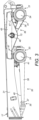
- FIG. 2 and 3 shows the chassis system 30 of the trailer 12.
- the chassis system 30 may comprise a tandem axle having two axles, namely a central axle 20 and a rear axle 21.
- the chassis system 30 may, however, have more than two axles, although for the purposes of this embodiment only two axles will be referred to.
- the ground engaging means 14 (shown in Figure 1 ) may be mounted by suitable mounting means 24 located at each end of the central axle 20 and rear axles 21 of the trailer 12.
- the ground engaging means 14 may provide support between the terrain 25 over which the articulated vehicle 10 travels and the tractor 11 and trailer 12.
- the ground engaging means 14 may be of any suitable type, for example wheels or tracks, and may be operably connected via the central axle 20 and rear axles 21 to, and thus receive power from, the power unit.
- Power may be transferred from the power unit, which may be located in the tractor 11, to one or both of the central axle 20 and rear axles 21 by a drive shaft (not shown) via the coupling 15, depending on whether one or both of the central axle 20 and rear axles 21 are driven axles.
- An end of the drive shaft may be operably connected to receive power from the coupling 15.
- Transmission devices (not shown), such as differentials or universal joints, may transfer torque from the drive shaft to the central axle 20 and rear axles 21.
- the central axle 20 and rear axles 21 may be attached to the chassis frame 17 by the chassis system 30.
- the chassis frame 17 has two longitudinal chassis members 31, which may be parallel, and at least two cross members 32 are attached between the two longitudinal chassis members 31.
- the chassis frame 17 has a spindle cross member 34, which may act as the primary cross member to stiffen the chassis frame 17, and which is attached between the two longitudinal chassis members 31.
- a central suspension frame 35 may extend between a cross member 32 located at a front of the chassis frame 17 and the central axle 20.
- a rear suspension frame 36 may extend between the spindle cross member 34 and the rear axle 21.
- the central suspension frame 35 and rear suspension frame 36 may be configured as A-frames, comprising a suspension frame head 37, a first arm 38 and a second arm 39.
- Each first arm 38 and second arm 39 may have a first arm end 40 and a second arm end 41.
- the first arm ends 40 of each first arm 38 and second arm 39 may be joined together at the suspension frame head 37 with the first arm 38 and second arm 39 extending outwardly from the suspension frame head 37 at an angle.
- the suspension frame heads 37 are pivotally attached to the respective cross member 32 and spindle cross member 34.
- the suspension frame head 37 of the central suspension frame 35 may be attached to the cross member 32 by means of a pivot bearing 49 attached to the cross member 32.
- the pivot bearing 49 may extend through a lug 50 attached to or formed in the suspension frame head 37.
- the second arm end 41 of the first arm 38 may be attached to the respective central axle 20 or rear axle 21 on one side of the chassis frame 17 and the second arm end 41 of the second arm 39 is attached the same central axle 20 or rear axle 21 on the other side of the chassis frame 17.
- a first equalizer beam 45 may be connected to, and extend between, the central axle 20 and rear axles 21 on one side of the chassis frame 17.
- a second equalizer beam 46 may be attached to, and extend, between the central axle 20 and rear axles 21 on the other side of the chassis frame 17.
- the first equalizer beam 45 and second equalizer beam 46 may be attached to the central axle 20 and rear axles 21 via resilient suspension mounts 47.
- the suspension mounts 47 may comprise a pad of elastomeric material, such as rubber, sandwiched between two mounting plates.
- the spindle cross member 34 comprises a main member 51 and a spindle end 52 located at either end of the main member 51.
- the main member 51 may be steel and formed by a casting process.
- the spindle ends 52 may be forged, for example from boron steel which is then direct (thru) hardened.
- Spindle caps may be located on the spindle ends 52. Manufacturing the main member 51 and spindle ends 52 using different materials and different manufacturing processes may allow the optimum construction in terms of balancing component strength in the areas subjected to the highest stresses against manufacturing costs. However the spindle cross member 34 may be manufactured as a single component.
- a middle section of the main member 51 has a middle section wall 61 which is at least partially curved and which defines a central cavity 53 and has an opening 62.
- the central cavity 53 may generally have a cup-like form. This may, for example, be C-shaped, U-shaped, hemispherical, or in the form of dome or an elongate parabolic dome.
- the thickness of the middle section wall 61 may taper from a central point towards the edges (which define the opening 62) in a transverse direction of the spindle cross member 34. As shown in Figure 5a , the thickness t 1 at the central point of the middle section wall 61 is more than the thickness t 4 at the edges of the middle section wall 61.
- Two bosses 56 may extend from the middle section wall 61 at a roof 54 of the dome into the central cavity 53 and the bosses 56 may be located one on either side of the dome vertex 55 and spaced apart in a longitudinal direction.
- the bosses 56 may define bores 58 which extend through the wall of the main member 51.
- tubular end sections 60 On either side of the middle section of the main member 51 and located along a longitudinal axis of the spindle cross member 34 are tubular end sections 60.
- the tubular end sections 60 which may be formed by extensions of the middle section wall 61, extend outwardly along the longitudinal axis of the spindle cross member 34.
- the tubular ends sections 60 may be separated from the central cavity 53 by a section of the middle section wall.
- the tubular end sections 60 may define hollow end cavities 59 which may be at least partially cylindrical and may be located so that the tubular end sections 60 open outwardly in a longitudinal direction.
- the thickness t 2 , t 3 of the walls of the tubular end sections 60 may be less than the thickness t 1 of the middle section wall 61 (see Figure 5 ). Additionally the thickness of the walls of the tubular end sections 60 may taper as they extend away from the middle section of the main member 51. As shown in Figure 5 the thickness t 3 is less than the thickness t 2 .
- the spindle ends 52 may comprise a first cylindrical end section 65, a middle conical section 66 and a second cylindrical end section 68, which has a larger diameter than the first cylindrical end section 65.
- a flange 67 may extend from the second cylindrical end section 68, which flange 67 may be sized to be inserted partially into an end cavity 59 of the tubular end sections 60 and secured therein, for example by welding.
- the longitudinal axis 57 of the spindle cross member 34 may extend through the centre of the spindle ends 52.
- the spindle cross member 34 may be affixed to the chassis frame 17 with the spindle ends 52 extending through apertures 70 in the longitudinal chassis members 31.
- the spindle cross member 34 is secured in position, for example by welding the second cylindrical end section 68 of the spindle ends 52 to the respective longitudinal chassis member 31 on the outside of chassis frame 17 and by welding the main member 51 to the respective longitudinal chassis member 31 on the inside of chassis frame 17.
- the first equalizer beam 45 and second equalizer beam 46 may be connected, one at each end, to the spindle cross member 34.
- the first equalizer beam 45 and second equalizer beam 46 may have apertures 71, located in which are bushings 48.
- the first cylindrical end sections 65 of the spindle ends 52 may extend through the bushings 48 and may be secured therein by means of a fixing 72 attached to the ends of the first cylindrical end sections 65.
- the bushings 48 may be conical in shape and may be made of an elastomeric material, such as rubber and may allow the first equalizer beam 45 and second equalizer beam 46 to rotate relative to the spindle cross member 34 and the chassis frame 17.
- the rear suspension frame 36 is pivotally attached to the spindle cross member 34, which may be by means of a straddle bearing 73, which may be a spherical plain bearing, the inner ring of which may comprise a pin.
- the straddle bearing 73 may be pressed into a lug 50 formed in the suspension frame head 37 of the rear suspension frame 36.
- the straddle bearing 73 may be attached to the bosses 56 inside the central cavity 53 of the spindle cross member 34 by means of fixings 74, such as bolts.
- the fixings 74 may extend through the bores 58 in the bosses 56.
- the length of the bosses 56 and the depth of the central cavity 53 may be selected such that, when the rear suspension frame 36 is attached to the spindle cross member 34, the axis of the straddle bearing 73, and therefore the lug 50, is coaxial with the longitudinal axis 57 of the spindle cross member 34.
- the spindle cross member 34 envelops the lug 50.
- the spindle cross member 34 may be the primary structural cross member of the chassis frame 17 which may be subjected to significant forces, which it needs to be able to withstand so as to reduce stress in the chassis frame 17.
- the main loading experienced by the spindle cross member 34 may be from the axle loads transmitted to the spindle ends 52 via the first equalizer beam 45 and second equalizer beam 46. These forces may induce a bending moment across the spindle cross member 34 and torsion into the longitudinal chassis members 31 of the chassis frame 17.
- the spindle cross member 34 may also experience loading from the rear axle 21 via the rear suspension frame 36.
- the geometry of the main member 51 may not only provide a stiff load bearing structure which resists the induced bending moment to minimise damage during use, but may also minimise the risk of defects during casting.
- the "envelope" provided by the cup-like middle section wall 61 defining the central cavity 53 surrounds the suspension frame head 37 and may resist the bending moment across the spindle cross member 34, induced by the axle loads on the spindle ends 52. This may be achieved by maximising the section/ stiffness within the geometric constraints imposed by the rear suspension frame 36; the stiffness provided by the tubular end sections 60 is maintained despite the constraints of the rear suspension frame 36, through the blending of the geometry into the curved middle section wall 61.
- the effect of the section change from the tubular end sections 60 to the middle section wall 61 in the midsection of the main member 51, combined with the local longitudinal and transverse wall tapering, t 2 to t 3 and t 1 to t 4 , may result in a general increase in wall thickness towards the centre of the main member 51. This may help to avoid shrinkage defects during the casting process as it may allow directional solidification towards the centre of the main member 51 where a riser is formed in the casting.
- the riser may be machined away as a part of the finishing process and the resulting flat machined surface may be used to receive the heads of the fixings 74 which may secure the straddle bearing 73 to the bosses 56 inside the central cavity 53 of the spindle cross member 34.
- the configuration of the spindle cross member 34 may also be such as to enable the axis of the straddle bearing 73, and therefore the pivot axis of the rear suspension frame 36, to be coaxial with the longitudinal axis 57 of the spindle cross member 34. This may be advantageous in that this enables the rear axle 21 to pivot through the same arc as the first equalizer beam 45 and second equalizer beam 46 rather than following a divergent arc, which may reduce the shearing force on the suspension mounts 47. This may assist in extending the life of the suspension mounts 47.
Landscapes
- Engineering & Computer Science (AREA)
- Mechanical Engineering (AREA)
- Chemical & Material Sciences (AREA)
- Combustion & Propulsion (AREA)
- Transportation (AREA)
- Vehicle Body Suspensions (AREA)
- Body Structure For Vehicles (AREA)
Description
- This disclosure is directed towards a chassis system and more particularly to a spindle cross member for the chassis system which is suitable for an articulated vehicle.
- Many vehicles and work machines, such as articulated trucks, excavators, dozers, loaders and the like, may have a centre of mass which is relatively high above the ground. This may be as a result of loading during operation, for example where a dump body holds a large mass of material. Work machines are often equipped with work tools which can be raised for safety when not in use and when the vehicle is travelling, which also affects the centre of mass of the vehicle. Such work machines are also typically operated on rough and uneven terrain. As a result, there is a risk that the work machine may tip over as it travels over uneven terrain.
- This risk is increased for articulated vehicles, in that these typically comprise a tractor (in which the power unit is usually mounted) and a trailer (which may have a container for holding a mass of material or goods for transportation) connected to one another via an oscillating hitch joint. The oscillating hitch joint enables the tractor and trailer to roll and yaw relative to one another. When operated on uneven terrain, one of the tractor and trailer s may become positioned at an unsafe roll and/or yaw angle and may cause the entire machine to turn over. Alternatively, if the articulated vehicle has an open container, such as a bucket or body mounted on the trailer, any materials or goods held in the open container may fall out when one of the tractor and trailer is positioned above certain roll and/or yaw angle thresholds.
- The chassis system of such articulated vehicles may be designed to help reduce the likelihood of this from occurring as well as improving the vehicle ride dynamics. The chassis system of an articulated vehicle typically comprises a tandem axle, which provides a greater weight capacity than a single axle. A tandem axle comprises two axles one or both of the central and rear axles may be driven axles. The chassis system of tandem drive axles utilise special suspension arrangements which permits flexibility between the axles, but which are able to withstand hard operating conditions. One such type of suspension is an equalizing beam suspension, which may be of the leaf spring or rubber load cushion type. Equalizing beams link the suspensions of the adjacent axles and use the lever principle to distribute the load across the axles to reduce the effect of uneven terrain. Equalizing beam systems may also help to lower the centre of gravity of the axle load to provide better stability. Equalizing suspension systems may also include a torque rod to restrict lateral movement of the axles and to keep them centred, to further provide greater stability and roll stiffness.
- In an articulated vehicle, the chassis frame has to provide the required geometry for the suspension and body layout, whilst also withstanding the loading from these systems. The oscillating hitch joint significantly reduces frame torsion compared to other vehicles. However, the chassis frame does still experience significant beam torsion, due to the effect of the axle loads being applied via the equalizing beams. A primary chassis cross member may therefore be provided, which has the function of stiffening the chassis to resist this loading, in addition to mounting and locating the rear suspension components in the required positions.
-
WO-99-04991 - The disclosure provides a spindle cross member for a chassis system for a vehicle comprising:
- a main member, having a middle section and tubular end sections, said middle section having an at least partially curved middle section wall which defines a cavity with an opening for receiving a head of a suspension frame of the chassis system, and said tubular end sections being located at each end of the middle section located along a longitudinal axis of the spindle cross member; and
- means for pivotally attaching the head of the suspension frame to the middle section wall within the cavity.
- The disclosure further provides a chassis system comprising a chassis frame and a suspension frame, said chassis frame comprising at least two longitudinal members and a plurality of cross members, at least one of said cross members being the spindle cross member as claimed in any one of the preceding claims and said suspension frame having a suspension frame head, wherein the suspension frame head is attached to the spindle cross member and is at least partially enveloped by the middle section wall.
- The disclosure also provides a vehicle comprising a tractor and a trailer connected to the tractor by an articulated joint, said trailer having at least one axle, wherein the at least one axle is attached to the aforementioned chassis system.
-
-
Figure 1 is a side elevation of an exemplary articulated vehicle comprising the chassis system and spindle cross member of the present disclosure; -
Figure 2 is a plan view of the chassis system of the trailer of the vehicle ofFigure 1 ; -
Figure 3 is a side elevation of part of the chassis system ofFigure 2 ; -
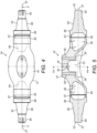
Figure 4 is a plan view of the spindle cross member of the chassis system ofFigure 2 ; -
Figure 5 is a cross sectional side elevation of the spindle cross member ofFigure 4 on the line V-V; -
Figure 5a is a cross sectional end elevation of the spindle cross member ofFigure 5 on the line Va-Va; -
Figure 6 is a perspective view of a section of the underside of the spindle cross member ofFigure 4 ; and -
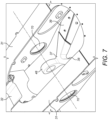
Figure 7 is an perspective view of a section of the chassis ofFigure 2 with the spindle cross member omitted to show the suspension frame head of the rear suspension member; - The present disclosure is generally directed towards a chassis system having a spindle cross member as the primary cross member, which is suitable for a vehicle and in particular for an articulated vehicle. Although the following description only describes an articulated
vehicle 10, the chassis system may be used in any vehicle. -
Figure 1 illustrates an exemplary articulatedvehicle 10 in which the chassis system of the present disclosure may be used. The articulatedvehicle 10 may comprise atractor 11 and atrailer 12. Thetractor 11 may be a tractor unit and may comprise acab 13 and a power unit (not shown). The power unit may be of any suitable type, such as an internal combustion engine, a micro-turbine or an electric motor. A front axle (not shown) may be provided to support thetractor 11 having one or moreground engaging means 14, such as wheels, mounted at either end of the front axle. Thetractor 11 may comprise more than one axle and more than twoground engaging means 14 attached to each axle. - The
tractor 11 may be connected to thetrailer 12 via acoupling 15, which may be an articulation joint. Thecoupling 15 may allow thetractor 11 andtrailer 12 to be orientated at a different yaw and/or roll angle to each other frame. The yaw angle of thetractor 11 may be different to the yaw angle of thetrailer 12 about anarticulation axis 16. The articulatedvehicle 10 may be steered by adjusting the yaw angle of thetractor 11 andtrailer 12 about thearticulation axis 16 utilising actuators (not shown), for example hydraulic cylinders, attached to each of thetractor 11 andtrailer 12 on either side of thecoupling 15. - The
trailer 12 may comprise achassis system 30 and abody 18 adapted to carry a load, such as a dump or ejector body. Thechassis system 30 may comprise achassis frame 17 and thebody 18 may be attached to thechassis frame 17 at a pivot point (not shown). A tipping system may be provided to rotate thebody 18 about the pivot point. The tipping system may comprise at least onehydraulic actuator 19 connected to thebody 18 and thechassis frame 17. Thebody 18 may comprise an ejector mechanism, having an actuator which may move a plate within thebody 18 to eject any material contained therein. -
Figure 2 and3 shows thechassis system 30 of thetrailer 12. Thechassis system 30 may comprise a tandem axle having two axles, namely acentral axle 20 and arear axle 21. Thechassis system 30 may, however, have more than two axles, although for the purposes of this embodiment only two axles will be referred to. The ground engaging means 14 (shown inFigure 1 ) may be mounted by suitable mounting means 24 located at each end of thecentral axle 20 andrear axles 21 of thetrailer 12. Theground engaging means 14 may provide support between theterrain 25 over which the articulatedvehicle 10 travels and thetractor 11 andtrailer 12. Theground engaging means 14 may be of any suitable type, for example wheels or tracks, and may be operably connected via thecentral axle 20 andrear axles 21 to, and thus receive power from, the power unit. - Power may be transferred from the power unit, which may be located in the
tractor 11, to one or both of thecentral axle 20 andrear axles 21 by a drive shaft (not shown) via thecoupling 15, depending on whether one or both of thecentral axle 20 andrear axles 21 are driven axles. An end of the drive shaft may be operably connected to receive power from thecoupling 15. Transmission devices (not shown), such as differentials or universal joints, may transfer torque from the drive shaft to thecentral axle 20 andrear axles 21. - The
central axle 20 andrear axles 21 may be attached to thechassis frame 17 by thechassis system 30. Thechassis frame 17 has twolongitudinal chassis members 31, which may be parallel, and at least twocross members 32 are attached between the twolongitudinal chassis members 31. Thechassis frame 17 has aspindle cross member 34, which may act as the primary cross member to stiffen thechassis frame 17, and which is attached between the twolongitudinal chassis members 31. Acentral suspension frame 35 may extend between across member 32 located at a front of thechassis frame 17 and thecentral axle 20. Arear suspension frame 36 may extend between thespindle cross member 34 and therear axle 21. Thecentral suspension frame 35 andrear suspension frame 36 may be configured as A-frames, comprising asuspension frame head 37, afirst arm 38 and asecond arm 39. Eachfirst arm 38 andsecond arm 39 may have afirst arm end 40 and asecond arm end 41. The first arm ends 40 of eachfirst arm 38 andsecond arm 39 may be joined together at thesuspension frame head 37 with thefirst arm 38 andsecond arm 39 extending outwardly from thesuspension frame head 37 at an angle. The suspension frame heads 37 are pivotally attached to therespective cross member 32 andspindle cross member 34. Thesuspension frame head 37 of thecentral suspension frame 35 may be attached to thecross member 32 by means of a pivot bearing 49 attached to thecross member 32. Thepivot bearing 49 may extend through alug 50 attached to or formed in thesuspension frame head 37. The attachment of therear suspension frame 36 to thespindle cross member 34 will be described below. - The
second arm end 41 of thefirst arm 38 may be attached to the respectivecentral axle 20 orrear axle 21 on one side of thechassis frame 17 and thesecond arm end 41 of thesecond arm 39 is attached the samecentral axle 20 orrear axle 21 on the other side of thechassis frame 17. - As shown in
Figures 2 and3 , afirst equalizer beam 45 may be connected to, and extend between, thecentral axle 20 andrear axles 21 on one side of thechassis frame 17. Asecond equalizer beam 46 may be attached to, and extend, between thecentral axle 20 andrear axles 21 on the other side of thechassis frame 17. Thefirst equalizer beam 45 andsecond equalizer beam 46 may be attached to thecentral axle 20 andrear axles 21 via resilient suspension mounts 47. The suspension mounts 47 may comprise a pad of elastomeric material, such as rubber, sandwiched between two mounting plates. - As shown in
Figures 4 and 5 , thespindle cross member 34 comprises amain member 51 and aspindle end 52 located at either end of themain member 51. Themain member 51 may be steel and formed by a casting process. The spindle ends 52 may be forged, for example from boron steel which is then direct (thru) hardened. Spindle caps may be located on the spindle ends 52. Manufacturing themain member 51 and spindle ends 52 using different materials and different manufacturing processes may allow the optimum construction in terms of balancing component strength in the areas subjected to the highest stresses against manufacturing costs. However thespindle cross member 34 may be manufactured as a single component. - A middle section of the
main member 51 has amiddle section wall 61 which is at least partially curved and which defines acentral cavity 53 and has an opening 62. Thecentral cavity 53 may generally have a cup-like form. This may, for example, be C-shaped, U-shaped, hemispherical, or in the form of dome or an elongate parabolic dome. The thickness of themiddle section wall 61 may taper from a central point towards the edges (which define the opening 62) in a transverse direction of thespindle cross member 34. As shown inFigure 5a , the thickness t1 at the central point of themiddle section wall 61 is more than the thickness t4 at the edges of themiddle section wall 61. Twobosses 56 may extend from themiddle section wall 61 at aroof 54 of the dome into thecentral cavity 53 and thebosses 56 may be located one on either side of thedome vertex 55 and spaced apart in a longitudinal direction. Thebosses 56 may definebores 58 which extend through the wall of themain member 51. - On either side of the middle section of the
main member 51 and located along a longitudinal axis of thespindle cross member 34 aretubular end sections 60. Thetubular end sections 60, which may be formed by extensions of themiddle section wall 61, extend outwardly along the longitudinal axis of thespindle cross member 34. The tubular endssections 60 may be separated from thecentral cavity 53 by a section of the middle section wall. Thetubular end sections 60 may definehollow end cavities 59 which may be at least partially cylindrical and may be located so that thetubular end sections 60 open outwardly in a longitudinal direction. The thickness t2, t3 of the walls of thetubular end sections 60 may be less than the thickness t1 of the middle section wall 61 (seeFigure 5 ). Additionally the thickness of the walls of thetubular end sections 60 may taper as they extend away from the middle section of themain member 51. As shown inFigure 5 the thickness t3 is less than the thickness t2. - The spindle ends 52 may comprise a first
cylindrical end section 65, a middleconical section 66 and a secondcylindrical end section 68, which has a larger diameter than the firstcylindrical end section 65. Aflange 67 may extend from the secondcylindrical end section 68, which flange 67 may be sized to be inserted partially into anend cavity 59 of thetubular end sections 60 and secured therein, for example by welding. Thelongitudinal axis 57 of thespindle cross member 34 may extend through the centre of the spindle ends 52. - The
spindle cross member 34 may be affixed to thechassis frame 17 with the spindle ends 52 extending throughapertures 70 in thelongitudinal chassis members 31. Thespindle cross member 34 is secured in position, for example by welding the secondcylindrical end section 68 of the spindle ends 52 to the respectivelongitudinal chassis member 31 on the outside ofchassis frame 17 and by welding themain member 51 to the respectivelongitudinal chassis member 31 on the inside ofchassis frame 17. - The
first equalizer beam 45 andsecond equalizer beam 46 may be connected, one at each end, to thespindle cross member 34. Thefirst equalizer beam 45 andsecond equalizer beam 46 may haveapertures 71, located in which are bushings 48. The firstcylindrical end sections 65 of the spindle ends 52 may extend through thebushings 48 and may be secured therein by means of a fixing 72 attached to the ends of the firstcylindrical end sections 65. Thebushings 48 may be conical in shape and may be made of an elastomeric material, such as rubber and may allow thefirst equalizer beam 45 andsecond equalizer beam 46 to rotate relative to thespindle cross member 34 and thechassis frame 17. - The
rear suspension frame 36 is pivotally attached to thespindle cross member 34, which may be by means of a straddle bearing 73, which may be a spherical plain bearing, the inner ring of which may comprise a pin. The straddle bearing 73 may be pressed into alug 50 formed in thesuspension frame head 37 of therear suspension frame 36. The straddle bearing 73 may be attached to thebosses 56 inside thecentral cavity 53 of thespindle cross member 34 by means offixings 74, such as bolts. Thefixings 74 may extend through thebores 58 in thebosses 56. The length of thebosses 56 and the depth of thecentral cavity 53 may be selected such that, when therear suspension frame 36 is attached to thespindle cross member 34, the axis of the straddle bearing 73, and therefore thelug 50, is coaxial with thelongitudinal axis 57 of thespindle cross member 34. In addition, thespindle cross member 34 envelops thelug 50. - The
spindle cross member 34 may be the primary structural cross member of thechassis frame 17 which may be subjected to significant forces, which it needs to be able to withstand so as to reduce stress in thechassis frame 17. The main loading experienced by thespindle cross member 34 may be from the axle loads transmitted to the spindle ends 52 via thefirst equalizer beam 45 andsecond equalizer beam 46. These forces may induce a bending moment across thespindle cross member 34 and torsion into thelongitudinal chassis members 31 of thechassis frame 17. Thespindle cross member 34 may also experience loading from therear axle 21 via therear suspension frame 36. The geometry of themain member 51 may not only provide a stiff load bearing structure which resists the induced bending moment to minimise damage during use, but may also minimise the risk of defects during casting. The "envelope" provided by the cup-likemiddle section wall 61 defining thecentral cavity 53 surrounds thesuspension frame head 37 and may resist the bending moment across thespindle cross member 34, induced by the axle loads on the spindle ends 52. This may be achieved by maximising the section/ stiffness within the geometric constraints imposed by therear suspension frame 36; the stiffness provided by thetubular end sections 60 is maintained despite the constraints of therear suspension frame 36, through the blending of the geometry into the curvedmiddle section wall 61. The effect of the section change from thetubular end sections 60 to themiddle section wall 61 in the midsection of themain member 51, combined with the local longitudinal and transverse wall tapering, t2 to t3 and t1 to t4, may result in a general increase in wall thickness towards the centre of themain member 51. This may help to avoid shrinkage defects during the casting process as it may allow directional solidification towards the centre of themain member 51 where a riser is formed in the casting. The riser may be machined away as a part of the finishing process and the resulting flat machined surface may be used to receive the heads of thefixings 74 which may secure the straddle bearing 73 to thebosses 56 inside thecentral cavity 53 of thespindle cross member 34. - The configuration of the
spindle cross member 34 may also be such as to enable the axis of the straddle bearing 73, and therefore the pivot axis of therear suspension frame 36, to be coaxial with thelongitudinal axis 57 of thespindle cross member 34. This may be advantageous in that this enables therear axle 21 to pivot through the same arc as thefirst equalizer beam 45 andsecond equalizer beam 46 rather than following a divergent arc, which may reduce the shearing force on the suspension mounts 47. This may assist in extending the life of the suspension mounts 47.
Claims (12)
- A spindle cross member (34) for a chassis system (30) for a vehicle (10) comprising:a main member (51), having a middle section and end sections (60);characterised in that said end sections (60) are tubular and that said middle section having an at least partially curved middle section wall (61) which defines a cavity (53) with an opening for receiving a head (37) of a suspension frame (36) of the chassis system (30), and said tubular end sections (60) being located at each end of the middle section located along a longitudinal axis (57) of the spindle cross member (34); andin that means (73) are provided for pivotally attaching the head (37) of the suspension frame (36) to the middle section wall (61) within the cavity (53).
- A spindle cross member (34) as claimed in claim 1, wherein the middle section wall (61) extends outwardly along the longitudinal axis (57) of the spindle cross member (34) to form the tubular end sections (60).
- A spindle cross member (34) as claimed in claim 1 or claim 2 wherein a thickness of the middle section wall (61) tapers from a central point along the longitudinal axis (57) of the spindle cross member (34) towards edges of the middle section wall (61) in a plane perpendicular to the longitudinal axis (57) of the spindle cross member (34).
- A spindle cross member (34) as claimed in any one of the preceding claims wherein the tubular end sections (60) have walls and a thickness of the tubular end section walls tapers as they extend away from the middle section.
- A spindle cross member (34) as claimed in any one of the preceding claims in which the tubular end sections (60) are at least partly cylindrical.
- A spindle cross member (34) as claimed in any one of the preceding claims further comprising a conical spindle end (52) affixed to an end of each tubular end section (60).
- A spindle cross member (34) as claimed in claim 6 wherein the spindle ends (52) comprise a first cylindrical end section (65), a middle conical section (66) and a second cylindrical end section (68), the second cylindrical end section (68) having a larger diameter than the first cylindrical end section (65), wherein a flange (67) extends from the second cylindrical end section (68), which flange (67) is inserted partially into an end of the tubular end section (60).
- A spindle cross member (34) as claimed in any one of the preceding claims wherein the means (73) for pivotally attaching a head (37) of a suspension frame (36) to the middle section wall (61) within the cavity (53) is a straddle bearing.
- A chassis system (30) comprising a chassis frame (17) and a suspension frame (36), said chassis frame (17) comprising at least two longitudinal members (31) and a plurality of cross members (32,34), at least one of said cross members (32,34) being the spindle cross member (34) as claimed in any one of the preceding claims and said suspension frame (36) having a suspension frame head (37), wherein the suspension frame head (37) is attached to the spindle cross member (34) and is at least partially enveloped by the middle section wall (61).
- A chassis system (30) as claimed in claim 9 wherein the suspension frame head (37) is substantially co-axial with the longitudinal axis (57) of the spindle cross member (34).
- A chassis system (30) as claimed in claim 9 or claim 10 wherein the suspension frame (36) is an A-frame.
- A vehicle (10) comprising a tractor (11) and a trailer (12) connected to the tractor (11) by an articulated joint (15), said trailer (12) having at least one axle (21), wherein the at least one axle (21) is attached to the chassis system (30) of any one of claims 9 to 11.
Applications Claiming Priority (1)
| Application Number | Priority Date | Filing Date | Title |
|---|---|---|---|
| GB1905029.3A GB2582937B (en) | 2019-04-09 | 2019-04-09 | Chassis system |
Publications (2)
| Publication Number | Publication Date |
|---|---|
| EP3722117A1 EP3722117A1 (en) | 2020-10-14 |
| EP3722117B1 true EP3722117B1 (en) | 2024-10-02 |
Family
ID=66809472
Family Applications (1)
| Application Number | Title | Priority Date | Filing Date |
|---|---|---|---|
| EP20168103.8A Active EP3722117B1 (en) | 2019-04-09 | 2020-04-03 | Chassis system |
Country Status (3)
| Country | Link |
|---|---|
| US (1) | US11370491B2 (en) |
| EP (1) | EP3722117B1 (en) |
| GB (1) | GB2582937B (en) |
Families Citing this family (1)
| Publication number | Priority date | Publication date | Assignee | Title |
|---|---|---|---|---|
| US12441143B2 (en) | 2023-11-13 | 2025-10-14 | Caterpillar Inc. | Multi-link front suspension for an underground articulated dump truck |
Family Cites Families (18)
| Publication number | Priority date | Publication date | Assignee | Title |
|---|---|---|---|---|
| US3388923A (en) | 1965-09-27 | 1968-06-18 | Maynard Wade | Kingpin assembly and method for using same |
| US4415179A (en) * | 1981-04-15 | 1983-11-15 | Marinelli Joseph A | Axle and air bag suspension |
| DE4129538C2 (en) * | 1991-09-05 | 1993-11-18 | Porsche Ag | Subframe for a motor vehicle |
| US5366035A (en) * | 1992-02-27 | 1994-11-22 | Mitsubishi Jidosha Kogyo Kabushiki Kaisha | Rear wheel steering device and method for rear wheel steering |
| US5971425A (en) | 1997-07-22 | 1999-10-26 | Caterpillar Inc. | Suspension system for a load carrying machine |
| US6470990B1 (en) * | 2000-07-26 | 2002-10-29 | Daniel E. Panoz | Extruded vehicle chassis and method of making a chassis |
| US20070138755A1 (en) * | 2005-12-16 | 2007-06-21 | Copsey Charles R | Hybrid-response for suspension system |
| DE102006045864A1 (en) | 2006-09-28 | 2008-04-03 | Daimler Ag | Rigid axle suspension for commercial motor vehicle, has fastening belt whose centre area, which is plus/minus thirty percent of length of semi-training arms, is arranged between front and rear handle bar center joints |
| DE102007008325A1 (en) * | 2007-02-16 | 2008-08-21 | Zf Friedrichshafen Ag | Rigid axle for a commercial vehicle |
| US7866231B2 (en) * | 2008-08-19 | 2011-01-11 | American Axle & Manufacturing, Inc. | Axle assembly having gasket that shields an opening |
| JP4864153B2 (en) | 2010-06-30 | 2012-02-01 | 株式会社小松製作所 | Off-road truck with a rubber spring device |
| DE102012011797A1 (en) * | 2011-07-05 | 2013-01-10 | Ksm Castings Group Gmbh | axle |
| FR2991956B1 (en) | 2012-06-18 | 2014-07-04 | Alstom Transport Sa | BOGIE OF A RAILWAY VEHICLE HAVING IMPROVED SUSPENSIONS, IN PARTICULAR FOR A LOW FLOOR TRAMWAY |
| US9549046B1 (en) | 2013-02-20 | 2017-01-17 | The Boeing Company | Methods and systems for logging time with a mobile computing device |
| DE102014011803A1 (en) * | 2014-08-09 | 2016-02-11 | Man Truck & Bus Ag | Air spring carrier for an air-suspended axle of a commercial vehicle |
| CN206914434U (en) * | 2017-06-28 | 2018-01-23 | 徐州徐工矿山机械有限公司 | A kind of carriage of mining self-unloading vehicle gantry beam |
| US11198473B2 (en) * | 2018-02-20 | 2021-12-14 | Mazda Motor Corporation | Subframe structure |
| US11207934B2 (en) * | 2018-11-16 | 2021-12-28 | Saf-Holland, Inc. | Vehicle suspension assembly |
-
2019
- 2019-04-09 GB GB1905029.3A patent/GB2582937B/en active Active
-
2020
- 2020-03-16 US US16/819,729 patent/US11370491B2/en active Active
- 2020-04-03 EP EP20168103.8A patent/EP3722117B1/en active Active
Also Published As
| Publication number | Publication date |
|---|---|
| GB2582937B (en) | 2021-05-12 |
| US20200324819A1 (en) | 2020-10-15 |
| GB2582937A (en) | 2020-10-14 |
| US11370491B2 (en) | 2022-06-28 |
| EP3722117A1 (en) | 2020-10-14 |
| GB201905029D0 (en) | 2019-05-22 |
Similar Documents
| Publication | Publication Date | Title |
|---|---|---|
| US5897123A (en) | Tag axle pivot | |
| EP2429840B1 (en) | Suspension system for heavy and vocational vehicles | |
| EP0814964B1 (en) | Large dump truck suspension | |
| EP2938530B1 (en) | Steering intermediate arm | |
| US8523203B1 (en) | Trailing axle suspension system | |
| JPH0796372B2 (en) | All-wheel drive off-road vehicle | |
| RU2487018C2 (en) | Stabiliser system for wheel axle suspension, and stabiliser | |
| EP3215413B1 (en) | Attachment device for track support beam of tracked vehicle | |
| US8523202B1 (en) | Trailing axle suspension system | |
| EP0928251B1 (en) | Suspension system for a load carrying machine | |
| US20100231025A1 (en) | Adjustable crawler vehicle | |
| EP3722117B1 (en) | Chassis system | |
| CA3154550C (en) | Space frame front upper body support and frame connection | |
| US7168718B2 (en) | Vehicle suspension arrangement and vehicle provided with such a suspension | |
| EP0909668B1 (en) | Structure for supporting fluid pressure cylinders used to control pivoting of vehicle axles | |
| US11021190B2 (en) | Suspension system for a vehicle | |
| US20230027448A1 (en) | Frame Steered Vehicle | |
| US12441143B2 (en) | Multi-link front suspension for an underground articulated dump truck | |
| CN221292846U (en) | Chassis and dumper | |
| EP3959116B1 (en) | Vehicle chassis having twin walled beams with suspension mounting structure | |
| US11292311B2 (en) | Space frame front upper suspension connection | |
| EP4069574A1 (en) | Frame steered vehicle | |
| WO2014040836A1 (en) | Suspension system | |
| CA3154640A1 (en) | Space frame center lower frame connection | |
| WO2001060646A1 (en) | Front suspension system for a wheeled vehicle |
Legal Events
| Date | Code | Title | Description |
|---|---|---|---|
| PUAI | Public reference made under article 153(3) epc to a published international application that has entered the european phase |
Free format text: ORIGINAL CODE: 0009012 |
|
| STAA | Information on the status of an ep patent application or granted ep patent |
Free format text: STATUS: THE APPLICATION HAS BEEN PUBLISHED |
|
| AK | Designated contracting states |
Kind code of ref document: A1 Designated state(s): AL AT BE BG CH CY CZ DE DK EE ES FI FR GB GR HR HU IE IS IT LI LT LU LV MC MK MT NL NO PL PT RO RS SE SI SK SM TR |
|
| AX | Request for extension of the european patent |
Extension state: BA ME |
|
| STAA | Information on the status of an ep patent application or granted ep patent |
Free format text: STATUS: REQUEST FOR EXAMINATION WAS MADE |
|
| 17P | Request for examination filed |
Effective date: 20210408 |
|
| RBV | Designated contracting states (corrected) |
Designated state(s): AL AT BE BG CH CY CZ DE DK EE ES FI FR GB GR HR HU IE IS IT LI LT LU LV MC MK MT NL NO PL PT RO RS SE SI SK SM TR |
|
| STAA | Information on the status of an ep patent application or granted ep patent |
Free format text: STATUS: EXAMINATION IS IN PROGRESS |
|
| 17Q | First examination report despatched |
Effective date: 20220609 |
|
| GRAP | Despatch of communication of intention to grant a patent |
Free format text: ORIGINAL CODE: EPIDOSNIGR1 |
|
| STAA | Information on the status of an ep patent application or granted ep patent |
Free format text: STATUS: GRANT OF PATENT IS INTENDED |
|
| INTG | Intention to grant announced |
Effective date: 20240408 |
|
| GRAS | Grant fee paid |
Free format text: ORIGINAL CODE: EPIDOSNIGR3 |
|
| P01 | Opt-out of the competence of the unified patent court (upc) registered |
Free format text: CASE NUMBER: APP_41027/2024 Effective date: 20240710 |
|
| GRAA | (expected) grant |
Free format text: ORIGINAL CODE: 0009210 |
|
| STAA | Information on the status of an ep patent application or granted ep patent |
Free format text: STATUS: THE PATENT HAS BEEN GRANTED |
|
| AK | Designated contracting states |
Kind code of ref document: B1 Designated state(s): AL AT BE BG CH CY CZ DE DK EE ES FI FR GB GR HR HU IE IS IT LI LT LU LV MC MK MT NL NO PL PT RO RS SE SI SK SM TR |
|
| REG | Reference to a national code |
Ref country code: GB Ref legal event code: FG4D |
|
| REG | Reference to a national code |
Ref country code: CH Ref legal event code: EP |
|
| REG | Reference to a national code |
Ref country code: IE Ref legal event code: FG4D |
|
| REG | Reference to a national code |
Ref country code: DE Ref legal event code: R096 Ref document number: 602020038574 Country of ref document: DE |
|
| REG | Reference to a national code |
Ref country code: SE Ref legal event code: TRGR |
|
| REG | Reference to a national code |
Ref country code: LT Ref legal event code: MG9D |
|
| REG | Reference to a national code |
Ref country code: NL Ref legal event code: MP Effective date: 20241002 |
|
| REG | Reference to a national code |
Ref country code: AT Ref legal event code: MK05 Ref document number: 1728223 Country of ref document: AT Kind code of ref document: T Effective date: 20241002 |
|
| PG25 | Lapsed in a contracting state [announced via postgrant information from national office to epo] |
Ref country code: NL Free format text: LAPSE BECAUSE OF FAILURE TO SUBMIT A TRANSLATION OF THE DESCRIPTION OR TO PAY THE FEE WITHIN THE PRESCRIBED TIME-LIMIT Effective date: 20241002 |
|
| PG25 | Lapsed in a contracting state [announced via postgrant information from national office to epo] |
Ref country code: NL Free format text: LAPSE BECAUSE OF FAILURE TO SUBMIT A TRANSLATION OF THE DESCRIPTION OR TO PAY THE FEE WITHIN THE PRESCRIBED TIME-LIMIT Effective date: 20241002 |
|
| PG25 | Lapsed in a contracting state [announced via postgrant information from national office to epo] |
Ref country code: HR Free format text: LAPSE BECAUSE OF FAILURE TO SUBMIT A TRANSLATION OF THE DESCRIPTION OR TO PAY THE FEE WITHIN THE PRESCRIBED TIME-LIMIT Effective date: 20241002 Ref country code: IS Free format text: LAPSE BECAUSE OF FAILURE TO SUBMIT A TRANSLATION OF THE DESCRIPTION OR TO PAY THE FEE WITHIN THE PRESCRIBED TIME-LIMIT Effective date: 20250202 Ref country code: PT Free format text: LAPSE BECAUSE OF FAILURE TO SUBMIT A TRANSLATION OF THE DESCRIPTION OR TO PAY THE FEE WITHIN THE PRESCRIBED TIME-LIMIT Effective date: 20250203 |
|
| PG25 | Lapsed in a contracting state [announced via postgrant information from national office to epo] |
Ref country code: FI Free format text: LAPSE BECAUSE OF FAILURE TO SUBMIT A TRANSLATION OF THE DESCRIPTION OR TO PAY THE FEE WITHIN THE PRESCRIBED TIME-LIMIT Effective date: 20241002 |
|
| PG25 | Lapsed in a contracting state [announced via postgrant information from national office to epo] |
Ref country code: BG Free format text: LAPSE BECAUSE OF FAILURE TO SUBMIT A TRANSLATION OF THE DESCRIPTION OR TO PAY THE FEE WITHIN THE PRESCRIBED TIME-LIMIT Effective date: 20241002 |
|
| PG25 | Lapsed in a contracting state [announced via postgrant information from national office to epo] |
Ref country code: ES Free format text: LAPSE BECAUSE OF FAILURE TO SUBMIT A TRANSLATION OF THE DESCRIPTION OR TO PAY THE FEE WITHIN THE PRESCRIBED TIME-LIMIT Effective date: 20241002 |
|
| PG25 | Lapsed in a contracting state [announced via postgrant information from national office to epo] |
Ref country code: NO Free format text: LAPSE BECAUSE OF FAILURE TO SUBMIT A TRANSLATION OF THE DESCRIPTION OR TO PAY THE FEE WITHIN THE PRESCRIBED TIME-LIMIT Effective date: 20250102 |
|
| PG25 | Lapsed in a contracting state [announced via postgrant information from national office to epo] |
Ref country code: AT Free format text: LAPSE BECAUSE OF FAILURE TO SUBMIT A TRANSLATION OF THE DESCRIPTION OR TO PAY THE FEE WITHIN THE PRESCRIBED TIME-LIMIT Effective date: 20241002 Ref country code: LV Free format text: LAPSE BECAUSE OF FAILURE TO SUBMIT A TRANSLATION OF THE DESCRIPTION OR TO PAY THE FEE WITHIN THE PRESCRIBED TIME-LIMIT Effective date: 20241002 Ref country code: GR Free format text: LAPSE BECAUSE OF FAILURE TO SUBMIT A TRANSLATION OF THE DESCRIPTION OR TO PAY THE FEE WITHIN THE PRESCRIBED TIME-LIMIT Effective date: 20250103 |
|
| PG25 | Lapsed in a contracting state [announced via postgrant information from national office to epo] |
Ref country code: CZ Free format text: LAPSE BECAUSE OF FAILURE TO SUBMIT A TRANSLATION OF THE DESCRIPTION OR TO PAY THE FEE WITHIN THE PRESCRIBED TIME-LIMIT Effective date: 20241002 Ref country code: PL Free format text: LAPSE BECAUSE OF FAILURE TO SUBMIT A TRANSLATION OF THE DESCRIPTION OR TO PAY THE FEE WITHIN THE PRESCRIBED TIME-LIMIT Effective date: 20241002 |
|
| PG25 | Lapsed in a contracting state [announced via postgrant information from national office to epo] |
Ref country code: RS Free format text: LAPSE BECAUSE OF FAILURE TO SUBMIT A TRANSLATION OF THE DESCRIPTION OR TO PAY THE FEE WITHIN THE PRESCRIBED TIME-LIMIT Effective date: 20250102 |
|
| PG25 | Lapsed in a contracting state [announced via postgrant information from national office to epo] |
Ref country code: SM Free format text: LAPSE BECAUSE OF FAILURE TO SUBMIT A TRANSLATION OF THE DESCRIPTION OR TO PAY THE FEE WITHIN THE PRESCRIBED TIME-LIMIT Effective date: 20241002 |
|
| REG | Reference to a national code |
Ref country code: DE Ref legal event code: R097 Ref document number: 602020038574 Country of ref document: DE |
|
| PGFP | Annual fee paid to national office [announced via postgrant information from national office to epo] |
Ref country code: DE Payment date: 20250319 Year of fee payment: 6 |
|
| PG25 | Lapsed in a contracting state [announced via postgrant information from national office to epo] |
Ref country code: DK Free format text: LAPSE BECAUSE OF FAILURE TO SUBMIT A TRANSLATION OF THE DESCRIPTION OR TO PAY THE FEE WITHIN THE PRESCRIBED TIME-LIMIT Effective date: 20241002 |
|
| PG25 | Lapsed in a contracting state [announced via postgrant information from national office to epo] |
Ref country code: EE Free format text: LAPSE BECAUSE OF FAILURE TO SUBMIT A TRANSLATION OF THE DESCRIPTION OR TO PAY THE FEE WITHIN THE PRESCRIBED TIME-LIMIT Effective date: 20241002 |
|
| PG25 | Lapsed in a contracting state [announced via postgrant information from national office to epo] |
Ref country code: RO Free format text: LAPSE BECAUSE OF FAILURE TO SUBMIT A TRANSLATION OF THE DESCRIPTION OR TO PAY THE FEE WITHIN THE PRESCRIBED TIME-LIMIT Effective date: 20241002 |
|
| PG25 | Lapsed in a contracting state [announced via postgrant information from national office to epo] |
Ref country code: SK Free format text: LAPSE BECAUSE OF FAILURE TO SUBMIT A TRANSLATION OF THE DESCRIPTION OR TO PAY THE FEE WITHIN THE PRESCRIBED TIME-LIMIT Effective date: 20241002 |
|
| PG25 | Lapsed in a contracting state [announced via postgrant information from national office to epo] |
Ref country code: IT Free format text: LAPSE BECAUSE OF FAILURE TO SUBMIT A TRANSLATION OF THE DESCRIPTION OR TO PAY THE FEE WITHIN THE PRESCRIBED TIME-LIMIT Effective date: 20241002 |
|
| PLBE | No opposition filed within time limit |
Free format text: ORIGINAL CODE: 0009261 |
|
| STAA | Information on the status of an ep patent application or granted ep patent |
Free format text: STATUS: NO OPPOSITION FILED WITHIN TIME LIMIT |
|
| 26N | No opposition filed |
Effective date: 20250703 |
|
| REG | Reference to a national code |
Ref country code: CH Ref legal event code: H13 Free format text: ST27 STATUS EVENT CODE: U-0-0-H10-H13 (AS PROVIDED BY THE NATIONAL OFFICE) Effective date: 20251125 |
|
| PG25 | Lapsed in a contracting state [announced via postgrant information from national office to epo] |
Ref country code: LU Free format text: LAPSE BECAUSE OF NON-PAYMENT OF DUE FEES Effective date: 20250403 |
|
| PG25 | Lapsed in a contracting state [announced via postgrant information from national office to epo] |
Ref country code: MC Free format text: LAPSE BECAUSE OF FAILURE TO SUBMIT A TRANSLATION OF THE DESCRIPTION OR TO PAY THE FEE WITHIN THE PRESCRIBED TIME-LIMIT Effective date: 20241002 |
|
| REG | Reference to a national code |
Ref country code: BE Ref legal event code: MM Effective date: 20250430 |
|
| PG25 | Lapsed in a contracting state [announced via postgrant information from national office to epo] |
Ref country code: FR Free format text: LAPSE BECAUSE OF NON-PAYMENT OF DUE FEES Effective date: 20250430 |
|
| PG25 | Lapsed in a contracting state [announced via postgrant information from national office to epo] |
Ref country code: BE Free format text: LAPSE BECAUSE OF NON-PAYMENT OF DUE FEES Effective date: 20250430 |
|
| PG25 | Lapsed in a contracting state [announced via postgrant information from national office to epo] |
Ref country code: CH Free format text: LAPSE BECAUSE OF NON-PAYMENT OF DUE FEES Effective date: 20250430 |
|
| PGFP | Annual fee paid to national office [announced via postgrant information from national office to epo] |
Ref country code: SE Payment date: 20260319 Year of fee payment: 7 |
|
| PGFP | Annual fee paid to national office [announced via postgrant information from national office to epo] |
Ref country code: GB Payment date: 20260319 Year of fee payment: 7 |
|
| PG25 | Lapsed in a contracting state [announced via postgrant information from national office to epo] |
Ref country code: IE Free format text: LAPSE BECAUSE OF NON-PAYMENT OF DUE FEES Effective date: 20250403 |