EP3722076B1 - Three-dimensional printing system and method optimizing seams between zones for multiple energy beams - Google Patents
Three-dimensional printing system and method optimizing seams between zones for multiple energy beams Download PDFInfo
- Publication number
- EP3722076B1 EP3722076B1 EP20163823.6A EP20163823A EP3722076B1 EP 3722076 B1 EP3722076 B1 EP 3722076B1 EP 20163823 A EP20163823 A EP 20163823A EP 3722076 B1 EP3722076 B1 EP 3722076B1
- Authority
- EP
- European Patent Office
- Prior art keywords
- powder
- seam
- layer
- hatch
- fuse
- Prior art date
- Legal status (The legal status is an assumption and is not a legal conclusion. Google has not performed a legal analysis and makes no representation as to the accuracy of the status listed.)
- Active
Links
- 238000000034 method Methods 0.000 title claims description 12
- 238000010146 3D printing Methods 0.000 title description 3
- 239000000843 powder Substances 0.000 claims description 90
- 229910052751 metal Inorganic materials 0.000 claims description 14
- 239000002184 metal Substances 0.000 claims description 14
- 239000002131 composite material Substances 0.000 claims description 10
- 238000003860 storage Methods 0.000 claims description 9
- 238000000227 grinding Methods 0.000 claims 2
- 239000010410 layer Substances 0.000 description 77
- 238000010586 diagram Methods 0.000 description 11
- 238000004519 manufacturing process Methods 0.000 description 7
- 239000000956 alloy Substances 0.000 description 6
- 229910045601 alloy Inorganic materials 0.000 description 6
- 239000000463 material Substances 0.000 description 6
- XEEYBQQBJWHFJM-UHFFFAOYSA-N Iron Chemical compound [Fe] XEEYBQQBJWHFJM-UHFFFAOYSA-N 0.000 description 4
- PXHVJJICTQNCMI-UHFFFAOYSA-N Nickel Chemical compound [Ni] PXHVJJICTQNCMI-UHFFFAOYSA-N 0.000 description 4
- RTAQQCXQSZGOHL-UHFFFAOYSA-N Titanium Chemical compound [Ti] RTAQQCXQSZGOHL-UHFFFAOYSA-N 0.000 description 4
- 239000010936 titanium Substances 0.000 description 4
- 229910052719 titanium Inorganic materials 0.000 description 4
- 230000004927 fusion Effects 0.000 description 3
- 150000002739 metals Chemical class 0.000 description 3
- 239000000203 mixture Substances 0.000 description 3
- RYGMFSIKBFXOCR-UHFFFAOYSA-N Copper Chemical compound [Cu] RYGMFSIKBFXOCR-UHFFFAOYSA-N 0.000 description 2
- 229910052782 aluminium Inorganic materials 0.000 description 2
- XAGFODPZIPBFFR-UHFFFAOYSA-N aluminium Chemical compound [Al] XAGFODPZIPBFFR-UHFFFAOYSA-N 0.000 description 2
- 239000010941 cobalt Substances 0.000 description 2
- 229910017052 cobalt Inorganic materials 0.000 description 2
- GUTLYIVDDKVIGB-UHFFFAOYSA-N cobalt atom Chemical compound [Co] GUTLYIVDDKVIGB-UHFFFAOYSA-N 0.000 description 2
- 229910052802 copper Inorganic materials 0.000 description 2
- 239000010949 copper Substances 0.000 description 2
- 229910052742 iron Inorganic materials 0.000 description 2
- 229910052759 nickel Inorganic materials 0.000 description 2
- 239000002245 particle Substances 0.000 description 2
- 239000012254 powdered material Substances 0.000 description 2
- 239000002356 single layer Substances 0.000 description 2
- 239000000654 additive Substances 0.000 description 1
- 230000000996 additive effect Effects 0.000 description 1
- 230000015572 biosynthetic process Effects 0.000 description 1
- 239000000919 ceramic Substances 0.000 description 1
- 230000001419 dependent effect Effects 0.000 description 1
- 230000008021 deposition Effects 0.000 description 1
- 238000010894 electron beam technology Methods 0.000 description 1
- 230000003287 optical effect Effects 0.000 description 1
- 238000007639 printing Methods 0.000 description 1
- 239000000758 substrate Substances 0.000 description 1
- 230000007704 transition Effects 0.000 description 1
Images

Classifications
-
- B—PERFORMING OPERATIONS; TRANSPORTING
- B29—WORKING OF PLASTICS; WORKING OF SUBSTANCES IN A PLASTIC STATE IN GENERAL
- B29C—SHAPING OR JOINING OF PLASTICS; SHAPING OF MATERIAL IN A PLASTIC STATE, NOT OTHERWISE PROVIDED FOR; AFTER-TREATMENT OF THE SHAPED PRODUCTS, e.g. REPAIRING
- B29C64/00—Additive manufacturing, i.e. manufacturing of three-dimensional [3D] objects by additive deposition, additive agglomeration or additive layering, e.g. by 3D printing, stereolithography or selective laser sintering
- B29C64/10—Processes of additive manufacturing
- B29C64/141—Processes of additive manufacturing using only solid materials
- B29C64/153—Processes of additive manufacturing using only solid materials using layers of powder being selectively joined, e.g. by selective laser sintering or melting
-
- B—PERFORMING OPERATIONS; TRANSPORTING
- B22—CASTING; POWDER METALLURGY
- B22F—WORKING METALLIC POWDER; MANUFACTURE OF ARTICLES FROM METALLIC POWDER; MAKING METALLIC POWDER; APPARATUS OR DEVICES SPECIALLY ADAPTED FOR METALLIC POWDER
- B22F10/00—Additive manufacturing of workpieces or articles from metallic powder
- B22F10/20—Direct sintering or melting
- B22F10/28—Powder bed fusion, e.g. selective laser melting [SLM] or electron beam melting [EBM]
-
- B—PERFORMING OPERATIONS; TRANSPORTING
- B22—CASTING; POWDER METALLURGY
- B22F—WORKING METALLIC POWDER; MANUFACTURE OF ARTICLES FROM METALLIC POWDER; MAKING METALLIC POWDER; APPARATUS OR DEVICES SPECIALLY ADAPTED FOR METALLIC POWDER
- B22F10/00—Additive manufacturing of workpieces or articles from metallic powder
- B22F10/30—Process control
- B22F10/36—Process control of energy beam parameters
- B22F10/366—Scanning parameters, e.g. hatch distance or scanning strategy
-
- B—PERFORMING OPERATIONS; TRANSPORTING
- B22—CASTING; POWDER METALLURGY
- B22F—WORKING METALLIC POWDER; MANUFACTURE OF ARTICLES FROM METALLIC POWDER; MAKING METALLIC POWDER; APPARATUS OR DEVICES SPECIALLY ADAPTED FOR METALLIC POWDER
- B22F12/00—Apparatus or devices specially adapted for additive manufacturing; Auxiliary means for additive manufacturing; Combinations of additive manufacturing apparatus or devices with other processing apparatus or devices
- B22F12/40—Radiation means
- B22F12/44—Radiation means characterised by the configuration of the radiation means
- B22F12/45—Two or more
-
- B—PERFORMING OPERATIONS; TRANSPORTING
- B23—MACHINE TOOLS; METAL-WORKING NOT OTHERWISE PROVIDED FOR
- B23K—SOLDERING OR UNSOLDERING; WELDING; CLADDING OR PLATING BY SOLDERING OR WELDING; CUTTING BY APPLYING HEAT LOCALLY, e.g. FLAME CUTTING; WORKING BY LASER BEAM
- B23K26/00—Working by laser beam, e.g. welding, cutting or boring
- B23K26/02—Positioning or observing the workpiece, e.g. with respect to the point of impact; Aligning, aiming or focusing the laser beam
- B23K26/06—Shaping the laser beam, e.g. by masks or multi-focusing
- B23K26/0604—Shaping the laser beam, e.g. by masks or multi-focusing by a combination of beams
- B23K26/0608—Shaping the laser beam, e.g. by masks or multi-focusing by a combination of beams in the same heat affected zone [HAZ]
-
- B—PERFORMING OPERATIONS; TRANSPORTING
- B23—MACHINE TOOLS; METAL-WORKING NOT OTHERWISE PROVIDED FOR
- B23K—SOLDERING OR UNSOLDERING; WELDING; CLADDING OR PLATING BY SOLDERING OR WELDING; CUTTING BY APPLYING HEAT LOCALLY, e.g. FLAME CUTTING; WORKING BY LASER BEAM
- B23K26/00—Working by laser beam, e.g. welding, cutting or boring
- B23K26/02—Positioning or observing the workpiece, e.g. with respect to the point of impact; Aligning, aiming or focusing the laser beam
- B23K26/06—Shaping the laser beam, e.g. by masks or multi-focusing
- B23K26/062—Shaping the laser beam, e.g. by masks or multi-focusing by direct control of the laser beam
- B23K26/0626—Energy control of the laser beam
-
- B—PERFORMING OPERATIONS; TRANSPORTING
- B23—MACHINE TOOLS; METAL-WORKING NOT OTHERWISE PROVIDED FOR
- B23K—SOLDERING OR UNSOLDERING; WELDING; CLADDING OR PLATING BY SOLDERING OR WELDING; CUTTING BY APPLYING HEAT LOCALLY, e.g. FLAME CUTTING; WORKING BY LASER BEAM
- B23K26/00—Working by laser beam, e.g. welding, cutting or boring
- B23K26/08—Devices involving relative movement between laser beam and workpiece
- B23K26/0869—Devices involving movement of the laser head in at least one axial direction
- B23K26/0876—Devices involving movement of the laser head in at least one axial direction in at least two axial directions
-
- B—PERFORMING OPERATIONS; TRANSPORTING
- B23—MACHINE TOOLS; METAL-WORKING NOT OTHERWISE PROVIDED FOR
- B23K—SOLDERING OR UNSOLDERING; WELDING; CLADDING OR PLATING BY SOLDERING OR WELDING; CUTTING BY APPLYING HEAT LOCALLY, e.g. FLAME CUTTING; WORKING BY LASER BEAM
- B23K26/00—Working by laser beam, e.g. welding, cutting or boring
- B23K26/08—Devices involving relative movement between laser beam and workpiece
- B23K26/10—Devices involving relative movement between laser beam and workpiece using a fixed support, i.e. involving moving the laser beam
-
- B—PERFORMING OPERATIONS; TRANSPORTING
- B23—MACHINE TOOLS; METAL-WORKING NOT OTHERWISE PROVIDED FOR
- B23K—SOLDERING OR UNSOLDERING; WELDING; CLADDING OR PLATING BY SOLDERING OR WELDING; CUTTING BY APPLYING HEAT LOCALLY, e.g. FLAME CUTTING; WORKING BY LASER BEAM
- B23K26/00—Working by laser beam, e.g. welding, cutting or boring
- B23K26/14—Working by laser beam, e.g. welding, cutting or boring using a fluid stream, e.g. a jet of gas, in conjunction with the laser beam; Nozzles therefor
- B23K26/1462—Nozzles; Features related to nozzles
- B23K26/1464—Supply to, or discharge from, nozzles of media, e.g. gas, powder, wire
-
- B—PERFORMING OPERATIONS; TRANSPORTING
- B23—MACHINE TOOLS; METAL-WORKING NOT OTHERWISE PROVIDED FOR
- B23K—SOLDERING OR UNSOLDERING; WELDING; CLADDING OR PLATING BY SOLDERING OR WELDING; CUTTING BY APPLYING HEAT LOCALLY, e.g. FLAME CUTTING; WORKING BY LASER BEAM
- B23K26/00—Working by laser beam, e.g. welding, cutting or boring
- B23K26/34—Laser welding for purposes other than joining
- B23K26/342—Build-up welding
-
- B—PERFORMING OPERATIONS; TRANSPORTING
- B29—WORKING OF PLASTICS; WORKING OF SUBSTANCES IN A PLASTIC STATE IN GENERAL
- B29C—SHAPING OR JOINING OF PLASTICS; SHAPING OF MATERIAL IN A PLASTIC STATE, NOT OTHERWISE PROVIDED FOR; AFTER-TREATMENT OF THE SHAPED PRODUCTS, e.g. REPAIRING
- B29C64/00—Additive manufacturing, i.e. manufacturing of three-dimensional [3D] objects by additive deposition, additive agglomeration or additive layering, e.g. by 3D printing, stereolithography or selective laser sintering
- B29C64/20—Apparatus for additive manufacturing; Details thereof or accessories therefor
- B29C64/264—Arrangements for irradiation
- B29C64/268—Arrangements for irradiation using laser beams; using electron beams [EB]
-
- B—PERFORMING OPERATIONS; TRANSPORTING
- B29—WORKING OF PLASTICS; WORKING OF SUBSTANCES IN A PLASTIC STATE IN GENERAL
- B29C—SHAPING OR JOINING OF PLASTICS; SHAPING OF MATERIAL IN A PLASTIC STATE, NOT OTHERWISE PROVIDED FOR; AFTER-TREATMENT OF THE SHAPED PRODUCTS, e.g. REPAIRING
- B29C64/00—Additive manufacturing, i.e. manufacturing of three-dimensional [3D] objects by additive deposition, additive agglomeration or additive layering, e.g. by 3D printing, stereolithography or selective laser sintering
- B29C64/20—Apparatus for additive manufacturing; Details thereof or accessories therefor
- B29C64/264—Arrangements for irradiation
- B29C64/277—Arrangements for irradiation using multiple radiation means, e.g. micromirrors or multiple light-emitting diodes [LED]
-
- B—PERFORMING OPERATIONS; TRANSPORTING
- B33—ADDITIVE MANUFACTURING TECHNOLOGY
- B33Y—ADDITIVE MANUFACTURING, i.e. MANUFACTURING OF THREE-DIMENSIONAL [3-D] OBJECTS BY ADDITIVE DEPOSITION, ADDITIVE AGGLOMERATION OR ADDITIVE LAYERING, e.g. BY 3-D PRINTING, STEREOLITHOGRAPHY OR SELECTIVE LASER SINTERING
- B33Y10/00—Processes of additive manufacturing
-
- B—PERFORMING OPERATIONS; TRANSPORTING
- B33—ADDITIVE MANUFACTURING TECHNOLOGY
- B33Y—ADDITIVE MANUFACTURING, i.e. MANUFACTURING OF THREE-DIMENSIONAL [3-D] OBJECTS BY ADDITIVE DEPOSITION, ADDITIVE AGGLOMERATION OR ADDITIVE LAYERING, e.g. BY 3-D PRINTING, STEREOLITHOGRAPHY OR SELECTIVE LASER SINTERING
- B33Y30/00—Apparatus for additive manufacturing; Details thereof or accessories therefor
-
- B—PERFORMING OPERATIONS; TRANSPORTING
- B33—ADDITIVE MANUFACTURING TECHNOLOGY
- B33Y—ADDITIVE MANUFACTURING, i.e. MANUFACTURING OF THREE-DIMENSIONAL [3-D] OBJECTS BY ADDITIVE DEPOSITION, ADDITIVE AGGLOMERATION OR ADDITIVE LAYERING, e.g. BY 3-D PRINTING, STEREOLITHOGRAPHY OR SELECTIVE LASER SINTERING
- B33Y50/00—Data acquisition or data processing for additive manufacturing
- B33Y50/02—Data acquisition or data processing for additive manufacturing for controlling or regulating additive manufacturing processes
-
- Y—GENERAL TAGGING OF NEW TECHNOLOGICAL DEVELOPMENTS; GENERAL TAGGING OF CROSS-SECTIONAL TECHNOLOGIES SPANNING OVER SEVERAL SECTIONS OF THE IPC; TECHNICAL SUBJECTS COVERED BY FORMER USPC CROSS-REFERENCE ART COLLECTIONS [XRACs] AND DIGESTS
- Y02—TECHNOLOGIES OR APPLICATIONS FOR MITIGATION OR ADAPTATION AGAINST CLIMATE CHANGE
- Y02P—CLIMATE CHANGE MITIGATION TECHNOLOGIES IN THE PRODUCTION OR PROCESSING OF GOODS
- Y02P10/00—Technologies related to metal processing
- Y02P10/25—Process efficiency
Definitions
- the present disclosure concerns an apparatus and method for the fabrication of three dimensional (3D) articles utilizing powder materials. More particularly, the present disclosure concerns a manufacturing strategy that improves internal structural integrity of the articles when multiple energy beams are used.
- Three dimensional (3D) printing systems are in rapidly increasing use for purposes such as prototyping and manufacturing.
- One type of three dimensional printer utilizes a layer-by-layer process to form a three dimensional article of manufacture from powdered materials.
- Each layer of powdered material is selectively fused using an energy beam such as a laser, electron, or particle beam.
- Higher productivity printers can utilize multiple energy beams.
- One challenge with multiple energy beams is a transition from using one energy beam to another.
- WO 2014/187606 A1 and its family member EP 2 999 561 A1 disclose a method for forming a three-dimensional article through successive fusion of parts of a powder bed, which parts correspond to successive cross sections of the three-dimensional article, said method comprising the steps of:
- US 2017/0173737 A1 discloses a method of additive manufacturing for building a three-dimensional part in a part bed, the method comprising:
- CN 108016034 A discloses a photo-curable laser scanning system comprising a powder bed; a plurality of laser modules, each laser module generates a laser beam, the laser beam is used to cure the powder material located on the powder bed, and each laser beam has a corresponding scanning area in each powder layer; a laser scanner which is used to separately guide each laser beam to cure a corresponding scanning area along a straight scanning path wherein different laser beams form an overlapping area between adjacent scanning areas and wherein the same powder layer, the laser beam generated by the same laser module has at least two scanning paths of different lengths, and/or in adjacent powder layers, the length of at least one up and down corresponding scanning path is different.
- a system for fabricating a three-dimensional article includes a powder dispenser and a fusing apparatus.
- the fusing apparatus is configured to generate and scan a plurality of beams across a build plane including a first beam and a second beam.
- the controller is configured to operate the powder dispenser and the fusing apparatus to form a sequence of r selectively fused layers of powder in which r is at least 3.
- the layers individually include a composite hatch area, the composite hatch area includes a first hatch area defined by the first energy beam and a second hatch area defined by the second energy beam.
- the first and second hatch areas overlap along a seam with a transverse overlap distance (x). A lateral location of the seam varies layer by layer.
- the seam varies in lateral location over a zone having a lateral width of v and in which no two layers in the sequence have a transverse distance between seams of less than u.
- the distance u is at least equal to two times the transverse overlap distance (x).
- the distance u can be at least equal to three times the transverse overlap distance (x).
- the distance v equals at least two times u.
- the plurality of beams includes a third beam.
- the controller is configured to operate the third beam to define at least part of a contour around the composite hatch area.
- the plurality of beams includes a third beam.
- the plurality of beams define a plurality of contours around the composite hatch area including an outer contour and an inner contour.
- the outer contour is formed by the third beam and the inner contour is formed by a combination of the first beam and the second beam.
- the outer contour can include a plurality of offset contours.
- the inner contour can include a plurality of offset contours.
- the transverse overlap distance (x) is based upon an alignment uncertainty of the first beam with respect to the second beam along a transverse axis that is transverse to the seam.
- the transverse overlap distance (x) is at least equal to the alignment uncertainty.
- the transverse overlap distance (x) can be at least equal to twice the alignment uncertainty, at least equal to three times the alignment uncertainty, or up to four times the alignment uncertainty.
- r is at least 4, at least 5, or greater than 5.
- the transverse seam location can be varied randomly from layer to layer.
- the powder is a metal powder.
- the layers can be any practical thickness but a typical layer thickness is less than about 200 microns or less than about 150 microns. More particularly, a layer thickness can be in a range of 10 to 100 microns. Yet more particularly, a layer thickness can be in a range of 20 to 50 microns.
- the metal powder can be a pure metal such as titanium or an alloy. Alloys can be based upon aluminum, nickel, titanium, cobalt, iron, copper, and other metals. Some metal powders can be powder mixtures.
- v is at least three times u. In other embodiments, v is at least four times u, or at least five times u.
- a method for fabricating a three-dimensional article includes the following steps: (A) operating a powder dispenser to dispense a first layer of powder; (B) concurrently operating a plurality of energy beams including a first beam and a second beam to selectively fuse the layer of powder including (B1) operating the first beam to fuse a first hatch area and (B2) operating the second beam to fuse a second hatch area; the first and second hatch areas overlap along a first seam with a transverse overlap distance (x), wherein the transverse overlap distance (x) is based upon an alignment uncertainty of the first beam with respect to the second beam along a transverse axis that is transverse to the seam, and wherein the transverse overlap distance (x) is at least equal to the alignment uncertainty.
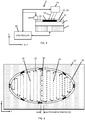
- FIG. 1 is a schematic diagram of a three-dimensional printing system 2 for fabricating a three-dimensional article 4.
- mutually orthogonal axes X, Y, and Z can be used.
- Axes X and Y are lateral axes and generally horizontal.
- mutually orthogonal lateral axes S and T can be used.
- Axis S is used to describe a variable direction along a boundary such as a seam.
- the axis T is transverse to S.
- Axis Z is a vertical axis that is generally aligned with a gravitational reference.
- a measure such as a quantity, a dimensional comparison, or an orientation comparison is by design and within manufacturing tolerances but as such may not be exact.
- System 2 includes a build module 6 having a motorized platform 8.
- the motorized platform 8 has a support surface 10 upon which the three-dimensional article 4 is formed.
- the motorized platform 8 is configured to vertically position an upper surface 12 (either an upper surface of article 4 or surface 10) at an optimal height to allow a powder dispenser 14 to dispense a layer of powder 15 onto the upper surface 12.
- the motorized platform 8 will be lowered before or after a layer of powder 15 is dispensed.
- the dispenser 14 dispenses layers of metal powder upon the motorized support 8.
- the layers can be any practical thickness but a typical layer thickness is less than about 200 microns or less than about 150 microns. More particularly, a layer thickness can be in a range of 10 to 100 microns. Yet more particularly, a layer thickness can be in a range of 20 to 50 microns.
- the metal powder can be a pure metal such as titanium or an alloy. Alloys can be based upon aluminum, nickel, titanium, cobalt, iron, copper, and other metals. Some metal powders can be powder mixtures of more than one pure metal, more than one alloy, or mixtures of alloys and pure metals. Yet other powders can include other materials such as ceramics.
- a fusing apparatus 16 is configured to form and scan a plurality of energy beams 18 over the upper surface 12 of dispensed powder 15 to selectively fuse the powder 15.
- An energy beam 18 can be a high powered optical beam, a particle beam, or an electron beam.
- a laser that outputs a beam having a power level of more than 100 watts is typical. Some lasers can output 500 watts, 1000 watts, or more than a kilowatt.
- the fusing apparatus 16 can include a laser, forming optics and scanning optics for forming and scanning the laser beam 18 over the surface 12.
- the plurality of energy beams 18 includes at least a first beam and a second beam.
- the plurality of energy beams can additionally include a third beam, or any number of beams.
- the plurality of energy beams 18 can individually be controlled and scanned independently and concurrently.
- the fusing apparatus 16 is configured to scan the energy beams over a laterally extending "build plane" 19 which is generally proximate to the upper surface 12 of the dispensed powder 15.
- the build plane 19 defines a lateral extent over which the plurality of energy beams 18 can address or operate upon.
- at least one of the energy beams 18 can address the entire build plane 19. In some embodiments, more than one energy beam 18 can individually address the entire build plane 19.
- the plurality of energy beams have a lateral alignment uncertainty. This can be defined for two beams. When attempting to address the same position on the build plane with the two beams (defined by their centroids), there is a lateral alignment uncertainty of one beam with respect to the other. This uncertainty can vary due to variability of motion of the scanning mechanism along with other mechanical tolerances.
- the alignment uncertainty can be quantified with a standard deviation.
- the lateral alignment error can be defined as equal to two or more standard deviations. In one implementation, the alignment uncertainty can be defined as equal to three standard deviations. In a more conservative implementation, the alignment error can be defined as equal to four standard deviations.
- the motorized platform 8, the powder dispenser 14, and the fusing apparatus 16 are all under control of a controller 20.
- the controller 20 includes a processor coupled to a computer-readable storage apparatus.
- the computer-readable storage apparatus includes a non-transitory or non-volatile storage medium that stores software instructions. When executed by the processor, the software instructions control various portions of system 2 including the motorized platform 8, the powder dispenser 14, and the fusing apparatus 16.
- the software instructions can also referred to as computer-readable code portions.
- the controller 20 can be an integrated module or it can include a plurality of computers that are electrically or wirelessly coupled to one another.
- the controller 20 includes a local controller that is physically integrated with other portions of system 2, a host computer, and a remote server. When the controller 20 is distributed among multiple computers, there can therefore be distributed processors and information storage devices that are accessed and utilized during the operation of the controller 20.
- the controller 20 is generally configured to perform the following operations: (1) position the motorized support with an upper surface 12 proximate to the build plane 19, (2) operate dispenser 14 to dispense a layer of powder, (3) operate the plurality of lasers 18 to selectively fuse portions of the dispensed layer of powder, and (4) repeat (1)-(3) to complete fabrication of the three-dimensional article 4.
- FIG. 2 illustrates an embodiment of a single layer of powder 15 that has been selectively fused.
- the selectively fused region includes a composite hatch pattern 22 surrounded by a contour 24.
- the composite hatch pattern 22 includes a first hatch pattern 26 and a second hatch pattern 28 joined by a seam 30.
- the first 26 and second 28 hatch patterns are individually formed by first and second lasers 18 respectively.
- the first 26 and second 28 hatch patterns are essentially contiguous at the seam 30.
- the hatch patterns 26 and 28 overlap based upon an alignment uncertainty of the first and second lasers in a direction transverse to the seam 30.
- the seam 30 extends along axis S and a transverse axis T is perpendicular to the seam 30.
- the seam 30 may be nonlinear.
- the direction S is defined as being tangential to the seam 30 and T is perpendicular to S.
- the first and second lasers have an alignment uncertainty with respect to each other along the transverse axis T.
- the first 26 and second 28 hatch patterns overlap along the transverse axis T with a transverse overlap distance (x).
- the transverse overlap distance (x) is at least equal to the alignment uncertainty.
- the transverse overlap distance (x) is at least two times the alignment uncertainty, three times the alignment uncertainty, or up to four times the alignment uncertainty.
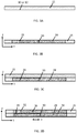
- FIGS. 3A-D are illustrations depicting a deposition and fusion sequence of powder layers having a seam 30 having a transverse location that varies from layer to layer.
- the motorized platform 8, powder dispenser 14, and fusing apparatus 16 are operated by controller 20 to perform these steps.
- dispenser 14 deposits a first layer of powder 15 on a surface 10 (or 12).
- first 26 and second 28 hatch patterns are fused by first and second energy beams 18 respectively. It is to be understood that the first 26 and second 28 hatch patterns overlap along the first seam 30 with a transverse overlap distance (x).
- the transverse overlap distance (x) along T is shown as a vertical line at seam 30 in FIG. 3B .
- dispenser 14 dispenses a second layer of powder 15 over the first selectively fused layer.
- third 32 and fourth 34 hatch patterns are fused by the first and second energy beams 18 respectively.
- the third 32 and fourth 34 hatch patterns overlap along second seam 36 with a transverse overlap distance (x). Seams 30 and 36 are offset from each other by a minimum distance u.
- Powder dispensing and fusing can continue in a manner similar to the illustrate of FIGS. 3A-D until there is a sequence 38 of selectively fused layers as illustrated in FIG. 4 .
- the layers are designated L1-L5 in order of formation.
- the seam 30 varies in lateral location from layer to layer along the transverse axis T. There is a minimum transverse lateral distance u between any two seams 30 within sequence 38.
- the seams 30 define a "seam zone" 40 having a width v which is the maximum transverse lateral distance between any two seams 30.
- the width v is at least two times u. In various embodiments, v is at least 3 times, at least four times, at least five times, or more than five times u.
- the seam locations along axis T can randomly vary from layer to layer with a limitation that any two layers in sequence have seams that are at least offset by some minimum transverse lateral distance u.
- an orientation of the seams can be rotated about the vertical axis Z from one sequence 38 to the next. This rotation can, in some embodiments, increase a strength of the article 4.
- the upper portion of the diagram represents hatch area 26 formed by the first energy beam 18.
- the lower portion of the diagram represents hatch area 28 formed by the second energy beam 18. Hatch areas are separated by seams 30 that are labeled at the right of the diagram for layers 1 to 5.
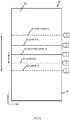
- FIG. 6 is a lateral diagram for FIG. 4 .
- the hatch areas 26 and 28 overlap across the seams 30.
- the overlap is related to a transverse alignment uncertainty along the axis T of the first beam 18 with respect to the second beam 18.
- the overlap along T at least equals the alignment uncertainty.
- the alignment uncertainty can be defined by three standard deviations of transverse alignment between the two beams.
- the value of u is at least equal to two times the transverse overlap distance (x). In some embodiments, the value of u can be three times x or more than three times x.
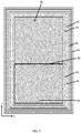
- FIG. 7 is a diagram of a selectively fused layer of powder.
- the concept of the seam 30 extends to contours.
- a first energy beam 18 defines an upper hatch area 26 and upper and inner contours 42.
- a second energy beam defines a lower hatch area 28 and lower and inner contours 44.
- the inner contours 42 and 44 overlap along the seam 30.
- the seam 30 may be discontinuous ⁇ that is, there may be a transverse offset between seams for the inner contours 42 and 44 and the hatch areas 26 and 28.
- outer contours 46 Surrounding the inner contours 42 and 44 are outer contours 46. Outer contours 46 are formed by a third energy beam 18. The number of inner and outer contours can be selected in part based upon an alignment uncertainty between the first and second energy beams.
Description
- The present disclosure concerns an apparatus and method for the fabrication of three dimensional (3D) articles utilizing powder materials. More particularly, the present disclosure concerns a manufacturing strategy that improves internal structural integrity of the articles when multiple energy beams are used.
- Three dimensional (3D) printing systems are in rapidly increasing use for purposes such as prototyping and manufacturing. One type of three dimensional printer utilizes a layer-by-layer process to form a three dimensional article of manufacture from powdered materials. Each layer of powdered material is selectively fused using an energy beam such as a laser, electron, or particle beam. Higher productivity printers can utilize multiple energy beams. One challenge with multiple energy beams is a transition from using one energy beam to another.
-
WO 2014/187606 A1 and itsfamily member EP 2 999 561 A1 disclose a method for forming a three-dimensional article through successive fusion of parts of a powder bed, which parts correspond to successive cross sections of the three-dimensional article, said method comprising the steps of: - providing a model of said three dimensional article;
- applying a first powder layer on a work table;
- directing a first energy beam from a first energy beam source over said work table, said directing of said first energy beam causing said first powder layer to fuse in first selected locations according to said model, so as to form a first part of the first cross section of said three-dimensional article; and directing a second energy beam from a second energy beam source over said work table, said directing of said second energy beam causing said first powder layer to fuse in second selected locations according to said model, so as to form a second part of the first cross section of said three-dimensional article,
- wherein said first and second locations of said first powder layer are at least partially overlapping each other in a first overlapping zone.
-
US 2017/0173737 A1 discloses a method of additive manufacturing for building a three-dimensional part in a part bed, the method comprising: - providing a first scanner having a first field of view;
- providing a second adjacent scanner having a second field of view wherein the first field of view and the second field of view at least partially overlap and
- wherein the first and second scanners are positioned at a selected height above the substrate;
- applying a layer of one or more materials onto or over the part bed;
- providing a plurality of laser sources configured to produce a plurality of laser beams;
- directing a first laser beam of the plurality of laser beams to the first scanner and a second laser beam of the plurality of laser beams to the second scanner;
- directing a movement of the laser beam from each corresponding scanner to selectively fuse the materials based on a sliced layer of a digital model for the three-dimensional part to produce a layer of the three-dimensional part by selectively directing laser energy to the materials in a selected pattern; and synchronizing the movement of the laser beams to continuously process the selected pattern in each layer of the three-dimensional part.
-
CN 108016034 A discloses a photo-curable laser scanning system comprising a powder bed; a plurality of laser modules, each laser module generates a laser beam, the laser beam is used to cure the powder material located on the powder bed, and each laser beam has a corresponding scanning area in each powder layer;
a laser scanner which is used to separately guide each laser beam to cure a corresponding scanning area along a straight scanning path wherein different laser beams form an overlapping area between adjacent scanning areas and wherein the same powder layer, the laser beam generated by the same laser module has at least two scanning paths of different lengths, and/or in adjacent powder layers, the length of at least one up and down corresponding scanning path is different. -
-
FIG. 1 is a schematic diagram of a three-dimensional printing system for fabricating a three-dimensional article. -
FIG. 2 is a diagram illustrating a single layer of powder that has been selectively fused. -
FIG. 3A is an illustration of a first layer of powder dispensed by a powder dispenser. -
FIG. 3B is an illustration of a first layer of powder that has been selectively fused by two different energy beams. -
FIG. 3C is an illustration of a second layer of powder that has been dispensed over a selectively fused first layer. -
FIG. 3D is an illustration of a two layers of powder that have been selectively fused by two different energy beams. -
FIG. 4 is an illustration of a sequence of powder layers that have been selectively fused. The layers have been individually fused with a first energy beam fusing a first area, a second energy beam fusing a second area, and a seam along which the first and second areas overlap. The seams are laterally offset from layer to layer with a minimum offset distance u and a lateral span of v. In the illustrated embodiment, there are five layers in a sequence. -
FIG. 5 is an illustration of a sequence of powder layers that have been selectively fused. The layers have been individually fused with a first energy beam fusing a first area, a second energy beam fusing a second area, and a seam along which the first and second areas overlap. The seams are laterally offset from layer to layer with a minimum offset distance u and a lateral span of v. In the illustrated embodiment, there are two sequences of five layers each. -
FIG. 6 is a diagram illustrating a lateral overlay view of a sequence of five fused layers. -
FIG. 7 is a diagram of a selectively fused layer of powder in which two different energy beams are used to form inner contours. - The embodiments of the invention are reflected in the independent claims. Preferred embodiments are reflected in the dependent claims.
- In a first aspect of the invention, a system for fabricating a three-dimensional article includes a powder dispenser and a fusing apparatus. The fusing apparatus is configured to generate and scan a plurality of beams across a build plane including a first beam and a second beam. The controller is configured to operate the powder dispenser and the fusing apparatus to form a sequence of r selectively fused layers of powder in which r is at least 3. The layers individually include a composite hatch area, the composite hatch area includes a first hatch area defined by the first energy beam and a second hatch area defined by the second energy beam. The first and second hatch areas overlap along a seam with a transverse overlap distance (x). A lateral location of the seam varies layer by layer. For the sequence of r layers the seam varies in lateral location over a zone having a lateral width of v and in which no two layers in the sequence have a transverse distance between seams of less than u. The distance u is at least equal to two times the transverse overlap distance (x). The distance u can be at least equal to three times the transverse overlap distance (x). The distance v equals at least two times u.
- In one implementation the plurality of beams includes a third beam. The controller is configured to operate the third beam to define at least part of a contour around the composite hatch area.
- In another implementation the plurality of beams includes a third beam. The plurality of beams define a plurality of contours around the composite hatch area including an outer contour and an inner contour. The outer contour is formed by the third beam and the inner contour is formed by a combination of the first beam and the second beam. The outer contour can include a plurality of offset contours. The inner contour can include a plurality of offset contours.
- In accordance with the present invention the transverse overlap distance (x) is based upon an alignment uncertainty of the first beam with respect to the second beam along a transverse axis that is transverse to the seam. The transverse overlap distance (x) is at least equal to the alignment uncertainty. The transverse overlap distance (x) can be at least equal to twice the alignment uncertainty, at least equal to three times the alignment uncertainty, or up to four times the alignment uncertainty.
- In further implementations, r is at least 4, at least 5, or greater than 5. The transverse seam location can be varied randomly from layer to layer.
- In a yet further implementation, the powder is a metal powder. The layers can be any practical thickness but a typical layer thickness is less than about 200 microns or less than about 150 microns. More particularly, a layer thickness can be in a range of 10 to 100 microns. Yet more particularly, a layer thickness can be in a range of 20 to 50 microns. The metal powder can be a pure metal such as titanium or an alloy. Alloys can be based upon aluminum, nickel, titanium, cobalt, iron, copper, and other metals. Some metal powders can be powder mixtures.
- In another embodiment, v is at least three times u. In other embodiments, v is at least four times u, or at least five times u.
- In a second aspect of the invention, a method for fabricating a three-dimensional article includes the following steps: (A) operating a powder dispenser to dispense a first layer of powder; (B) concurrently operating a plurality of energy beams including a first beam and a second beam to selectively fuse the layer of powder including (B1) operating the first beam to fuse a first hatch area and (B2) operating the second beam to fuse a second hatch area; the first and second hatch areas overlap along a first seam with a transverse overlap distance (x), wherein the transverse overlap distance (x) is based upon an alignment uncertainty of the first beam with respect to the second beam along a transverse axis that is transverse to the seam, and wherein the transverse overlap distance (x) is at least equal to the alignment uncertainty. (C) operating the powder dispenser to dispense a second layer of powder over the first layer of powder; (D) concurrently operating the plurality of energy beams to selectively fuse the second layer of powder including (D1) operating the first beam to fuse a third hatch area and (D2) operating the second beam to fuse a fourth hatch area; the third and fourth hatch areas overlap along a second seam; the second seam having an average transverse offset from the first seam by at least a value of u; (E) operating the powder dispenser to dispense a third layer of powder over the second layer of powder; (F) concurrently operating the plurality of energy beams to selectively fuse the third layer of powder including (F1) operating the first beam to fuse a fifth hatch area and operating the second beam to fuse a sixth hatch area; the fifth and sixth hatch areas overlap along a third seam; the third seam having an average transverse offset from the first seam and the second seam by at least a value of u; u is at least equal to two times the transverse overlap distance (x).
-
FIG. 1 is a schematic diagram of a three-dimensional printing system 2 for fabricating a three-dimensional article 4. In describingsystem 2, mutually orthogonal axes X, Y, and Z can be used. Axes X and Y are lateral axes and generally horizontal. Additionally, mutually orthogonal lateral axes S and T can be used. Axis S is used to describe a variable direction along a boundary such as a seam. The axis T is transverse to S. Axis Z is a vertical axis that is generally aligned with a gravitational reference. By "generally" we mean that a measure such as a quantity, a dimensional comparison, or an orientation comparison is by design and within manufacturing tolerances but as such may not be exact. -
System 2 includes abuild module 6 having amotorized platform 8. Themotorized platform 8 has asupport surface 10 upon which the three-dimensional article 4 is formed. Themotorized platform 8 is configured to vertically position an upper surface 12 (either an upper surface ofarticle 4 or surface 10) at an optimal height to allow apowder dispenser 14 to dispense a layer ofpowder 15 onto theupper surface 12. In an illustrative embodiment, themotorized platform 8 will be lowered before or after a layer ofpowder 15 is dispensed. - In an illustrative embodiment, the
dispenser 14 dispenses layers of metal powder upon themotorized support 8. The layers can be any practical thickness but a typical layer thickness is less than about 200 microns or less than about 150 microns. More particularly, a layer thickness can be in a range of 10 to 100 microns. Yet more particularly, a layer thickness can be in a range of 20 to 50 microns. The metal powder can be a pure metal such as titanium or an alloy. Alloys can be based upon aluminum, nickel, titanium, cobalt, iron, copper, and other metals. Some metal powders can be powder mixtures of more than one pure metal, more than one alloy, or mixtures of alloys and pure metals. Yet other powders can include other materials such as ceramics. - A fusing
apparatus 16 is configured to form and scan a plurality ofenergy beams 18 over theupper surface 12 of dispensedpowder 15 to selectively fuse thepowder 15. Anenergy beam 18 can be a high powered optical beam, a particle beam, or an electron beam. For a fusion of metal powder, a laser that outputs a beam having a power level of more than 100 watts is typical. Some lasers can output 500 watts, 1000 watts, or more than a kilowatt. The fusingapparatus 16 can include a laser, forming optics and scanning optics for forming and scanning thelaser beam 18 over thesurface 12. - In an embodiment, the plurality of
energy beams 18 includes at least a first beam and a second beam. The plurality of energy beams can additionally include a third beam, or any number of beams. The plurality ofenergy beams 18 can individually be controlled and scanned independently and concurrently. The fusingapparatus 16 is configured to scan the energy beams over a laterally extending "build plane" 19 which is generally proximate to theupper surface 12 of the dispensedpowder 15. The build plane 19 defines a lateral extent over which the plurality ofenergy beams 18 can address or operate upon. In a preferred embodiment, at least one of the energy beams 18 can address the entire build plane 19. In some embodiments, more than oneenergy beam 18 can individually address the entire build plane 19. - The plurality of energy beams have a lateral alignment uncertainty. This can be defined for two beams. When attempting to address the same position on the build plane with the two beams (defined by their centroids), there is a lateral alignment uncertainty of one beam with respect to the other. This uncertainty can vary due to variability of motion of the scanning mechanism along with other mechanical tolerances. The alignment uncertainty can be quantified with a standard deviation. The lateral alignment error can be defined as equal to two or more standard deviations. In one implementation, the alignment uncertainty can be defined as equal to three standard deviations. In a more conservative implementation, the alignment error can be defined as equal to four standard deviations.
- The
motorized platform 8, thepowder dispenser 14, and the fusingapparatus 16 are all under control of acontroller 20. Thecontroller 20 includes a processor coupled to a computer-readable storage apparatus. The computer-readable storage apparatus includes a non-transitory or non-volatile storage medium that stores software instructions. When executed by the processor, the software instructions control various portions ofsystem 2 including themotorized platform 8, thepowder dispenser 14, and the fusingapparatus 16. The software instructions can also referred to as computer-readable code portions. - The
controller 20 can be an integrated module or it can include a plurality of computers that are electrically or wirelessly coupled to one another. In a particular embodiment, thecontroller 20 includes a local controller that is physically integrated with other portions ofsystem 2, a host computer, and a remote server. When thecontroller 20 is distributed among multiple computers, there can therefore be distributed processors and information storage devices that are accessed and utilized during the operation of thecontroller 20. - The
controller 20 is generally configured to perform the following operations: (1) position the motorized support with anupper surface 12 proximate to the build plane 19, (2) operatedispenser 14 to dispense a layer of powder, (3) operate the plurality oflasers 18 to selectively fuse portions of the dispensed layer of powder, and (4) repeat (1)-(3) to complete fabrication of the three-dimensional article 4. -
FIG. 2 illustrates an embodiment of a single layer ofpowder 15 that has been selectively fused. The selectively fused region includes acomposite hatch pattern 22 surrounded by acontour 24. Thecomposite hatch pattern 22 includes afirst hatch pattern 26 and asecond hatch pattern 28 joined by aseam 30. The first 26 and second 28 hatch patterns are individually formed by first andsecond lasers 18 respectively. The first 26 and second 28 hatch patterns are essentially contiguous at theseam 30. Thehatch patterns seam 30. In the illustration, theseam 30 extends along axis S and a transverse axis T is perpendicular to theseam 30. For some geometries, theseam 30 may be nonlinear. Then, the direction S is defined as being tangential to theseam 30 and T is perpendicular to S. - In a typical embodiment, the first and second lasers have an alignment uncertainty with respect to each other along the transverse axis T. The first 26 and second 28 hatch patterns overlap along the transverse axis T with a transverse overlap distance (x). The transverse overlap distance (x) is at least equal to the alignment uncertainty. Preferably the transverse overlap distance (x) is at least two times the alignment uncertainty, three times the alignment uncertainty, or up to four times the alignment uncertainty.
-
FIGS. 3A-D are illustrations depicting a deposition and fusion sequence of powder layers having aseam 30 having a transverse location that varies from layer to layer. Themotorized platform 8,powder dispenser 14, and fusingapparatus 16 are operated bycontroller 20 to perform these steps. - According to
FIG. 3A ,dispenser 14 deposits a first layer ofpowder 15 on a surface 10 (or 12). According toFIG. 3B , first 26 and second 28 hatch patterns are fused by first andsecond energy beams 18 respectively. It is to be understood that the first 26 and second 28 hatch patterns overlap along thefirst seam 30 with a transverse overlap distance (x). The transverse overlap distance (x) along T is shown as a vertical line atseam 30 inFIG. 3B . - According to
FIG. 3C ,dispenser 14 dispenses a second layer ofpowder 15 over the first selectively fused layer. According toFIG. 3D , third 32 and fourth 34 hatch patterns are fused by the first andsecond energy beams 18 respectively. The third 32 and fourth 34 hatch patterns overlap alongsecond seam 36 with a transverse overlap distance (x).Seams - Powder dispensing and fusing can continue in a manner similar to the illustrate of
FIGS. 3A-D until there is asequence 38 of selectively fused layers as illustrated inFIG. 4 . This is a sequence of five layers. The variable r will be defined as a number of layers in a sequence. ForFIG. 4 , r = 5. The layers are designated L1-L5 in order of formation. - The
seam 30 varies in lateral location from layer to layer along the transverse axis T. There is a minimum transverse lateral distance u between any twoseams 30 withinsequence 38. Theseams 30 define a "seam zone" 40 having a width v which is the maximum transverse lateral distance between any twoseams 30. - The width v is at least two times u. In various embodiments, v is at least 3 times, at least four times, at least five times, or more than five times u.
-
FIG. 5 depicts thesequence 38 for r = 5 repeated twice. Thesequence 30 can be repeated any number of times. More generally, sequences can have r values of three or more. Sequences for r = 4, r = 5, r > 5, r > 10 are possible. Also, thesequences 38 do not have to be exactly the same. For example, there could be a sequence with r = 5 above a sequence for which r = 10. In some embodiments, the seam locations along axis T can randomly vary from layer to layer with a limitation that any two layers in sequence have seams that are at least offset by some minimum transverse lateral distance u. - In some embodiments, an orientation of the seams can be rotated about the vertical axis Z from one
sequence 38 to the next. This rotation can, in some embodiments, increase a strength of thearticle 4. -
FIG. 6 is a diagram illustrating lateral overlay view of asequence 38 of five fused layers (r = 5). The upper portion of the diagram representshatch area 26 formed by thefirst energy beam 18. The lower portion of the diagram representshatch area 28 formed by thesecond energy beam 18. Hatch areas are separated byseams 30 that are labeled at the right of the diagram forlayers 1 to 5. Thus,FIG. 6 is a lateral diagram forFIG. 4 . - In typical embodiments, the
hatch areas seams 30. The overlap is related to a transverse alignment uncertainty along the axis T of thefirst beam 18 with respect to thesecond beam 18. According to the invention, the overlap along T at least equals the alignment uncertainty. The alignment uncertainty can be defined by three standard deviations of transverse alignment between the two beams. - The value of u is at least equal to two times the transverse overlap distance (x). In some embodiments, the value of u can be three times x or more than three times x.
-
FIG. 7 is a diagram of a selectively fused layer of powder. In this example, the concept of theseam 30 extends to contours. In the illustrated embodiment, afirst energy beam 18 defines anupper hatch area 26 and upper andinner contours 42. A second energy beam defines alower hatch area 28 and lower andinner contours 44. Theinner contours seam 30. In some embodiments, theseam 30 may be discontinuous ― that is, there may be a transverse offset between seams for theinner contours hatch areas - Surrounding the
inner contours outer contours 46.Outer contours 46 are formed by athird energy beam 18. The number of inner and outer contours can be selected in part based upon an alignment uncertainty between the first and second energy beams.
Claims (11)
- A system for fabricating a three-dimensional article (4) comprising:a powder dispenser (14) for sequentially dispensing individual layers of powder (15);a fusing apparatus (16) for generating and scanning a plurality of energy beams including a first beam and a second beam to selectively melt the layers of powder (15); anda controller (20) configured to:
operate the powder dispenser (14) and the fusing apparatus (16) to form a sequence of r selectively fused layers of powder in which r is at least 3, the layers individually including a composite hatch area, the composite hatch area includes a first hatch area (26) defined by the first energy beam and a second hatch area (28) defined by the second energy beam, the first and second hatch areas overlap along a seam (30) with a transverse overlap distance (x), a lateral location of the seam (30) varying by layer, for the sequence of r layers the seam (30) varies in lateral location over a zone having a lateral width of v and in which no two layers in the sequence (38) have a transverse distance between seams (30) of less than u in which u is at least equal to two times the transverse overlap distance (x), characterized in that the transverse overlap distance (x) is based upon an alignment uncertainty of the first beam with respect to the second beam along a transverse axis that is transverse to the seam (30), and wherein the transverse overlap distance (x) is at least equal to the alignment uncertainty. - The system according to claim 1 wherein the plurality of beams include a third beam (18), the controller (20) is configured to operate the third beam (18) to define at least part of a contour around the composite hatch area.
- The system according to claim 2 wherein the plurality of beams define a plurality of contours around the composite hatch area including an outer contour (46) and an inner contour (42, 44), the outer contour (46) is formed by the third beam (18) and the inner contour (42, 44) is formed by a combination of the first beam and the second beam.
- The system according to any one of claims 1 to 3 wherein r is at least 5.
- The system according to any one of claims 1 to 4 wherein the powder dispenser (14) contains metal powder.
- A method for fabricating a three-dimensional article (4) comprising:operating a powder dispenser (14) to dispense a first layer of powder;concurrently operating a plurality of energy beams including a first beam and a second beam to selectively fuse the layer of powder including:operating the first beam to fuse a first hatch area (26); andoperating the second beam to fuse a second hatch area (28), the first and second hatch areas overlap along a first seam (30) with a transverse overlap distance (x);operating the powder dispenser (14) to dispense a second layer of powder over the first layer of powder;concurrently operating the plurality of energy beams to selectively fuse the second layer of powder including:operating the first beam to fuse a third hatch area (32); andoperating the second beam to fuse a fourth hatch area (34), the third and fourth hatch areas overlap along a second seam (36), the second seam (36) having an average transverse offset from the first seam by at least a value of u;operating the powder dispenser (14) to dispense a third layer of powder over the second layer of powder;concurrently operating the plurality of energy beams to selectively fuse the third layer of powdering including:operating the first beam to fuse a fifth hatch area; andoperating the second beam to fuse a sixth hatch area, the fifth and sixth hatch areas overlap along a third seam, the third seam having an average transverse offset from the first seam and the second seam by at least a value of u, u is at least equal to two times the transverse overlap distance (x), characterized in that the transverse overlap distance (x) is based upon an alignment uncertainty of the first beam with respect to the second beam, and wherein the transverse overlap distance (x) is at least equal to the alignment uncertainty.
- The method according to claim 6 further comprising operating a third beam to fuse a contour around the first and second hatch areas.
- The method according to claim 7 further comprising operating the first and second beams to define at least one inner contour (42, 44) around the first and second hatch areas and operating the third beam to define an outer contour (46) around the inner contour (42, 44).
- A computer-readable storage apparatus for fabricating a three-dimensional article (4), the computer-readable storage apparatus including a non-transitory storage medium storing software instructions, in response to execution by a processor the software instructions cause a system according to any of claims 1 to 5 to:operate a powder dispenser (14) to dispense a first layer of powder;operate a plurality of energy beams including a first beam and a second beam to selectively fuse the layer of powder including:operate the first beam to fuse a first hatch area (26); andoperate the second beam to fuse a second hatch area (28), the first and second hatch areas overlap along a first seam (30) with a transverse overlap distance (x);operate the powder dispenser (14) to dispense a second layer of powder over the first layer of powder;concurrently operate the plurality of energy beams to selectively fuse the second layer of powder including:operate the first beam to fuse a third hatch area (32); andoperate the second beam to fuse a fourth hatch area (34), the third and fourth hatch areas overlap along a second seam (36), the second seam (36) having an average transverse offset from the first seam (30) by at least a value of u;operate the powder dispenser to dispense a third layer of powder over the second layer of powder;concurrently operate the plurality of energy beams to selectively fuse the third layer of powdering including:operate the first beam to fuse a fifth hatch area; andoperate the second beam to fuse a sixth hatch area, the fifth and sixth hatch areas overlap along a third seam, the third seam having an average transverse offset from the first seam and the second seam by at least a value of u, u is at least equal to two times the transverse overlap distance (x), characterized in that the transverse overlap distance (x) is based upon an alignment uncertainty of the first beam with respect to the second beam, wherein the transverse overlap distance (x) is at least is equal to the alignment uncertainty.
- The computer-readable storage apparatus according to claim 9 wherein response to execution by a processor the software instructions cause a system to operate a third beam to fuse a contour around the first and second hatch areas.
- The computer-readable storage apparatus according to claim 10 wherein response to execution by a processor the software instructions cause a system to operate the first and second beams to define at least one inner contour (42, 44) around the first and second hatch areas and operate the third beam to define an outer contour (46) around the inner contour (42, 44).
Applications Claiming Priority (1)
| Application Number | Priority Date | Filing Date | Title |
|---|---|---|---|
| EP19167790.5A EP3722075B1 (en) | 2019-04-08 | 2019-04-08 | Three-dimensional printing system optimizing seams between zones for multiple energy beams |
Publications (2)
| Publication Number | Publication Date |
|---|---|
| EP3722076A1 EP3722076A1 (en) | 2020-10-14 |
| EP3722076B1 true EP3722076B1 (en) | 2021-11-10 |
Family
ID=66102479
Family Applications (2)
| Application Number | Title | Priority Date | Filing Date |
|---|---|---|---|
| EP19167790.5A Active EP3722075B1 (en) | 2019-04-08 | 2019-04-08 | Three-dimensional printing system optimizing seams between zones for multiple energy beams |
| EP20163823.6A Active EP3722076B1 (en) | 2019-04-08 | 2020-03-18 | Three-dimensional printing system and method optimizing seams between zones for multiple energy beams |
Family Applications Before (1)
| Application Number | Title | Priority Date | Filing Date |
|---|---|---|---|
| EP19167790.5A Active EP3722075B1 (en) | 2019-04-08 | 2019-04-08 | Three-dimensional printing system optimizing seams between zones for multiple energy beams |
Country Status (3)
| Country | Link |
|---|---|
| US (1) | US20200316717A1 (en) |
| EP (2) | EP3722075B1 (en) |
| JP (1) | JP2020172104A (en) |
Families Citing this family (5)
| Publication number | Priority date | Publication date | Assignee | Title |
|---|---|---|---|---|
| JP2022063720A (en) | 2020-10-12 | 2022-04-22 | 日本電気株式会社 | Image correction device |
| JPWO2022114210A1 (en) * | 2020-11-30 | 2022-06-02 | ||
| US11766825B2 (en) | 2021-10-14 | 2023-09-26 | 3D Systems, Inc. | Three-dimensional printing system with improved powder coating uniformity |
| KR102595164B1 (en) | 2021-11-17 | 2023-10-31 | 한국생산기술연구원 | Optimized scan interval derivation apparatus and method for high speed high density additive molding |
| WO2023168209A1 (en) * | 2022-03-04 | 2023-09-07 | Layerwise Nv | Three-dimensional (3d) printing system with improved layer-to-layer contour generation to improve surface quality |
Citations (1)
| Publication number | Priority date | Publication date | Assignee | Title |
|---|---|---|---|---|
| EP2999561B1 (en) * | 2013-05-23 | 2017-02-22 | Arcam Ab | Method for additive manufacturing |
Family Cites Families (6)
| Publication number | Priority date | Publication date | Assignee | Title |
|---|---|---|---|---|
| CN105492188B (en) * | 2013-06-10 | 2018-09-11 | 瑞尼斯豪公司 | Selective laser curing apparatus and method |
| US10583529B2 (en) * | 2015-12-17 | 2020-03-10 | Eos Of North America, Inc. | Additive manufacturing method using a plurality of synchronized laser beams |
| JP6132962B1 (en) * | 2016-06-01 | 2017-05-24 | 株式会社ソディック | Laminate modeling apparatus and method of reusing material powder of additive modeling apparatus |
| EP3338916A1 (en) * | 2016-12-22 | 2018-06-27 | HILTI Aktiengesellschaft | Method for layerwise manufacturing of a component made of powdery material |
| JP6862193B2 (en) * | 2017-01-25 | 2021-04-21 | キヤノン株式会社 | Manufacturing method of 3D modeled object, and 3D modeling device |
| CN108016034B (en) * | 2017-12-15 | 2020-10-02 | 苏州中瑞智创三维科技股份有限公司 | Photocuring laser scanning system and method |
-
2019
- 2019-04-08 EP EP19167790.5A patent/EP3722075B1/en active Active
-
2020
- 2020-03-18 EP EP20163823.6A patent/EP3722076B1/en active Active
- 2020-03-26 JP JP2020055950A patent/JP2020172104A/en active Pending
- 2020-03-26 US US16/830,971 patent/US20200316717A1/en active Pending
Patent Citations (1)
| Publication number | Priority date | Publication date | Assignee | Title |
|---|---|---|---|---|
| EP2999561B1 (en) * | 2013-05-23 | 2017-02-22 | Arcam Ab | Method for additive manufacturing |
Also Published As
| Publication number | Publication date |
|---|---|
| US20200316717A1 (en) | 2020-10-08 |
| EP3722075B1 (en) | 2022-06-29 |
| EP3722076A1 (en) | 2020-10-14 |
| EP3722075A1 (en) | 2020-10-14 |
| JP2020172104A (en) | 2020-10-22 |
Similar Documents
| Publication | Publication Date | Title |
|---|---|---|
| EP3722076B1 (en) | Three-dimensional printing system and method optimizing seams between zones for multiple energy beams | |
| JP7085840B2 (en) | Multiple beam additional manufacturing | |
| US6861613B1 (en) | Device and method for the preparation of building components from a combination of materials | |
| US11090866B2 (en) | Apparatus and method for manufacturing stereoscopic shape using laser and powder | |
| CN111417486B (en) | Method for designing layered structure, method for manufacturing layered structure, manufacturing apparatus, and recording medium | |
| US11084097B2 (en) | Additive manufacturing with cell processing recipes | |
| KR20200094765A (en) | Additive manufacturing using overlapping light beams | |
| US20180186073A1 (en) | Additive manufacturing systems including a particulate dispenser and methods of operating such systems | |
| US11731348B2 (en) | Three dimensional printing system with improved surface properties | |
| US11679564B2 (en) | Three-dimensional printing system optimizing contour formation for multiple energy beams | |
| JP7341232B2 (en) | Vertically offset melting sequences for three-dimensional printing systems | |
| US20220203453A1 (en) | Branching Support for Metals That Minimizes Material Usage | |
| JP2022506643A (en) | Alternating double-layer contouring and hatching for 3D manufacturing | |
| US20230278106A1 (en) | Three-Dimensional (3D) Printing System with Improved Layer-to-Layer Contour Generation to Improve Surface Quality | |
| CN111132838A (en) | 3D printing method and device | |
| JP7405223B2 (en) | Processing system and processing method | |
| KR20230060082A (en) | Deposition ring |
Legal Events
| Date | Code | Title | Description |
|---|---|---|---|
| PUAI | Public reference made under article 153(3) epc to a published international application that has entered the european phase |
Free format text: ORIGINAL CODE: 0009012 |
|
| STAA | Information on the status of an ep patent application or granted ep patent |
Free format text: STATUS: THE APPLICATION HAS BEEN PUBLISHED |
|
| AK | Designated contracting states |
Kind code of ref document: A1 Designated state(s): AL AT BE BG CH CY CZ DE DK EE ES FI FR GB GR HR HU IE IS IT LI LT LU LV MC MK MT NL NO PL PT RO RS SE SI SK SM TR |
|
| AX | Request for extension of the european patent |
Extension state: BA ME |
|
| STAA | Information on the status of an ep patent application or granted ep patent |
Free format text: STATUS: REQUEST FOR EXAMINATION WAS MADE |
|
| 17P | Request for examination filed |
Effective date: 20210223 |
|
| RBV | Designated contracting states (corrected) |
Designated state(s): AL AT BE BG CH CY CZ DE DK EE ES FI FR GB GR HR HU IE IS IT LI LT LU LV MC MK MT NL NO PL PT RO RS SE SI SK SM TR |
|
| RIC1 | Information provided on ipc code assigned before grant |
Ipc: B29C 64/153 20170101AFI20210608BHEP Ipc: B22F 3/105 20060101ALI20210608BHEP Ipc: B29C 64/268 20170101ALI20210608BHEP Ipc: B29C 64/277 20170101ALI20210608BHEP Ipc: B33Y 10/00 20150101ALI20210608BHEP Ipc: B33Y 30/00 20150101ALI20210608BHEP Ipc: B22F 10/20 20210101ALI20210608BHEP Ipc: B22F 12/00 20210101ALI20210608BHEP |
|
| GRAP | Despatch of communication of intention to grant a patent |
Free format text: ORIGINAL CODE: EPIDOSNIGR1 |
|
| STAA | Information on the status of an ep patent application or granted ep patent |
Free format text: STATUS: GRANT OF PATENT IS INTENDED |
|
| INTG | Intention to grant announced |
Effective date: 20210726 |
|
| GRAS | Grant fee paid |
Free format text: ORIGINAL CODE: EPIDOSNIGR3 |
|
| GRAA | (expected) grant |
Free format text: ORIGINAL CODE: 0009210 |
|
| STAA | Information on the status of an ep patent application or granted ep patent |
Free format text: STATUS: THE PATENT HAS BEEN GRANTED |
|
| AK | Designated contracting states |
Kind code of ref document: B1 Designated state(s): AL AT BE BG CH CY CZ DE DK EE ES FI FR GB GR HR HU IE IS IT LI LT LU LV MC MK MT NL NO PL PT RO RS SE SI SK SM TR |
|
| REG | Reference to a national code |
Ref country code: GB Ref legal event code: FG4D |
|
| REG | Reference to a national code |
Ref country code: AT Ref legal event code: REF Ref document number: 1445676 Country of ref document: AT Kind code of ref document: T Effective date: 20211115 Ref country code: CH Ref legal event code: EP |
|
| REG | Reference to a national code |
Ref country code: DE Ref legal event code: R096 Ref document number: 602020000945 Country of ref document: DE |
|
| REG | Reference to a national code |
Ref country code: IE Ref legal event code: FG4D |
|
| REG | Reference to a national code |
Ref country code: LT Ref legal event code: MG9D |
|
| REG | Reference to a national code |
Ref country code: NL Ref legal event code: MP Effective date: 20211110 |
|
| REG | Reference to a national code |
Ref country code: AT Ref legal event code: MK05 Ref document number: 1445676 Country of ref document: AT Kind code of ref document: T Effective date: 20211110 |
|
| PG25 | Lapsed in a contracting state [announced via postgrant information from national office to epo] |
Ref country code: RS Free format text: LAPSE BECAUSE OF FAILURE TO SUBMIT A TRANSLATION OF THE DESCRIPTION OR TO PAY THE FEE WITHIN THE PRESCRIBED TIME-LIMIT Effective date: 20211110 Ref country code: LT Free format text: LAPSE BECAUSE OF FAILURE TO SUBMIT A TRANSLATION OF THE DESCRIPTION OR TO PAY THE FEE WITHIN THE PRESCRIBED TIME-LIMIT Effective date: 20211110 Ref country code: FI Free format text: LAPSE BECAUSE OF FAILURE TO SUBMIT A TRANSLATION OF THE DESCRIPTION OR TO PAY THE FEE WITHIN THE PRESCRIBED TIME-LIMIT Effective date: 20211110 Ref country code: BG Free format text: LAPSE BECAUSE OF FAILURE TO SUBMIT A TRANSLATION OF THE DESCRIPTION OR TO PAY THE FEE WITHIN THE PRESCRIBED TIME-LIMIT Effective date: 20220210 Ref country code: AT Free format text: LAPSE BECAUSE OF FAILURE TO SUBMIT A TRANSLATION OF THE DESCRIPTION OR TO PAY THE FEE WITHIN THE PRESCRIBED TIME-LIMIT Effective date: 20211110 |
|
| PG25 | Lapsed in a contracting state [announced via postgrant information from national office to epo] |
Ref country code: IS Free format text: LAPSE BECAUSE OF FAILURE TO SUBMIT A TRANSLATION OF THE DESCRIPTION OR TO PAY THE FEE WITHIN THE PRESCRIBED TIME-LIMIT Effective date: 20220310 Ref country code: SE Free format text: LAPSE BECAUSE OF FAILURE TO SUBMIT A TRANSLATION OF THE DESCRIPTION OR TO PAY THE FEE WITHIN THE PRESCRIBED TIME-LIMIT Effective date: 20211110 Ref country code: PT Free format text: LAPSE BECAUSE OF FAILURE TO SUBMIT A TRANSLATION OF THE DESCRIPTION OR TO PAY THE FEE WITHIN THE PRESCRIBED TIME-LIMIT Effective date: 20220310 Ref country code: PL Free format text: LAPSE BECAUSE OF FAILURE TO SUBMIT A TRANSLATION OF THE DESCRIPTION OR TO PAY THE FEE WITHIN THE PRESCRIBED TIME-LIMIT Effective date: 20211110 Ref country code: NO Free format text: LAPSE BECAUSE OF FAILURE TO SUBMIT A TRANSLATION OF THE DESCRIPTION OR TO PAY THE FEE WITHIN THE PRESCRIBED TIME-LIMIT Effective date: 20220210 Ref country code: NL Free format text: LAPSE BECAUSE OF FAILURE TO SUBMIT A TRANSLATION OF THE DESCRIPTION OR TO PAY THE FEE WITHIN THE PRESCRIBED TIME-LIMIT Effective date: 20211110 Ref country code: LV Free format text: LAPSE BECAUSE OF FAILURE TO SUBMIT A TRANSLATION OF THE DESCRIPTION OR TO PAY THE FEE WITHIN THE PRESCRIBED TIME-LIMIT Effective date: 20211110 Ref country code: HR Free format text: LAPSE BECAUSE OF FAILURE TO SUBMIT A TRANSLATION OF THE DESCRIPTION OR TO PAY THE FEE WITHIN THE PRESCRIBED TIME-LIMIT Effective date: 20211110 Ref country code: GR Free format text: LAPSE BECAUSE OF FAILURE TO SUBMIT A TRANSLATION OF THE DESCRIPTION OR TO PAY THE FEE WITHIN THE PRESCRIBED TIME-LIMIT Effective date: 20220211 |
|
| PG25 | Lapsed in a contracting state [announced via postgrant information from national office to epo] |
Ref country code: SM Free format text: LAPSE BECAUSE OF FAILURE TO SUBMIT A TRANSLATION OF THE DESCRIPTION OR TO PAY THE FEE WITHIN THE PRESCRIBED TIME-LIMIT Effective date: 20211110 Ref country code: SK Free format text: LAPSE BECAUSE OF FAILURE TO SUBMIT A TRANSLATION OF THE DESCRIPTION OR TO PAY THE FEE WITHIN THE PRESCRIBED TIME-LIMIT Effective date: 20211110 Ref country code: RO Free format text: LAPSE BECAUSE OF FAILURE TO SUBMIT A TRANSLATION OF THE DESCRIPTION OR TO PAY THE FEE WITHIN THE PRESCRIBED TIME-LIMIT Effective date: 20211110 Ref country code: ES Free format text: LAPSE BECAUSE OF FAILURE TO SUBMIT A TRANSLATION OF THE DESCRIPTION OR TO PAY THE FEE WITHIN THE PRESCRIBED TIME-LIMIT Effective date: 20211110 Ref country code: EE Free format text: LAPSE BECAUSE OF FAILURE TO SUBMIT A TRANSLATION OF THE DESCRIPTION OR TO PAY THE FEE WITHIN THE PRESCRIBED TIME-LIMIT Effective date: 20211110 Ref country code: DK Free format text: LAPSE BECAUSE OF FAILURE TO SUBMIT A TRANSLATION OF THE DESCRIPTION OR TO PAY THE FEE WITHIN THE PRESCRIBED TIME-LIMIT Effective date: 20211110 Ref country code: CZ Free format text: LAPSE BECAUSE OF FAILURE TO SUBMIT A TRANSLATION OF THE DESCRIPTION OR TO PAY THE FEE WITHIN THE PRESCRIBED TIME-LIMIT Effective date: 20211110 |
|
| REG | Reference to a national code |
Ref country code: DE Ref legal event code: R097 Ref document number: 602020000945 Country of ref document: DE |
|
| PLBE | No opposition filed within time limit |
Free format text: ORIGINAL CODE: 0009261 |
|
| STAA | Information on the status of an ep patent application or granted ep patent |
Free format text: STATUS: NO OPPOSITION FILED WITHIN TIME LIMIT |
|
| 26N | No opposition filed |
Effective date: 20220811 |
|
| PG25 | Lapsed in a contracting state [announced via postgrant information from national office to epo] |
Ref country code: MC Free format text: LAPSE BECAUSE OF FAILURE TO SUBMIT A TRANSLATION OF THE DESCRIPTION OR TO PAY THE FEE WITHIN THE PRESCRIBED TIME-LIMIT Effective date: 20211110 Ref country code: AL Free format text: LAPSE BECAUSE OF FAILURE TO SUBMIT A TRANSLATION OF THE DESCRIPTION OR TO PAY THE FEE WITHIN THE PRESCRIBED TIME-LIMIT Effective date: 20211110 |
|
| PG25 | Lapsed in a contracting state [announced via postgrant information from national office to epo] |
Ref country code: SI Free format text: LAPSE BECAUSE OF FAILURE TO SUBMIT A TRANSLATION OF THE DESCRIPTION OR TO PAY THE FEE WITHIN THE PRESCRIBED TIME-LIMIT Effective date: 20211110 |
|
| REG | Reference to a national code |
Ref country code: BE Ref legal event code: MM Effective date: 20220331 |
|
| PG25 | Lapsed in a contracting state [announced via postgrant information from national office to epo] |
Ref country code: LU Free format text: LAPSE BECAUSE OF NON-PAYMENT OF DUE FEES Effective date: 20220318 Ref country code: IE Free format text: LAPSE BECAUSE OF NON-PAYMENT OF DUE FEES Effective date: 20220318 |
|
| PG25 | Lapsed in a contracting state [announced via postgrant information from national office to epo] |
Ref country code: BE Free format text: LAPSE BECAUSE OF NON-PAYMENT OF DUE FEES Effective date: 20220331 |
|
| PGFP | Annual fee paid to national office [announced via postgrant information from national office to epo] |
Ref country code: FR Payment date: 20230327 Year of fee payment: 4 |
|
| PGFP | Annual fee paid to national office [announced via postgrant information from national office to epo] |
Ref country code: DE Payment date: 20230329 Year of fee payment: 4 |
|
| P01 | Opt-out of the competence of the unified patent court (upc) registered |
Effective date: 20230427 |
|
| PGFP | Annual fee paid to national office [announced via postgrant information from national office to epo] |
Ref country code: IT Payment date: 20230331 Year of fee payment: 4 |
|
| REG | Reference to a national code |
Ref country code: CH Ref legal event code: PL |
|
| PG25 | Lapsed in a contracting state [announced via postgrant information from national office to epo] |
Ref country code: LI Free format text: LAPSE BECAUSE OF NON-PAYMENT OF DUE FEES Effective date: 20230331 Ref country code: CH Free format text: LAPSE BECAUSE OF NON-PAYMENT OF DUE FEES Effective date: 20230331 |