EP3721744B1 - Extractable assembly group for one wheel of a luggage - Google Patents
Extractable assembly group for one wheel of a luggage Download PDFInfo
- Publication number
- EP3721744B1 EP3721744B1 EP20163371.6A EP20163371A EP3721744B1 EP 3721744 B1 EP3721744 B1 EP 3721744B1 EP 20163371 A EP20163371 A EP 20163371A EP 3721744 B1 EP3721744 B1 EP 3721744B1
- Authority
- EP
- European Patent Office
- Prior art keywords
- slider
- bracket
- protrusion
- support
- pass
- Prior art date
- Legal status (The legal status is an assumption and is not a legal conclusion. Google has not performed a legal analysis and makes no representation as to the accuracy of the status listed.)
- Active
Links
Images





Classifications
-
- A—HUMAN NECESSITIES
- A45—HAND OR TRAVELLING ARTICLES
- A45C—PURSES; LUGGAGE; HAND CARRIED BAGS
- A45C5/00—Rigid or semi-rigid luggage
- A45C5/14—Rigid or semi-rigid luggage with built-in rolling means
- A45C5/143—Rigid or semi-rigid luggage with built-in rolling means detachable
-
- B—PERFORMING OPERATIONS; TRANSPORTING
- B60—VEHICLES IN GENERAL
- B60B—VEHICLE WHEELS; CASTORS; AXLES FOR WHEELS OR CASTORS; INCREASING WHEEL ADHESION
- B60B33/00—Castors in general ; Anti-clogging castors
- B60B33/0002—Castors in general ; Anti-clogging castors assembling to the object, e.g. furniture
- B60B33/0005—Castors in general ; Anti-clogging castors assembling to the object, e.g. furniture characterised by mounting method
- B60B33/001—Castors in general ; Anti-clogging castors assembling to the object, e.g. furniture characterised by mounting method by snapping, clicking or latching in
-
- B—PERFORMING OPERATIONS; TRANSPORTING
- B60—VEHICLES IN GENERAL
- B60B—VEHICLE WHEELS; CASTORS; AXLES FOR WHEELS OR CASTORS; INCREASING WHEEL ADHESION
- B60B2200/00—Type of product being used or applied
- B60B2200/40—Articles of daily use
- B60B2200/45—Suitcases
Definitions
- the present invention relates to an extractable assembly group for one wheel of a luggage.
- Luggages are known in the state of the art comprising two or more wheels mounted to the luggage by means of assembly groups.
- An assembly group comprises a bracket, which is fitted with a lower portion of a luggage.
- the bracket comprises means for rotatably mounting a fork for wheels.
- the fork rotatably mounts one or more wheels.
- Assembly groups for luggage wheels exist comprising screws for removably coupling the fork to the bracket so as to be able to assemble or disassemble the fork from the bracket.
- the fork mounts wheels for the luggage. The screws allow the bracket to be mounted to the fork in a fixed and safe manner.
- assembly groups for luggage wheels of the prior art allow the fork to be disassembled from the bracket with difficulty, using a screwdriver to unscrew the engagement means between the fork and the bracket.
- a user wishing to load the luggage into a boot of a car, taking up as little space as possible, should need a long time to unscrew screws to disassemble the fork from the bracket. It is not possible to disassemble the forks from the bracket in a safe, easy and quick manner
- CN104149547A discloses an extractable assembly group for at least one wheel of a luggage according to the preamble of claim 1.
- An object of the present invention consists of making an extractable assembly group for a wheel of a luggage, which allows the wheels to be replaced in an easier, quicker and safer manner, allowing the extractable assembly group for the wheel to be safer and preventing the fork for the wheel from dangerously unengaging from the bracket during use of the luggage.
- An extractable assembly group 100 for one wheel of a luggage is shown with reference to the above-mentioned figures.
- the assembly group 100 comprises a fork 10 adapted to rotatably mount at least one wheel about a first geometrical axis A, a support 20 for the rotation of said fork 10 adapted to rotatably mount said fork 10 about a substantially vertical geometrical axis V, which is perpendicular to said first geometrical axis A, a bracket 30 adapted to separably mount said support 20 for said fork 10, wherein the bracket 30 is mountable with the luggage.
- the bracket separably mounts said support 20 by means of an engaging mechanism 40 of the assembly group 100, which passes from an engaging position between said support 20 and said bracket 30 and an unengaging position between said support 20 and said bracket 30, which allows a separation between said support 20 and said bracket 30.
- the rapid engaging mechanism 40 comprises a slider 50, a pushbutton 51 and an elastic recall element 60.
- the slider 50 is slidably mounted with seats of said bracket 30 and with seats of protrusions 25 of said support 20 for said fork 10, a cover 70 adapted to keep said engaging mechanism 40 in position.
- the fork 10 comprises two through holes 11 along the first geometrical axis of rotation A adapted to mount a rotating axis for at least one wheel of a luggage.
- the first geometrical axis of rotation A of the wheels will be, in normal conditions of use, substantially parallel to the ground.
- the fork 10 comprises an upper portion 12 comprising a seat 15 for housing a plurality of rotation elements, such as, for example, ball-bearings and/or rotation cylinders.
- the support 20 for the rotation of said fork 10 comprises a lower portion 21, which rotatably mounts the upper portion 12 of the fork 10.
- the lower portion 21 of the support 20 comprises a seat 23 complementary to the seat 15 of the upper portion 12 of the fork 10, which is adapted to house said plurality of rotation elements.
- the upper portion 12 of the fork 10 mounted with the lower portion 21 of the support 20 for the rotation of said fork 10 forms a seat 15, 23 to allow the plurality of rotation elements to rotate, so that the fork 10 can rotate with respect to the support 20 about said vertical geometrical axis V, which, with the device assembled to a luggage, in normal use, will be substantially perpendicular to the ground.
- the support 20 for the rotation of said fork 10 comprises an upper portion 24 from which two protrusions 25 of the support 20 rise upwards along the vertical geometrical axis V.
- the upper portion 24 of said support 20 comprises an upper face, which forms a geometrical ring, which identifies a transverse geometrical plane perpendicular to said vertical geometrical axis V, wherein the vertical geometrical axis V passes through the geometrical centre of said geometrical ring.
- the two protrusions 25 rise up starting from the geometrical ring of the upper face 24 upwards along two directions parallel to said vertical geometrical axis V.
- Each protrusion 25 of said two protrusions 25 of the support 20 for the rotation of the fork 10 comprises a first portion 26 and a second portion 27.
- the first portion 26 of the protrusion 25 extends from the upper portion 24 and rises up to the second portion 27 of the protrusion 25.
- the second portion 27 of the protrusion 25 is an upper end of the protrusion 25.
- the second portion 27 of the protrusion 25 comprises at least one transverse dimension greater than at least one transverse dimension of the first portion 26 of the protrusion 25.
- the transverse dimensions of the first 26 and second 27 portion are measured on a geometrical plane perpendicular to the vertical geometrical axis V.
- the transverse dimension of the second portion 27 of the protrusion 25, which is greater than the transverse dimension of the first portion 26 of the protrusion 25 extends towards an inner space comprised between the two protrusions 25 towards the vertical geometrical axis V.
- the transverse dimension of the first portion 26 of the protrusion 25 instead remains constant, the first portion 26 rising upwards along the vertical geometrical axis V.
- Said at least one transverse dimension greater than the second portion 27 is an engagement means for said at least one protrusion 25.
- the sliding seat of said slider 50 is identified by the space identified between different transverse dimensions of the first 26 and the second 27 portion of the protrusions 25.
- At least one of the two protrusions 25 comprises a guide member 22.
- the guide member 22 is provided on both protrusions 25 of the support 20.
- the guide member 22 is a groove hollowed out in the outer surface of the protrusion 25.
- the guide member 22 is arranged along a direction parallel to the vertical geometrical axis V.
- the bracket 30 comprises an upper portion 38, which is mountable with a lower portion of the luggage.
- the upper portion 38 comprises a plurality of seats 39 for connection elements between the bracket 30 and the luggage, such as, for example, threaded holes for fastening screws between the bracket 30 and the luggage or seats for fastening elements between the bracket 30 and the luggage.
- Five seats 39 for connection elements between the bracket 30 and the luggage are shown in figures 5 and 6 .
- the bracket 30 comprises a lower portion 37 comprising two lower pass-through openings 34 adapted for the passage of said two protrusions 25 of the support 20 for the rotation of the fork 10.
- Each pass-through opening 34 of the bracket 30 allows the passage of both the first portion 26 and the second portion 27 of the protrusion 25 of the support 20.
- the protrusions 25 are inserted through the pass-through openings 34 of the bracket 30 from the bottom upwards in the direction of the vertical geometrical axis V.
- the slider 50 slides along a substantially perpendicular direction with respect to the vertical geometrical axis V and is adapted to cause the engaging mechanism 40 to pass from an engaging position between said support 20 and said bracket 30 and an unengaging position between said support 20 and said bracket 30, adapted to allow a separation between said support 20 and said bracket 30.
- the engaging position of the engaging mechanism 40 prevents a fork 10 and support 20 group from being removed from the bracket 30.
- the unengaging position of the engaging mechanism 40 allows the fork 10 and support 20 group to be removed from the bracket 30.
- the first portion 26 of the protrusion 25 is a seat for a sliding of the slider 50 between the engaging position and the unengaging position of the engaging mechanism 40.
- Said slider 50 comprises a portion 57, which comprises at least one transverse dimension greater than transverse dimensions of other portions of said slider 50.
- Said portion 57 is an engagement means for said slider 50.
- Transverse dimensions are measured on a geometrical plane perpendicular to said vertical geometrical axis V.
- said portion 57 of said slider 50 extends outwardly from said slider 50.
- the engaging position of the engaging mechanism 40 provides for the second portion 27 of the protrusion 25 being in abutment with at least one portion of the slider 50, which serves as an engagement means so that the fork 10 and support 20 group cannot be removed from the bracket 30 sliding along the vertical geometrical axis V.
- the unengaging position of the engaging mechanism 40 provides for the second portion 27 of the protrusion 25 and the slider 50 not being in abutment between each other and the fork 10 and support 20 group being able to be removed from the bracket 30 sliding in the direction of the vertical geometrical axis V downwards without interfering with the slider 50.
- an upper face of the portion 57 of the slider 50 is in abutment against a lower face of the transverse dimension greater than the second portion 27 of the protrusion 25 when the slider 50 is in the engagement position, so that the support 20 cannot slide downwards along the vertical direction identified by said vertical geometrical axis V.
- Said slider 50 comprises a pass-through opening 53 as shown in particular in figures 3 and 5 .
- Said bracket 30 comprises a guide protrusion 33, which rises from an upper portion 31 of the bracket 30 upwards along the vertical geometrical axis.
- the guide protrusion 33 slidably mounts said slider 50, in fact, said guide protrusion 33 passes inside said pass-through opening 53 of said slider 30.
- Said bracket 30 comprises a pass-through opening 35 adapted to allow at least one portion of said pushbutton 51 of said slider 50 to pass therethrough.
- the pushbutton 51 is slidably mounted with said pass-through opening 35 of said bracket 30.
- the pushbutton 51 is adapted to be pushed by a user.
- the pushbutton 51 is a protrusion of the slider 50, which extends along a transverse direction which is perpendicular to the direction of the vertical geometrical axis V.
- the elastic recall element 60 of the slider 50 comprises a first end 61 mounted with said slider 50 and a second end 62 in abutment against a wall 36 of said bracket 30.
- the first end 61 of the elastic recall element 60 is mounted above a protrusion 52 of said slider 50, wherein said protrusion 52 of said slider 50 is arranged along the same transverse direction of the pushbutton 51, but toward the opposite verse.
- the elastic recall element 60 passes from a position of maximum elongation, which corresponds to said engagement position of the slider 50, to a position of minimum elongation, which corresponds to said disengagement position of said slider 50.
- Said bracket 30 comprises two guide members 32, which engage with respective guide members 22 of the protrusions 25 of the support 20 so that the support 20 can slide in a vertical direction along the vertical geometrical axis V to be removed.
- the bracket 30 comprises a cover 70 adapted to keep the slider 50 in position, also when the slider 50 is in the unengaging position.
- the cover 70 comprises a pass-through opening 73, which allows a screw to be screwed to keep the cover 70 and the guide protrusion 33 of the bracket 30 together.
- the cover 70 is in abutment with the slider 50 so as to prevent it from coming out of its seat.
- said protrusion 25 comprises at least one alternative engagement means and said slider 50 comprises at least one alternative engagement means.
- Said slider passes from at least one engagement position between said at least one engagement means of said slider 50 and said at least one engagement means of said at least one protrusion 25, which corresponds to said engaging position between said support 20 and said bracket 30, and at least one disengagement position between said at least one engagement means of said slider 50 and said at least one engagement means of said at least one protrusion 25, which corresponds to said unengaging position between said support 20 and said bracket 30.
- the protrusion 25 of the support 20 passing through the pass-through opening 53 of the slider 50 and the pass-through opening 53 of the slider 50 comprising the portion 57, which reduces the transverse dimensions of the pass-through opening 53 so that, in the engaging position, the second portion 27 of the protrusion 25 cannot pass through the pass-through opening 53, while, in the unengaging position of the slider 50, the second portion 27 of the protrusion 25 can pass through the pass-through opening 53 of the slider 50, which has greater transverse dimensions.
Landscapes
- Engineering & Computer Science (AREA)
- Mechanical Engineering (AREA)
- Seats For Vehicles (AREA)
- Purses, Travelling Bags, Baskets, Or Suitcases (AREA)
Description
- The present invention relates to an extractable assembly group for one wheel of a luggage.
- Luggages are known in the state of the art comprising two or more wheels mounted to the luggage by means of assembly groups. An assembly group comprises a bracket, which is fitted with a lower portion of a luggage. The bracket comprises means for rotatably mounting a fork for wheels. The fork rotatably mounts one or more wheels. Assembly groups for luggage wheels exist comprising screws for removably coupling the fork to the bracket so as to be able to assemble or disassemble the fork from the bracket. The fork mounts wheels for the luggage. The screws allow the bracket to be mounted to the fork in a fixed and safe manner.
- Disadvantageously, assembly groups for luggage wheels of the prior art allow the fork to be disassembled from the bracket with difficulty, using a screwdriver to unscrew the engagement means between the fork and the bracket. Disadvantageously, a user wishing to load the luggage into a boot of a car, taking up as little space as possible, should need a long time to unscrew screws to disassemble the fork from the bracket. It is not possible to disassemble the forks from the bracket in a safe, easy and quick manner
-
CN104149547A discloses an extractable assembly group for at least one wheel of a luggage according to the preamble of claim 1. - An object of the present invention consists of making an extractable assembly group for a wheel of a luggage, which allows the wheels to be replaced in an easier, quicker and safer manner, allowing the extractable assembly group for the wheel to be safer and preventing the fork for the wheel from dangerously unengaging from the bracket during use of the luggage.
- According to the invention such object is achieved with an extractable assembly group for one wheel of a luggage according to claim 1.
- Other features are provided in the dependent claims.
- The features and advantages of the present invention will be more apparent from the following description, which is to be understood as exemplifying and not limiting, with reference to the appended schematic drawings, wherein:
-
figure 1 is an exploded side plan view according to a first side of an extractable assembly group for one wheel of a luggage according to the present invention, comprising a fork adapted to rotatably mount at least one wheel, a support for said fork adapted to rotatably mount said fork, a bracket for mounting said support for said fork, a rapid engaging mechanism comprising a slider, a pushbutton and an elastic recall element, the rapid engaging mechanism is slidably mounted with said bracket and a portion of said support for said fork, a cover adapted to keep said rapid engaging mechanism in position; -
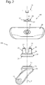
figure 2 is an exploded side plan view according to a second side of the extractable assembly group for the wheel of the luggage; -
figure 3 is an exploded top perspective view of the extractable assembly group for one wheel of a luggage; -
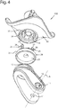
figure 4 is an exploded bottom perspective view of the extractable assembly group for one wheel of a luggage; -
figure 5 is a plan view of the rapid engaging mechanism in the engaging position between said support for said fork and said bracket; -
figure 6 shows a top perspective view of the bracket; -
figure 7 shows a top perspective view of the extractable assembly group for one wheel of a luggage according to the present invention comprising an alternative hexagonal shape pushbutton and comprising an alternative hexagonal shape pin for rotatably mounting the wheel with the fork; -
figure 8 shows a side view of the extractable assembly group offigure 7 ; -
figure 9 shows an other side view of the extractable assembly group offigure 7 ; -
figure 10 shows a front view of the extractable assembly group offigure 7 ; -
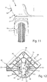
figure 11 shows a rear view of the extractable assembly group offigure 7 ; -
figure 12 shows a plan view of the extractable assembly group offigure 7 ; -
figure 13 shows a bottom view of the extractable assembly group offigure 7 ; -
figure 14 shows a rear side top perspective view of the extractable assembly group offigure 7 . - An
extractable assembly group 100 for one wheel of a luggage is shown with reference to the above-mentioned figures. - The
assembly group 100 comprises afork 10 adapted to rotatably mount at least one wheel about a first geometrical axis A, asupport 20 for the rotation of saidfork 10 adapted to rotatably mount saidfork 10 about a substantially vertical geometrical axis V, which is perpendicular to said first geometrical axis A, abracket 30 adapted to separably mount saidsupport 20 for saidfork 10, wherein thebracket 30 is mountable with the luggage. - The bracket separably mounts said support 20 by means of an
engaging mechanism 40 of theassembly group 100, which passes from an engaging position between saidsupport 20 and saidbracket 30 and an unengaging position between saidsupport 20 and saidbracket 30, which allows a separation between saidsupport 20 and saidbracket 30. - The rapid
engaging mechanism 40 comprises aslider 50, apushbutton 51 and anelastic recall element 60. Theslider 50 is slidably mounted with seats of saidbracket 30 and with seats ofprotrusions 25 of saidsupport 20 for saidfork 10, acover 70 adapted to keep saidengaging mechanism 40 in position. - As shown in particular in
figures 1-4 , thefork 10 comprises two throughholes 11 along the first geometrical axis of rotation A adapted to mount a rotating axis for at least one wheel of a luggage. The first geometrical axis of rotation A of the wheels will be, in normal conditions of use, substantially parallel to the ground. - The
fork 10 comprises anupper portion 12 comprising aseat 15 for housing a plurality of rotation elements, such as, for example, ball-bearings and/or rotation cylinders. - The
support 20 for the rotation of saidfork 10 comprises alower portion 21, which rotatably mounts theupper portion 12 of thefork 10. Thelower portion 21 of thesupport 20 comprises aseat 23 complementary to theseat 15 of theupper portion 12 of thefork 10, which is adapted to house said plurality of rotation elements. Theupper portion 12 of thefork 10 mounted with thelower portion 21 of thesupport 20 for the rotation of saidfork 10 forms aseat fork 10 can rotate with respect to thesupport 20 about said vertical geometrical axis V, which, with the device assembled to a luggage, in normal use, will be substantially perpendicular to the ground. - The
support 20 for the rotation of saidfork 10 comprises anupper portion 24 from which twoprotrusions 25 of thesupport 20 rise upwards along the vertical geometrical axis V. - The
upper portion 24 of saidsupport 20 comprises an upper face, which forms a geometrical ring, which identifies a transverse geometrical plane perpendicular to said vertical geometrical axis V, wherein the vertical geometrical axis V passes through the geometrical centre of said geometrical ring. The twoprotrusions 25 rise up starting from the geometrical ring of theupper face 24 upwards along two directions parallel to said vertical geometrical axis V. - Each
protrusion 25 of said twoprotrusions 25 of thesupport 20 for the rotation of thefork 10 comprises afirst portion 26 and asecond portion 27. Thefirst portion 26 of theprotrusion 25 extends from theupper portion 24 and rises up to thesecond portion 27 of theprotrusion 25. Thesecond portion 27 of theprotrusion 25 is an upper end of theprotrusion 25. Thesecond portion 27 of theprotrusion 25 comprises at least one transverse dimension greater than at least one transverse dimension of thefirst portion 26 of theprotrusion 25. The transverse dimensions of the first 26 and second 27 portion are measured on a geometrical plane perpendicular to the vertical geometrical axis V. - As shown in particular in
figures 1 and3 , the transverse dimension of thesecond portion 27 of theprotrusion 25, which is greater than the transverse dimension of thefirst portion 26 of theprotrusion 25 extends towards an inner space comprised between the twoprotrusions 25 towards the vertical geometrical axis V. The transverse dimension of thefirst portion 26 of theprotrusion 25 instead remains constant, thefirst portion 26 rising upwards along the vertical geometrical axis V. - Said at least one transverse dimension greater than the
second portion 27 is an engagement means for said at least oneprotrusion 25. - The sliding seat of said
slider 50 is identified by the space identified between different transverse dimensions of the first 26 and the second 27 portion of theprotrusions 25. - At least one of the two
protrusions 25 comprises aguide member 22. As shown in particular infigures 3 and5 theguide member 22 is provided on bothprotrusions 25 of thesupport 20. Theguide member 22 is a groove hollowed out in the outer surface of theprotrusion 25. Theguide member 22 is arranged along a direction parallel to the vertical geometrical axis V. - As shown in particular in
figure 6 , thebracket 30 comprises anupper portion 38, which is mountable with a lower portion of the luggage. Theupper portion 38 comprises a plurality ofseats 39 for connection elements between thebracket 30 and the luggage, such as, for example, threaded holes for fastening screws between thebracket 30 and the luggage or seats for fastening elements between thebracket 30 and the luggage. Fiveseats 39 for connection elements between thebracket 30 and the luggage are shown infigures 5 and6 . - As shown in particular in
figures 4 and6 thebracket 30 comprises alower portion 37 comprising two lower pass-throughopenings 34 adapted for the passage of said twoprotrusions 25 of thesupport 20 for the rotation of thefork 10. - Each pass-through opening 34 of the
bracket 30 allows the passage of both thefirst portion 26 and thesecond portion 27 of theprotrusion 25 of thesupport 20. - The
protrusions 25 are inserted through the pass-throughopenings 34 of thebracket 30 from the bottom upwards in the direction of the vertical geometrical axis V. - When the
protrusions 25 of thesupport 20 are inserted in the pass-throughopenings 34 of thebracket 30, theupper portion 24 of thesupport 20 is in abutment against thelower portion 37 of thebracket 30. - The
slider 50 slides along a substantially perpendicular direction with respect to the vertical geometrical axis V and is adapted to cause theengaging mechanism 40 to pass from an engaging position between saidsupport 20 and saidbracket 30 and an unengaging position between saidsupport 20 and saidbracket 30, adapted to allow a separation between saidsupport 20 and saidbracket 30. - The engaging position of the engaging
mechanism 40 prevents afork 10 andsupport 20 group from being removed from thebracket 30. - The unengaging position of the engaging
mechanism 40 allows thefork 10 andsupport 20 group to be removed from thebracket 30. - The
first portion 26 of theprotrusion 25 is a seat for a sliding of theslider 50 between the engaging position and the unengaging position of the engagingmechanism 40. - Said
slider 50 comprises aportion 57, which comprises at least one transverse dimension greater than transverse dimensions of other portions of saidslider 50. Saidportion 57 is an engagement means for saidslider 50. Transverse dimensions are measured on a geometrical plane perpendicular to said vertical geometrical axis V. - As shown in particular in
figures 1-3 ,5 saidportion 57 of saidslider 50 extends outwardly from saidslider 50. - The engaging position of the engaging
mechanism 40 provides for thesecond portion 27 of theprotrusion 25 being in abutment with at least one portion of theslider 50, which serves as an engagement means so that thefork 10 andsupport 20 group cannot be removed from thebracket 30 sliding along the vertical geometrical axis V. - The unengaging position of the engaging
mechanism 40 provides for thesecond portion 27 of theprotrusion 25 and theslider 50 not being in abutment between each other and thefork 10 andsupport 20 group being able to be removed from thebracket 30 sliding in the direction of the vertical geometrical axis V downwards without interfering with theslider 50. - As shown in particular in
figure 5 an upper face of theportion 57 of theslider 50 is in abutment against a lower face of the transverse dimension greater than thesecond portion 27 of theprotrusion 25 when theslider 50 is in the engagement position, so that thesupport 20 cannot slide downwards along the vertical direction identified by said vertical geometrical axis V. - Said
slider 50 comprises a pass-throughopening 53 as shown in particular infigures 3 and5 . Saidbracket 30 comprises aguide protrusion 33, which rises from anupper portion 31 of thebracket 30 upwards along the vertical geometrical axis. Theguide protrusion 33 slidably mounts saidslider 50, in fact, saidguide protrusion 33 passes inside said pass-throughopening 53 of saidslider 30. - Said
bracket 30 comprises a pass-throughopening 35 adapted to allow at least one portion of saidpushbutton 51 of saidslider 50 to pass therethrough. Thepushbutton 51 is slidably mounted with said pass-throughopening 35 of saidbracket 30. Thepushbutton 51 is adapted to be pushed by a user. Thepushbutton 51 is a protrusion of theslider 50, which extends along a transverse direction which is perpendicular to the direction of the vertical geometrical axis V. - The
elastic recall element 60 of theslider 50 comprises afirst end 61 mounted with saidslider 50 and asecond end 62 in abutment against awall 36 of saidbracket 30. Thefirst end 61 of theelastic recall element 60 is mounted above aprotrusion 52 of saidslider 50, wherein saidprotrusion 52 of saidslider 50 is arranged along the same transverse direction of thepushbutton 51, but toward the opposite verse. Theelastic recall element 60 passes from a position of maximum elongation, which corresponds to said engagement position of theslider 50, to a position of minimum elongation, which corresponds to said disengagement position of saidslider 50. - Said
bracket 30 comprises twoguide members 32, which engage withrespective guide members 22 of theprotrusions 25 of thesupport 20 so that thesupport 20 can slide in a vertical direction along the vertical geometrical axis V to be removed. - The
bracket 30 comprises acover 70 adapted to keep theslider 50 in position, also when theslider 50 is in the unengaging position. Thecover 70 comprises a pass-throughopening 73, which allows a screw to be screwed to keep thecover 70 and theguide protrusion 33 of thebracket 30 together. Thecover 70 is in abutment with theslider 50 so as to prevent it from coming out of its seat. - As regards operation, starting from the engagement position of the
slider 50, a user pushes thepushbutton 51 causing theelastic recall element 60 to pass from the position of maximum elongation to the position of minimum elongation and causing theslider 50 to pass into the disengagement position, thus allowing theprotrusions 25 to slide through the lower pass-throughopenings 34 of thebracket 30 so that thesupport 20 is separated from thebracket 30. - In order to engage the
support 20 with thebracket 30 again a user must push thepushbutton 51 so that there are no engagement means preventing the insertion of theprotrusions 25. Once theprotrusions 25 have been inserted through the lower pass-throughopenings 34 of thebracket 30, the user stops pushing thepushbutton 51 causing theelastic recall element 60 to pass from the position of minimum elongation to the position of maximum elongation and theslider 50 from the disengagement position to the engagement position so that engagement means 57, 27 of theslider 50 and thesupport 20 are mutually engaged to prevent the removal of thesupport 20 from thebracket 30. - Alternatively, said
protrusion 25 comprises at least one alternative engagement means and saidslider 50 comprises at least one alternative engagement means. Said slider passes from at least one engagement position between said at least one engagement means of saidslider 50 and said at least one engagement means of said at least oneprotrusion 25, which corresponds to said engaging position between saidsupport 20 and saidbracket 30, and at least one disengagement position between said at least one engagement means of saidslider 50 and said at least one engagement means of said at least oneprotrusion 25, which corresponds to said unengaging position between saidsupport 20 and saidbracket 30. - Alternatively, it is possible to provides for the
protrusion 25 of thesupport 20 passing through the pass-throughopening 53 of theslider 50 and the pass-throughopening 53 of theslider 50 comprising theportion 57, which reduces the transverse dimensions of the pass-throughopening 53 so that, in the engaging position, thesecond portion 27 of theprotrusion 25 cannot pass through the pass-throughopening 53, while, in the unengaging position of theslider 50, thesecond portion 27 of theprotrusion 25 can pass through the pass-throughopening 53 of theslider 50, which has greater transverse dimensions.
Claims (7)
- An extractable assembly group (100) for at least one wheel of a luggage comprisingat least one fork (10) adapted to rotatably mount said at least one luggage wheel,a support (20) for said fork (10) adapted to rotatably mount said fork (10) about a vertical geometrical axis (V),a bracket (30) adapted to separably mount said support (20) by means of a rapid engaging mechanism (40), adapted to pass from an engaging position between said support (20) and said bracket (30) to an unengaging position between said support (20) and said bracket (30), adapted to allow a separation between said support (20) and said bracket (30),wherein said bracket (30) is adapted to be assembled to said luggage,wherein said support (20) comprises at least one protrusion (25), comprising at least one engagement means,wherein said rapid engaging mechanism (40) comprises a slider (50), slidably associated to said bracket (30),said slider (50) comprising at least one engagement means,said slider (50) being adapted to pass from an engagement position between said at least one engagement means of said slider (50) and said at least one engagement means of said at least one protrusion (25), which corresponds to said engaging position between said support (20) and said bracket (30), to a disengagement position between said at least one engagement means of said slider (50) and said at least one engagement means of said at least one protrusion (25), which corresponds to said unengaging position between said support (20) and said bracket (30),wherein said at least one protrusion (25), comprises a first portion (26) and a second portion (27), said second portion (27) of said at least one protrusion (25) comprising at least one transverse dimension greater than at least one transverse dimension of said first portion (26) of said at least one protrusion (25), said at least one transverse dimension of the second portion (27) is said at least one engagement means of said at least one protrusion (25), wherein transverse dimensions are measured on a geometrical plane perpendicular to said vertical geometrical axis (V),wherein said support (20) comprises an upper portion (24) from which said at least one protrusion (25) rises upwards along a direction parallel to said vertical geometrical axis (V), said first portion (26) of said at least one protrusion (25) extends from the upper portion (24) and rises up until said second portion (27) of said at least one protrusion (25), said second portion (27) of said at least one protrusion (25) is an upper end of said at least one protrusion (25),wherein said upper portion (24) of said support (20) comprises an upper face forming a geometrical ring which identifies a transverse geometrical plane perpendicular to said vertical geometrical axis (V), wherein the vertical geometrical axis (V) passes through the geometrical centre of said geometrical ring,characterised in that said support (20) comprises two protrusions (25) of said at least one protrusion (25), said two protrusions (25) rise up starting from the geometrical ring of an upper face of the upper portion (24) upwards along two directions parallel to said vertical geometrical axis (V), each of said at least one transverse dimension greater than said second portion (27) is directed towards an inner space between said two protrusions (25).
- The assembly group (100) according to claim 1, characterized in that said slider (50) comprises a portion (57), which comprises at least one transverse dimension greater than transverse dimensions of other portions of said slider (50), said portion (57) is said at least one engagement means of said slider (50), wherein transverse dimensions are measured on a geometrical plane perpendicular to said vertical geometrical axis (V).
- The assembly group (100) according to claim 2, characterized in that said portion (57) of said slider (50) projects outwardly of said slider (50).
- The assembly group (100) according to any one of claims 1-3, characterized in that said slider (50) comprises a pass-through opening (53), in that said bracket (30) comprises a guide protrusion (33), which slidably mounts said slider (50), said guide protrusion (33) passing within said pass-through opening (53) of said slider (50).
- The assembly group (100) according to any one of claims 1-4, characterized in that said slider (50) comprises a pushbutton (51), said bracket (30) comprises a pass-through opening (35), said pushbutton (51) of said slider (50) is slidably mounted with said pass-through opening (35) of said bracket (30), wherein said pushbutton (51) is adapted to be pushed by a user.
- The assembly group (100) according to any one of claims 1-5, characterized in that said slider (50) comprises an elastic recall element (60), comprising a first end (61) mounted with said slider (50) and a second end (62) in abutment against a wall (36) of said bracket (30), said elastic recall element (60) being adapted to pass from a position of maximum elongation, which corresponds to said engagement position of the slider (50), to a position of minimum elongation, which corresponds to said disengagement position of said slider (50).
- The assembly group (100) according to any one of claims 1-6, characterized in that said bracket (30) comprises at least one lower pass-through opening (34), said at least one lower pass-through opening (34) having dimensions adapted to allow the passage of said at least one protrusion (25) of said support (20).
Applications Claiming Priority (2)
| Application Number | Priority Date | Filing Date | Title |
|---|---|---|---|
| IT102019000003967A IT201900003967A1 (en) | 2019-03-19 | 2019-03-19 | REMOVABLE ASSEMBLY GROUP FOR ONE WHEEL OF A SUITCASE. |
| CN201920799905.8U CN210870194U (en) | 2019-03-19 | 2019-05-30 | Extractable assembly group for at least one luggage wheel |
Publications (2)
| Publication Number | Publication Date |
|---|---|
| EP3721744A1 EP3721744A1 (en) | 2020-10-14 |
| EP3721744B1 true EP3721744B1 (en) | 2021-11-24 |
Family
ID=67002182
Family Applications (1)
| Application Number | Title | Priority Date | Filing Date |
|---|---|---|---|
| EP20163371.6A Active EP3721744B1 (en) | 2019-03-19 | 2020-03-16 | Extractable assembly group for one wheel of a luggage |
Country Status (4)
| Country | Link |
|---|---|
| EP (1) | EP3721744B1 (en) |
| CN (1) | CN210870194U (en) |
| HU (1) | HUE059111T2 (en) |
| IT (1) | IT201900003967A1 (en) |
Family Cites Families (3)
| Publication number | Priority date | Publication date | Assignee | Title |
|---|---|---|---|---|
| FR2899776B1 (en) * | 2006-04-18 | 2008-07-25 | Delsey Sa | REMOVABLE WHEEL SYSTEM FOR LUGGAGE |
| CN104149547A (en) * | 2014-08-04 | 2014-11-19 | 德清普洛旺斯箱包有限公司 | Detachable universal wheel |
| CN206101908U (en) * | 2016-10-25 | 2017-04-19 | 梅显尧 | Detachable case and bag wheel subassembly |
-
2019
- 2019-03-19 IT IT102019000003967A patent/IT201900003967A1/en unknown
- 2019-05-30 CN CN201920799905.8U patent/CN210870194U/en active Active
-
2020
- 2020-03-16 EP EP20163371.6A patent/EP3721744B1/en active Active
- 2020-03-16 HU HUE20163371A patent/HUE059111T2/en unknown
Also Published As
| Publication number | Publication date |
|---|---|
| CN210870194U (en) | 2020-06-30 |
| IT201900003967A1 (en) | 2020-09-19 |
| HUE059111T2 (en) | 2022-10-28 |
| EP3721744A1 (en) | 2020-10-14 |
Similar Documents
| Publication | Publication Date | Title |
|---|---|---|
| US9835398B2 (en) | Firearm trigger group module with pivoting element non-coaxial to assembly pin and method of installing a trigger group module | |
| EP3214493B1 (en) | Lens limiting assembly, camera body, and camera | |
| AU2015252083B2 (en) | Assembly For Connecting A Roof Rack To A Vehicle | |
| KR101920589B1 (en) | Stock assembly | |
| US7939795B2 (en) | Encoder device and gapping and centering device for an encoder device | |
| CN106218322A (en) | A kind of connecting shaft device and bicycle | |
| KR102058895B1 (en) | Clearance compensator of yoke | |
| US9598023B2 (en) | Bicycle-fork support device | |
| US11668333B2 (en) | Clamp mechanism and related tray | |
| US7065843B1 (en) | Safety belt latch for car | |
| EP3721744B1 (en) | Extractable assembly group for one wheel of a luggage | |
| EP2743520B1 (en) | Secure button with indicator | |
| EP2409614B1 (en) | Rotary lock catch and frying and baking apparatus including rotary lock catch | |
| EP3268177B1 (en) | Power tool with drop arm orbit bracket | |
| US11571995B2 (en) | Quick-release seat fitting | |
| EP3032125B2 (en) | Disc brake and components thereof | |
| US20030085389A1 (en) | Longitudinal entry clip for use in a vehicle jack system and a vehicle jack system incorporating the same | |
| CN105996275B (en) | A kind of coupling mechanism | |
| US20100175231A1 (en) | Device with Releasable Attachment Means | |
| EP2383175B1 (en) | Operation mechanism for controlling front suspension system | |
| EP3268175B1 (en) | Power tool with cammed throat plate | |
| WO2023092131A1 (en) | Hard hat accessory bracket | |
| EP3279073A1 (en) | Cable control device for bicycle | |
| EP2017129B1 (en) | Support foot for vehicle roof carriers bars | |
| CA2931437A1 (en) | Wheel fork |
Legal Events
| Date | Code | Title | Description |
|---|---|---|---|
| PUAI | Public reference made under article 153(3) epc to a published international application that has entered the european phase |
Free format text: ORIGINAL CODE: 0009012 |
|
| STAA | Information on the status of an ep patent application or granted ep patent |
Free format text: STATUS: THE APPLICATION HAS BEEN PUBLISHED |
|
| AK | Designated contracting states |
Kind code of ref document: A1 Designated state(s): AL AT BE BG CH CY CZ DE DK EE ES FI FR GB GR HR HU IE IS IT LI LT LU LV MC MK MT NL NO PL PT RO RS SE SI SK SM TR |
|
| AX | Request for extension of the european patent |
Extension state: BA ME |
|
| STAA | Information on the status of an ep patent application or granted ep patent |
Free format text: STATUS: REQUEST FOR EXAMINATION WAS MADE |
|
| 17P | Request for examination filed |
Effective date: 20210402 |
|
| RBV | Designated contracting states (corrected) |
Designated state(s): AL AT BE BG CH CY CZ DE DK EE ES FI FR GB GR HR HU IE IS IT LI LT LU LV MC MK MT NL NO PL PT RO RS SE SI SK SM TR |
|
| GRAP | Despatch of communication of intention to grant a patent |
Free format text: ORIGINAL CODE: EPIDOSNIGR1 |
|
| STAA | Information on the status of an ep patent application or granted ep patent |
Free format text: STATUS: GRANT OF PATENT IS INTENDED |
|
| INTG | Intention to grant announced |
Effective date: 20210914 |
|
| GRAS | Grant fee paid |
Free format text: ORIGINAL CODE: EPIDOSNIGR3 |
|
| GRAA | (expected) grant |
Free format text: ORIGINAL CODE: 0009210 |
|
| STAA | Information on the status of an ep patent application or granted ep patent |
Free format text: STATUS: THE PATENT HAS BEEN GRANTED |
|
| AK | Designated contracting states |
Kind code of ref document: B1 Designated state(s): AL AT BE BG CH CY CZ DE DK EE ES FI FR GB GR HR HU IE IS IT LI LT LU LV MC MK MT NL NO PL PT RO RS SE SI SK SM TR |
|
| REG | Reference to a national code |
Ref country code: GB Ref legal event code: FG4D |
|
| REG | Reference to a national code |
Ref country code: AT Ref legal event code: REF Ref document number: 1449178 Country of ref document: AT Kind code of ref document: T Effective date: 20211215 |
|
| REG | Reference to a national code |
Ref country code: DE Ref legal event code: R096 Ref document number: 602020001066 Country of ref document: DE |
|
| REG | Reference to a national code |
Ref country code: IE Ref legal event code: FG4D |
|
| REG | Reference to a national code |
Ref country code: LT Ref legal event code: MG9D |
|
| REG | Reference to a national code |
Ref country code: NL Ref legal event code: MP Effective date: 20211124 |
|
| REG | Reference to a national code |
Ref country code: AT Ref legal event code: MK05 Ref document number: 1449178 Country of ref document: AT Kind code of ref document: T Effective date: 20211124 |
|
| PG25 | Lapsed in a contracting state [announced via postgrant information from national office to epo] |
Ref country code: RS Free format text: LAPSE BECAUSE OF FAILURE TO SUBMIT A TRANSLATION OF THE DESCRIPTION OR TO PAY THE FEE WITHIN THE PRESCRIBED TIME-LIMIT Effective date: 20211124 Ref country code: LT Free format text: LAPSE BECAUSE OF FAILURE TO SUBMIT A TRANSLATION OF THE DESCRIPTION OR TO PAY THE FEE WITHIN THE PRESCRIBED TIME-LIMIT Effective date: 20211124 Ref country code: FI Free format text: LAPSE BECAUSE OF FAILURE TO SUBMIT A TRANSLATION OF THE DESCRIPTION OR TO PAY THE FEE WITHIN THE PRESCRIBED TIME-LIMIT Effective date: 20211124 Ref country code: BG Free format text: LAPSE BECAUSE OF FAILURE TO SUBMIT A TRANSLATION OF THE DESCRIPTION OR TO PAY THE FEE WITHIN THE PRESCRIBED TIME-LIMIT Effective date: 20220224 Ref country code: AT Free format text: LAPSE BECAUSE OF FAILURE TO SUBMIT A TRANSLATION OF THE DESCRIPTION OR TO PAY THE FEE WITHIN THE PRESCRIBED TIME-LIMIT Effective date: 20211124 |
|
| PG25 | Lapsed in a contracting state [announced via postgrant information from national office to epo] |
Ref country code: IS Free format text: LAPSE BECAUSE OF FAILURE TO SUBMIT A TRANSLATION OF THE DESCRIPTION OR TO PAY THE FEE WITHIN THE PRESCRIBED TIME-LIMIT Effective date: 20220324 Ref country code: SE Free format text: LAPSE BECAUSE OF FAILURE TO SUBMIT A TRANSLATION OF THE DESCRIPTION OR TO PAY THE FEE WITHIN THE PRESCRIBED TIME-LIMIT Effective date: 20211124 Ref country code: PT Free format text: LAPSE BECAUSE OF FAILURE TO SUBMIT A TRANSLATION OF THE DESCRIPTION OR TO PAY THE FEE WITHIN THE PRESCRIBED TIME-LIMIT Effective date: 20220324 Ref country code: PL Free format text: LAPSE BECAUSE OF FAILURE TO SUBMIT A TRANSLATION OF THE DESCRIPTION OR TO PAY THE FEE WITHIN THE PRESCRIBED TIME-LIMIT Effective date: 20211124 Ref country code: NO Free format text: LAPSE BECAUSE OF FAILURE TO SUBMIT A TRANSLATION OF THE DESCRIPTION OR TO PAY THE FEE WITHIN THE PRESCRIBED TIME-LIMIT Effective date: 20220224 Ref country code: NL Free format text: LAPSE BECAUSE OF FAILURE TO SUBMIT A TRANSLATION OF THE DESCRIPTION OR TO PAY THE FEE WITHIN THE PRESCRIBED TIME-LIMIT Effective date: 20211124 Ref country code: LV Free format text: LAPSE BECAUSE OF FAILURE TO SUBMIT A TRANSLATION OF THE DESCRIPTION OR TO PAY THE FEE WITHIN THE PRESCRIBED TIME-LIMIT Effective date: 20211124 Ref country code: HR Free format text: LAPSE BECAUSE OF FAILURE TO SUBMIT A TRANSLATION OF THE DESCRIPTION OR TO PAY THE FEE WITHIN THE PRESCRIBED TIME-LIMIT Effective date: 20211124 Ref country code: GR Free format text: LAPSE BECAUSE OF FAILURE TO SUBMIT A TRANSLATION OF THE DESCRIPTION OR TO PAY THE FEE WITHIN THE PRESCRIBED TIME-LIMIT Effective date: 20220225 |
|
| PG25 | Lapsed in a contracting state [announced via postgrant information from national office to epo] |
Ref country code: SM Free format text: LAPSE BECAUSE OF FAILURE TO SUBMIT A TRANSLATION OF THE DESCRIPTION OR TO PAY THE FEE WITHIN THE PRESCRIBED TIME-LIMIT Effective date: 20211124 Ref country code: SK Free format text: LAPSE BECAUSE OF FAILURE TO SUBMIT A TRANSLATION OF THE DESCRIPTION OR TO PAY THE FEE WITHIN THE PRESCRIBED TIME-LIMIT Effective date: 20211124 Ref country code: RO Free format text: LAPSE BECAUSE OF FAILURE TO SUBMIT A TRANSLATION OF THE DESCRIPTION OR TO PAY THE FEE WITHIN THE PRESCRIBED TIME-LIMIT Effective date: 20211124 Ref country code: ES Free format text: LAPSE BECAUSE OF FAILURE TO SUBMIT A TRANSLATION OF THE DESCRIPTION OR TO PAY THE FEE WITHIN THE PRESCRIBED TIME-LIMIT Effective date: 20211124 Ref country code: EE Free format text: LAPSE BECAUSE OF FAILURE TO SUBMIT A TRANSLATION OF THE DESCRIPTION OR TO PAY THE FEE WITHIN THE PRESCRIBED TIME-LIMIT Effective date: 20211124 Ref country code: DK Free format text: LAPSE BECAUSE OF FAILURE TO SUBMIT A TRANSLATION OF THE DESCRIPTION OR TO PAY THE FEE WITHIN THE PRESCRIBED TIME-LIMIT Effective date: 20211124 Ref country code: CZ Free format text: LAPSE BECAUSE OF FAILURE TO SUBMIT A TRANSLATION OF THE DESCRIPTION OR TO PAY THE FEE WITHIN THE PRESCRIBED TIME-LIMIT Effective date: 20211124 |
|
| REG | Reference to a national code |
Ref country code: DE Ref legal event code: R097 Ref document number: 602020001066 Country of ref document: DE |
|
| PLBE | No opposition filed within time limit |
Free format text: ORIGINAL CODE: 0009261 |
|
| STAA | Information on the status of an ep patent application or granted ep patent |
Free format text: STATUS: NO OPPOSITION FILED WITHIN TIME LIMIT |
|
| REG | Reference to a national code |
Ref country code: HU Ref legal event code: AG4A Ref document number: E059111 Country of ref document: HU |
|
| PG25 | Lapsed in a contracting state [announced via postgrant information from national office to epo] |
Ref country code: MC Free format text: LAPSE BECAUSE OF FAILURE TO SUBMIT A TRANSLATION OF THE DESCRIPTION OR TO PAY THE FEE WITHIN THE PRESCRIBED TIME-LIMIT Effective date: 20211124 Ref country code: AL Free format text: LAPSE BECAUSE OF FAILURE TO SUBMIT A TRANSLATION OF THE DESCRIPTION OR TO PAY THE FEE WITHIN THE PRESCRIBED TIME-LIMIT Effective date: 20211124 |
|
| 26N | No opposition filed |
Effective date: 20220825 |
|
| PG25 | Lapsed in a contracting state [announced via postgrant information from national office to epo] |
Ref country code: SI Free format text: LAPSE BECAUSE OF FAILURE TO SUBMIT A TRANSLATION OF THE DESCRIPTION OR TO PAY THE FEE WITHIN THE PRESCRIBED TIME-LIMIT Effective date: 20211124 |
|
| PG25 | Lapsed in a contracting state [announced via postgrant information from national office to epo] |
Ref country code: LU Free format text: LAPSE BECAUSE OF NON-PAYMENT OF DUE FEES Effective date: 20220316 Ref country code: IE Free format text: LAPSE BECAUSE OF NON-PAYMENT OF DUE FEES Effective date: 20220316 Ref country code: FR Free format text: LAPSE BECAUSE OF NON-PAYMENT OF DUE FEES Effective date: 20220331 |
|
| PG25 | Lapsed in a contracting state [announced via postgrant information from national office to epo] |
Ref country code: IT Free format text: LAPSE BECAUSE OF FAILURE TO SUBMIT A TRANSLATION OF THE DESCRIPTION OR TO PAY THE FEE WITHIN THE PRESCRIBED TIME-LIMIT Effective date: 20211124 |
|
| REG | Reference to a national code |
Ref country code: CH Ref legal event code: PL |
|
| PG25 | Lapsed in a contracting state [announced via postgrant information from national office to epo] |
Ref country code: LI Free format text: LAPSE BECAUSE OF NON-PAYMENT OF DUE FEES Effective date: 20230331 Ref country code: CH Free format text: LAPSE BECAUSE OF NON-PAYMENT OF DUE FEES Effective date: 20230331 |
|
| PG25 | Lapsed in a contracting state [announced via postgrant information from national office to epo] |
Ref country code: MK Free format text: LAPSE BECAUSE OF FAILURE TO SUBMIT A TRANSLATION OF THE DESCRIPTION OR TO PAY THE FEE WITHIN THE PRESCRIBED TIME-LIMIT Effective date: 20211124 Ref country code: CY Free format text: LAPSE BECAUSE OF FAILURE TO SUBMIT A TRANSLATION OF THE DESCRIPTION OR TO PAY THE FEE WITHIN THE PRESCRIBED TIME-LIMIT Effective date: 20211124 |
|
| PG25 | Lapsed in a contracting state [announced via postgrant information from national office to epo] |
Ref country code: MT Free format text: LAPSE BECAUSE OF FAILURE TO SUBMIT A TRANSLATION OF THE DESCRIPTION OR TO PAY THE FEE WITHIN THE PRESCRIBED TIME-LIMIT Effective date: 20211124 |
|
| GBPC | Gb: european patent ceased through non-payment of renewal fee |
Effective date: 20240316 |
|
| PG25 | Lapsed in a contracting state [announced via postgrant information from national office to epo] |
Ref country code: GB Free format text: LAPSE BECAUSE OF NON-PAYMENT OF DUE FEES Effective date: 20240316 |
|
| PG25 | Lapsed in a contracting state [announced via postgrant information from national office to epo] |
Ref country code: GB Free format text: LAPSE BECAUSE OF NON-PAYMENT OF DUE FEES Effective date: 20240316 |
|
| PGFP | Annual fee paid to national office [announced via postgrant information from national office to epo] |
Ref country code: DE Payment date: 20260102 Year of fee payment: 7 |
|
| PGFP | Annual fee paid to national office [announced via postgrant information from national office to epo] |
Ref country code: BE Payment date: 20260105 Year of fee payment: 7 |
|
| PGFP | Annual fee paid to national office [announced via postgrant information from national office to epo] |
Ref country code: HU Payment date: 20260213 Year of fee payment: 7 |
|
| PGFP | Annual fee paid to national office [announced via postgrant information from national office to epo] |
Ref country code: TR Payment date: 20260313 Year of fee payment: 7 |