EP3721701A1 - Ballenpresse - Google Patents
Ballenpresse Download PDFInfo
- Publication number
- EP3721701A1 EP3721701A1 EP20151441.1A EP20151441A EP3721701A1 EP 3721701 A1 EP3721701 A1 EP 3721701A1 EP 20151441 A EP20151441 A EP 20151441A EP 3721701 A1 EP3721701 A1 EP 3721701A1
- Authority
- EP
- European Patent Office
- Prior art keywords
- press
- profile
- pressing
- chamber
- inlet
- Prior art date
- Legal status (The legal status is an assumption and is not a legal conclusion. Google has not performed a legal analysis and makes no representation as to the accuracy of the status listed.)
- Granted
Links
Images

Classifications
-
- A—HUMAN NECESSITIES
- A01—AGRICULTURE; FORESTRY; ANIMAL HUSBANDRY; HUNTING; TRAPPING; FISHING
- A01F—PROCESSING OF HARVESTED PRODUCE; HAY OR STRAW PRESSES; DEVICES FOR STORING AGRICULTURAL OR HORTICULTURAL PRODUCE
- A01F15/00—Baling presses for straw, hay or the like
- A01F15/08—Details
- A01F15/0825—Regulating or controlling density or shape of the bale
Definitions
- the present invention relates to a baler according to the preamble of claim 1.
- Balers are used in agriculture to pick up straw-like crops such as straw, hay, grass or the like deposited in a swath and to press them into bales.
- baling presses have various working units that are used to convey and / or process the crop as required.
- the working units are usually in drive connection with a central drive train of the baling press and are usually driven by a tractor to which the baling press is attached.
- a baling press comprises a pressing chamber in which a pressing piston can be moved in an oscillating manner for compressing the crop into a bale.
- An antechamber upstream of the baling chamber has an inlet area into which crop material picked up by a receiving device, such as a pick-up, enters, and an outlet area which opens into the baling chamber.
- a rake can be switched between a collecting stroke movement that compresses the crop in the antechamber and a filling stroke movement that shifts the crop from the antechamber into the downstream baling chamber.
- the task of the antechamber is to collect as homogeneous a package of harvested material as possible before it is transported into the baling chamber by the packer.
- the individual crop packages are each pressed against one another by a pressing piston that moves in an oscillating manner condensed.
- the bale grows approximately by the thickness of the crop package, so that the bale in the baling chamber grows continuously in a rearward direction of the press.
- a completely pressed and tied bale still acts at least partially as an abutment for the formation of a new bale and is ejected from the rear of the press.
- the pressing chamber is usually conical, so that forces can be exerted on the crop and / or the bale laterally and / or in the vertical direction.
- the cross section of the press chamber tapers in the direction of the ejection opening of the press chamber at the rear of the press.
- the side walls and the upper side are usually designed to be displaceable, as a result of which the pressure acting laterally on the bale in the pressing chamber can be varied.
- the aim is to produce bales that are as uniform and dimensionally stable as possible, depending on the crop and harvesting conditions, so that they can be transported and stored efficiently.
- the corners of the bales are often not dimensionally accurate, since there is no reliable shaping of the bale due to the variable side walls and top. When the bales are subsequently transported, this can mean that the individual bales require more space than planned and thus more transports and more storage space are necessary.
- An agricultural baling press in particular a square baling press, has at least one working unit for processing and / or conveying
- the pressing chamber having two opposing side walls and a pressure plate delimiting the pressing chamber at the top, a corner profile extending at least along part of the pressing chamber being arranged between a side wall and the upper pressure plate.
- the corner profile has at least one first press profile with a first press surface facing the press chamber for interaction with the crop, and a first inlet area with a first inlet surface, the first inlet surface adjoining the first pressing surface and being formed at an angle to it , wherein an end of the first inlet surface facing away from the first pressing surface is further spaced from the pressing chamber than the first pressing surface.
- the first press profile extends at least along part of the corner profile and / or the press chamber.
- the first run-in surface of the first run-in region is designed in such a way that it tapers essentially conically from an end on the plunger side, which is spaced apart from the first press surface, towards the first press surface.
- the inlet surface can be at least partially linear and / or partially curved between its two ends.
- the crop Due to the conically tapering inlet area, the crop is increasingly compacted, especially in the edge area along the baling chamber. This leads to increased pressure in the edge area, which improves the shape of the bale in the edge area. This enables improved dimensional accuracy of the finished bale to be achieved.
- the corner profile can preferably have a second press profile, which in particular has a second inlet area with a second inlet surface, the second inlet surface adjoining the second press surface and being formed at an angle to it, one of the second Pressing surface facing away from the end of the second inlet surface is further spaced from the pressing chamber than the second pressing surface.
- the second inlet area and the second inlet surface can be arranged on the press piston side on the corner profile and / or first press profile.
- the first and second press profiles can be arranged essentially at right angles to one another.
- the first press profile can be formed essentially vertically and the second press profile can be formed essentially horizontally.
- the second press profile can be arranged on or on the first press surface of the first press profile, wherein the second press profile can in particular extend at least along part of the corner profile, the first press profile and / or the press chamber. Due to the adjacent arrangement of the first and second press profile, the crop can be compressed particularly strongly, especially in the edge area, in particular in a vertical and / or horizontal direction, whereby the formation of the edges of the bale can be further improved.
- At least one of the press profiles can protrude further into the press chamber than a side wall and / or pressure plate arranged adjacent to it. Because at least one of the press profiles protrudes beyond an adjacent side wall and / or pressure plate into the press chamber, compression of the crop at the edges of the bale in the horizontal and / or vertical direction can be further increased and the duration of the pressure can also be extended. In this way, improved formation of the edges of the bale can be achieved.
- the corner profile and at least one press profile can be designed to be pivotable, in particular in the direction of the press chamber.
- the pressure acting on the crop can be adjusted in the edge area. This can for example be done automatically by a control device as a function of the Crop and / or the harvesting conditions such as crop moisture.
- the adjustable compression of the crop in the edge area the pressing forces acting there on the crop can be adjusted in the horizontal and / or vertical direction, whereby improved edge formation can be achieved.
- the corner profile is supported in such a way that the corner profile can be pivoted essentially parallel to a longitudinal direction of the pressing chamber and / or around a particularly vertical and / or horizontal axis of rotation.
- a parallel pivoting of the corner profile allows the pressing forces acting in the edge area over the entire area of the press profiles to be set, for example increased.
- pivoting for example about an axis of rotation arranged in a front area of the press chamber, adjacent to an inlet area, the increase in the press forces acting along the press profiles can be adjusted.
- At least one press profile in a rear area of the press chamber has an outlet area with an outlet surface, the outlet surface adjoining the pressing surface and being formed at an angle to it, with an end of the outlet surface facing away from the pressing surface further from the pressing chamber is spaced as the pressing surface.
- the first press profile is preferably designed in the form of an, in particular hollow, profile.
- the profile can have an L-shaped, U-shaped or closed cross section. This has the advantage that, with a low weight, a high degree of rigidity for transmitting high press forces can be made possible.
- the second press profile is particularly preferably designed in the form of a projection and extends in particular along part of the first press surface.
- the second press profile can be arranged on the press chamber side on the first press profile, in particular on the first press surface.
- the projection can be designed in the form of a sheet metal strip with a rectangular, elongated cross section. As a result, the second press profile can be produced inexpensively.
- the second press profile is advantageously at least partially in the form of a profile, in particular a hollow profile.
- The, in particular hollow, profile can have an L-shaped, U-shaped or closed cross section.
- the second press profile can be produced in one piece with the first press profile, for example from sheet metal. This has the advantage that, with a low weight, a high degree of rigidity for transmitting high press forces can be made possible.
- the first and / or second press profile has recesses, in particular on a side facing away from the press chamber, which interact with one of the side walls and / or the pressure plate. These recesses can be used to guide an adjacent side wall and / or the pressure plate if these are also adjusted individually to optimize the formation of the bale.
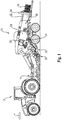
- FIG. 1 shows a schematic side view of a combination of an agricultural baler 10 in the form of a square baler and a tractor 12, the baler 10 being pulled by the tractor 12 over a field.
- the rear of the tractor 12 has a power take-off shaft 14, known per se, via which the baler 10 can be supplied with mechanical drive energy.
- the baling press 10 has working units such as a pick-up 20, a cutting rotor 22, a packer 24, and a plunger 26 through which the crop 16 is conveyed and / or processed.
- the pick-up 20 serves to pick up crop 16 lying on the field floor - mostly in the form of a so-called swath - and to feed this to the downstream conveying and / or processing units.
- the crop 16 picked up in this way reaches the cutting rotor 22, which causes the crop 16 to be further comminuted.
- the crop 16 then arrives in a feed channel in which a packer 24 performs a pre-compression of the crop 16 and a conveyance of the crop 16 into the pressing chamber 28 by means of periodic filling and collecting stroke movements.
- a pressing piston 26 is mounted such that it can move in translation and is set in oscillating movements via a pressing piston drive. Completely pressed square bales 18 are thrown from the rear of the baler 10 onto the field.
- the working units of the baling press 10, in particular the pick-up 20, the cutting rotor 22, the packer rake 24, and the press piston 26 are driven via a central drive train of the baling press 10.
- the pressing chamber 28 has two oppositely arranged side walls 30 and a pressure plate 32 delimiting the pressing chamber 28 on the upper side.
- the side walls 30 and the pressure plate 32 are supported on the outside of a frame 34 and can be pivoted or shifted in the direction of the pressing chamber 28, for example hydraulically to change the pressing forces of the side walls 30 and / or the pressure plate 32 so that a bale 18 can be formed during the repeated pressing of the plunger 26.
- the baling press 10 has a corner profile 38 between a side wall 30 and the pressure plate 32.
- the corner profile 38 has a first press profile 40 with a first press surface 44 which is arranged essentially vertically on the press chamber side and which is used to compress the crop in an edge region in an essentially horizontal direction.
- the first press profile 40 is designed in the form of a profile 60 with a U-shaped cross section.
- the first press profile 40 has at an end on the press piston side (in Fig. 2 in the foreground) a first inlet area 48 with a first inlet surface 50.
- the first inlet surface 50 is arranged adjacent to the first pressing surface 44 and is arranged further from the pressing chamber 28 at its end on the plunger side than at the end adjacent to the first pressing surface 44. As a result, a substantially conical first inlet region 48 is formed which runs along the Pressing chamber 28 enables increasing compaction of the crop 16 in the edge area.
- a second press profile 42 with a second press surface 46 is arranged on the first press surface 44 and extends along part of the first press profile 40. This is also designed as a profile 60 made of sheet metal and has a closed cross section.
- the second press profile 42 has a second inlet area 52 with a second inlet surface 54 on the plunger side.
- the second inlet surface 54 like the first inlet surface 50, forms a conically tapering second inlet area 52. This serves to better compress the crop in a substantially vertical direction in order to enable better edge shaping and dimensional accuracy of the bale.
- the side wall 30 is mounted in a front area on the press piston side so as to be pivotable about an axis of rotation 58 in order to be able to change laterally acting press forces on the crop 16.
- the pressure plate 32 on the upper side is designed in the form of a plurality of press beams 36 arranged adjacent to one another for compacting the crop.
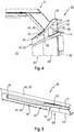
- FIG. 8 is a perspective view of the corner profile 38 from FIG Figure 2 shown.
- the corner profile 38 has a first press profile 40 which, on the press chamber side, has a substantially vertical first press surface 44 through which press forces can be transmitted to the crop in the press chamber in a substantially horizontal direction.
- the first press profile 40 is designed in the form of a U-shaped profile 60.
- the first press profile 40 has a first inlet area 48 which, when the corner profile 38 is in an assembled state, is arranged at an input area of the press chamber (not shown) on the press piston side.
- the first inlet area 48 has a first inlet surface 50 on the press chamber side, which opens flush with the surface into the adjoining first press surface 44.
- first purchase surface 50 is conical, so that it is further spaced from the press chamber 28 on the press piston side than on the press surface side.
- a press chamber side is located on the first press surface 44
- Second press profile 42 is arranged, which is designed in the form of a hollow profile 60.
- the second pressing profile 42 has an essentially horizontally designed second pressing surface 46 by means of which pressing forces can be exerted on the crop in the pressing chamber essentially in a vertical direction in order to improve the shaping of the bale edges.
- the second press profile 42 has a second inlet area 52 with a second inlet surface 54.
- the second inlet surface 54 is also designed to taper conically - in the vertical direction - and merges flush with the second pressing surface 46.
- the second press profile 42 has an outlet area 62.
- the outlet area 62 comprises an outlet surface 64 on the press chamber side, which runs back in the direction of the end of the compression chamber in the vertical direction, whereby pressing forces acting in the vertical direction on edges of a bale 18 in the outlet area 62 can be reduced compared to an area of the second pressing surface 46 Second press profile 42, recesses 66 are formed on the press chamber side, which, for example, can interact with the pressure plate (not shown) as a guide.
- a pressing chamber 28 is shown with a view to one end of the pressing chamber 28.
- the side wall 30 supported on a frame 34 has a side inlet area 56 in a front area on the plunger side, which can improve the inlet of the crop into the baling chamber 28.
- a corner profile 38 which has a first and a second press profile 40, 42, is arranged above the side wall 30.
- the first press profile 40 is designed in the form of a U-shaped profile and has a first inlet region 48 with a conically running inlet surface 50 at a front end on the press piston side. At the end of the first press profile 40, the first inlet area has a straight section 74 which runs essentially parallel to the first press surface 44.
- the straight section 74 merges into the first inlet surface 50 in the conveying direction of the crop.
- the press chamber is on the first pressing surface 50 and the first inlet surface 50, the second pressing profile 42 is arranged.
- the second press profile 42 is designed in the form of a projection 68, for example from a sheet metal strip.
- the second press profile 42 On the press piston side, the second press profile 42 has a second inlet area 52 with a second inlet surface 54.
- the second press profile 42 shown extends only along part of the first press profile 40 and ends approximately in the middle of the second press surface 46.
Landscapes
- Life Sciences & Earth Sciences (AREA)
- Environmental Sciences (AREA)
- Harvesting Machines For Specific Crops (AREA)
Abstract
Description
- Die vorliegende Erfindung betrifft eine Ballenpresse gemäß dem Oberbegriff des Anspruches 1.
- Ballenpressen werden in der Landwirtschaft dazu eingesetzt beispielsweise im Schwad abgelegtes halmartiges Erntegut wie Stroh, Heu, Gras oder dergleichen aufzunehmen und zu Ballen zu pressen. Hierzu verfügen Ballenpressen über verschiedene Arbeitsaggregate, die der erforderlichen Förderung und/oder Verarbeitung des Ernteguts dienen. Die Arbeitsaggregate stehen üblicherweise mit einem zentralen Antriebsstrang der Ballenpresse in Antriebsverbindung und werden üblicherweise von einem Schlepper, an den die Ballenpresse angehängt ist, angetrieben.
- Aus der
DE 10 2007 036293 A1 und derEP 3003007 A1 sind Ballenpressen gemäß dem Oberbegriff des Anspruches 1 bekannt. Eine Ballenpresse umfasst dabei eine Presskammer, in der ein Presskolben zur Verdichtung von Erntegut zu einem Ballen oszillierend bewegbar ist. Eine der Presskammer vorgeordnete Vorkammer weist einen Einlaufbereich, in den von einer Aufnahmevorrichtung, wie einer Pick-Up, aufgenommenes Erntegut eintritt, sowie einen Auslaufbereich, der in die Presskammer einmündet, auf. In der Vorkammer ist ein Raffer zwischen einer Erntegut in der Vorkammer verdichtenden Sammelhubbewegung und einer das Erntegut von der Vorkammer in die nachgeordnete Presskammer verlagernden Füllhubbewegung umschaltbar ist. Der Vorkammer kommt die Aufgabe zu, ein möglichst homogenes Paket an Erntegut zu sammeln, bevor dieses von dem Raffer in die Presskammer befördert wird. - In der Presskammer werden die einzelnen Erntegutpakete jeweils durch einen sich oszillierend bewegenden Presskolben gegeneinander gepresst und verdichtet. Mit jedem Hub und jedem Erntegutpaket wächst der Ballen jeweils ungefähr um die Dicke des Erntegutpaketes, wodurch der Ballen in der Presskammer kontinuierlich in eine hintere Richtung der Presse wächst. Ein fertig gepresster und gebundener Ballen wirkt zumindest teilweise noch als Widerlager für die Bildung eines neuen Ballens und wird heckseitig aus der Presse ausgeworfen. Damit die Erntegutpakete und/oder ein Ballen als Widerlager für die Bildung eines Ballens dienen können, ist die Presskammer üblicherweise konisch ausgebildet, wodurch seitlich und/oder in vertikaler Richtung Kräfte auf das Erntegut und/oder den Ballen ausgeübt werden können. Dadurch verjüngt sich der Querschnitt der Presskammer in Richtung der Auswurföffnung der Presskammer am Heck der Presse. Üblicherweise sind bei modernen Pressen, insbesondere Quaderballenpresse, die Seitenwände und die Oberseite verlagerbar ausgestaltet, wodurch der seitlich auf den Ballen wirkende Druck in der Presskammer variiert werden kann. Ziel ist es dabei, je nach Erntegut und Erntebedingungen, möglichst gleichmäßige und maßhaltige Ballen zu erzeugen, damit diese effizient transportiert und gelagert werden können. Hierbei sind die Ecken der Ballen oftmals nicht maßhaltig, da hier aufgrund der variablen Seitenwände und Oberseite keine zuverlässige Formgebung des Ballens erfolgt. Dies kann bei einem anschließenden Transport der Ballen dazu führen, dass die einzelnen Ballen mehr Platz als geplant benötigen und so mehr Fuhren und mehr Lagerplatz notwendig sind.
- Es ist daher eine Aufgabe der vorliegenden Erfindung, eine landwirtschaftliche Ballenpresse bereitzustellen, welche eine verbesserte Ballenbildung ermöglicht.
- Diese Aufgabe wird durch eine Ballenpresse gemäß den Merkmalen des unabhängigen Anspruches 1 gelöst. Vorteilhafte Weiterbildungen sind Gegenstand der von den unabhängigen Ansprüchen abhängigen Unteransprüche.
- Eine landwirtschaftliche Ballenpresse, insbesondere eine Quaderballenpresse, weist zumindest ein Arbeitsaggregat zur Verarbeitung und/oder Förderung von
- Erntegut, und eine Presskammer auf, wobei die Presskammer zwei einander gegenüberliegende Seitenwände und eine die Presskammer nach oben begrenzende Druckplatte aufweist, wobei zwischen einer Seitenwand und der oberseitigen Druckplatte ein sich zumindest entlang eines Teils der Presskammer erstreckendes Eckprofil angeordnet ist. Gemäß der Erfindung weist das Eckprofil mindestens ein erstes Pressprofil mit einer zur Presskammer hingerichteten ersten Pressfläche zum Zusammenwirken mit dem Erntegut, und einen ersten Einlaufbereich mit einer ersten Einlauffläche auf, wobei die erste Einlauffläche an die erste Pressfläche angrenzt und unter einem Winkel zu dieser ausgebildet ist, wobei ein von der ersten Pressfläche abgewandtes Ende der ersten Einlauffläche weiter von der Presskammer beabstandet ist als die erste Pressfläche.
- Das erste Pressprofil erstreckt sich zumindest entlang eines Teils des Eckprofils und/oder der Presskammer. Die erste Einlauffläche des ersten Einlaufbereiches ist derart ausgebildet, dass diese von einem presskolbenseitigen, von der ersten Pressfläche beabstandeten Ende, zu der ersten Pressfläche hin im Wesentlichen konisch zuläuft. Die Einlauffläche kann dabei zwischen ihren beiden Enden zumindest teilweise linear und/oder teilweise gebogen ausgebildet sein. Das Erntegut wird eingangsseitig der Presskammer in diese eingeführt und durch den Presskolben verdichtet. Durch wiederholtes Verdichten nachgeführten erntegutes wird dieses unter anderem entlang eines Eckprofils und mindestens eines Pressprofils zu einem hinteren Ende der Presse befördert. Durch den konisch zulaufenden Einlaufbereich wird das Erntegut dabei besonders im Kantenbereich entlang der Presskammer zunehmend verdichtet. Dies führt zu einem erhöhten Druck im Kantenbereich, welcher eine Formbildung des Ballens im Kantenbereich verbessert. Hierdurch kann eine verbesserte Maßhaltigkeit des fertigen Ballens erreicht werden.
- Bevorzugt kann das Eckprofil ein zweites Pressprofil aufweist, welches insbesondere einen zweiten Einlaufbereich mit einer zweiten Einlauffläche aufweist, wobei die zweite Einlauffläche an die zweite Pressfläche angrenzt und unter einem Winkel zu dieser ausgebildet ist, wobei ein von der zweiten Pressfläche abgewandtes Ende der zweiten Einlauffläche weiter von der Presskammer beabstandet ist als die zweite Pressfläche. Der zweite Einlaufbereich und die zweite Einlauffläche können dabei presskolbenseitig an dem Eckprofil und/oder ersten Pressprofil angeordnet sein. Das erste und zweite Pressprofil können im Wesentlichen in einem rechten Winkel zueinander angeordnet sein. Das erste Pressprofil kann im Wesentlichen vertikal ausgebildet sein und das zweite Pressprofil kann im Wesentlichen waagerecht ausgebildet sein. Das zweite Pressprofil kann an oder auf der ersten Pressfläche des ersten Pressprofiles angeordnet sein, wobei sich das zweite Pressprofil insbesondere zumindest entlang eines Teils des Eckprofils, des ersten Pressprofils und/oder der Presskammer erstrecken kann. Durch die benachbarte Anordnung des ersten und zweiten Pressprofils kann das Erntegut besonders im Kantenbereich, insbesondere in einer vertikalen und/oder horizontalen Richtung, besonders stark verdichtet werden, wodurch eine Kantenbildung des Ballens weiter verbessert werden kann.
- Vorzugsweise kann mindestens eines der Pressprofile weiter in die Presskammer hineinragen als eine benachbart zu dieser angeordnete Seitenwand und/oder Druckplatte. Dadurch, dass mindestens eines der Pressprofile über eine benachbarte Seitenwand und/oder Druckplatte hinaus in die Presskammer hineinragt, kann eine Verdichtung des Erntegutes an den Kanten des Ballens in horizontaler und/oder vertikaler Richtung weiter erhöht werden und die Wirkdauer des Druckes ebenfalls verlängert werden. Hierdurch kann eine verbesserte Kantenbildung des Ballens erreicht werden.
- Gemäß einer bevorzugten Ausführungsform können das Eckprofil und mindestens ein Pressprofil, insbesondere in Richtung der Presskammer, verschwenkbar ausgebildet sein. Durch ein zumindest teilweises Verschwenken des Eckprofils und mindestens eines Pressprofils, beispielsweise aus einer Ebene einer angrenzenden Seitenwand und/oder der Druckplatte heraus, ist der auf das Erntegut wirkende Druck im Kantenbereich einstellbar. Dies kann beispielsweise automatisch durch eine Steuervorrichtung in Abhängigkeit des Erntegutes und/oder der Erntebedingungen wie Erntegutfeuchtigkeit erfolgen. Durch die einstellbare Verdichtung des Erntegutes im Kantenbereich können die dort auf das Erntegut wirkenden Presskräfte in horizontaler und/oder vertikaler Richtung eingestellt werden, wodurch eine verbesserte Kantenbildung erreicht werden kann.
- In einer weiteren bevorzugten Ausgestaltung ist eine Lagerung des Eckprofils derart ausgebildet, dass das Eckprofil im Wesentlichen parallel zu einer Längsrichtung der Presskammer und/oder um eine, insbesondere vertikale und/oder horizontale Drehachse herum, verschwenkbar ist. Eine parallel Verschwenkung des Eckprofils können die im Kantenbereich über den gesamten Bereich der Pressprofile wirkenden Presskräfte insgesamt eingestellt, beispielsweise erhöht werden. Durch eine Verschwenken, beispielsweise um eine in einem vorderen Bereich der Presskammer, benachbart zu einem Einlaufbereich, angeordneten Drehachse, kann die Zunahme der entlang der Pressprofile wirkenden Presskräfte eingestellt werden. Hierdurch kann beispielsweise in einem hinteren Bereich eine entsprechende Erhöhung des Pressdruckes auf die Kanten erreicht werden, wobei gleichzeitig am Anfang der Presskammer ein störungsfreies Einlaufen des Erntegutes im Einlaufbereich ermöglicht werden kann. Dies führt zu einer verbesserten Ausbildung der Kanten des Ballens.
- Gemäß einer bevorzugten Weiterbildung weist mindestens ein Pressprofil in einem hinteren Bereich der Presskammer einen Auslaufbereich mit einer Auslauffläche auf, wobei die Auslauffläche an die Pressfläche angrenzt und unter einem Winkel zu dieser ausgebildet ist, wobei ein von der Pressfläche abgewandtes Ende der Auslauffläche weiter von der Presskammer beabstandet ist als die Pressfläche. Durch die Ausbildung eines Auslaufbereiches endseitig der Presskammer kann eine gezielte Entspannung der Kanten des Ballens in vertikaler und/oder horizontaler Richtung ermöglicht werden. Die hat den Vorteil, dass die Maßhaltigkeit des Ballens unmittelbar erkennbar ist und unter Umständen eine Veränderung an den Eckprofilen und/o der Pressprofilen vorgenommen werden kann, um einen maßhaltigen Ballen zu erzeugen.
- Vorzugsweise ist das erste Pressprofil in Form eines, insbesondere hohlen, Profils ausgebildet. Das Profil kann dabei einen L-förmigen, U-förmigen oder geschlossenen Querschnitt aufweisen. Dies hat den Vorteil, das bei geringem Gewicht eine hohe Steifigkeit zum Übertragen hoher Presskräfte ermöglicht werden können.
- Besonders bevorzugt ist das zweite Pressprofil in Form einer Auskragung ausgebildet, und erstreckt sich insbesondere entlang eines Teils der ersten Pressfläche. Das zweite Pressprofil kann presskammerseitig an dem ersten Pressprofil, insbesondere an der ersten Pressfläche, angeordnet sein. Die Auskragung kann in Form eines Blechstreifens mit einem rechteckigen, länglichen Querschnitt ausgebildet sein. Hierdurch kann das zweite Pressprofil kostengünstig hergestellt werden.
- Weiterhin ist vorteilhafterweise das zweite Pressprofil zumindest teilweise in Form eines, insbesondere hohlen, Profils ausgebildet. Das, insbesondere hohle Profil, kann einen L-förmigen, U-förmigen oder geschlossenen Querschnitt aufweisen. Das zweite Pressprofil kann einstückig mit dem ersten Pressprofil, beispielsweise aus Blech, hergestellt sein. Dies hat den Vorteil, das bei geringem Gewicht eine hohe Steifigkeit zum Übertragen hoher Presskräfte ermöglicht werden können.
- In einer vorteilhaften Ausgestaltung weist das erste und/oder zweite Pressprofil Ausnehmungen, insbesondere an einer der Presskammer abgewandten Seite, auf, welche mit einer der Seitenwände und/oder der Druckplatte zusammenwirken. Diese Ausnehmungen können zur Führung einer benachbarten Seitenwand und/oder der Druckplatte dienen, wenn diese ebenfalls individuell zur Optimierung der Ballenformung verstellt werden.
- Die vorliegende Erfindung wird nachstehend anhand von in den Zeichnungen dargestellten Ausführungsbeispielen näher erläutert.
- Es zeigen:
- Fig. 1
- eine schematische Schnittdarstellung einer Ballenpresse;
- Fig. 2
- eine perspektivische Darstellung einer Presskammer und einem Eckprofil mit einem ersten Pressprofil und einem zweiten Pressprofil;
- Fig. 3
- eine perspektivische Ansicht der Eckprofils gemäß
Fig. 2 : - Fig. 4
- eine perspektivische Darstellung der Presskammer mit einem Eckprofil mit einem als Auskragung ausgestalteten zweiten Pressprofil; und
- Fig. 5
- eine perspektivische Ansicht des Eckprofils gemäß
Fig. 4 . -
Figur 1 zeigt in einer schematischen Seitenansicht eine Kombination aus einer landwirtschaftlichen Ballenpresse 10 in Form einer Quaderballenpresse und einem Traktor 12, wobei die Ballenpresse 10 von dem Traktor 12 über ein Feld gezogen wird. Der Traktor 12 weist heckseitig einen an sich bekannten Zapfwellenabtrieb 14 auf, über den die Ballenpresse 10 mit mechanischer Antriebsenergie versorgt werden kann. Zur Verarbeitung von Erntegut 16 zu Quaderballen 18 weist die Ballenpresse 10 Arbeitsaggregate wie eine Pickup 20, einen Schneidrotor 22, einen Raffer 24, und einen Presskolben 26 auf, durch welche das Erntegut 16 gefördert und/oder bearbeitet wird. Dabei dient die Pickup 20 dazu, auf dem Feldboden - zumeist in Form eines sogenannten Schwads - liegendes Erntegut 16 aufzunehmen und dieses den nachgelagerten Förder- und/oder Verarbeitungsaggregaten zuzuführen. - Das so aufgenommene Erntegut 16 erreicht nach Verlassen der Pickup 20 den Schneidrotor 22, welcher eine weitere Zerkleinerung des Ernteguts 16 bewirkt. Anschließend gelangt das Erntegut 16 in einen Zuführkanal, in welchem ein Raffer 24 durch periodische Füll- und Sammelhubbewegungen eine Vorverdichtung des Erntegutes 16 und eine Förderung des Ernteguts 16 in die Presskammer 28 durchführt. In der Presskammer 28 ist ein Presskolben 26 translatorisch beweglich gelagert, welcher über einen Presskolbenantrieb in oszillierende Bewegungen versetzt wird. Fertig gepresste Quaderballen 18 werden heckseitig aus der Ballenpresse 10 auf das Feld abgeworfen.
- Die Arbeitsaggregate der Ballenpresse 10, insbesondere die Pickup 20, der Schneidrotor 22, der Raffer 24, und der Presskolben 26 werden über einen zentralen Antriebsstrang der Ballenpresse 10 angetrieben. Die Presskammer 28 weist seitlich zwei gegenüberliegend angeordnete Seitenwände 30, sowie eine die Presskammer 28 oberseitig begrenzende Druckplatte 32. Die Seitenwände 30 und die Druckplatte 32 sind an einem Rahmen 34 außenseitig abgestützt und können in Richtung der Presskammer 28, beispielsweise hydraulisch, verschwenkt oder verlagert werden, um die Presskräfte der Seitenwände 30 und/oder der Druckplatte 32 zu verändern, damit während des wiederholten Pressens des Presskolbens 26 ein Ballen 18 geformt werden kann.
- Erfindungsgemäß (
Fig. 2 ) weist die Ballenpresse 10 zwischen einer Seitenwand 30 und der Druckplatte 32 ein Eckprofil 38 auf. Das Eckprofil 38 weist ein erstes Pressprofil 40 mit einer presskammerseitig im Wesentlichen senkrecht angeordneten ersten Pressfläche 44 auf, welches einer Verdichtung des Erntegutes in einem Kantenbereich in im Wesentlichen horizontaler Richtung dient. Das erste Pressprofil 40 ist in Form eines Profils 60 mit einem U-förmigen Querschnitt ausgebildet. Das erste Pressprofil 40 weist an einem presskolbenseitigen Ende (inFig.2 im Bildvordergrund) einen ersten Einlaufbereich 48 mit einer ersten Einlauffläche 50 auf. Die erste Einlauffläche 50 ist angrenzend an die erste Pressfläche 44 angeordnet und an ihrem presskolbenseitigen Ende weiter von der Presskammer 28 angeordnet als an dem Ende benachbart zu der ersten Pressfläche 44. Hierdurch wird ein im Wesentlichen konischer erster Einlaufbereich 48 ausgebildet, der entlang der Presskammer 28 eine zunehmende Verdichtung des Erntegutes 16 im Kantenbereich ermöglicht. - An der ersten Pressfläche 44 ist ein zweites Pressprofil 42 mit einer zweiten Pressfläche 46 angeordnet, welches sich entlang eines Teils des ersten Pressprofils 40 erstreckt. Dieses ist ebenfalls als Profil 60 aus Blech ausgebildet und weist einen geschlossenen Querschnitt auf. Das zweite Pressprofil 42 weist presskolbenseitig einen zweiten Einlaufbereich 52 mit einer zweiten Einlauffläche 54 auf. Die zweite Einlauffläche 54 bildet dabei ebenso wie die erst Einlauffläche 50 einen konisch zulaufenden zweiten Einlaufbereich 52 aus. Dies dient einer besseren Verdichtung des Erntegutes in im Wesentlichen vertikaler Richtung, um eine bessere Kantenformung und Maßhaltigkeit des Ballens zu ermöglichen. Die Seitenwand 30 ist ein einem vorderen, presskolbenseitigen Bereich um eine Drehachse 58 verschwenkbar gelagert, um seitlich wirkende Presskräfte auf das Erntegut 16 verändern zu können. Die oberseitige Druckplatte 32 ist in Form von mehreren, benachbart zueinander angeordneten Pressbalken 36 zum Verdichten des Erntegutes ausgebildet.
- In
Fig. 3 ist eine perspektivische Darstellung des Eckprofils 38 ausFigur 2 dargestellt. Das Eckprofil 38 weist ein erstes Pressprofil 40 auf, welches presskammerseitig eine im Wesentlichen senkrechte erste Pressfläche 44 aufweist, durch welche in im Wesentlichen in waagerechter Richtung Presskräfte auf Erntegut in der Presskammer übertragen werden können. Das erste Pressprofil 40 ist dabei in Form eines U-förmigen Profils 60 ausgebildet. Das erste Pressprofil 40 weist an einem Ende ein ersten Einlaufbereich 48 auf, der in einem montierten Zustand des Eckprofils 38 an einem presskolbenseitigen Eingangsbereich der Presskammer (nicht dargestellt) angeordnet ist. Der erste Einlaufbereich 48 weist presskammerseitig eine erste Einlauffläche 50 auf, welche oberflächenbündig in die daran anschließende erste Pressfläche 44 mündet. Hierbei ist die erste Einkauffläche 50 konisch ausgebildet, so dass sie presskolbenseitig weiter von der Presskammer 28 beabstandet ist als pressflächenseitig. An der ersten Pressfläche 44 ist presskammerseitig ein zweites Pressprofil 42 angeordnet, welches in Form eines hohlen Profils 60 ausgebildet ist. Das zweite Pressprofil 42 weist eine im Wesentlichen waagerecht ausgebildete zweite Pressfläche 46 auf, durch welche im Wesentlichen in einer senkrechten Richtung Presskräfte auf Erntegut in der Presskammer ausgeübt werden können, um die Formung der Ballenkanten zu verbessern. - Im Bereich des ersten Einlaufbereiches 48 weist das zweite Pressprofil 42 einen zweiten Einlaufbereich 52 mit einer zweiten Einlauffläche 54 auf. Die zweite Einlauffläche 54 ist dabei - in vertikaler Richtung - ebenfalls konisch zulaufen ausgebildet und geht bündig in die zweite Pressfläche 46 über. An einem dem zweiten Einlaufbereich 52 gegenüberliegenden Ende weist das zweite Pressprofil 42 einen Auslaufbereich 62 auf. Der Auslaufbereich 62 umfasst presskammerseitig eine Auslauffläche 64 auf, welche in Richtung des Presskammerendes in vertikaler Richtung zurückläuft, wodurch in dem Auslaufbereich 62 in vertikaler Richtung auf Kanten eines Ballens 18 wirkende Presskräfte reduziert werden können im Vergleich zu einem Bereich der zweiten Pressfläche 46. In dem zweiten Pressprofil 42 sind presskammerseitig Ausnehmungen 66 ausgebildet, welche beispielsweise mit der Druckplatte (nicht dargestellt) als Führung zusammenwirken können.
- In
Fig. 4 ist eine Presskammer 28 mit Blick zu einem Ende der Presskammer 28 dargestellt. Die an einem Rahmen 34 abgestützte Seitenwand 30 weist in einem vorderen, presskolbenseitigen Bereich einen Seiteneinlaufbereich 56 auf, welcher ein Einlaufen des Erntegutes in die Presskammer 28 verbessern kann. Oberhalb der Seitenwand 30 ist ein Eckprofil 38 angeordnet, welches ein erstes und ein zweites Pressprofil 40, 42 aufweist. Das erste Pressprofil 40 ist in Form eines U-förmigen Profils ausgebildet und weist an einem vorderen, presskolbenseitigen Ende einen ersten Einlaufbereich 48 mit einer konisch verlaufenden Einlauffläche 50 auf. Endseitig des ersten Pressprofils 40 weist der erste Einlaufbereich einen geraden Abschnitt 74 auf, welcher im Wesentlichen parallel zur ersten Pressfläche 44 verläuft. Der gerade Abschnitt 74 geht dabei in Förderrichtung des Erntegutes in die erste Einlauffläche 50 über. Presskammerseitig ist an der ersten Pressfläche 50 und der ersten Einlauffläche 50 das zweite Pressprofil 42 angeordnet. Das zweite Pressprofil 42 ist dabei in Form eines Auskragung 68, beispielsweise aus einem Blechstreifen, ausgebildet. Presskolbenseitig weist das zweite Pressprofil 42 einen zweiten Einlaufbereich 52 mit einer zweiten Einlauffläche 54 auf. - Die zweite Einlauffläche 54 (
Fig. 5 ) geht presskolbenseitig, endseitig des zweiten Pressprofils 42 in eine Abflachung 72 über, welche im Wesentlichen parallel zu der zweiten Pressfläche 46 ausgebildet ist, jedoch in vertikale Richtung weiter von der Presskammer beabstandet ist als die zweite Pressfläche 46. An einem dem zweiten Einlaufbereich 52 gegenüberliegenden Ende mündet das zweite Pressprofil 42 in einen Steg 70, welche in Form einer senkrechten Abkantung, weg von der Presskammer, an dem zweiten Pressprofil 42 endseitig ausgebildet ist. Das inFigur 5 dargestellte zweite Pressprofil 42 erstreckt sich nur entlang eines Teils des ersten Pressprofils 40 und endet in etwa mittig der zweiten Pressfläche 46.Bezugszeichenliste 10 Ballenpresse 70 Steg 12 Traktor 72 Abflachung 14 Zapfwelle 74 gerader Abschnitt 16 Erntegut 76 18 Quaderballen 20 Pickup 22 Schneidrotor 24 Raffer 26 Presskolben 28 Presskammer 30 Seitenwand 32 Druckplatte 34 Rahmen 36 Pressbalken 38 Eckprofil 40 erstes Pressprofil 42 zweites Pressprofil 44 erste Pressfläche 46 zweite Pressfläche 48 erster Einlaufbereich 50 erste Einlauffläche 52 zweiter Einlaufbereich 54 zweite Einlauffläche 56 Seiteneinlaufbereich 58 Drehachse 60 Profil 62 Auslaufbereich 64 Auslauffläche 66 Ausnehmungen 68 Auskragung
Claims (10)
- Landwirtschaftliche Ballenpresse, insbesondere Quaderballenpresse, mit zumindest einem Arbeitsaggregat (26) zur Verarbeitung und/oder Förderung von Erntegut (16), und einer Presskammer (28), wobei die Presskammer (28) zwei einander gegenüberliegende Seitenwände (30) und eine die Presskammer (28) nach oben begrenzende Druckplatte (32) aufweist, wobei zwischen einer Seitenwand (30) und der oberseitigen Druckplatte (32) ein sich zumindest entlang eines Teils der Presskammer (28) erstreckendes Eckprofil (38) angeordnet ist, dadurch gekennzeichnet, dass das Eckprofil (38) mindestens ein erstes Pressprofil (40) mit einer zur Presskammer (28) hingerichteten ersten Pressfläche (44) zum Zusammenwirken mit dem Erntegut (16), und einen ersten Einlaufbereich (48) mit einer ersten Einlauffläche (50) aufweist, wobei die erste Einlauffläche (50) an die erste Pressfläche (44) angrenzt und unter einem Winkel zu dieser ausgebildet ist, wobei ein von der ersten Pressfläche (44) abgewandtes Ende der ersten Einlauffläche (50) weiter von der Presskammer (28) beabstandet ist als die erste Pressfläche (44).
- Ballenpresse nach Anspruch 1, dadurch gekennzeichnet, dass das Eckprofil (38) ein zweites Pressprofil (42) aufweist, welches insbesondere einen zweiten Einlaufbereich (52) mit einer zweiten Einlauffläche (54) aufweist, wobei die zweite Einlauffläche (54) an die zweite Pressfläche (42) angrenzt und unter einem Winkel zu dieser ausgebildet ist, wobei ein von der zweiten Pressfläche (42) abgewandtes Ende der zweiten Einlauffläche (54) weiter von der Presskammer (28) beabstandet ist als die zweite Pressfläche (42).
- Ballenpresse nach Anspruch 1 oder 2, dadurch gekennzeichnet, dass mindestens eines der Pressprofile (40, 42) weiter in die Presskammer (28) hineinragt als eine benachbarte zu dieser angeordnete Seitenwand (30) und/oder Druckplatte (32).
- Ballenpresse nach einem der vorherigen Ansprüche, dadurch gekennzeichnet, dass das Eckprofil (38) und mindestens ein Pressprofil (40, 42), insbesondere in Richtung der Presskammer (28), verschwenkbar ausgebildet ist.
- Ballenpresse nach einem der vorangehenden Ansprüche, dadurch gekennzeichnet, dass eine Lagerung des Eckprofils (38) derart ausgebildet ist, dass das Eckprofil (38) im Wesentlichen parallel zu einer Längsrichtung der Presskammer (28) und/oder um eine Drehachse (58) herum, verschwenkbar ist.
- Ballenpresse nach einem der vorangehenden Ansprüche, dadurch gekennzeichnet, dass mindestens ein Pressprofil (40, 42) in einem hinteren Bereich der Presskammer (28) einen Auslaufbereich (62) mit einer Auslauffläche (64) aufweist, wobei die Auslauffläche (64) an die Pressfläche (44, 46) angrenzt und unter einem Winkel zu dieser ausgebildet ist, wobei ein von der Pressfläche (44, 46) abgewandtes Ende der Auslauffläche (64) weiter von der Presskammer (28) beabstandet ist als die Pressfläche (44, 46).
- Ballenpresse nach einem der vorangehenden Ansprüche, dadurch gekennzeichnet, dass das erste Pressprofil (40) in Form eines, insbesondere hohlen, Profils (60) ausgebildet ist.
- Ballenpresse nach einem der vorangegangenen Ansprüchen, dadurch gekennzeichnet, dass das zweite Pressprofil (42) in Form einer Auskragung (68) ausgebildet ist, und sich insbesondere entlang eines Teils der ersten Pressfläche (44) erstreckt.
- Ballenpresse nach einem der vorangehenden Ansprüche, dadurch gekennzeichnet, dass das zweite Pressprofil (42) zumindest teilweise in Form eines, insbesondere hohlen, Profils (60) ausgebildet ist.
- Ballenpresse nach einem der vorangehenden Ansprüche, dadurch gekennzeichnet, dass das erste und/oder zweite Pressprofil (40, 42) Ausnehmungen aufweist, welche mit einer der Seitenwände (30) und/oder der Druckplatte (32) zusammenwirken.
Applications Claiming Priority (1)
| Application Number | Priority Date | Filing Date | Title |
|---|---|---|---|
| DE102019109474.7A DE102019109474A1 (de) | 2019-04-10 | 2019-04-10 | Ballenpresse |
Publications (2)
| Publication Number | Publication Date |
|---|---|
| EP3721701A1 true EP3721701A1 (de) | 2020-10-14 |
| EP3721701B1 EP3721701B1 (de) | 2022-03-09 |
Family
ID=69159672
Family Applications (1)
| Application Number | Title | Priority Date | Filing Date |
|---|---|---|---|
| EP20151441.1A Active EP3721701B1 (de) | 2019-04-10 | 2020-01-13 | Ballenpresse |
Country Status (2)
| Country | Link |
|---|---|
| EP (1) | EP3721701B1 (de) |
| DE (1) | DE102019109474A1 (de) |
Citations (5)
| Publication number | Priority date | Publication date | Assignee | Title |
|---|---|---|---|---|
| US2596872A (en) * | 1951-04-13 | 1952-05-13 | Deere Mfg Co | Bale case extension for agricultural balers |
| US5735199A (en) * | 1996-10-04 | 1998-04-07 | Hay & Forage Industries | Four-side squeeze mechanism for extrusion-type square baler |
| DE102007036293A1 (de) | 2007-07-31 | 2009-02-05 | Usines Claas France S.A.S., St. Rémy-Woippy | Landwirtschaftliche Ballenpresse |
| EP2636298A1 (de) * | 2012-03-06 | 2013-09-11 | CNH Belgium N.V. | Ballenpresse und Auswurfanordnung für eine Ballenpresse |
| EP3003007A1 (de) | 2013-06-03 | 2016-04-13 | CNH Industrial Belgium nv | Lastsensor für eine landwirtschaftliche ballenpresse |
-
2019
- 2019-04-10 DE DE102019109474.7A patent/DE102019109474A1/de not_active Withdrawn
-
2020
- 2020-01-13 EP EP20151441.1A patent/EP3721701B1/de active Active
Patent Citations (5)
| Publication number | Priority date | Publication date | Assignee | Title |
|---|---|---|---|---|
| US2596872A (en) * | 1951-04-13 | 1952-05-13 | Deere Mfg Co | Bale case extension for agricultural balers |
| US5735199A (en) * | 1996-10-04 | 1998-04-07 | Hay & Forage Industries | Four-side squeeze mechanism for extrusion-type square baler |
| DE102007036293A1 (de) | 2007-07-31 | 2009-02-05 | Usines Claas France S.A.S., St. Rémy-Woippy | Landwirtschaftliche Ballenpresse |
| EP2636298A1 (de) * | 2012-03-06 | 2013-09-11 | CNH Belgium N.V. | Ballenpresse und Auswurfanordnung für eine Ballenpresse |
| EP3003007A1 (de) | 2013-06-03 | 2016-04-13 | CNH Industrial Belgium nv | Lastsensor für eine landwirtschaftliche ballenpresse |
Also Published As
| Publication number | Publication date |
|---|---|
| DE102019109474A1 (de) | 2020-10-15 |
| EP3721701B1 (de) | 2022-03-09 |
Similar Documents
| Publication | Publication Date | Title |
|---|---|---|
| EP1790206B1 (de) | Aufsammeleinrichtung für landwirtschaftliche Erntemaschinen | |
| EP1825740A1 (de) | Verfahren und Vorrichtung zur Bestimmung der Verdichtungseigenschaften von Erntegut | |
| EP4108069A1 (de) | Rundballenpresse | |
| EP1790210B1 (de) | Zuführeinrichtung für einen Feldhäcksler | |
| EP1062860B1 (de) | Vorrichtung für Erntefahrzeuge, insbesondere für landwirtschaftliche Aufsammelballenpressen | |
| EP1769674A1 (de) | Landwirtschaftliche Kolbenpresse | |
| EP1252814B1 (de) | Aufsammler für landwirtschaftliche Erntemaschine mit einem Niederhalter | |
| DE68910003T2 (de) | Ballenpresse. | |
| DE10255175A1 (de) | Ballenpresse | |
| DE102009013473A1 (de) | Landwirtschaftliche Ballenpresse | |
| DE3941092C1 (en) | Large cubic baling press for straw - allows packing density to be controlled by adjustment of return speed of pressure piston | |
| EP1557080A1 (de) | Ballenpresse | |
| EP2022319A1 (de) | Landwirtschaftliche Ballenpresse | |
| EP3459341B1 (de) | Landwirtschaftliche rundballenpresse | |
| EP3721701B1 (de) | Ballenpresse | |
| EP3689131B1 (de) | Ballenpresse und verfahren zum betreiben einer ballenpresse | |
| EP0095689A1 (de) | Rundballenpresse mit einem einen Guteinlass aufweisenden Ballenpressraum | |
| EP0193568B1 (de) | Fahrbare grossballenpresse für landwirtschaftliches erntegut | |
| EP3959961B1 (de) | Halmgutpresse mit entnehmbarem schneidmodul und verfahren zur handhabung eines solchen entnehmbaren schneidmoduls | |
| EP4140289A1 (de) | Landwirtschaftliche ballenpresse | |
| EP0467283A2 (de) | Ballenpresse für landwirtschaftliches Erntegut | |
| EP4056026A1 (de) | Fördervorrichtung für eine ballenpresse | |
| EP3130216A1 (de) | Ballenpresse und leiteinrichtung | |
| EP3575073B1 (de) | Ballenausstosseinrichtung und ballenpresse | |
| DE3339925C2 (de) | Großballenpresse für landwirtschaftliches Erntegut |
Legal Events
| Date | Code | Title | Description |
|---|---|---|---|
| PUAI | Public reference made under article 153(3) epc to a published international application that has entered the european phase |
Free format text: ORIGINAL CODE: 0009012 |
|
| STAA | Information on the status of an ep patent application or granted ep patent |
Free format text: STATUS: THE APPLICATION HAS BEEN PUBLISHED |
|
| AK | Designated contracting states |
Kind code of ref document: A1 Designated state(s): AL AT BE BG CH CY CZ DE DK EE ES FI FR GB GR HR HU IE IS IT LI LT LU LV MC MK MT NL NO PL PT RO RS SE SI SK SM TR |
|
| AX | Request for extension of the european patent |
Extension state: BA ME |
|
| STAA | Information on the status of an ep patent application or granted ep patent |
Free format text: STATUS: REQUEST FOR EXAMINATION WAS MADE |
|
| 17P | Request for examination filed |
Effective date: 20210414 |
|
| RBV | Designated contracting states (corrected) |
Designated state(s): AL AT BE BG CH CY CZ DE DK EE ES FI FR GB GR HR HU IE IS IT LI LT LU LV MC MK MT NL NO PL PT RO RS SE SI SK SM TR |
|
| GRAP | Despatch of communication of intention to grant a patent |
Free format text: ORIGINAL CODE: EPIDOSNIGR1 |
|
| STAA | Information on the status of an ep patent application or granted ep patent |
Free format text: STATUS: GRANT OF PATENT IS INTENDED |
|
| INTG | Intention to grant announced |
Effective date: 20211028 |
|
| GRAS | Grant fee paid |
Free format text: ORIGINAL CODE: EPIDOSNIGR3 |
|
| GRAA | (expected) grant |
Free format text: ORIGINAL CODE: 0009210 |
|
| STAA | Information on the status of an ep patent application or granted ep patent |
Free format text: STATUS: THE PATENT HAS BEEN GRANTED |
|
| AK | Designated contracting states |
Kind code of ref document: B1 Designated state(s): AL AT BE BG CH CY CZ DE DK EE ES FI FR GB GR HR HU IE IS IT LI LT LU LV MC MK MT NL NO PL PT RO RS SE SI SK SM TR |
|
| REG | Reference to a national code |
Ref country code: CH Ref legal event code: EP Ref country code: AT Ref legal event code: REF Ref document number: 1473382 Country of ref document: AT Kind code of ref document: T Effective date: 20220315 |
|
| REG | Reference to a national code |
Ref country code: IE Ref legal event code: FG4D Free format text: LANGUAGE OF EP DOCUMENT: GERMAN |
|
| REG | Reference to a national code |
Ref country code: DE Ref legal event code: R096 Ref document number: 502020000744 Country of ref document: DE |
|
| REG | Reference to a national code |
Ref country code: LT Ref legal event code: MG9D |
|
| REG | Reference to a national code |
Ref country code: NL Ref legal event code: MP Effective date: 20220309 |
|
| PG25 | Lapsed in a contracting state [announced via postgrant information from national office to epo] |
Ref country code: SE Free format text: LAPSE BECAUSE OF FAILURE TO SUBMIT A TRANSLATION OF THE DESCRIPTION OR TO PAY THE FEE WITHIN THE PRESCRIBED TIME-LIMIT Effective date: 20220309 Ref country code: RS Free format text: LAPSE BECAUSE OF FAILURE TO SUBMIT A TRANSLATION OF THE DESCRIPTION OR TO PAY THE FEE WITHIN THE PRESCRIBED TIME-LIMIT Effective date: 20220309 Ref country code: NO Free format text: LAPSE BECAUSE OF FAILURE TO SUBMIT A TRANSLATION OF THE DESCRIPTION OR TO PAY THE FEE WITHIN THE PRESCRIBED TIME-LIMIT Effective date: 20220609 Ref country code: LT Free format text: LAPSE BECAUSE OF FAILURE TO SUBMIT A TRANSLATION OF THE DESCRIPTION OR TO PAY THE FEE WITHIN THE PRESCRIBED TIME-LIMIT Effective date: 20220309 Ref country code: HR Free format text: LAPSE BECAUSE OF FAILURE TO SUBMIT A TRANSLATION OF THE DESCRIPTION OR TO PAY THE FEE WITHIN THE PRESCRIBED TIME-LIMIT Effective date: 20220309 Ref country code: BG Free format text: LAPSE BECAUSE OF FAILURE TO SUBMIT A TRANSLATION OF THE DESCRIPTION OR TO PAY THE FEE WITHIN THE PRESCRIBED TIME-LIMIT Effective date: 20220609 |
|
| PG25 | Lapsed in a contracting state [announced via postgrant information from national office to epo] |
Ref country code: LV Free format text: LAPSE BECAUSE OF FAILURE TO SUBMIT A TRANSLATION OF THE DESCRIPTION OR TO PAY THE FEE WITHIN THE PRESCRIBED TIME-LIMIT Effective date: 20220309 Ref country code: GR Free format text: LAPSE BECAUSE OF FAILURE TO SUBMIT A TRANSLATION OF THE DESCRIPTION OR TO PAY THE FEE WITHIN THE PRESCRIBED TIME-LIMIT Effective date: 20220610 Ref country code: FI Free format text: LAPSE BECAUSE OF FAILURE TO SUBMIT A TRANSLATION OF THE DESCRIPTION OR TO PAY THE FEE WITHIN THE PRESCRIBED TIME-LIMIT Effective date: 20220309 |
|
| PG25 | Lapsed in a contracting state [announced via postgrant information from national office to epo] |
Ref country code: NL Free format text: LAPSE BECAUSE OF FAILURE TO SUBMIT A TRANSLATION OF THE DESCRIPTION OR TO PAY THE FEE WITHIN THE PRESCRIBED TIME-LIMIT Effective date: 20220309 |
|
| PG25 | Lapsed in a contracting state [announced via postgrant information from national office to epo] |
Ref country code: SM Free format text: LAPSE BECAUSE OF FAILURE TO SUBMIT A TRANSLATION OF THE DESCRIPTION OR TO PAY THE FEE WITHIN THE PRESCRIBED TIME-LIMIT Effective date: 20220309 Ref country code: SK Free format text: LAPSE BECAUSE OF FAILURE TO SUBMIT A TRANSLATION OF THE DESCRIPTION OR TO PAY THE FEE WITHIN THE PRESCRIBED TIME-LIMIT Effective date: 20220309 Ref country code: RO Free format text: LAPSE BECAUSE OF FAILURE TO SUBMIT A TRANSLATION OF THE DESCRIPTION OR TO PAY THE FEE WITHIN THE PRESCRIBED TIME-LIMIT Effective date: 20220309 Ref country code: PT Free format text: LAPSE BECAUSE OF FAILURE TO SUBMIT A TRANSLATION OF THE DESCRIPTION OR TO PAY THE FEE WITHIN THE PRESCRIBED TIME-LIMIT Effective date: 20220711 Ref country code: ES Free format text: LAPSE BECAUSE OF FAILURE TO SUBMIT A TRANSLATION OF THE DESCRIPTION OR TO PAY THE FEE WITHIN THE PRESCRIBED TIME-LIMIT Effective date: 20220309 Ref country code: EE Free format text: LAPSE BECAUSE OF FAILURE TO SUBMIT A TRANSLATION OF THE DESCRIPTION OR TO PAY THE FEE WITHIN THE PRESCRIBED TIME-LIMIT Effective date: 20220309 Ref country code: CZ Free format text: LAPSE BECAUSE OF FAILURE TO SUBMIT A TRANSLATION OF THE DESCRIPTION OR TO PAY THE FEE WITHIN THE PRESCRIBED TIME-LIMIT Effective date: 20220309 |
|
| PG25 | Lapsed in a contracting state [announced via postgrant information from national office to epo] |
Ref country code: PL Free format text: LAPSE BECAUSE OF FAILURE TO SUBMIT A TRANSLATION OF THE DESCRIPTION OR TO PAY THE FEE WITHIN THE PRESCRIBED TIME-LIMIT Effective date: 20220309 Ref country code: IS Free format text: LAPSE BECAUSE OF FAILURE TO SUBMIT A TRANSLATION OF THE DESCRIPTION OR TO PAY THE FEE WITHIN THE PRESCRIBED TIME-LIMIT Effective date: 20220709 Ref country code: AL Free format text: LAPSE BECAUSE OF FAILURE TO SUBMIT A TRANSLATION OF THE DESCRIPTION OR TO PAY THE FEE WITHIN THE PRESCRIBED TIME-LIMIT Effective date: 20220309 |
|
| REG | Reference to a national code |
Ref country code: DE Ref legal event code: R097 Ref document number: 502020000744 Country of ref document: DE |
|
| PLBE | No opposition filed within time limit |
Free format text: ORIGINAL CODE: 0009261 |
|
| STAA | Information on the status of an ep patent application or granted ep patent |
Free format text: STATUS: NO OPPOSITION FILED WITHIN TIME LIMIT |
|
| PG25 | Lapsed in a contracting state [announced via postgrant information from national office to epo] |
Ref country code: DK Free format text: LAPSE BECAUSE OF FAILURE TO SUBMIT A TRANSLATION OF THE DESCRIPTION OR TO PAY THE FEE WITHIN THE PRESCRIBED TIME-LIMIT Effective date: 20220309 |
|
| 26N | No opposition filed |
Effective date: 20221212 |
|
| PG25 | Lapsed in a contracting state [announced via postgrant information from national office to epo] |
Ref country code: SI Free format text: LAPSE BECAUSE OF FAILURE TO SUBMIT A TRANSLATION OF THE DESCRIPTION OR TO PAY THE FEE WITHIN THE PRESCRIBED TIME-LIMIT Effective date: 20220309 |
|
| P01 | Opt-out of the competence of the unified patent court (upc) registered |
Effective date: 20230516 |
|
| REG | Reference to a national code |
Ref country code: CH Ref legal event code: PL |
|
| PG25 | Lapsed in a contracting state [announced via postgrant information from national office to epo] |
Ref country code: LU Free format text: LAPSE BECAUSE OF NON-PAYMENT OF DUE FEES Effective date: 20230113 |
|
| PG25 | Lapsed in a contracting state [announced via postgrant information from national office to epo] |
Ref country code: LI Free format text: LAPSE BECAUSE OF NON-PAYMENT OF DUE FEES Effective date: 20230131 Ref country code: CH Free format text: LAPSE BECAUSE OF NON-PAYMENT OF DUE FEES Effective date: 20230131 |
|
| PG25 | Lapsed in a contracting state [announced via postgrant information from national office to epo] |
Ref country code: IE Free format text: LAPSE BECAUSE OF NON-PAYMENT OF DUE FEES Effective date: 20230113 |
|
| PG25 | Lapsed in a contracting state [announced via postgrant information from national office to epo] |
Ref country code: MC Free format text: LAPSE BECAUSE OF FAILURE TO SUBMIT A TRANSLATION OF THE DESCRIPTION OR TO PAY THE FEE WITHIN THE PRESCRIBED TIME-LIMIT Effective date: 20220309 |
|
| PG25 | Lapsed in a contracting state [announced via postgrant information from national office to epo] |
Ref country code: MC Free format text: LAPSE BECAUSE OF FAILURE TO SUBMIT A TRANSLATION OF THE DESCRIPTION OR TO PAY THE FEE WITHIN THE PRESCRIBED TIME-LIMIT Effective date: 20220309 |
|
| GBPC | Gb: european patent ceased through non-payment of renewal fee |
Effective date: 20240113 |
|
| PG25 | Lapsed in a contracting state [announced via postgrant information from national office to epo] |
Ref country code: GB Free format text: LAPSE BECAUSE OF NON-PAYMENT OF DUE FEES Effective date: 20240113 |
|
| PG25 | Lapsed in a contracting state [announced via postgrant information from national office to epo] |
Ref country code: GB Free format text: LAPSE BECAUSE OF NON-PAYMENT OF DUE FEES Effective date: 20240113 |
|
| PGFP | Annual fee paid to national office [announced via postgrant information from national office to epo] |
Ref country code: AT Payment date: 20250417 Year of fee payment: 5 |
|
| PG25 | Lapsed in a contracting state [announced via postgrant information from national office to epo] |
Ref country code: CY Free format text: LAPSE BECAUSE OF FAILURE TO SUBMIT A TRANSLATION OF THE DESCRIPTION OR TO PAY THE FEE WITHIN THE PRESCRIBED TIME-LIMIT; INVALID AB INITIO Effective date: 20200113 |
|
| PG25 | Lapsed in a contracting state [announced via postgrant information from national office to epo] |
Ref country code: HU Free format text: LAPSE BECAUSE OF FAILURE TO SUBMIT A TRANSLATION OF THE DESCRIPTION OR TO PAY THE FEE WITHIN THE PRESCRIBED TIME-LIMIT; INVALID AB INITIO Effective date: 20200113 |
|
| PG25 | Lapsed in a contracting state [announced via postgrant information from national office to epo] |
Ref country code: TR Free format text: LAPSE BECAUSE OF FAILURE TO SUBMIT A TRANSLATION OF THE DESCRIPTION OR TO PAY THE FEE WITHIN THE PRESCRIBED TIME-LIMIT Effective date: 20220309 |
|
| REG | Reference to a national code |
Ref country code: AT Ref legal event code: MM01 Ref document number: 1473382 Country of ref document: AT Kind code of ref document: T Effective date: 20250113 |
|
| PGFP | Annual fee paid to national office [announced via postgrant information from national office to epo] |
Ref country code: DE Payment date: 20260121 Year of fee payment: 7 |
|
| PG25 | Lapsed in a contracting state [announced via postgrant information from national office to epo] |
Ref country code: AT Free format text: LAPSE BECAUSE OF NON-PAYMENT OF DUE FEES Effective date: 20250113 |
|
| PGFP | Annual fee paid to national office [announced via postgrant information from national office to epo] |
Ref country code: BE Payment date: 20260121 Year of fee payment: 7 Ref country code: IT Payment date: 20260126 Year of fee payment: 7 |
|
| PGFP | Annual fee paid to national office [announced via postgrant information from national office to epo] |
Ref country code: FR Payment date: 20260123 Year of fee payment: 7 |