EP3721596B1 - Network management device and centralized authorization server for netconf - Google Patents
Network management device and centralized authorization server for netconf Download PDFInfo
- Publication number
- EP3721596B1 EP3721596B1 EP17933965.0A EP17933965A EP3721596B1 EP 3721596 B1 EP3721596 B1 EP 3721596B1 EP 17933965 A EP17933965 A EP 17933965A EP 3721596 B1 EP3721596 B1 EP 3721596B1
- Authority
- EP
- European Patent Office
- Prior art keywords
- authorization
- request
- authorization information
- server
- centralized
- Prior art date
- Legal status (The legal status is an assumption and is not a legal conclusion. Google has not performed a legal analysis and makes no representation as to the accuracy of the status listed.)
- Active
Links
- 238000013475 authorization Methods 0.000 title claims description 145
- 230000004044 response Effects 0.000 claims description 28
- 238000000034 method Methods 0.000 claims description 21
- 238000007726 management method Methods 0.000 description 59
- 238000004891 communication Methods 0.000 description 44
- 238000012545 processing Methods 0.000 description 14
- 238000010586 diagram Methods 0.000 description 7
- 230000008569 process Effects 0.000 description 6
- 238000003491 array Methods 0.000 description 4
- 230000001413 cellular effect Effects 0.000 description 4
- 230000005540 biological transmission Effects 0.000 description 3
- 238000005516 engineering process Methods 0.000 description 3
- 230000006870 function Effects 0.000 description 3
- 230000036541 health Effects 0.000 description 3
- 238000012544 monitoring process Methods 0.000 description 3
- 238000012546 transfer Methods 0.000 description 3
- 238000005259 measurement Methods 0.000 description 2
- 230000003287 optical effect Effects 0.000 description 2
- 210000004271 bone marrow stromal cell Anatomy 0.000 description 1
- 238000006243 chemical reaction Methods 0.000 description 1
- 239000000470 constituent Substances 0.000 description 1
- 238000013500 data storage Methods 0.000 description 1
- 238000011161 development Methods 0.000 description 1
- 230000000694 effects Effects 0.000 description 1
- 230000006872 improvement Effects 0.000 description 1
- 239000004065 semiconductor Substances 0.000 description 1
- 239000007787 solid Substances 0.000 description 1
Images


Classifications
-
- H—ELECTRICITY
- H04—ELECTRIC COMMUNICATION TECHNIQUE
- H04L—TRANSMISSION OF DIGITAL INFORMATION, e.g. TELEGRAPHIC COMMUNICATION
- H04L63/00—Network architectures or network communication protocols for network security
- H04L63/10—Network architectures or network communication protocols for network security for controlling access to devices or network resources
-
- H—ELECTRICITY
- H04—ELECTRIC COMMUNICATION TECHNIQUE
- H04L—TRANSMISSION OF DIGITAL INFORMATION, e.g. TELEGRAPHIC COMMUNICATION
- H04L12/00—Data switching networks
- H04L12/02—Details
- H04L12/06—Answer-back mechanisms or circuits
-
- H—ELECTRICITY
- H04—ELECTRIC COMMUNICATION TECHNIQUE
- H04L—TRANSMISSION OF DIGITAL INFORMATION, e.g. TELEGRAPHIC COMMUNICATION
- H04L41/00—Arrangements for maintenance, administration or management of data switching networks, e.g. of packet switching networks
- H04L41/28—Restricting access to network management systems or functions, e.g. using authorisation function to access network configuration
-
- H—ELECTRICITY
- H04—ELECTRIC COMMUNICATION TECHNIQUE
- H04L—TRANSMISSION OF DIGITAL INFORMATION, e.g. TELEGRAPHIC COMMUNICATION
- H04L63/00—Network architectures or network communication protocols for network security
- H04L63/08—Network architectures or network communication protocols for network security for authentication of entities
Definitions
- Embodiments of the disclosure generally relate to network communication, and, more particularly, to a network management device and a centralized authorization server for network configuration (NETCONF) protocol.
- NETCONF network configuration
- NETCONF network configuration
- IETF Internet engineering task force
- the architecture involves a network management station, an access control proxy server and a managed device.
- the centralized access control proxy server is responsible for centralized policy management, centralized authorization, centralized authentication.
- the network management station and managed device communicate through the access control proxy server.
- US7882538B1 discloses a local access module that caches endpoint security information maintained by a remote server.
- the endpoint device sends authentication information and health information to the local access module.
- the local access module receives the authentication information and the health information, the local access module controls access to the network resource based on the cached endpoint security information, the authentication information, and a security state of the endpoint device described by the health information.
- One of the objects of the disclosure is to provide an improved authorization solution for NETCONF protocol.
- wireless communication network refers to a network following any suitable communication standards, such as LTE-Advanced (LTE-A), LTE, Wideband Code Division Multiple Access (WCDMA), High-Speed Packet Access (HSPA), and so on.
- LTE-A LTE-Advanced
- WCDMA Wideband Code Division Multiple Access
- HSPA High-Speed Packet Access
- the communications between a terminal device and a network device in the wireless communication network may be performed according to any suitable generation communication protocols, including, but not limited to, the first generation (1G), the second generation (2G), 2.5G, 2.75G, the third generation (3G), the fourth generation (4G), 4.5G, the future fifth generation (5G) communication protocols, and/or any other protocols either currently known or to be developed in the future.
- suitable generation communication protocols including, but not limited to, the first generation (1G), the second generation (2G), 2.5G, 2.75G, the third generation (3G), the fourth generation (4G), 4.5G, the future fifth generation (5G) communication protocols, and/or any other
- the term "network device” refers to a device in a wireless communication network via which a terminal device accesses the network and receives services therefrom.
- the network device refers a base station (BS), an access point (AP), a Mobile Management Entity (MME), Multi-cell/Multicast Coordination Entity (MCE), a gateway, a server, a controller or any other suitable device in the wireless communication network.
- BS base station
- AP access point
- MME Mobile Management Entity
- MCE Multi-cell/Multicast Coordination Entity
- gateway a server, a controller or any other suitable device in the wireless communication network.
- the BS may be, for example, a node B (NodeB or NB), an evolved NodeB (eNodeB or eNB), a gNB, a Remote Radio Unit (RRU), a radio header (RH), a remote radio head (RRH), a relay, a low power node such as a femto, a pico, and so forth.
- NodeB or NB node B
- eNodeB or eNB evolved NodeB
- gNB a Remote Radio Unit
- RRU radio header
- RRH remote radio head
- relay a low power node such as a femto, a pico, and so forth.
- network device include multi-standard radio (MSR) radio equipment such as MSR BSs, network controllers such as radio network controllers (RNCs) or base station controllers (BSCs), base transceiver stations (BTSs), transmission points, transmission nodes, Multi-cell/multicast Coordination Entities (MCEs), core network nodes (e.g., MSCs, MMEs), O&M nodes, OSS nodes, SON nodes, positioning nodes (e.g., E-SMLCs), and/or MDTs.
- MSR multi-standard radio
- RNCs radio network controllers
- BSCs base station controllers
- BTSs base transceiver stations
- MCEs Multi-cell/multicast Coordination Entities
- core network nodes e.g., MSCs, MMEs
- O&M nodes e.g., OSS nodes
- SON nodes e.g., SON nodes
- positioning nodes e.g., E-SMLCs
- network device may represent any suitable device (or group of devices) capable, configured, arranged, and/or operable to enable and/or provide a terminal device access to the wireless communication network or to provide some service to a terminal device that has accessed the wireless communication network.
- terminal device refers to any end device that can access a wireless communication network and receive services therefrom.
- the terminal device refers to a mobile terminal, UE, or other suitable device.
- the UE may be, for example, a Subscriber Station (SS), a Portable Subscriber Station, a Mobile Station (MS), or an Access Terminal (AT).
- the terminal device may include, but not limited to, portable computers, image capture terminal devices such as digital cameras, gaming terminal devices, music storage and playback appliances, a mobile phone, a cellular phone, a smart phone, a tablet, a wearable device, a personal digital assistant (PDA), a vehicle, and the like.
- PDA personal digital assistant
- the terminal device may support device-to-device (D2D) communication, for example by implementing a 3GPP standard for sidelink communication, and may in this case be referred to as a D2D communication device.
- D2D device-to-device
- a terminal device may represent a machine or other device that performs monitoring and/or measurements, and transmits the results of such monitoring and/or measurements to another terminal device and/or a network equipment.
- the terminal device may in this case be a machine-to-machine (M2M) device, which may in a 3GPP context be referred to as a machine-type communication (MTC) device.
- M2M machine-to-machine
- MTC machine-type communication
- the terminal device may be a UE implementing the 3GPP narrow band internet of things (NB-IoT) standard.
- NB-IoT narrow band internet of things
- a terminal device may represent a vehicle or other equipment that is capable of monitoring and/or reporting on its operational status or other functions associated with its operation.
- the present disclosure proposes a centralized authorization solution for NETCONF.
- the solution will be described in detail with reference to FIGs. 1-8 .
- FIG. 1 is a block diagram showing a communication system according to an embodiment of the disclosure.
- the communication system may be part of a cloud/SDN environment such as the Internet of things (IoT).
- the communication system comprises a network management device 12, a management agent 14 and a centralized authorization server 16.
- the network management device 12 comprises a management server component 122 and an authorization client component 124.
- the management server component 122 is configured, with NETCONF protocol, to process a user operation request from the management agent 14 based at least on authorization information from the authorization client component 124.
- the management agent 14 is configured, with NETCONF protocol, to send the user operation request to and receive the operation result from the management server component 122.
- the authorization client component 124 is configured, with a remote authorization protocol, to obtain, for the user operation request, the authorization information from the centralized authorization server 16.
- the centralized authorization server 16 is configured, with the same remote authorization protocol, to generate an authorization response for the authorization client component 124.
- the remote authorization protocol may be terminal access controller access-control system plus (TACACS+) protocol, which can provide an extensible architecture of doing authorization.
- TACACS+ terminal access controller access-control system plus
- RADIUS remote authentication dial in user service
- the network management device 12 may be a gateway for access to a home network.
- the management agent 14 may be embedded in a terminal device or may be a terminal device itself, such as a mobile phone, a pad computer, a laptop computer, a desktop computer, or any other devices (e.g., a vehicle) with wired and/or wireless communication capability.
- the centralized authorization server 16 may be a remote server serving a plurality of the gateways located at different positions.
- the network management device 12 may be a gateway for access to the Internet of vehicles (IoV).
- the management agent 14 may be embedded in a vehicle or may be a vehicle itself.
- the centralized authorization server 16 may be a remote server serving a plurality of the gateways located at different positions. In this case, the authorization response may be generated for a vehicle according to the vehicle's location.
- the authorization client component 124 may comprise a first sending module 1242, a first reception module 1244 and a determination module 1246.
- the centralized authorization server 16 may comprise a second reception module 162, an access control database 164, an authorization module 166 and a second sending module 168.
- FIG. 2 is a flowchart illustrating a process according to an embodiment of the disclosure. Although the process is described in the context of the IoT, those skilled in the art will understand that the principle of the present disclosure may also be applied to any other scenarios in which centralized authorization is needed for NETCONF.
- a user starts a session via the management agent 14.
- the management agent 14 is a NETCONF agent which may be embedded in a terminal device.
- the user may operate the terminal device to trigger the start of the session.
- the session may be a secure shell (SSH) session. It may be started by sending an initial transmission control protocol (TCP) connection request from the management agent 14 to the management server component 122.
- TCP transmission control protocol
- the session is established between the management agent 14 and the management server component 122.
- the management server component 122 may negotiate the SSH protocol version and exchange keys for message integrity and encryption with the management agent 14. Then, the management agent 14 may send an authentication request to the management server component 122.
- Various authentication protocols such as RADIUS protocol may be used to authenticate the user.
- the management agent 14 may send a session request to the management server component 122 such that the SSH session is established.
- the user sends an operation request to the management server component 122 via the management agent 14.
- the operation request may be sent via remote procedure call (RPC).
- RPC remote procedure call
- the operation request is expressed in extensible markup language (XML) and may indicate one or more operations.
- the management server component 122 converts the operation request to an operation identification and an Xpath. This may be achieved by a conversion from XML to Xpath.
- the operation identification may be the name of an executive program for performing an operation, such as "get-config", "edit-config” or the like as defined in NETCONF.
- the Xpath may represent an object on which the operation is to be performed. Since there may be one or more operations indicated in the operation request, one or more pairs of operation identifications and Xpaths may be obtained.
- the management server component 122 passes the one or more pairs of operation identifications and Xpaths to the authorization client component 124.
- the authorization client component 124 (specifically, the first sending module 1242) sends to the centralized authorization server 16 (specifically, the second reception module 162) an authorization request including the one or more pairs of operation identifications and Xpaths.
- the authorization request further comprises an identification of the user, such as user name, group name or the like, which may be determined during the authentication performed at block 204.
- each pair of operation identification and Xpath may be set as two arguments in the Authorization_REQUEST message in the case where TACACS+ protocol is used.
- the centralized authorization server 16 (specifically, the authorization module 166 together with the access control database 164) generates one or more authorization responses at block 214.
- the access control database 164 is configured to store information about identifications and access rights of a plurality of users.
- the information about an access right of a user may include: an operation identification; an Xpath representing an object on which the operation is to be performed; and access control information for determining whether the user is permitted to perform the operation.
- the access control information may include an access control rule for specifying whether a user name or a group name has an access right for particular operation(s).
- a model for the access control database 164 may be represented as follows:
- the above model may be specifically represented as follows:
- the authorization module 166 is configured to generate an authorization response for the authorization request based on the access control database 164.
- the corresponding access control rule(s) may be located from the access control database 164 according to the user identification and be processed to determine the authorization response.
- the rule "user-rule-2" may be located and processed such that the authorization response is determined as success.
- the centralized authorization server 16 (specifically, the second sending module 168) sends the generated authorization response to the authorization client component 124 (specifically, the first reception module 1244).
- the authorization response may be set into the status field of the Authorization_RESPONSE message in the case where TACACS+ protocol is used. Note that in the case where multiple operations are indicated in the operation request, blocks 212, 214 and 216 may be performed iteratively for each of the multiple operations.
- the authorization client component 124 determines the authorization information based on the one or more authorization responses. For example, in the case where multiple operations are indicated in the operation request, the authorization information may be determined as failure if the authorization response for any operation indicates failure, and may be determined as success if the authorization responses for all the operations indicate success.
- the authorization client component 124 passes the authorization information to the management server component 122.
- the management server component 122 generates the operation result according to the authorization information. If the authorization information indicates failure, the result may be generated to indicate failure. On the other hand, if the authorization information indicates success, the executive program(s) may be run by means of a YANG base database to perform the one or more operations. At block 224, the result is returned from the management server component 122 to the management agent 14.
- FIG. 3 is a flowchart illustrating a method at a network management device according to an embodiment of the disclosure.
- the network management device processes a user operation request from a management agent through NETCONF protocol.
- the network management device obtains, for the user operation request, authorization information from a centralized authorization server through a remote authorization protocol. The processing of the user operation request at block 302 is based at least on the authorization information.
- FIG. 4 is a flowchart for explaining the method shown in FIG. 3 .
- block 302 may be implemented as blocks 406 and 412-418 shown in FIG. 4 .
- Block 304 may be implemented as blocks 408 and 410 shown in FIG. 4 .
- the user operation request is converted to an operation identification and an Xpath.
- the Xpath represents an object on which the operation is to be performed.
- Block 406 may correspond to block 208 shown in FIG. 2 .
- an authorization request including the operation identification and the Xpath is sent to the centralized authorization server.
- Block 408 may correspond to block 212 shown in FIG. 2 .
- an authorization response is received from the centralized authorization server.
- Block 410 may correspond to block 216 shown in FIG. 2 .
- Block 412 the authorization information is determined based on the authorization response.
- Block 412 may correspond to block 218 shown in FIG. 2 .
- a failure message is returned to the management agent when the authorization information indicates failure.
- operation(s) are performed according to the user operation request when the authorization information indicates success.
- the operation result is returned to the management agent.
- Blocks 414-418 may correspond to blocks 222 and 224 shown in FIG. 2 .
- FIG. 5 is a flowchart illustrating a method at a centralized authorization server according to an embodiment of the disclosure.
- the centralized authorization server is configured with a remote authorization protocol.
- a user authorization request is received from at least one of a plurality of network management devices configured with NETCONF protocol and located at different positions.
- Block 502 may correspond to block 212 shown in FIG. 2 .
- an authorization response is generated for the user authorization request based on an access control database.
- the access control database is configured to store information about identifications and access rights of a plurality of users.
- Block 504 may correspond to block 214 shown in FIG. 2 .
- the authorization response is sent to the at least one of the plurality of network management devices.
- Block 506 may correspond to block 216 shown in FIG. 2 . It should be noted that two steps shown in succession may, in fact, be executed substantially concurrently, or the steps may sometimes be executed in the reverse order, depending upon the functionality involved.
- FIG. 6 is a flowchart illustrating a method at a terminal device in a communication system according to an embodiment of the disclosure.
- the communication system further comprises a network management device and a centralized authorization server, as shown in FIG. 2 .
- a user operation request is sent to the network management device through NETCONF protocol.
- Block 602 may correspond to block 206 shown in FIG. 2 .
- the network management device is configured to process the user operation request through NETCONF protocol, and to obtain, for the user operation request, authorization information from the centralized authorization server through a remote authorization protocol. Processing the user operation request is based at least on the authorization information such that an operation result or a failure message is generated.
- the operation result or the failure message is received from the network management device.
- Block 604 may correspond to block 224 shown in FIG. 2 .
- FIG. 7 is a block diagram showing an apparatus suitable for use in practicing some embodiments of the disclosure.
- the apparatus 700 may include a processor 710, a memory 720 that stores a program, and a communication interface 730 for communicating data with other external devices through wired and/or wireless communication.
- the program is assumed to include program instructions that, when executed by the processor 710, enable the apparatus 700 to operate in accordance with the embodiments of the present disclosure, as discussed above. That is, the embodiments of the present disclosure may be implemented at least in part by computer software executable by the processor 710, or by hardware, or by a combination of software and hardware.
- the memory 720 may be of any type suitable to the local technical environment and may be implemented using any suitable data storage technology, such as semiconductor based memory devices, flash memory, magnetic memory devices and systems, optical memory devices and systems, fixed memory and removable memory.
- the processor 710 may be of any type suitable to the local technical environment, and may include one or more of general purpose computers, special purpose computers, microprocessors, digital signal processors (DSPs) and processors based on multi-core processor architectures, as non-limiting examples.
- FIG. 8 is a block diagram showing a communication system suitable for use in practicing some embodiments of the disclosure.
- the terminal device is implemented as a user equipment (UE) which can communicate, via at least a cellular base station, with the network management device which is implemented as a host computer.
- the network management device which is implemented as a host computer.
- the centralized authorization server may also be implemented as a host computer. Note that the centralized authorization server is omitted in communication system 800 of FIG. 8 for brevity.
- the present disclosure provides a communication system which comprises a UE, a base station, a first host computer and a second host computer.
- the first host computer includes a first processing circuitry and a first communication interface which are configured to act as the network management device.
- the second host computer includes a second processing circuitry and a second communication interface which are configured to act as the centralized authorization server.
- the first communication interface is configured to communicate with a cellular network.
- the cellular network comprises the base station having a radio interface and a third processing circuitry.
- the third processing circuitry is configured to transfer a user operation request from the UE to the first host computer and transfer an operation result or a failure message from the first host computer to the UE.
- host computer 810 comprises hardware 815 including communication interface 816 configured to set up and maintain a wired or wireless connection with an interface of a different communication device of communication system 800.
- Host computer 810 further comprises processing circuitry 818, which may have storage and/or processing capabilities.
- processing circuitry 818 may comprise one or more programmable processors, application-specific integrated circuits, field programmable gate arrays or combinations of these (not shown) adapted to execute instructions.
- Host computer 810 further comprises software 811, which is stored in or accessible by host computer 810 and executable by processing circuitry 818.
- Software 811 includes host application 812.
- Host application 812 may be operable to provide a service to a remote user, such as UE 830 connecting via connection 850 terminating at UE 830 and host computer 810. In providing the service to the remote user, host application 812 may provide user data which is transmitted using connection 850.
- Communication system 800 further includes base station 820 provided in a telecommunication system and comprising hardware 825 enabling it to communicate with host computer 810 and with UE 830.
- Hardware 825 may include communication interface 826 for setting up and maintaining a wired or wireless connection with an interface of a different communication device of communication system 800, as well as radio interface 827 for setting up and maintaining at least wireless connection 870 with UE 830 located in a coverage area (not shown in Figure 8 ) served by base station 820.
- Communication interface 826 may be configured to facilitate connection 860 to host computer 810. Connection 860 may be direct or it may pass through a core network (not shown in Figure 8 ) of the telecommunication system and/or through one or more intermediate networks outside the telecommunication system.
- hardware 825 of base station 820 further includes processing circuitry 828, which may comprise one or more programmable processors, application-specific integrated circuits, field programmable gate arrays or combinations of these (not shown) adapted to execute instructions.
- processing circuitry 828 may comprise one or more programmable processors, application-specific integrated circuits, field programmable gate arrays or combinations of these (not shown) adapted to execute instructions.
- Base station 820 further has software 821 stored internally or accessible via an external connection.
- Communication system 800 further includes UE 830 already referred to. Its hardware 835 may include radio interface 837 configured to set up and maintain wireless connection 870 with a base station serving a coverage area in which UE 830 is currently located. Hardware 835 of UE 830 further includes processing circuitry 838, which may comprise one or more programmable processors, application-specific integrated circuits, field programmable gate arrays or combinations of these (not shown) adapted to execute instructions.
- UE 830 further comprises software 831, which is stored in or accessible by UE 830 and executable by processing circuitry 838.
- Software 831 includes client application 832. Client application 832 may be operable to provide a service to a human or non-human user via UE 830, with the support of host computer 810.
- an executing host application 812 may communicate with the executing client application 832 via connection 850 terminating at UE 830 and host computer 810.
- client application 832 may receive request data from host application 812 and provide user data in response to the request data.
- Connection 850 may transfer both the request data and the user data.
- Client application 832 may interact with the user to generate the user data that it provides.
- connection 850 has been drawn abstractly to illustrate the communication between host computer 810 and UE 830 via base station 820, without explicit reference to any intermediary devices and the precise routing of messages via these devices.
- Network infrastructure may determine the routing, which it may be configured to hide from UE 830 or from the service provider operating host computer 810, or both. While connection 850 is active, the network infrastructure may further take decisions by which it dynamically changes the routing (e.g., on the basis of load balancing consideration or reconfiguration of the network).
- the various exemplary embodiments may be implemented in hardware or special purpose circuits, software, logic or any combination thereof.
- some aspects may be implemented in hardware, while other aspects may be implemented in firmware or software which may be executed by a controller, microprocessor or other computing device, although the disclosure is not limited thereto.
- firmware or software which may be executed by a controller, microprocessor or other computing device, although the disclosure is not limited thereto.
- While various aspects of the exemplary embodiments of this disclosure may be illustrated and described as block diagrams, flow charts, or using some other pictorial representation, it is well understood that these blocks, apparatus, systems, techniques or methods described herein may be implemented in, as non-limiting examples, hardware, software, firmware, special purpose circuits or logic, general purpose hardware or controller or other computing devices, or some combination thereof.
- the exemplary embodiments of the disclosure may be practiced in various components such as integrated circuit chips and modules. It should thus be appreciated that the exemplary embodiments of this disclosure may be realized in an apparatus that is embodied as an integrated circuit, where the integrated circuit may comprise circuitry (as well as possibly firmware) for embodying at least one or more of a data processor, a digital signal processor, baseband circuitry and radio frequency circuitry that are configurable so as to operate in accordance with the exemplary embodiments of this disclosure.
- exemplary embodiments of the disclosure may be embodied in computer-executable instructions, such as in one or more program modules, executed by one or more computers or other devices.
- program modules include routines, programs, objects, components, data structures, etc. that perform particular tasks or implement particular abstract data types when executed by a processor in a computer or other device.
- the computer executable instructions may be stored on a computer readable medium such as a hard disk, optical disk, removable storage media, solid state memory, RAM, etc.
- the function of the program modules may be combined or distributed as desired in various embodiments.
- the function may be embodied in whole or in part in firmware or hardware equivalents such as integrated circuits, field programmable gate arrays (FPGA), and the like.
Landscapes
- Engineering & Computer Science (AREA)
- Computer Networks & Wireless Communication (AREA)
- Signal Processing (AREA)
- Computer Security & Cryptography (AREA)
- Computer Hardware Design (AREA)
- Computing Systems (AREA)
- General Engineering & Computer Science (AREA)
- Telephonic Communication Services (AREA)
- Mobile Radio Communication Systems (AREA)
Description
- Embodiments of the disclosure generally relate to network communication, and, more particularly, to a network management device and a centralized authorization server for network configuration (NETCONF) protocol.
- This section introduces aspects that may facilitate better understanding of the present disclosure. Accordingly, the statements of this section are to be read in this light and are not to be understood as admissions about what is in the prior art or what is not in the prior art.
- With the development of cloud computing technologies, software defined network (SDN) has been proposed to facilitate network management and enable programmatically efficient network configuration. In the evolving could/SDN infrastructure, the dominant northbound interface is network configuration (NETCONF) protocol, which is a network management protocol developed and standardized by the Internet engineering task force (IETF). The first version of the base NETCONF protocol was published as request for comments (RFC) 4741 in December 2006. Several extensions were published in subsequent years. One of the extensions is RFC 6536 published in March 2012. It proposed an authorization solution, called NETCONF access control model (NACM), to restrict NETCONF protocol access for particular users to a pre-configured subset of all available NETCONF protocol operations and content.
- For the above existing authorization solution, there is still some room for improvement.
- In Feng W. et al, "The Architecture of Centralized Access Control Proxy Server Based on NETCINF", 2010 International Conference on Measuring Technology and Mechatronics Automation, ICMTMA 2010, 13-14 March 2010, IEEE, P.810-813, an architecture of centralized access control proxy server based on NETCONF for network management is disclosed. The architecture involves a network management station, an access control proxy server and a managed device. The centralized access control proxy server is responsible for centralized policy management, centralized authorization, centralized authentication. The network management station and managed device communicate through the access control proxy server.
-
US7882538B1 discloses a local access module that caches endpoint security information maintained by a remote server. When a user attempts to access a network resource through an endpoint device, the endpoint device sends authentication information and health information to the local access module. When the local access module receives the authentication information and the health information, the local access module controls access to the network resource based on the cached endpoint security information, the authentication information, and a security state of the endpoint device described by the health information. - This summary is provided to introduce a selection of concepts in a simplified form that are further described below in the detailed description. This summary is not intended to identify key features or essential features of the claimed subject matter, nor is it intended to be used to limit the scope of the claimed subject matter.
- One of the objects of the disclosure is to provide an improved authorization solution for NETCONF protocol.
- The invention is defined by the appended claims.
- These and other objects, features and advantages of the disclosure will become apparent from the following detailed description of illustrative embodiments thereof, which are to be read in connection with the accompanying drawings.
-
-
FIG. 1 is a block diagram showing a communication system according to an embodiment of the disclosure; -
FIG. 2 is a flowchart illustrating a process according to an embodiment of the disclosure; -
FIG. 3 is a flowchart illustrating a method at a network management device according to an embodiment of the disclosure; -
FIG. 4 is a flowchart for explaining the method shown inFIG. 3 ; -
FIG. 5 is a flowchart illustrating a method at a centralized authorization server according to an embodiment of the disclosure; -
FIG. 6 is a flowchart illustrating a method at a terminal device according to an embodiment of the disclosure; -
FIG. 7 is a block diagram showing an apparatus suitable for use in practicing some embodiments of the disclosure; and -
FIG. 8 is a block diagram showing a communication system suitable for use in practicing some embodiments of the disclosure. - For the purpose of explanation, details are set forth in the following description in order to provide a thorough understanding of the embodiments disclosed. It is apparent, however, to those skilled in the art that the embodiments may be implemented without these specific details or with an equivalent arrangement.
- As used herein, the term "wireless communication network" refers to a network following any suitable communication standards, such as LTE-Advanced (LTE-A), LTE, Wideband Code Division Multiple Access (WCDMA), High-Speed Packet Access (HSPA), and so on. Furthermore, the communications between a terminal device and a network device in the wireless communication network may be performed according to any suitable generation communication protocols, including, but not limited to, the first generation (1G), the second generation (2G), 2.5G, 2.75G, the third generation (3G), the fourth generation (4G), 4.5G, the future fifth generation (5G) communication protocols, and/or any other protocols either currently known or to be developed in the future.
- The term "network device" refers to a device in a wireless communication network via which a terminal device accesses the network and receives services therefrom. The network device refers a base station (BS), an access point (AP), a Mobile Management Entity (MME), Multi-cell/Multicast Coordination Entity (MCE), a gateway, a server, a controller or any other suitable device in the wireless communication network. The BS may be, for example, a node B (NodeB or NB), an evolved NodeB (eNodeB or eNB), a gNB, a Remote Radio Unit (RRU), a radio header (RH), a remote radio head (RRH), a relay, a low power node such as a femto, a pico, and so forth.
- Yet further examples of network device include multi-standard radio (MSR) radio equipment such as MSR BSs, network controllers such as radio network controllers (RNCs) or base station controllers (BSCs), base transceiver stations (BTSs), transmission points, transmission nodes, Multi-cell/multicast Coordination Entities (MCEs), core network nodes (e.g., MSCs, MMEs), O&M nodes, OSS nodes, SON nodes, positioning nodes (e.g., E-SMLCs), and/or MDTs. More generally, however, network device may represent any suitable device (or group of devices) capable, configured, arranged, and/or operable to enable and/or provide a terminal device access to the wireless communication network or to provide some service to a terminal device that has accessed the wireless communication network.
- The term "terminal device" refers to any end device that can access a wireless communication network and receive services therefrom. By way of example and not limitation, the terminal device refers to a mobile terminal, UE, or other suitable device. The UE may be, for example, a Subscriber Station (SS), a Portable Subscriber Station, a Mobile Station (MS), or an Access Terminal (AT). The terminal device may include, but not limited to, portable computers, image capture terminal devices such as digital cameras, gaming terminal devices, music storage and playback appliances, a mobile phone, a cellular phone, a smart phone, a tablet, a wearable device, a personal digital assistant (PDA), a vehicle, and the like.
- The terminal device may support device-to-device (D2D) communication, for example by implementing a 3GPP standard for sidelink communication, and may in this case be referred to as a D2D communication device.
- As yet another specific example, in an Internet of Things (IOT) scenario, a terminal device may represent a machine or other device that performs monitoring and/or measurements, and transmits the results of such monitoring and/or measurements to another terminal device and/or a network equipment. The terminal device may in this case be a machine-to-machine (M2M) device, which may in a 3GPP context be referred to as a machine-type communication (MTC) device. As one particular example, the terminal device may be a UE implementing the 3GPP narrow band internet of things (NB-IoT) standard. Particular examples of such machines or devices are sensors, metering devices such as power meters, industrial machinery, or home or personal appliances, e.g. refrigerators, televisions, personal wearables such as watches etc. In other scenarios, a terminal device may represent a vehicle or other equipment that is capable of monitoring and/or reporting on its operational status or other functions associated with its operation.
- In the above existing authorization solution as defined in RFC 6536, only local authorization is defined, which means there is no way to do centralized authorization for NETCONF. As a result, in the cloud/SDN environment such as the Internet of things (IoT), mobile user cannot have the integrated authorization configuration when logging in from different network access points if each user's authorization information has not been configured in every network access point. This may remarkably slow down the network provisioning performance especially in the provisioning of massive devices with large individual authorization configurations.
- The present disclosure proposes a centralized authorization solution for NETCONF. Hereinafter, the solution will be described in detail with reference to
FIGs. 1-8 . -
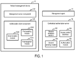
FIG. 1 is a block diagram showing a communication system according to an embodiment of the disclosure. The communication system may be part of a cloud/SDN environment such as the Internet of things (IoT). As shown, the communication system comprises anetwork management device 12, amanagement agent 14 and a centralizedauthorization server 16. Thenetwork management device 12 comprises amanagement server component 122 and anauthorization client component 124. Themanagement server component 122 is configured, with NETCONF protocol, to process a user operation request from themanagement agent 14 based at least on authorization information from theauthorization client component 124. Correspondingly, themanagement agent 14 is configured, with NETCONF protocol, to send the user operation request to and receive the operation result from themanagement server component 122. - The
authorization client component 124 is configured, with a remote authorization protocol, to obtain, for the user operation request, the authorization information from thecentralized authorization server 16. Correspondingly, thecentralized authorization server 16 is configured, with the same remote authorization protocol, to generate an authorization response for theauthorization client component 124. As an example, the remote authorization protocol may be terminal access controller access-control system plus (TACACS+) protocol, which can provide an extensible architecture of doing authorization. Alternatively, any other suitable remote authorization protocols such as remote authentication dial in user service (RADIUS) protocol may be employed. - In this way, the above solution can provide a way to do NETCONF centralized authorization. In turn, it can provide the possibility of doing centralized access-right control for a group of network management devices within the control of this solution. As an exemplary example, in the IoT case, the
network management device 12 may be a gateway for access to a home network. Themanagement agent 14 may be embedded in a terminal device or may be a terminal device itself, such as a mobile phone, a pad computer, a laptop computer, a desktop computer, or any other devices (e.g., a vehicle) with wired and/or wireless communication capability. Thecentralized authorization server 16 may be a remote server serving a plurality of the gateways located at different positions. This can easily provide the integrated authorization information without requiring the gateways in different positions to have the same authorization configuration. As another exemplary example, thenetwork management device 12 may be a gateway for access to the Internet of vehicles (IoV). Themanagement agent 14 may be embedded in a vehicle or may be a vehicle itself. Thecentralized authorization server 16 may be a remote server serving a plurality of the gateways located at different positions. In this case, the authorization response may be generated for a vehicle according to the vehicle's location. - As shown, the
authorization client component 124 may comprise afirst sending module 1242, afirst reception module 1244 and adetermination module 1246. Thecentralized authorization server 16 may comprise asecond reception module 162, anaccess control database 164, anauthorization module 166 and asecond sending module 168. The implementing details of the above constituent parts of the communication system will be described in detail with reference toFIG. 2 . -
FIG. 2 is a flowchart illustrating a process according to an embodiment of the disclosure. Although the process is described in the context of the IoT, those skilled in the art will understand that the principle of the present disclosure may also be applied to any other scenarios in which centralized authorization is needed for NETCONF. - At block 202, a user starts a session via the
management agent 14. As described above, themanagement agent 14 is a NETCONF agent which may be embedded in a terminal device. The user may operate the terminal device to trigger the start of the session. The session may be a secure shell (SSH) session. It may be started by sending an initial transmission control protocol (TCP) connection request from themanagement agent 14 to themanagement server component 122. - At
block 204, the session is established between themanagement agent 14 and themanagement server component 122. Specifically, in response to the initial TCP connection request, themanagement server component 122 may negotiate the SSH protocol version and exchange keys for message integrity and encryption with themanagement agent 14. Then, themanagement agent 14 may send an authentication request to themanagement server component 122. Various authentication protocols such as RADIUS protocol may be used to authenticate the user. Once the user has been successfully authenticated, themanagement agent 14 may send a session request to themanagement server component 122 such that the SSH session is established. - At
block 206, the user sends an operation request to themanagement server component 122 via themanagement agent 14. The operation request may be sent via remote procedure call (RPC). The operation request is expressed in extensible markup language (XML) and may indicate one or more operations. - In response to the operation request, transaction processing is started. Specifically, at
block 208, themanagement server component 122 converts the operation request to an operation identification and an Xpath. This may be achieved by a conversion from XML to Xpath. The operation identification may be the name of an executive program for performing an operation, such as "get-config", "edit-config" or the like as defined in NETCONF. The Xpath may represent an object on which the operation is to be performed. Since there may be one or more operations indicated in the operation request, one or more pairs of operation identifications and Xpaths may be obtained. - At
block 210, themanagement server component 122 passes the one or more pairs of operation identifications and Xpaths to theauthorization client component 124. Atblock 212, the authorization client component 124 (specifically, the first sending module 1242) sends to the centralized authorization server 16 (specifically, the second reception module 162) an authorization request including the one or more pairs of operation identifications and Xpaths. The authorization request further comprises an identification of the user, such as user name, group name or the like, which may be determined during the authentication performed atblock 204. For example, each pair of operation identification and Xpath may be set as two arguments in the Authorization_REQUEST message in the case where TACACS+ protocol is used. - In response to the authorization request, the centralized authorization server 16 (specifically, the
authorization module 166 together with the access control database 164) generates one or more authorization responses atblock 214. Theaccess control database 164 is configured to store information about identifications and access rights of a plurality of users. The information about an access right of a user may include: an operation identification; an Xpath representing an object on which the operation is to be performed; and access control information for determining whether the user is permitted to perform the operation. The access control information may include an access control rule for specifying whether a user name or a group name has an access right for particular operation(s). - As an exemplary example, a model for the
access control database 164 may be represented as follows:
- In the IoT case such as home-appliance access control scenario, the above model may be specifically represented as follows:


- The
authorization module 166 is configured to generate an authorization response for the authorization request based on theaccess control database 164. For example, the corresponding access control rule(s) may be located from theaccess control database 164 according to the user identification and be processed to determine the authorization response. In the above instance of home-appliance access control, if the user name is "child" and the requested operation is "read"+"/home/appliance/", then the rule "user-rule-2" may be located and processed such that the authorization response is determined as success. - It should be noted that the present disclosure is not limited to the above examples. Any features related to the access control as defined in NETCONF protocols such as RFC6536 may be employed in the
access control database 164 and theauthorization module 166. In this way, new authorization attributes containing, for example, the NETCONF Xpath and the corresponding access-right are introduced into the remote authorization protocol between theauthorization client component 124 and thecentralized authorization server 16. - At
block 216, the centralized authorization server 16 (specifically, the second sending module 168) sends the generated authorization response to the authorization client component 124 (specifically, the first reception module 1244). For example, the authorization response may be set into the status field of the Authorization_RESPONSE message in the case where TACACS+ protocol is used. Note that in the case where multiple operations are indicated in the operation request, blocks 212, 214 and 216 may be performed iteratively for each of the multiple operations. - At
block 218, the authorization client component 124 (specifically, the determination module 1246) determines the authorization information based on the one or more authorization responses. For example, in the case where multiple operations are indicated in the operation request, the authorization information may be determined as failure if the authorization response for any operation indicates failure, and may be determined as success if the authorization responses for all the operations indicate success. Atblock 220, the authorization client component 124 (specifically, the determination module 1246) passes the authorization information to themanagement server component 122. - At
block 222, themanagement server component 122 generates the operation result according to the authorization information. If the authorization information indicates failure, the result may be generated to indicate failure. On the other hand, if the authorization information indicates success, the executive program(s) may be run by means of a YANG base database to perform the one or more operations. Atblock 224, the result is returned from themanagement server component 122 to themanagement agent 14. -
FIG. 3 is a flowchart illustrating a method at a network management device according to an embodiment of the disclosure. Atblock 302, the network management device processes a user operation request from a management agent through NETCONF protocol. Atblock 304, the network management device obtains, for the user operation request, authorization information from a centralized authorization server through a remote authorization protocol. The processing of the user operation request atblock 302 is based at least on the authorization information. -
FIG. 4 is a flowchart for explaining the method shown inFIG. 3 . For example, block 302 may be implemented asblocks 406 and 412-418 shown inFIG. 4 .Block 304 may be implemented asblocks 408 and 410 shown inFIG. 4 . Atblock 406, the user operation request is converted to an operation identification and an Xpath. The Xpath represents an object on which the operation is to be performed.Block 406 may correspond to block 208 shown inFIG. 2 . - At block 408, an authorization request including the operation identification and the Xpath is sent to the centralized authorization server. Block 408 may correspond to block 212 shown in
FIG. 2 . Atblock 410, an authorization response is received from the centralized authorization server.Block 410 may correspond to block 216 shown inFIG. 2 . - At
block 412, the authorization information is determined based on the authorization response.Block 412 may correspond to block 218 shown inFIG. 2 . Atblock 414, a failure message is returned to the management agent when the authorization information indicates failure. On the other hand, atblock 416, operation(s) are performed according to the user operation request when the authorization information indicates success. Atblock 418, the operation result is returned to the management agent. Blocks 414-418 may correspond toblocks FIG. 2 . -
FIG. 5 is a flowchart illustrating a method at a centralized authorization server according to an embodiment of the disclosure. The centralized authorization server is configured with a remote authorization protocol. Atblock 502, a user authorization request is received from at least one of a plurality of network management devices configured with NETCONF protocol and located at different positions.Block 502 may correspond to block 212 shown inFIG. 2 . - At
block 504, an authorization response is generated for the user authorization request based on an access control database. The access control database is configured to store information about identifications and access rights of a plurality of users.Block 504 may correspond to block 214 shown inFIG. 2 . Atblock 506, the authorization response is sent to the at least one of the plurality of network management devices.Block 506 may correspond to block 216 shown inFIG. 2 . It should be noted that two steps shown in succession may, in fact, be executed substantially concurrently, or the steps may sometimes be executed in the reverse order, depending upon the functionality involved. -
FIG. 6 is a flowchart illustrating a method at a terminal device in a communication system according to an embodiment of the disclosure. The communication system further comprises a network management device and a centralized authorization server, as shown inFIG. 2 . Atblock 602, a user operation request is sent to the network management device through NETCONF protocol.Block 602 may correspond to block 206 shown inFIG. 2 . As described above, the network management device is configured to process the user operation request through NETCONF protocol, and to obtain, for the user operation request, authorization information from the centralized authorization server through a remote authorization protocol. Processing the user operation request is based at least on the authorization information such that an operation result or a failure message is generated. Atblock 604, the operation result or the failure message is received from the network management device.Block 604 may correspond to block 224 shown inFIG. 2 . -
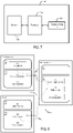
FIG. 7 is a block diagram showing an apparatus suitable for use in practicing some embodiments of the disclosure. For example, any one of the terminal device (embedded with the management agent 14), thenetwork management device 12 and thecentralized authorization server 16 may be implemented through theapparatus 700. As shown, theapparatus 700 may include aprocessor 710, amemory 720 that stores a program, and acommunication interface 730 for communicating data with other external devices through wired and/or wireless communication. - The program is assumed to include program instructions that, when executed by the
processor 710, enable theapparatus 700 to operate in accordance with the embodiments of the present disclosure, as discussed above. That is, the embodiments of the present disclosure may be implemented at least in part by computer software executable by theprocessor 710, or by hardware, or by a combination of software and hardware. - The
memory 720 may be of any type suitable to the local technical environment and may be implemented using any suitable data storage technology, such as semiconductor based memory devices, flash memory, magnetic memory devices and systems, optical memory devices and systems, fixed memory and removable memory. Theprocessor 710 may be of any type suitable to the local technical environment, and may include one or more of general purpose computers, special purpose computers, microprocessors, digital signal processors (DSPs) and processors based on multi-core processor architectures, as non-limiting examples. -
FIG. 8 is a block diagram showing a communication system suitable for use in practicing some embodiments of the disclosure. In this example, the terminal device is implemented as a user equipment (UE) which can communicate, via at least a cellular base station, with the network management device which is implemented as a host computer. Similar to the network management device, the centralized authorization server may also be implemented as a host computer. Note that the centralized authorization server is omitted incommunication system 800 ofFIG. 8 for brevity. - In other words, the present disclosure provides a communication system which comprises a UE, a base station, a first host computer and a second host computer. The first host computer includes a first processing circuitry and a first communication interface which are configured to act as the network management device. The second host computer includes a second processing circuitry and a second communication interface which are configured to act as the centralized authorization server. The first communication interface is configured to communicate with a cellular network. The cellular network comprises the base station having a radio interface and a third processing circuitry. The third processing circuitry is configured to transfer a user operation request from the UE to the first host computer and transfer an operation result or a failure message from the first host computer to the UE.
- Specifically, in
communication system 800,host computer 810 compriseshardware 815 includingcommunication interface 816 configured to set up and maintain a wired or wireless connection with an interface of a different communication device ofcommunication system 800.Host computer 810 further comprisesprocessing circuitry 818, which may have storage and/or processing capabilities. In particular, processingcircuitry 818 may comprise one or more programmable processors, application-specific integrated circuits, field programmable gate arrays or combinations of these (not shown) adapted to execute instructions.Host computer 810 further comprisessoftware 811, which is stored in or accessible byhost computer 810 and executable by processingcircuitry 818.Software 811 includeshost application 812.Host application 812 may be operable to provide a service to a remote user, such asUE 830 connecting viaconnection 850 terminating atUE 830 andhost computer 810. In providing the service to the remote user,host application 812 may provide user data which is transmitted usingconnection 850. -
Communication system 800 further includesbase station 820 provided in a telecommunication system and comprisinghardware 825 enabling it to communicate withhost computer 810 and withUE 830.Hardware 825 may includecommunication interface 826 for setting up and maintaining a wired or wireless connection with an interface of a different communication device ofcommunication system 800, as well asradio interface 827 for setting up and maintaining at least wireless connection 870 withUE 830 located in a coverage area (not shown inFigure 8 ) served bybase station 820.Communication interface 826 may be configured to facilitate connection 860 tohost computer 810. Connection 860 may be direct or it may pass through a core network (not shown inFigure 8 ) of the telecommunication system and/or through one or more intermediate networks outside the telecommunication system. In the embodiment shown,hardware 825 ofbase station 820 further includesprocessing circuitry 828, which may comprise one or more programmable processors, application-specific integrated circuits, field programmable gate arrays or combinations of these (not shown) adapted to execute instructions.Base station 820 further hassoftware 821 stored internally or accessible via an external connection. -
Communication system 800 further includesUE 830 already referred to. Itshardware 835 may includeradio interface 837 configured to set up and maintain wireless connection 870 with a base station serving a coverage area in whichUE 830 is currently located.Hardware 835 ofUE 830 further includesprocessing circuitry 838, which may comprise one or more programmable processors, application-specific integrated circuits, field programmable gate arrays or combinations of these (not shown) adapted to execute instructions.UE 830 further comprisessoftware 831, which is stored in or accessible byUE 830 and executable by processingcircuitry 838.Software 831 includesclient application 832.Client application 832 may be operable to provide a service to a human or non-human user viaUE 830, with the support ofhost computer 810. Inhost computer 810, an executinghost application 812 may communicate with the executingclient application 832 viaconnection 850 terminating atUE 830 andhost computer 810. In providing the service to the user,client application 832 may receive request data fromhost application 812 and provide user data in response to the request data.Connection 850 may transfer both the request data and the user data.Client application 832 may interact with the user to generate the user data that it provides. - In
FIG. 8 ,connection 850 has been drawn abstractly to illustrate the communication betweenhost computer 810 andUE 830 viabase station 820, without explicit reference to any intermediary devices and the precise routing of messages via these devices. Network infrastructure may determine the routing, which it may be configured to hide fromUE 830 or from the service provider operatinghost computer 810, or both. Whileconnection 850 is active, the network infrastructure may further take decisions by which it dynamically changes the routing (e.g., on the basis of load balancing consideration or reconfiguration of the network). - In general, the various exemplary embodiments may be implemented in hardware or special purpose circuits, software, logic or any combination thereof. For example, some aspects may be implemented in hardware, while other aspects may be implemented in firmware or software which may be executed by a controller, microprocessor or other computing device, although the disclosure is not limited thereto. While various aspects of the exemplary embodiments of this disclosure may be illustrated and described as block diagrams, flow charts, or using some other pictorial representation, it is well understood that these blocks, apparatus, systems, techniques or methods described herein may be implemented in, as non-limiting examples, hardware, software, firmware, special purpose circuits or logic, general purpose hardware or controller or other computing devices, or some combination thereof.
- As such, it should be appreciated that at least some aspects of the exemplary embodiments of the disclosure may be practiced in various components such as integrated circuit chips and modules. It should thus be appreciated that the exemplary embodiments of this disclosure may be realized in an apparatus that is embodied as an integrated circuit, where the integrated circuit may comprise circuitry (as well as possibly firmware) for embodying at least one or more of a data processor, a digital signal processor, baseband circuitry and radio frequency circuitry that are configurable so as to operate in accordance with the exemplary embodiments of this disclosure.
- It should be appreciated that at least some aspects of the exemplary embodiments of the disclosure may be embodied in computer-executable instructions, such as in one or more program modules, executed by one or more computers or other devices. Generally, program modules include routines, programs, objects, components, data structures, etc. that perform particular tasks or implement particular abstract data types when executed by a processor in a computer or other device. The computer executable instructions may be stored on a computer readable medium such as a hard disk, optical disk, removable storage media, solid state memory, RAM, etc. As will be appreciated by one of skill in the art, the function of the program modules may be combined or distributed as desired in various embodiments. In addition, the function may be embodied in whole or in part in firmware or hardware equivalents such as integrated circuits, field programmable gate arrays (FPGA), and the like.
- References in the present disclosure to "one embodiment", "an embodiment" and so on, indicate that the embodiment described may include a particular feature, structure, or characteristic, but it is not necessary that every embodiment includes the particular feature, structure, or characteristic. Moreover, such phrases are not necessarily referring to the same embodiment. Further, when a particular feature, structure, or characteristic is described in connection with an embodiment, it is submitted that it is within the knowledge of one skilled in the art to effect such feature, structure, or characteristic in connection with other embodiments whether or not explicitly described.
- It should be understood that, although the terms "first", "second" and so on may be used herein to describe various elements, these elements should not be limited by these terms. These terms are only used to distinguish one element from another. For example, a first element could be termed a second element, and similarly, a second element could be termed a first element, without departing from the scope of the disclosure. As used herein, the term "and/or" includes any and all combinations of one or more of the associated listed terms.
- The terminology used herein is for the purpose of describing particular embodiments only and is not intended to limit the present disclosure. As used herein, the singular forms "a", "an" and "the" are intended to include the plural forms as well, unless the context clearly indicates otherwise. It will be further understood that the terms "comprises", "comprising", "has", "having", "includes" and/or "including", when used herein, specify the presence of stated features, elements, and/or components, but do not preclude the presence or addition of one or more other features, elements, components and/ or combinations thereof. The terms "connect", "connects", "connecting" and/or "connected" used herein cover the direct and/or indirect connection between two elements.
Claims (8)
- A network management device (12) comprising:a management server component (122) configured with network configuration NETCONF, protocol; andan authorization client component (124) configured with a remote authorization protocol; whereinthe management server component (122) is configured to:receive a user operation request from a management agent (14), wherein the operation request indicates one or more operations;convert the operation request to one or more pairs of operation identifications and Xpaths, wherein the Xpath represents an object on which the operation is to be performed; andsend the one or more pairs of operation identifications and Xpaths to the authorization client component (124); andthe authorization client component (124) is configured to:send an authorization request including the one or more pairs of operation identifications and Xpaths to a centralized authorization server (16);obtain, for the user operation request, an authorization information from the centralized authorization server (16);send the authorization information to the management server component (122); andthe management server component (122) is further configured to:generate an operation result according to the authorization information; andsend the operation result to the management agent (14).
- The network management device (12) according to claim 1, wherein the remote authorization protocol is terminal access controller access-control system plus TACACS+, protocol or remote authentication dial in user service, RADIUS, protocol.
- The network management device (12) according to claim 1 or 2, wherein the authorization client component (124) comprises:a first sending module (1242) configured to send to the centralized authorization server (16) the authorization request;a first reception module (1244) configured to receive an authorization response from the centralized authorization server (16); anda determination module (1246) configured to determine the authorization information based on the authorization response.
- The network management device (12) according to claim 3,wherein the first sending module (1242) and the first reception module (1244) operate iteratively for each of the multiple operations; andwherein the determination module (1246) is configured to determine the authorization information as failure when the authorization response for any operation indicates failure, and to determine the authorization information as success when the authorization responses for the multiple operations indicate success.
- The network management device (12) according to any of claims 1 to 4, wherein the management server component (122) is configured to return a failure message to the management agent (14) when the authorization information indicates failure, and to perform operation(s) according to the user operation request and return the operation result to the management agent (14) when the authorization information indicates success;
and/or
wherein the network management device (12) is used in one of a cloud environment, a software defined network SDN, environment, and the Internet of things , IoT. - A method at a network management device, the method comprising:receiving (302) a user operation request from a management agent through network configuration, NETCONF, protocol, wherein the operation request indicates one or more operations;converting the operation request to one or more pairs of operation identifications and Xpaths, wherein the Xpath represents an object on which the operation is to be performed;sending an authorization request including the one or more pairs of operation identifications and Xpaths to a centralized authorization server (16);obtaining (304), for the user operation request, authorization information from the centralized authorization server through a remote authorization protocol;generating an operation result according to the authorization information; andsending the operation result to the management agent.
- The method according to claim 6,wherein obtaining (304) the authorization information comprises:receiving (410) an authorization response from the centralized authorization server; anddetermining (412) the authorization information based on the authorization response;and, optionally:wherein there are multiple operations indicated in the user operation request;wherein the sending (408) of the authorization request and the receiving (410) of the authorization response are performed iteratively for each of the multiple operations; andwherein determining (412) the authorization information comprises:determining the authorization information as failure when the authorization response for any operation indicates failure; anddetermining the authorization information as success when the authorization responses for the multiple operations indicate success.
- The method according to any of claims 6 to 7, wherein sending the operation result to the management agent comprises:returning (414) a failure message to the management agent when the authorization information indicates failure;performing (416) operation(s) according to the user operation request when the authorization information indicates success; andreturning (418) the operation result to the management agent.
Applications Claiming Priority (1)
| Application Number | Priority Date | Filing Date | Title |
|---|---|---|---|
| PCT/CN2017/114458 WO2019109210A1 (en) | 2017-12-04 | 2017-12-04 | Network management device and centralized authorization server for netconf |
Publications (3)
| Publication Number | Publication Date |
|---|---|
| EP3721596A1 EP3721596A1 (en) | 2020-10-14 |
| EP3721596A4 EP3721596A4 (en) | 2021-04-14 |
| EP3721596B1 true EP3721596B1 (en) | 2022-11-02 |
Family
ID=66750704
Family Applications (1)
| Application Number | Title | Priority Date | Filing Date |
|---|---|---|---|
| EP17933965.0A Active EP3721596B1 (en) | 2017-12-04 | 2017-12-04 | Network management device and centralized authorization server for netconf |
Country Status (4)
| Country | Link |
|---|---|
| US (1) | US20200389458A1 (en) |
| EP (1) | EP3721596B1 (en) |
| CN (1) | CN111434083B (en) |
| WO (1) | WO2019109210A1 (en) |
Families Citing this family (10)
| Publication number | Priority date | Publication date | Assignee | Title |
|---|---|---|---|---|
| CN112307486B (en) * | 2019-07-29 | 2024-06-18 | 华为技术有限公司 | Authority acquisition method, equipment and system |
| CN112235124B (en) * | 2020-08-14 | 2023-03-24 | 浙江三维利普维网络有限公司 | Method and device for configuring pico-cell, storage medium and electronic device |
| CN115589351B (en) * | 2021-07-06 | 2024-07-30 | 华为技术有限公司 | Query method, device and equipment |
| CN113472802B (en) * | 2021-07-13 | 2022-05-31 | 安徽睿极智能科技有限公司 | Distributed remote authorization method and system |
| CN114244712B (en) * | 2021-12-08 | 2023-12-05 | 中盈优创资讯科技有限公司 | SDN controller protocol state management method and device |
| CN115065523B (en) * | 2022-06-10 | 2024-06-18 | 联想(北京)有限公司 | Data processing method and device |
| CN115145443A (en) * | 2022-07-15 | 2022-10-04 | 中国银行股份有限公司 | Bank business authorization information configuration method and device |
| CN118120269A (en) * | 2022-09-30 | 2024-05-31 | 北京小米移动软件有限公司 | Application function authorization method and device |
| CN116661784B (en) * | 2023-06-01 | 2024-05-07 | 北京首都在线科技股份有限公司 | Page configuration method and electronic equipment |
| CN118474155B (en) * | 2024-07-11 | 2024-09-24 | 杭州行至云起科技有限公司 | Data processing method, device, storage medium and program product for industry application |
Family Cites Families (19)
| Publication number | Priority date | Publication date | Assignee | Title |
|---|---|---|---|---|
| US7882538B1 (en) | 2006-02-02 | 2011-02-01 | Juniper Networks, Inc. | Local caching of endpoint security information |
| JP4714111B2 (en) * | 2006-08-29 | 2011-06-29 | 株式会社日立製作所 | Management computer, computer system and switch |
| CN101237443B (en) * | 2007-02-01 | 2012-08-22 | 华为技术有限公司 | Method and system for user authentication in management protocol |
| CN101110822B (en) * | 2007-07-06 | 2011-11-02 | 华为技术有限公司 | Event notice sending method, system and equipment based on network configuration protocol |
| WO2009063555A1 (en) * | 2007-11-13 | 2009-05-22 | Fujitsu Limited | Control proxy device, control proxy method and control proxy program |
| US8296671B2 (en) * | 2008-05-01 | 2012-10-23 | Microsoft Corporation | Enabling access to rich data by intercepting paste operations |
| US8676999B2 (en) * | 2008-10-10 | 2014-03-18 | Futurewei Technologies, Inc. | System and method for remote authentication dial in user service (RADIUS) prefix authorization application |
| US8248958B1 (en) * | 2009-12-09 | 2012-08-21 | Juniper Networks, Inc. | Remote validation of network device configuration using a device management protocol for remote packet injection |
| KR101288233B1 (en) * | 2011-11-07 | 2013-07-26 | 엘에스산전 주식회사 | Access control apparatus and access controlling method in scada system |
| CN102368716A (en) * | 2011-11-29 | 2012-03-07 | 迈普通信技术股份有限公司 | Data acquisition method of network configuration protocol and network configuration server |
| CN102427409A (en) * | 2012-01-31 | 2012-04-25 | 迈普通信技术股份有限公司 | Configuration data submission method based on network configuration (NETCONF) protocol and server thereof |
| US20120266209A1 (en) * | 2012-06-11 | 2012-10-18 | David Jeffrey Gooding | Method of Secure Electric Power Grid Operations Using Common Cyber Security Services |
| US11388082B2 (en) * | 2013-11-27 | 2022-07-12 | Oracle International Corporation | Methods, systems, and computer readable media for diameter routing using software defined network (SDN) functionality |
| CN105337852B (en) * | 2014-07-03 | 2019-11-05 | 华为技术有限公司 | The more method and device of the processing mode of new service flow message |
| CN106161077B (en) * | 2015-04-24 | 2019-07-09 | 中兴通讯股份有限公司 | Cut-in convergent device and certification register method |
| EP3387550B1 (en) * | 2015-12-10 | 2020-12-02 | Microsoft Technology Licensing, LLC | Data driven automated provisioning of telecommunication applications |
| CN106454823A (en) * | 2016-08-12 | 2017-02-22 | 中国南方电网有限责任公司 | Authentication method for network security access and authentication system for implementing method |
| US11190510B2 (en) * | 2017-11-15 | 2021-11-30 | Parallel Wireless, Inc. | Two-factor authentication in a cellular radio access network |
| CN118400267A (en) * | 2019-02-08 | 2024-07-26 | 微软技术许可有限责任公司 | Computing device and method for model-driven service rollback |
-
2017
- 2017-12-04 EP EP17933965.0A patent/EP3721596B1/en active Active
- 2017-12-04 CN CN201780097377.5A patent/CN111434083B/en active Active
- 2017-12-04 US US16/764,054 patent/US20200389458A1/en not_active Abandoned
- 2017-12-04 WO PCT/CN2017/114458 patent/WO2019109210A1/en unknown
Also Published As
| Publication number | Publication date |
|---|---|
| WO2019109210A1 (en) | 2019-06-13 |
| CN111434083B (en) | 2022-11-22 |
| CN111434083A (en) | 2020-07-17 |
| EP3721596A1 (en) | 2020-10-14 |
| EP3721596A4 (en) | 2021-04-14 |
| US20200389458A1 (en) | 2020-12-10 |
Similar Documents
| Publication | Publication Date | Title |
|---|---|---|
| EP3721596B1 (en) | Network management device and centralized authorization server for netconf | |
| WO2019220172A1 (en) | Token-based debugging for a service-based architecture | |
| CN113302960B (en) | Method for authentication and key management in a wireless communication network and related apparatus | |
| CN112913212A (en) | Control of user plane functions with control plane-user plane separation | |
| JP2022509188A (en) | User access control method, information transmission method and device | |
| EP3713372A1 (en) | Method and device for creating user group | |
| WO2018232253A1 (en) | Network exposure function | |
| US20240171647A1 (en) | Method and apparatus for discovering edge application server | |
| EP3984306B1 (en) | Methods and apparatuses for logical tsn bridge | |
| US20230099786A1 (en) | Methods and Apparatus for Provisioning Private Network Devices During Onboarding | |
| EP3860176B1 (en) | Method, apparatus, and system for obtaining capability information of terminal | |
| US20240244495A1 (en) | Communication method | |
| WO2020248579A1 (en) | Method and apparatus for allocating pdu session id for terminal device | |
| TW202119855A (en) | Base station and data transmission method thereof for mobile communication system | |
| US20230137034A1 (en) | Method for token-based authorization for indirect communication between network functions | |
| US12101838B2 (en) | Communications method, apparatus, and system | |
| WO2022199411A1 (en) | Method and apparatus for providing configuration for serving terminal device | |
| US12075496B2 (en) | Method and apparatus for network function managing NIDD session | |
| JP7437537B2 (en) | Application function nodes, access and mobility management function nodes, systems and methods in communication networks | |
| WO2023070340A1 (en) | Network repository function policy control for different public land mobile networks | |
| US20240314557A1 (en) | Network repository function services access authorization | |
| EP4436112A1 (en) | Communication method and apparatus | |
| US20240155325A1 (en) | Information obtaining method and apparatus, and system | |
| WO2021031904A1 (en) | Method and entity for transmitting a plurality of mac addresses | |
| WO2020187184A1 (en) | Method and apparatus for obtaining network slice information |
Legal Events
| Date | Code | Title | Description |
|---|---|---|---|
| STAA | Information on the status of an ep patent application or granted ep patent |
Free format text: STATUS: THE INTERNATIONAL PUBLICATION HAS BEEN MADE |
|
| PUAI | Public reference made under article 153(3) epc to a published international application that has entered the european phase |
Free format text: ORIGINAL CODE: 0009012 |
|
| STAA | Information on the status of an ep patent application or granted ep patent |
Free format text: STATUS: REQUEST FOR EXAMINATION WAS MADE |
|
| 17P | Request for examination filed |
Effective date: 20200612 |
|
| AK | Designated contracting states |
Kind code of ref document: A1 Designated state(s): AL AT BE BG CH CY CZ DE DK EE ES FI FR GB GR HR HU IE IS IT LI LT LU LV MC MK MT NL NO PL PT RO RS SE SI SK SM TR |
|
| AX | Request for extension of the european patent |
Extension state: BA ME |
|
| DAV | Request for validation of the european patent (deleted) | ||
| DAX | Request for extension of the european patent (deleted) | ||
| A4 | Supplementary search report drawn up and despatched |
Effective date: 20210312 |
|
| RIC1 | Information provided on ipc code assigned before grant |
Ipc: H04L 29/06 20060101AFI20210305BHEP Ipc: H04L 12/24 20060101ALI20210305BHEP |
|
| REG | Reference to a national code |
Ref country code: DE Ref legal event code: R079 Ref document number: 602017063426 Country of ref document: DE Free format text: PREVIOUS MAIN CLASS: H04L0029060000 Ipc: H04L0009400000 |
|
| GRAP | Despatch of communication of intention to grant a patent |
Free format text: ORIGINAL CODE: EPIDOSNIGR1 |
|
| RIC1 | Information provided on ipc code assigned before grant |
Ipc: H04L 41/28 20220101ALI20220516BHEP Ipc: H04L 9/40 20220101AFI20220516BHEP |
|
| STAA | Information on the status of an ep patent application or granted ep patent |
Free format text: STATUS: GRANT OF PATENT IS INTENDED |
|
| INTG | Intention to grant announced |
Effective date: 20220623 |
|
| GRAS | Grant fee paid |
Free format text: ORIGINAL CODE: EPIDOSNIGR3 |
|
| GRAA | (expected) grant |
Free format text: ORIGINAL CODE: 0009210 |
|
| STAA | Information on the status of an ep patent application or granted ep patent |
Free format text: STATUS: THE PATENT HAS BEEN GRANTED |
|
| AK | Designated contracting states |
Kind code of ref document: B1 Designated state(s): AL AT BE BG CH CY CZ DE DK EE ES FI FR GB GR HR HU IE IS IT LI LT LU LV MC MK MT NL NO PL PT RO RS SE SI SK SM TR |
|
| REG | Reference to a national code |
Ref country code: GB Ref legal event code: FG4D |
|
| REG | Reference to a national code |
Ref country code: CH Ref legal event code: EP Ref country code: AT Ref legal event code: REF Ref document number: 1529584 Country of ref document: AT Kind code of ref document: T Effective date: 20221115 |
|
| REG | Reference to a national code |
Ref country code: DE Ref legal event code: R096 Ref document number: 602017063426 Country of ref document: DE |
|
| REG | Reference to a national code |
Ref country code: IE Ref legal event code: FG4D |
|
| REG | Reference to a national code |
Ref country code: LT Ref legal event code: MG9D |
|
| REG | Reference to a national code |
Ref country code: NL Ref legal event code: MP Effective date: 20221102 |
|
| REG | Reference to a national code |
Ref country code: AT Ref legal event code: MK05 Ref document number: 1529584 Country of ref document: AT Kind code of ref document: T Effective date: 20221102 |
|
| PG25 | Lapsed in a contracting state [announced via postgrant information from national office to epo] |
Ref country code: SE Free format text: LAPSE BECAUSE OF FAILURE TO SUBMIT A TRANSLATION OF THE DESCRIPTION OR TO PAY THE FEE WITHIN THE PRESCRIBED TIME-LIMIT Effective date: 20221102 Ref country code: PT Free format text: LAPSE BECAUSE OF FAILURE TO SUBMIT A TRANSLATION OF THE DESCRIPTION OR TO PAY THE FEE WITHIN THE PRESCRIBED TIME-LIMIT Effective date: 20230302 Ref country code: NO Free format text: LAPSE BECAUSE OF FAILURE TO SUBMIT A TRANSLATION OF THE DESCRIPTION OR TO PAY THE FEE WITHIN THE PRESCRIBED TIME-LIMIT Effective date: 20230202 Ref country code: LT Free format text: LAPSE BECAUSE OF FAILURE TO SUBMIT A TRANSLATION OF THE DESCRIPTION OR TO PAY THE FEE WITHIN THE PRESCRIBED TIME-LIMIT Effective date: 20221102 Ref country code: FI Free format text: LAPSE BECAUSE OF FAILURE TO SUBMIT A TRANSLATION OF THE DESCRIPTION OR TO PAY THE FEE WITHIN THE PRESCRIBED TIME-LIMIT Effective date: 20221102 Ref country code: ES Free format text: LAPSE BECAUSE OF FAILURE TO SUBMIT A TRANSLATION OF THE DESCRIPTION OR TO PAY THE FEE WITHIN THE PRESCRIBED TIME-LIMIT Effective date: 20221102 Ref country code: AT Free format text: LAPSE BECAUSE OF FAILURE TO SUBMIT A TRANSLATION OF THE DESCRIPTION OR TO PAY THE FEE WITHIN THE PRESCRIBED TIME-LIMIT Effective date: 20221102 |
|
| PG25 | Lapsed in a contracting state [announced via postgrant information from national office to epo] |
Ref country code: RS Free format text: LAPSE BECAUSE OF FAILURE TO SUBMIT A TRANSLATION OF THE DESCRIPTION OR TO PAY THE FEE WITHIN THE PRESCRIBED TIME-LIMIT Effective date: 20221102 Ref country code: PL Free format text: LAPSE BECAUSE OF FAILURE TO SUBMIT A TRANSLATION OF THE DESCRIPTION OR TO PAY THE FEE WITHIN THE PRESCRIBED TIME-LIMIT Effective date: 20221102 Ref country code: LV Free format text: LAPSE BECAUSE OF FAILURE TO SUBMIT A TRANSLATION OF THE DESCRIPTION OR TO PAY THE FEE WITHIN THE PRESCRIBED TIME-LIMIT Effective date: 20221102 Ref country code: IS Free format text: LAPSE BECAUSE OF FAILURE TO SUBMIT A TRANSLATION OF THE DESCRIPTION OR TO PAY THE FEE WITHIN THE PRESCRIBED TIME-LIMIT Effective date: 20230302 Ref country code: HR Free format text: LAPSE BECAUSE OF FAILURE TO SUBMIT A TRANSLATION OF THE DESCRIPTION OR TO PAY THE FEE WITHIN THE PRESCRIBED TIME-LIMIT Effective date: 20221102 Ref country code: GR Free format text: LAPSE BECAUSE OF FAILURE TO SUBMIT A TRANSLATION OF THE DESCRIPTION OR TO PAY THE FEE WITHIN THE PRESCRIBED TIME-LIMIT Effective date: 20230203 |
|
| PG25 | Lapsed in a contracting state [announced via postgrant information from national office to epo] |
Ref country code: NL Free format text: LAPSE BECAUSE OF FAILURE TO SUBMIT A TRANSLATION OF THE DESCRIPTION OR TO PAY THE FEE WITHIN THE PRESCRIBED TIME-LIMIT Effective date: 20221102 |
|
| PG25 | Lapsed in a contracting state [announced via postgrant information from national office to epo] |
Ref country code: SM Free format text: LAPSE BECAUSE OF FAILURE TO SUBMIT A TRANSLATION OF THE DESCRIPTION OR TO PAY THE FEE WITHIN THE PRESCRIBED TIME-LIMIT Effective date: 20221102 Ref country code: RO Free format text: LAPSE BECAUSE OF FAILURE TO SUBMIT A TRANSLATION OF THE DESCRIPTION OR TO PAY THE FEE WITHIN THE PRESCRIBED TIME-LIMIT Effective date: 20221102 Ref country code: EE Free format text: LAPSE BECAUSE OF FAILURE TO SUBMIT A TRANSLATION OF THE DESCRIPTION OR TO PAY THE FEE WITHIN THE PRESCRIBED TIME-LIMIT Effective date: 20221102 Ref country code: DK Free format text: LAPSE BECAUSE OF FAILURE TO SUBMIT A TRANSLATION OF THE DESCRIPTION OR TO PAY THE FEE WITHIN THE PRESCRIBED TIME-LIMIT Effective date: 20221102 Ref country code: CZ Free format text: LAPSE BECAUSE OF FAILURE TO SUBMIT A TRANSLATION OF THE DESCRIPTION OR TO PAY THE FEE WITHIN THE PRESCRIBED TIME-LIMIT Effective date: 20221102 |
|
| REG | Reference to a national code |
Ref country code: CH Ref legal event code: PL |
|
| REG | Reference to a national code |
Ref country code: DE Ref legal event code: R097 Ref document number: 602017063426 Country of ref document: DE |
|
| REG | Reference to a national code |
Ref country code: BE Ref legal event code: MM Effective date: 20221231 |
|
| PG25 | Lapsed in a contracting state [announced via postgrant information from national office to epo] |
Ref country code: SK Free format text: LAPSE BECAUSE OF FAILURE TO SUBMIT A TRANSLATION OF THE DESCRIPTION OR TO PAY THE FEE WITHIN THE PRESCRIBED TIME-LIMIT Effective date: 20221102 Ref country code: LU Free format text: LAPSE BECAUSE OF NON-PAYMENT OF DUE FEES Effective date: 20221204 Ref country code: AL Free format text: LAPSE BECAUSE OF FAILURE TO SUBMIT A TRANSLATION OF THE DESCRIPTION OR TO PAY THE FEE WITHIN THE PRESCRIBED TIME-LIMIT Effective date: 20221102 |
|
| PLBE | No opposition filed within time limit |
Free format text: ORIGINAL CODE: 0009261 |
|
| STAA | Information on the status of an ep patent application or granted ep patent |
Free format text: STATUS: NO OPPOSITION FILED WITHIN TIME LIMIT |
|
| 26N | No opposition filed |
Effective date: 20230803 |
|
| PG25 | Lapsed in a contracting state [announced via postgrant information from national office to epo] |
Ref country code: LI Free format text: LAPSE BECAUSE OF NON-PAYMENT OF DUE FEES Effective date: 20221231 Ref country code: IE Free format text: LAPSE BECAUSE OF NON-PAYMENT OF DUE FEES Effective date: 20221204 Ref country code: CH Free format text: LAPSE BECAUSE OF NON-PAYMENT OF DUE FEES Effective date: 20221231 |
|
| PG25 | Lapsed in a contracting state [announced via postgrant information from national office to epo] |
Ref country code: SI Free format text: LAPSE BECAUSE OF FAILURE TO SUBMIT A TRANSLATION OF THE DESCRIPTION OR TO PAY THE FEE WITHIN THE PRESCRIBED TIME-LIMIT Effective date: 20221102 Ref country code: FR Free format text: LAPSE BECAUSE OF NON-PAYMENT OF DUE FEES Effective date: 20230102 Ref country code: BE Free format text: LAPSE BECAUSE OF NON-PAYMENT OF DUE FEES Effective date: 20221231 |
|
| PGFP | Annual fee paid to national office [announced via postgrant information from national office to epo] |
Ref country code: GB Payment date: 20231227 Year of fee payment: 7 |
|
| PG25 | Lapsed in a contracting state [announced via postgrant information from national office to epo] |
Ref country code: CY Free format text: LAPSE BECAUSE OF FAILURE TO SUBMIT A TRANSLATION OF THE DESCRIPTION OR TO PAY THE FEE WITHIN THE PRESCRIBED TIME-LIMIT Effective date: 20221102 |
|
| PGFP | Annual fee paid to national office [announced via postgrant information from national office to epo] |
Ref country code: DE Payment date: 20231229 Year of fee payment: 7 |
|
| PG25 | Lapsed in a contracting state [announced via postgrant information from national office to epo] |
Ref country code: MK Free format text: LAPSE BECAUSE OF FAILURE TO SUBMIT A TRANSLATION OF THE DESCRIPTION OR TO PAY THE FEE WITHIN THE PRESCRIBED TIME-LIMIT Effective date: 20221102 Ref country code: IT Free format text: LAPSE BECAUSE OF FAILURE TO SUBMIT A TRANSLATION OF THE DESCRIPTION OR TO PAY THE FEE WITHIN THE PRESCRIBED TIME-LIMIT Effective date: 20221102 Ref country code: HU Free format text: LAPSE BECAUSE OF FAILURE TO SUBMIT A TRANSLATION OF THE DESCRIPTION OR TO PAY THE FEE WITHIN THE PRESCRIBED TIME-LIMIT; INVALID AB INITIO Effective date: 20171204 |
|
| PG25 | Lapsed in a contracting state [announced via postgrant information from national office to epo] |
Ref country code: MC Free format text: LAPSE BECAUSE OF FAILURE TO SUBMIT A TRANSLATION OF THE DESCRIPTION OR TO PAY THE FEE WITHIN THE PRESCRIBED TIME-LIMIT Effective date: 20221102 |
|
| PG25 | Lapsed in a contracting state [announced via postgrant information from national office to epo] |
Ref country code: MC Free format text: LAPSE BECAUSE OF FAILURE TO SUBMIT A TRANSLATION OF THE DESCRIPTION OR TO PAY THE FEE WITHIN THE PRESCRIBED TIME-LIMIT Effective date: 20221102 |
|
| PG25 | Lapsed in a contracting state [announced via postgrant information from national office to epo] |
Ref country code: BG Free format text: LAPSE BECAUSE OF FAILURE TO SUBMIT A TRANSLATION OF THE DESCRIPTION OR TO PAY THE FEE WITHIN THE PRESCRIBED TIME-LIMIT Effective date: 20221102 |
|
| PG25 | Lapsed in a contracting state [announced via postgrant information from national office to epo] |
Ref country code: MT Free format text: LAPSE BECAUSE OF FAILURE TO SUBMIT A TRANSLATION OF THE DESCRIPTION OR TO PAY THE FEE WITHIN THE PRESCRIBED TIME-LIMIT Effective date: 20221102 |