EP3721144B1 - A modular pre-cooling system - Google Patents
A modular pre-cooling system Download PDFInfo
- Publication number
- EP3721144B1 EP3721144B1 EP18913594.0A EP18913594A EP3721144B1 EP 3721144 B1 EP3721144 B1 EP 3721144B1 EP 18913594 A EP18913594 A EP 18913594A EP 3721144 B1 EP3721144 B1 EP 3721144B1
- Authority
- EP
- European Patent Office
- Prior art keywords
- air
- water
- cooling system
- cooling
- nozzles
- Prior art date
- Legal status (The legal status is an assumption and is not a legal conclusion. Google has not performed a legal analysis and makes no representation as to the accuracy of the status listed.)
- Active
Links
- 238000001816 cooling Methods 0.000 title claims description 76
- 239000003570 air Substances 0.000 claims description 54
- XLYOFNOQVPJJNP-UHFFFAOYSA-N water Substances O XLYOFNOQVPJJNP-UHFFFAOYSA-N 0.000 claims description 42
- 230000007246 mechanism Effects 0.000 claims description 18
- 238000000034 method Methods 0.000 claims description 10
- 230000005540 biological transmission Effects 0.000 claims description 7
- 230000008569 process Effects 0.000 claims description 7
- VNWKTOKETHGBQD-UHFFFAOYSA-N methane Chemical compound C VNWKTOKETHGBQD-UHFFFAOYSA-N 0.000 claims description 6
- 238000005507 spraying Methods 0.000 claims description 6
- 238000004364 calculation method Methods 0.000 claims description 5
- 239000007921 spray Substances 0.000 claims description 5
- 239000012080 ambient air Substances 0.000 claims description 3
- 238000011109 contamination Methods 0.000 claims description 3
- 239000003345 natural gas Substances 0.000 claims description 3
- 239000003507 refrigerant Substances 0.000 claims description 3
- 230000002308 calcification Effects 0.000 claims description 2
- 239000000126 substance Substances 0.000 claims description 2
- 230000000694 effects Effects 0.000 description 5
- 239000000428 dust Substances 0.000 description 4
- 239000002245 particle Substances 0.000 description 4
- 230000006378 damage Effects 0.000 description 3
- 238000013461 design Methods 0.000 description 3
- 238000001704 evaporation Methods 0.000 description 3
- 238000009434 installation Methods 0.000 description 3
- 239000007788 liquid Substances 0.000 description 3
- 238000012423 maintenance Methods 0.000 description 3
- 238000004519 manufacturing process Methods 0.000 description 3
- 230000005611 electricity Effects 0.000 description 2
- 230000008020 evaporation Effects 0.000 description 2
- 239000012530 fluid Substances 0.000 description 2
- 239000007789 gas Substances 0.000 description 2
- 238000012546 transfer Methods 0.000 description 2
- 238000010792 warming Methods 0.000 description 2
- 241000283690 Bos taurus Species 0.000 description 1
- OKTJSMMVPCPJKN-UHFFFAOYSA-N Carbon Chemical compound [C] OKTJSMMVPCPJKN-UHFFFAOYSA-N 0.000 description 1
- RYGMFSIKBFXOCR-UHFFFAOYSA-N Copper Chemical compound [Cu] RYGMFSIKBFXOCR-UHFFFAOYSA-N 0.000 description 1
- 239000004677 Nylon Substances 0.000 description 1
- 230000009471 action Effects 0.000 description 1
- 229910052782 aluminium Inorganic materials 0.000 description 1
- XAGFODPZIPBFFR-UHFFFAOYSA-N aluminium Chemical compound [Al] XAGFODPZIPBFFR-UHFFFAOYSA-N 0.000 description 1
- 238000004458 analytical method Methods 0.000 description 1
- 230000015572 biosynthetic process Effects 0.000 description 1
- 229910052799 carbon Inorganic materials 0.000 description 1
- 230000006835 compression Effects 0.000 description 1
- 238000007906 compression Methods 0.000 description 1
- 229910052802 copper Inorganic materials 0.000 description 1
- 239000010949 copper Substances 0.000 description 1
- 238000005260 corrosion Methods 0.000 description 1
- 230000007797 corrosion Effects 0.000 description 1
- 235000013365 dairy product Nutrition 0.000 description 1
- 230000003247 decreasing effect Effects 0.000 description 1
- 238000011161 development Methods 0.000 description 1
- 238000011156 evaluation Methods 0.000 description 1
- 230000006872 improvement Effects 0.000 description 1
- 244000144972 livestock Species 0.000 description 1
- 239000000463 material Substances 0.000 description 1
- 229910052751 metal Inorganic materials 0.000 description 1
- 239000002184 metal Substances 0.000 description 1
- 229920001778 nylon Polymers 0.000 description 1
- 238000005192 partition Methods 0.000 description 1
- 244000144977 poultry Species 0.000 description 1
- 230000002265 prevention Effects 0.000 description 1
- 238000004064 recycling Methods 0.000 description 1
- 239000010802 sludge Substances 0.000 description 1
- 230000001629 suppression Effects 0.000 description 1
- 239000004753 textile Substances 0.000 description 1
- 239000002351 wastewater Substances 0.000 description 1
Images


Classifications
-
- F—MECHANICAL ENGINEERING; LIGHTING; HEATING; WEAPONS; BLASTING
- F24—HEATING; RANGES; VENTILATING
- F24F—AIR-CONDITIONING; AIR-HUMIDIFICATION; VENTILATION; USE OF AIR CURRENTS FOR SCREENING
- F24F5/00—Air-conditioning systems or apparatus not covered by F24F1/00 or F24F3/00, e.g. using solar heat or combined with household units such as an oven or water heater
- F24F5/0007—Air-conditioning systems or apparatus not covered by F24F1/00 or F24F3/00, e.g. using solar heat or combined with household units such as an oven or water heater cooling apparatus specially adapted for use in air-conditioning
- F24F5/0035—Air-conditioning systems or apparatus not covered by F24F1/00 or F24F3/00, e.g. using solar heat or combined with household units such as an oven or water heater cooling apparatus specially adapted for use in air-conditioning using evaporation
-
- F—MECHANICAL ENGINEERING; LIGHTING; HEATING; WEAPONS; BLASTING
- F24—HEATING; RANGES; VENTILATING
- F24F—AIR-CONDITIONING; AIR-HUMIDIFICATION; VENTILATION; USE OF AIR CURRENTS FOR SCREENING
- F24F6/00—Air-humidification, e.g. cooling by humidification
- F24F6/02—Air-humidification, e.g. cooling by humidification by evaporation of water in the air
- F24F6/06—Air-humidification, e.g. cooling by humidification by evaporation of water in the air using moving unheated wet elements
-
- F—MECHANICAL ENGINEERING; LIGHTING; HEATING; WEAPONS; BLASTING
- F24—HEATING; RANGES; VENTILATING
- F24F—AIR-CONDITIONING; AIR-HUMIDIFICATION; VENTILATION; USE OF AIR CURRENTS FOR SCREENING
- F24F6/00—Air-humidification, e.g. cooling by humidification
- F24F6/12—Air-humidification, e.g. cooling by humidification by forming water dispersions in the air
-
- F—MECHANICAL ENGINEERING; LIGHTING; HEATING; WEAPONS; BLASTING
- F24—HEATING; RANGES; VENTILATING
- F24F—AIR-CONDITIONING; AIR-HUMIDIFICATION; VENTILATION; USE OF AIR CURRENTS FOR SCREENING
- F24F1/00—Room units for air-conditioning, e.g. separate or self-contained units or units receiving primary air from a central station
- F24F1/06—Separate outdoor units, e.g. outdoor unit to be linked to a separate room comprising a compressor and a heat exchanger
- F24F1/42—Separate outdoor units, e.g. outdoor unit to be linked to a separate room comprising a compressor and a heat exchanger characterised by the use of the condensate, e.g. for enhanced cooling
-
- Y—GENERAL TAGGING OF NEW TECHNOLOGICAL DEVELOPMENTS; GENERAL TAGGING OF CROSS-SECTIONAL TECHNOLOGIES SPANNING OVER SEVERAL SECTIONS OF THE IPC; TECHNICAL SUBJECTS COVERED BY FORMER USPC CROSS-REFERENCE ART COLLECTIONS [XRACs] AND DIGESTS
- Y02—TECHNOLOGIES OR APPLICATIONS FOR MITIGATION OR ADAPTATION AGAINST CLIMATE CHANGE
- Y02B—CLIMATE CHANGE MITIGATION TECHNOLOGIES RELATED TO BUILDINGS, e.g. HOUSING, HOUSE APPLIANCES OR RELATED END-USER APPLICATIONS
- Y02B10/00—Integration of renewable energy sources in buildings
- Y02B10/40—Geothermal heat-pumps
-
- Y—GENERAL TAGGING OF NEW TECHNOLOGICAL DEVELOPMENTS; GENERAL TAGGING OF CROSS-SECTIONAL TECHNOLOGIES SPANNING OVER SEVERAL SECTIONS OF THE IPC; TECHNICAL SUBJECTS COVERED BY FORMER USPC CROSS-REFERENCE ART COLLECTIONS [XRACs] AND DIGESTS
- Y02—TECHNOLOGIES OR APPLICATIONS FOR MITIGATION OR ADAPTATION AGAINST CLIMATE CHANGE
- Y02B—CLIMATE CHANGE MITIGATION TECHNOLOGIES RELATED TO BUILDINGS, e.g. HOUSING, HOUSE APPLIANCES OR RELATED END-USER APPLICATIONS
- Y02B30/00—Energy efficient heating, ventilation or air conditioning [HVAC]
- Y02B30/54—Free-cooling systems
Definitions
- the invention relates to a modular pre-cooling system.
- the invention relates to a humidification-based (evaporative-adiabatic) modular cooling system which provides energy efficiency, reduces or eliminates filter and maintenance costs by cooling the intake air of the system when the ambient air temperature of the central air-cooled systems (Electricity generation systems, Gas & Steam Turbine power plants, Geothermal power plants, Cogeneration, Trigeneration systems with electricity consumption comfort and / or process cooling systems, Air-cooled Chiller, Dry Cooler, Roof-top, etc.) is higher than the ISO design conditions.
- the central air-cooled systems Electricity generation systems, Gas & Steam Turbine power plants, Geothermal power plants, Cogeneration, Trigeneration systems with electricity consumption comfort and / or process cooling systems, Air-cooled Chiller, Dry Cooler, Roof-top, etc.
- heat transfer coefficient of water Since heat transfer coefficient of water is high, it has high evaporation tendency and absorbs heat from its environment during evaporation. When the water comes into contact with air, it takes heat from the air to cool the air and thus increases the amount of water vapor in the air. In the logic of evaporative cooling, the air is brought into contact with the highest possible amount of water and thus cooling of the air is provided. Evaporative cooling is achieved by evaporating water in an air stream at ambient temperature. In this cooling method, cooling is achieved by decreasing the dry bulb temperature of the air at the fixed wet bulb temperature and by increasing the amount of moisture contained in the air. Although evaporative cooling can be achieved by direct contact of air with water, it can also be achieved indirectly or by combining both systems.
- direct evaporative cooling process air is passed through a water block. As a result of direct contact of air with water, the air is brought to the desired conditions due to mass and heat transfer.
- the most common dry-bulb temperature difference that can be achieved in this method is the difference between the dry and wet bulb temperatures of the incoming air.
- the efficiency of direct evaporative cooling systems varies between 85-90% and reduces cooling costs by 25-40% when used with vapor compression cooling systems.
- Direct evaporative cooling systems are frequently used in factories, manufacturing plants (especially for textiles), open spaces and livestock (dairy cattle and poultry) sectors because of their economical advantages.
- pads In this type of cooling process, water flow from the top of a pad filled with cavities is ensured, during the continuous movement of the mentioned water in the pad, hot air passes through the cavities in the pad and contacts with the water and thus cooling the air with the water is achieved.
- padded systems due to their nature, not only create a loss of pressure of 200-250 Pascal in the intake air of the systems to be applied, and occasionally the water particles detached from the pad can wet the condensers or serpentines, but also accelerate corrosion in copper tube serpentines with aluminum blade by creating a battery effect and formation of sludge that is hard to clean via the dust present in the air, so it can cause serious damage to the turbine blades.
- the invention relates to a cooling system connected to the air inlet of an air-cooled refrigerant comprising at least one frame, at least one mesh fixed to said frame so as to remain at a distance from the cooler, at least one liquid spraying element which exerts a non-cooling from the external side of the said mesh, which is opposite to the cooler, and in the direction of air supply, at least one fluid supply kit for delivering liquid to said element, and at least one liquid-conducting element carrying the liquid from the fluid supply kit to the spray element, and the invention relates to the cooling method in which this system is used.
- US5529536 discloses an evaporative cooling humidifying of motor vehicle interior with a movable pad and water spray.
- the invention includes a system which provides new technical advantages in addition to the product no TR201007003 registered on behalf of Cüneyt AKSUYEK mentioned above and reveals different aspects and expansions in this field.
- the main purpose of the invention is to provide maximum energy efficiency in all areas with maximum recycling and maximum capacity increase, via reversing energy loss in power plants (Gas & Steam Turbine Power Plants, Geothermal Power Plants, Cogeneration, Trigeneration Systems, etc), and via using energy savings in air-cooled comfort or process cooling systems (Chiller, Dry Cooler, Roof-top etc.).
- Another purpose of the invention is to control the pressure loss of the system in the intake air due to the temperature, humidity, and the contamination of filter networks from the internal and external air stations it has, and due to the gradual water spray system (pulverized, fogging) which is using the psychrometric analysis and calculation-based microprocessor with the instantaneous data received from the differential pressure sensors used to alert the operator, to eliminate the need for wastewater facilities resulting from unnecessary water consumption by using only the required amount of water and to eliminate the use of extra chemicals for the calcification of pads in large systems.
- Another purpose of the invention is to prevent the existing systems from being stopped during installation by allowing easy installation with a kind of hybrid application without damaging the original structure of the systems, and also because of its modular and simple structure which can be increased in number according to the needs in the suction air areas of the systems.
- Another purpose of the invention is to prevent the loss of labor and time by easy and serial installation, maintenance and service due to its modular system.
- Another purpose of the invention is to use a wire-mesh air louver, which, in addition to being the wind shield in this modular evaporative system, also can serve as a pre-coarse filter holding leaves, paper, nylon, etc. which may come with suction air or wind behind it.
- This cooling system with rotating or fixed double-ply mesh structure to hold dust and particles in the suction air passing through this coarse filter present in the louver, in addition to providing a kind of dust suppression system before the mesh structure, by spraying high pressure water with the appropriate number and order of nozzles to automatically wash the mesh with excessive water to be intermittent, has a mixed and modular structure based on psychrometric control and calculation in comparison with the other evaporative (humidification based, adiabatic) cooling systems.
- This modular system aims to increase the filter life and/or eliminate the filters which are a serious consumable material in natural gas plants by introducing a cooling system that can be installed easily with its modular components without stopping the air cooled systems which are intended to cool the suction air, and to maximize the time before the pollution-related maintenance period becomes necessary which causes extra energy inefficient operation in dry cooler, chiller, rooftop cooling systems used in plants such as geothermal power plants etc.
- Another purpose of the invention is to be ensure that air-cooled systems, which are commonly used in the world due to due to their ease of investment, placement, use, etc., although the ISO design conditions in the outdoor air intake air temperature, which is based on the first production, remain low along with global warming, the invention provides a significant energy efficiency to be achieved in the ambient air intake temperatures which increase with each passing year.
- the purpose is to reduce or control carbon emissions, thus preventing global warming and supporting sustainable development.
- the invention is a modular pre-cooling system (10) which can be applied externally without disturbing the original structure of the system or units when the outdoor temperature of the dry type refrigerant and central cooling systems required for comfort or process cooling of natural gas and geothermal power plants is higher than the ISO design conditions, comprising a mesh mechanism (11), a rotating element (12), a nozzle (13), a transmission element (14), an actuation element (15), a pump and temperature sensor, a humidity sensor, and a control unit consisting of differential pressure sensor with microprocessor.
- the present invention comprises a mesh mechanism (11) which is rotated by an actuation element (15) and positioned in the cooling direction S, which provides a movable surface to which water is sprayed by the nozzle (13). It comprises rotating elements (12) which are rotated by said actuation element (15) and which guide the rotation of the mesh mechanism (11). These rotating elements (12) have a cylindrical structure.
- Multiple nozzles (13) comprises multiple nozzle frames (19) for securing their places and at least one drift eliminator (17) positioned towards the cooling direction (S).
- it includes the external air louvres (16) which does not face towards the said cooling direction (S) are positioned on the front surface of the modular system where the external air suction is initiated.
- the mesh mechanism (11) and the outer air louvre (16), comprising of double-ply mesh structure, located at the front or rear side of the pre-cooling system (10), or at the rear of the pre-cooling system so that the two meshes are at a certain distance, are intended to prevent the wind direction and intensity depending on the external environment from influencing the pulverized water coming out of the said nozzles (13) during the operation of the pre-cooling system (10).
- This prevention is provided by a tarpaulin or sheet metal partition that surrounds the sides of the pre-cooling system (10), allowing air to flow in one direction.
- the water at the dew point (the point where the air humidity reaches its maximum value) that is not evaporated by air gets caught into the both the first and the second meshes, so that the water is prevented from passing through the pre-cooling system (10).
- the dirt or dust particles circulating in the air are prevented from entering the cooling system (10) by getting them caught to the mesh mechanism (11) with a double-ply structure on the pre-cooling system (10).
- the rotating elements (12), which rotate at a low speed constantly or are fixed, are located one under the other in the + y and -y direction of the "t" axis, which is assumed to pass through the center of the pre-cooling system (10).
- the said rotating elements (12) are drums with cylindrical geometries and are driven by the actuation element (15).
- the rotating elements (12) connected to the actuation element (15) in the pre-cooling system (10) are always rotating, turning the mesh mechanism (11) which is connected to it, in a sense, the meshes next to the t-axis are continuously rotated to provide rotation.
- nozzles (13) positioned in the middle of the front and rear of the mesh mechanism (11) to provide spraying to the pre-cooling system (10) and in the opposite direction to the air suction direction.
- the nozzles (13) connected to the transmission element (14) of the cooling system (10) are positioned in front of the rotating elements (12) in the + y and -y direction of the t axis and the mesh mechanism (11) surrounding them. Said nozzles (13) spray water in the opposite direction of the air. In this way, the pulverized water is separated from each other by crashing in the air and the angle is expanded. With this effect, an evaporative action in the center of the mesh mechanism (11) is followed by a second evaporative effect, and via creating a kind of pressure lossless separator by getting caught the water particles that are likely to return into the back mesh, not only water is prevented from leaking from the system, but also a more efficient cooling is provided through a third evaporative effect.
- Said transmission element (14) is a pipe which feeds water coming to the pre-cooling system (10) into the nozzles (13).
- Control unit which controls the air saturation according to the temperature and humidity values of the air, and the pollution of the water coming from the pump, consists of temperature sensor, humidity sensor and differential pressure sensors.
- the amount of water to be sprayed from said nozzles (13) is carried out by the temperature sensor, humidity sensor and differential pressure sensors to be positioned at the back and front side of the pre-cooling system (10).
- the temperature sensor and humidity sensors monitor the air values instantly and transmit the data to the microprocessor to which it is connected.
- the microprocessor provides the psychrometric calculation of the water required for the saturation of air according to the data received from the temperature sensor and humidity sensors. As a result of the calculation, the microprocessor automatically adjusts the number of water and the number of the nozzles (13) to be operated or the flow rate of the speed controlled pumps.
- the differential pressure sensors control the contamination of the network device and the drift eliminator (17) through the pump feeding the water to be used by the nozzle (13) for spraying.
Landscapes
- Engineering & Computer Science (AREA)
- Chemical & Material Sciences (AREA)
- Combustion & Propulsion (AREA)
- Mechanical Engineering (AREA)
- General Engineering & Computer Science (AREA)
- Life Sciences & Earth Sciences (AREA)
- Sustainable Development (AREA)
- Dispersion Chemistry (AREA)
- Devices For Blowing Cold Air, Devices For Blowing Warm Air, And Means For Preventing Water Condensation In Air Conditioning Units (AREA)
Description
- The invention relates to a modular pre-cooling system.
- In particular, the invention relates to a humidification-based (evaporative-adiabatic) modular cooling system which provides energy efficiency, reduces or eliminates filter and maintenance costs by cooling the intake air of the system when the ambient air temperature of the central air-cooled systems (Electricity generation systems, Gas & Steam Turbine power plants, Geothermal power plants, Cogeneration, Trigeneration systems with electricity consumption comfort and / or process cooling systems, Air-cooled Chiller, Dry Cooler, Roof-top, etc.) is higher than the ISO design conditions.
- Since heat transfer coefficient of water is high, it has high evaporation tendency and absorbs heat from its environment during evaporation. When the water comes into contact with air, it takes heat from the air to cool the air and thus increases the amount of water vapor in the air. In the logic of evaporative cooling, the air is brought into contact with the highest possible amount of water and thus cooling of the air is provided. Evaporative cooling is achieved by evaporating water in an air stream at ambient temperature. In this cooling method, cooling is achieved by decreasing the dry bulb temperature of the air at the fixed wet bulb temperature and by increasing the amount of moisture contained in the air. Although evaporative cooling can be achieved by direct contact of air with water, it can also be achieved indirectly or by combining both systems.
- In direct evaporative cooling process, air is passed through a water block. As a result of direct contact of air with water, the air is brought to the desired conditions due to mass and heat transfer. The most common dry-bulb temperature difference that can be achieved in this method is the difference between the dry and wet bulb temperatures of the incoming air. The efficiency of direct evaporative cooling systems varies between 85-90% and reduces cooling costs by 25-40% when used with vapor compression cooling systems. Direct evaporative cooling systems are frequently used in factories, manufacturing plants (especially for textiles), open spaces and livestock (dairy cattle and poultry) sectors because of their economical advantages.
- One of the ways of applying continuous and in large amounts of evaporative cooling is the use of pads. In this type of cooling process, water flow from the top of a pad filled with cavities is ensured, during the continuous movement of the mentioned water in the pad, hot air passes through the cavities in the pad and contacts with the water and thus cooling the air with the water is achieved. With this method, padded systems, due to their nature, not only create a loss of pressure of 200-250 Pascal in the intake air of the systems to be applied, and occasionally the water particles detached from the pad can wet the condensers or serpentines, but also accelerate corrosion in copper tube serpentines with aluminum blade by creating a battery effect and formation of sludge that is hard to clean via the dust present in the air, so it can cause serious damage to the turbine blades. In order to eliminate such disadvantages, in the case of air-cooled (chiller, rooftop, dry cooler, etc.) systems an additional separator (drift eliminator) is used for pad cooling, the pressure loss to be created in the intake air is minimum 50 pascal and the pressure loss with the pressure loss of 250-300 pascal caused by the production structure/ nature of the pad can reach to 300-350 pascal in total, yet in an evaporative cooling system, which is intended to be carried out without stopping the systems and without causing harm to their original structure, a large amount of the intended savings can be eliminated by the internal consumption of the additional fan power that will have to be used to defeat the air resistance.
- There are some applications in the national patent literature regarding the modular cooling system.
- There is an application number
TR201007003 - As a result, the existence of the above problems and the absence of an existing solution necessitated an improvement in the relevant technical field.
US5529536 discloses an evaporative cooling humidifying of motor vehicle interior with a movable pad and water spray. - The invention includes a system which provides new technical advantages in addition to the product no
TR201007003 - The main purpose of the invention is to provide maximum energy efficiency in all areas with maximum recycling and maximum capacity increase, via reversing energy loss in power plants (Gas & Steam Turbine Power Plants, Geothermal Power Plants, Cogeneration, Trigeneration Systems, etc), and via using energy savings in air-cooled comfort or process cooling systems (Chiller, Dry Cooler, Roof-top etc.).
- Another purpose of the invention is to control the pressure loss of the system in the intake air due to the temperature, humidity, and the contamination of filter networks from the internal and external air stations it has, and due to the gradual water spray system (pulverized, fogging) which is using the psychrometric analysis and calculation-based microprocessor with the instantaneous data received from the differential pressure sensors used to alert the operator, to eliminate the need for wastewater facilities resulting from unnecessary water consumption by using only the required amount of water and to eliminate the use of extra chemicals for the calcification of pads in large systems.
- Another purpose of the invention is to prevent the existing systems from being stopped during installation by allowing easy installation with a kind of hybrid application without damaging the original structure of the systems, and also because of its modular and simple structure which can be increased in number according to the needs in the suction air areas of the systems.
- Another purpose of the invention is to prevent the loss of labor and time by easy and serial installation, maintenance and service due to its modular system.
- Another purpose of the invention is to use a wire-mesh air louver, which, in addition to being the wind shield in this modular evaporative system, also can serve as a pre-coarse filter holding leaves, paper, nylon, etc. which may come with suction air or wind behind it. This cooling system with rotating or fixed double-ply mesh structure to hold dust and particles in the suction air passing through this coarse filter present in the louver, in addition to providing a kind of dust suppression system before the mesh structure, by spraying high pressure water with the appropriate number and order of nozzles to automatically wash the mesh with excessive water to be intermittent, has a mixed and modular structure based on psychrometric control and calculation in comparison with the other evaporative (humidification based, adiabatic) cooling systems. In order to eliminate the corrosive effects and risks on the comfort-process cooling coils or damage of turbine blades in energy plants from the systems in which this modular evaporative system will be applied, an extra drift eliminator cell is used which will not exceed maximum 80 Pascal pressure along with external air shutters and meshes at the end of the modular system. This modular system also aims to increase the filter life and/or eliminate the filters which are a serious consumable material in natural gas plants by introducing a cooling system that can be installed easily with its modular components without stopping the air cooled systems which are intended to cool the suction air, and to maximize the time before the pollution-related maintenance period becomes necessary which causes extra energy inefficient operation in dry cooler, chiller, rooftop cooling systems used in plants such as geothermal power plants etc.
- Another purpose of the invention is to be ensure that air-cooled systems, which are commonly used in the world due to due to their ease of investment, placement, use, etc., although the ISO design conditions in the outdoor air intake air temperature, which is based on the first production, remain low along with global warming, the invention provides a significant energy efficiency to be achieved in the ambient air intake temperatures which increase with each passing year. On the other hand, the purpose is to reduce or control carbon emissions, thus preventing global warming and supporting sustainable development.
- The structural and characteristic features, working principle and all advantages provided by the invention are outlined in the drawings below and in the detailed description made by referring these figures will be understood clearly. Therefore, the evaluation should be made considering these figures and detailed explanations. The invention is set out in the appended set of claims.
-
- Figure 1:
- A two-dimensional view of the modular evaporative cooling system from the front.
- Figure 2:
- A two-dimensional view of the modular evaporative cooling system from the side.
- Figure 3:
- Demounted perspective view of the modular evaporative cooling system.
- Figure 4:
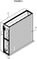
- Mounted perspective view of the modular evaporative cooling system.
- Figure 5:
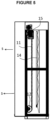
- A side view of the modular evaporative cooling system.
-
- 10. Pre-cooling system
- 11. Mesh mechanism
- 12. Rotating element
- 13. Nozzle
- 14. Transmission element
- 15. Actuation element
- 16. External air louvre
- 17. Drift eliminator
- 18. Container
- 19. Nozzle frame
- S- Cooling direction
- The invention is a modular pre-cooling system (10) which can be applied externally without disturbing the original structure of the system or units when the outdoor temperature of the dry type refrigerant and central cooling systems required for comfort or process cooling of natural gas and geothermal power plants is higher than the ISO design conditions, comprising a mesh mechanism (11), a rotating element (12), a nozzle (13), a transmission element (14), an actuation element (15), a pump and temperature sensor, a humidity sensor, and a control unit consisting of differential pressure sensor with microprocessor.
- As an its inventive feature, the present invention comprises a mesh mechanism (11) which is rotated by an actuation element (15) and positioned in the cooling direction S, which provides a movable surface to which water is sprayed by the nozzle (13). It comprises rotating elements (12) which are rotated by said actuation element (15) and which guide the rotation of the mesh mechanism (11). These rotating elements (12) have a cylindrical structure. Multiple nozzles (13) comprises multiple nozzle frames (19) for securing their places and at least one drift eliminator (17) positioned towards the cooling direction (S). On the other hand, it includes the external air louvres (16) which does not face towards the said cooling direction (S) are positioned on the front surface of the modular system where the external air suction is initiated.
- The mesh mechanism (11) and the outer air louvre (16), comprising of double-ply mesh structure, located at the front or rear side of the pre-cooling system (10), or at the rear of the pre-cooling system so that the two meshes are at a certain distance, are intended to prevent the wind direction and intensity depending on the external environment from influencing the pulverized water coming out of the said nozzles (13) during the operation of the pre-cooling system (10). This prevention is provided by a tarpaulin or sheet metal partition that surrounds the sides of the pre-cooling system (10), allowing air to flow in one direction. Thanks to the double-ply structure of the mesh mechanism (11), the water at the dew point (the point where the air humidity reaches its maximum value) that is not evaporated by air gets caught into the both the first and the second meshes, so that the water is prevented from passing through the pre-cooling system (10). At the same time, in a dusty or dirty atmosphere caused by changing ambient conditions according to the location of power plants or comfort or process cooling systems, the dirt or dust particles circulating in the air are prevented from entering the cooling system (10) by getting them caught to the mesh mechanism (11) with a double-ply structure on the pre-cooling system (10).
- The rotating elements (12), which rotate at a low speed constantly or are fixed, are located one under the other in the + y and -y direction of the "t" axis, which is assumed to pass through the center of the pre-cooling system (10). The said rotating elements (12) are drums with cylindrical geometries and are driven by the actuation element (15). At the edge of said rotating elements (12), with a deckle-edged front, at where the mesh mechanism (11) of the pre-cooling system (10) is attached, there are teeth formed by rubber, gum, etc., which are connected to the actuation element (15) and which make the mesh mechanism (11) rotate together with the rotating elements (12) or the ear chain system to which the meshes are connected. The rotating elements (12) connected to the actuation element (15) in the pre-cooling system (10) are always rotating, turning the mesh mechanism (11) which is connected to it, in a sense, the meshes next to the t-axis are continuously rotated to provide rotation.
- In the said pre-cooling system (10), at the surface assumed to be in contact with the t-axis assumed to pass through the center of the pre-cooling system (10), there are nozzles (13) positioned in the middle of the front and rear of the mesh mechanism (11) to provide spraying to the pre-cooling system (10) and in the opposite direction to the air suction direction.
- The nozzles (13) connected to the transmission element (14) of the cooling system (10) are positioned in front of the rotating elements (12) in the + y and -y direction of the t axis and the mesh mechanism (11) surrounding them. Said nozzles (13) spray water in the opposite direction of the air. In this way, the pulverized water is separated from each other by crashing in the air and the angle is expanded. With this effect, an evaporative action in the center of the mesh mechanism (11) is followed by a second evaporative effect, and via creating a kind of pressure lossless separator by getting caught the water particles that are likely to return into the back mesh, not only water is prevented from leaking from the system, but also a more efficient cooling is provided through a third evaporative effect.
- Said transmission element (14) is a pipe which feeds water coming to the pre-cooling system (10) into the nozzles (13).
- Control unit, which controls the air saturation according to the temperature and humidity values of the air, and the pollution of the water coming from the pump, consists of temperature sensor, humidity sensor and differential pressure sensors. The amount of water to be sprayed from said nozzles (13) is carried out by the temperature sensor, humidity sensor and differential pressure sensors to be positioned at the back and front side of the pre-cooling system (10).
- The temperature sensor and humidity sensors monitor the air values instantly and transmit the data to the microprocessor to which it is connected. The microprocessor provides the psychrometric calculation of the water required for the saturation of air according to the data received from the temperature sensor and humidity sensors. As a result of the calculation, the microprocessor automatically adjusts the number of water and the number of the nozzles (13) to be operated or the flow rate of the speed controlled pumps. The differential pressure sensors control the contamination of the network device and the drift eliminator (17) through the pump feeding the water to be used by the nozzle (13) for spraying.
Claims (7)
- A modular pre-cooling system (10) which can be applied externally to ambient suction air of dry type refrigerant and central cooling systems required for comfort or process cooling of natural gas and geothermal power plants without disturbing the original structure of the system or units, comprising a transmission element (14) to provide water flow, and nozzles (13) to spray the water coming from the said transmission element (14), wherein; it comprises,• a mesh mechanism (11) comprising double-ply mesh structure, which is rotatable by an actuation element (15), located as facing to a cooling direction (S), and which provides a movable surface to which water is sprayed by said nozzles (13),• rotating elements (12) which are rotated by said actuation element (15) and which guide a rotation of the mesh mechanism (11),characterized in that:- the mesh mechanism (11) with a double-ply mesh structure is configured to catch the amount of water that is not evaporated by air, and thus prevents passage/leakage of water from said pre-cooling system (10)- the nozzles (13) with the transmission element (14) are positioned in front of the rotating elements (12), and the mesh mechanism (11) with the double-ply mesh structure is surrounding the nozzles (13), said nozzles (13) spraying water in the opposite direction to the air suction direction.
- The modular pre-cooling system (10) according to Claim 1 wherein; said rotating
elements (12) have a cylindrical structure. - The modular pre-cooling system (10) according to Claim 1, wherein; it comprises movable double-ply mesh mechanism (11) surrounding the nozzles (13) along the circumference of the t axis 360°, surrounding the rotating elements (12).
- The modular pre-cooling system (10) according to Claim 1, wherein; for securing their places, the said multiple nozzles (13) comprises multiple nozzle frames (19) embodying collector and manifold kit.
- The modular pre-cooling system (10) according to Claim 1, wherein; it comprises at least one drift eliminator (17) positioned towards the cooling direction (S).
- The modular pre-cooling system (10) according to Claim 1, wherein; it comprises external air louvres (16) having mesh at its rear and acting as a wind shield, which does not face towards the said cooling direction (S) and which is positioned on the front surface of the modular system where the ambient air is first entered.
- The modular pre-cooling system (10) according to Claim 1, wherein; in order to eliminate unnecessary water consumption and use of extra chemicals for calcification of pads it comprises: a control unit comprising temperature sensor and humidity sensor that connected to a microprocessor which provides psychrometric calculation of the water required for the saturation of air according to data received from the temperature sensor and humidity sensors and differential pressure sensors that control the contamination of the network device and the drift eliminator (17) through the pump feeding the water to be used by the nozzle (13) for spraying.
Applications Claiming Priority (2)
| Application Number | Priority Date | Filing Date | Title |
|---|---|---|---|
| TR201719470 | 2017-12-04 | ||
| PCT/TR2018/050706 WO2019194767A2 (en) | 2017-12-04 | 2018-11-19 | A modular pre-cooling system |
Publications (4)
| Publication Number | Publication Date |
|---|---|
| EP3721144A2 EP3721144A2 (en) | 2020-10-14 |
| EP3721144A4 EP3721144A4 (en) | 2021-07-28 |
| EP3721144C0 EP3721144C0 (en) | 2023-08-30 |
| EP3721144B1 true EP3721144B1 (en) | 2023-08-30 |
Family
ID=68100831
Family Applications (1)
| Application Number | Title | Priority Date | Filing Date |
|---|---|---|---|
| EP18913594.0A Active EP3721144B1 (en) | 2017-12-04 | 2018-11-19 | A modular pre-cooling system |
Country Status (2)
| Country | Link |
|---|---|
| EP (1) | EP3721144B1 (en) |
| WO (1) | WO2019194767A2 (en) |
Families Citing this family (2)
| Publication number | Priority date | Publication date | Assignee | Title |
|---|---|---|---|---|
| PL4050296T3 (en) | 2021-02-26 | 2023-06-05 | Ovh | Heat exchanger system having a mesh panel |
| GB2610843A (en) * | 2021-09-17 | 2023-03-22 | Ure Sami | Drift mesh for adiabatic / evaporative air inlet cooling kit |
Family Cites Families (12)
| Publication number | Priority date | Publication date | Assignee | Title |
|---|---|---|---|---|
| FR869527A (en) * | 1939-10-30 | 1942-02-04 | Krupp Ag | Evaporative refrigeration unit with vertically mounted trickle elements in plate form |
| US3705479A (en) * | 1969-05-15 | 1972-12-12 | Wilson W Mcpherson | Apparatus for cooling air |
| US3740959A (en) * | 1971-09-16 | 1973-06-26 | F Foss | Humidifier dehumidifier device |
| US5337582A (en) * | 1993-07-29 | 1994-08-16 | Santos Villamor B | Split-type air-conditioning apparatus |
| US5529536A (en) * | 1994-06-07 | 1996-06-25 | Sizemore; Timothy J. | Evaporative cooling/humidifing of a motor vehicle's interior air, utilizing the vehicle's as designed powered ventalation system |
| GB0114589D0 (en) * | 2001-06-15 | 2001-08-08 | Ure Zafer M | Adiabatic air cooling unit |
| US20030221440A1 (en) * | 2002-06-03 | 2003-12-04 | Limehouse George M. | Kit for prolonging life of an air conditioning system |
| WO2011016847A2 (en) * | 2009-07-29 | 2011-02-10 | Beutler Corporation | Evaporative pre-cooler for air cooled heat exchangers |
| TR201007003A2 (en) * | 2010-08-23 | 2011-09-21 | Aks�Yek C�Neyt | Cooling system and method for air cooled chillers. |
| KR101500693B1 (en) * | 2014-03-31 | 2015-03-12 | 주식회사 에스제이환경산업 | Air guide for outdoor unit of air conditioner |
| US10422540B2 (en) * | 2015-10-05 | 2019-09-24 | Matthew Morris | Evaporative cooling device and control system |
| CN107366985A (en) * | 2017-08-17 | 2017-11-21 | 广东美的暖通设备有限公司 | Air-conditioner outdoor unit and there is its air conditioner |
-
2018
- 2018-11-19 EP EP18913594.0A patent/EP3721144B1/en active Active
- 2018-11-19 WO PCT/TR2018/050706 patent/WO2019194767A2/en unknown
Also Published As
| Publication number | Publication date |
|---|---|
| EP3721144A4 (en) | 2021-07-28 |
| EP3721144A2 (en) | 2020-10-14 |
| WO2019194767A3 (en) | 2019-12-26 |
| WO2019194767A2 (en) | 2019-10-10 |
| EP3721144C0 (en) | 2023-08-30 |
Similar Documents
| Publication | Publication Date | Title |
|---|---|---|
| CN101509684B (en) | Communication equipment room energy-conserving system | |
| EP3306247B1 (en) | Air-water heat exchanger structure and method for controlling and enhancing the operation thereof | |
| EP3721144B1 (en) | A modular pre-cooling system | |
| CN106347396B (en) | The energy conserving system that air conditioner condensate water recycles | |
| CN102679478A (en) | All-fresh-air type household evaporative-cooling air conditioner window unit | |
| EP2609374B1 (en) | Cooling system and method for air cooled chillers | |
| CN205299803U (en) | Constant temperature and humidity constant voltage purifies aseptic air conditioner all -in -one | |
| CN104949201A (en) | Cabinet air conditioner | |
| CN103499128A (en) | Cylindrical rotatable packing type direct evaporation cooling air conditioner capable of combining spraying with dripping | |
| CN103968658A (en) | Drying device by adopting water circulation heating of air source heat pump and water circulation condensation and dehumidification | |
| CN204717856U (en) | Cabinet air-conditioner | |
| CN202024427U (en) | Cooling dedusting direct evaporative air cooler | |
| CN201858713U (en) | Dehumidifier for corrosion prevention of cabin | |
| KR20010098148A (en) | Absorption humidifying simultaneous heating using waste heat of adsorptive rotary air conditioner | |
| CN203215875U (en) | Device capable of improving air-cooled air conditioner outdoor unit refrigerating efficiency | |
| CN203177615U (en) | Air source heat pump water circulation heating and water circulation condensation dehumidification drying device | |
| KR100657431B1 (en) | Clean air supply apparatus for coating booth using gas engine heat pump | |
| CN104697076A (en) | Pre-wetting type outdoor air conditioner | |
| JP2015218931A (en) | Auxiliary cooling device of heat exchanger | |
| CN202546944U (en) | Brand new air type evaporative cooling household window machine | |
| CN115095920A (en) | Window type air conditioner | |
| CN211011664U (en) | Modular double-cold-source data center cooling system combined with fresh air | |
| CN211146976U (en) | Spray type condenser, evaporative cooling refrigerator and evaporative cooling air conditioner | |
| CN103615775A (en) | Multi-work-condition recuperative type air processing device and method | |
| CN204629764U (en) | Cabinet air-conditioner |
Legal Events
| Date | Code | Title | Description |
|---|---|---|---|
| STAA | Information on the status of an ep patent application or granted ep patent |
Free format text: STATUS: THE INTERNATIONAL PUBLICATION HAS BEEN MADE |
|
| PUAI | Public reference made under article 153(3) epc to a published international application that has entered the european phase |
Free format text: ORIGINAL CODE: 0009012 |
|
| STAA | Information on the status of an ep patent application or granted ep patent |
Free format text: STATUS: REQUEST FOR EXAMINATION WAS MADE |
|
| 17P | Request for examination filed |
Effective date: 20200703 |
|
| AK | Designated contracting states |
Kind code of ref document: A2 Designated state(s): AL AT BE BG CH CY CZ DE DK EE ES FI FR GB GR HR HU IE IS IT LI LT LU LV MC MK MT NL NO PL PT RO RS SE SI SK SM TR |
|
| AX | Request for extension of the european patent |
Extension state: BA ME |
|
| DAV | Request for validation of the european patent (deleted) | ||
| DAX | Request for extension of the european patent (deleted) | ||
| A4 | Supplementary search report drawn up and despatched |
Effective date: 20210629 |
|
| RIC1 | Information provided on ipc code assigned before grant |
Ipc: F24F 5/00 20060101AFI20210623BHEP Ipc: F24F 6/06 20060101ALI20210623BHEP Ipc: F24F 6/12 20060101ALI20210623BHEP |
|
| STAA | Information on the status of an ep patent application or granted ep patent |
Free format text: STATUS: EXAMINATION IS IN PROGRESS |
|
| 17Q | First examination report despatched |
Effective date: 20221206 |
|
| GRAP | Despatch of communication of intention to grant a patent |
Free format text: ORIGINAL CODE: EPIDOSNIGR1 |
|
| STAA | Information on the status of an ep patent application or granted ep patent |
Free format text: STATUS: GRANT OF PATENT IS INTENDED |
|
| GRAS | Grant fee paid |
Free format text: ORIGINAL CODE: EPIDOSNIGR3 |
|
| GRAA | (expected) grant |
Free format text: ORIGINAL CODE: 0009210 |
|
| STAA | Information on the status of an ep patent application or granted ep patent |
Free format text: STATUS: THE PATENT HAS BEEN GRANTED |
|
| INTG | Intention to grant announced |
Effective date: 20230711 |
|
| AK | Designated contracting states |
Kind code of ref document: B1 Designated state(s): AL AT BE BG CH CY CZ DE DK EE ES FI FR GB GR HR HU IE IS IT LI LT LU LV MC MK MT NL NO PL PT RO RS SE SI SK SM TR |
|
| REG | Reference to a national code |
Ref country code: GB Ref legal event code: FG4D |
|
| REG | Reference to a national code |
Ref country code: CH Ref legal event code: EP |
|
| REG | Reference to a national code |
Ref country code: DE Ref legal event code: R096 Ref document number: 602018056760 Country of ref document: DE |
|
| REG | Reference to a national code |
Ref country code: IE Ref legal event code: FG4D |
|
| U01 | Request for unitary effect filed |
Effective date: 20230919 |
|
| U07 | Unitary effect registered |
Designated state(s): AT BE BG DE DK EE FI FR IT LT LU LV MT NL PT SE SI Effective date: 20230926 |
|
| PG25 | Lapsed in a contracting state [announced via postgrant information from national office to epo] |
Ref country code: GR Free format text: LAPSE BECAUSE OF FAILURE TO SUBMIT A TRANSLATION OF THE DESCRIPTION OR TO PAY THE FEE WITHIN THE PRESCRIBED TIME-LIMIT Effective date: 20231201 |
|
| PG25 | Lapsed in a contracting state [announced via postgrant information from national office to epo] |
Ref country code: IS Free format text: LAPSE BECAUSE OF FAILURE TO SUBMIT A TRANSLATION OF THE DESCRIPTION OR TO PAY THE FEE WITHIN THE PRESCRIBED TIME-LIMIT Effective date: 20231230 |
|
| PG25 | Lapsed in a contracting state [announced via postgrant information from national office to epo] |
Ref country code: RS Free format text: LAPSE BECAUSE OF FAILURE TO SUBMIT A TRANSLATION OF THE DESCRIPTION OR TO PAY THE FEE WITHIN THE PRESCRIBED TIME-LIMIT Effective date: 20230830 Ref country code: NO Free format text: LAPSE BECAUSE OF FAILURE TO SUBMIT A TRANSLATION OF THE DESCRIPTION OR TO PAY THE FEE WITHIN THE PRESCRIBED TIME-LIMIT Effective date: 20231130 Ref country code: IS Free format text: LAPSE BECAUSE OF FAILURE TO SUBMIT A TRANSLATION OF THE DESCRIPTION OR TO PAY THE FEE WITHIN THE PRESCRIBED TIME-LIMIT Effective date: 20231230 Ref country code: HR Free format text: LAPSE BECAUSE OF FAILURE TO SUBMIT A TRANSLATION OF THE DESCRIPTION OR TO PAY THE FEE WITHIN THE PRESCRIBED TIME-LIMIT Effective date: 20230830 Ref country code: GR Free format text: LAPSE BECAUSE OF FAILURE TO SUBMIT A TRANSLATION OF THE DESCRIPTION OR TO PAY THE FEE WITHIN THE PRESCRIBED TIME-LIMIT Effective date: 20231201 |
|
| PGFP | Annual fee paid to national office [announced via postgrant information from national office to epo] |
Ref country code: TR Payment date: 20231202 Year of fee payment: 6 |
|
| PG25 | Lapsed in a contracting state [announced via postgrant information from national office to epo] |
Ref country code: PL Free format text: LAPSE BECAUSE OF FAILURE TO SUBMIT A TRANSLATION OF THE DESCRIPTION OR TO PAY THE FEE WITHIN THE PRESCRIBED TIME-LIMIT Effective date: 20230830 |
|
| PG25 | Lapsed in a contracting state [announced via postgrant information from national office to epo] |
Ref country code: ES Free format text: LAPSE BECAUSE OF FAILURE TO SUBMIT A TRANSLATION OF THE DESCRIPTION OR TO PAY THE FEE WITHIN THE PRESCRIBED TIME-LIMIT Effective date: 20230830 |
|
| PG25 | Lapsed in a contracting state [announced via postgrant information from national office to epo] |
Ref country code: SM Free format text: LAPSE BECAUSE OF FAILURE TO SUBMIT A TRANSLATION OF THE DESCRIPTION OR TO PAY THE FEE WITHIN THE PRESCRIBED TIME-LIMIT Effective date: 20230830 Ref country code: RO Free format text: LAPSE BECAUSE OF FAILURE TO SUBMIT A TRANSLATION OF THE DESCRIPTION OR TO PAY THE FEE WITHIN THE PRESCRIBED TIME-LIMIT Effective date: 20230830 Ref country code: ES Free format text: LAPSE BECAUSE OF FAILURE TO SUBMIT A TRANSLATION OF THE DESCRIPTION OR TO PAY THE FEE WITHIN THE PRESCRIBED TIME-LIMIT Effective date: 20230830 Ref country code: CZ Free format text: LAPSE BECAUSE OF FAILURE TO SUBMIT A TRANSLATION OF THE DESCRIPTION OR TO PAY THE FEE WITHIN THE PRESCRIBED TIME-LIMIT Effective date: 20230830 Ref country code: SK Free format text: LAPSE BECAUSE OF FAILURE TO SUBMIT A TRANSLATION OF THE DESCRIPTION OR TO PAY THE FEE WITHIN THE PRESCRIBED TIME-LIMIT Effective date: 20230830 |
|
| REG | Reference to a national code |
Ref country code: DE Ref legal event code: R097 Ref document number: 602018056760 Country of ref document: DE |
|
| PG25 | Lapsed in a contracting state [announced via postgrant information from national office to epo] |
Ref country code: MC Free format text: LAPSE BECAUSE OF FAILURE TO SUBMIT A TRANSLATION OF THE DESCRIPTION OR TO PAY THE FEE WITHIN THE PRESCRIBED TIME-LIMIT Effective date: 20230830 |
|
| U21 | Renewal fee paid with penalty [unitary effect] |
Year of fee payment: 6 Effective date: 20240528 |
|
| PLBE | No opposition filed within time limit |
Free format text: ORIGINAL CODE: 0009261 |
|
| STAA | Information on the status of an ep patent application or granted ep patent |
Free format text: STATUS: NO OPPOSITION FILED WITHIN TIME LIMIT |
|
| PGFP | Annual fee paid to national office [announced via postgrant information from national office to epo] |
Ref country code: CH Payment date: 20240528 Year of fee payment: 6 |
|
| GBPC | Gb: european patent ceased through non-payment of renewal fee |
Effective date: 20231130 |
|
| PG25 | Lapsed in a contracting state [announced via postgrant information from national office to epo] |
Ref country code: MC Free format text: LAPSE BECAUSE OF FAILURE TO SUBMIT A TRANSLATION OF THE DESCRIPTION OR TO PAY THE FEE WITHIN THE PRESCRIBED TIME-LIMIT Effective date: 20230830 |
|
| 26N | No opposition filed |
Effective date: 20240603 |