EP3721123B1 - Compact control valve - Google Patents
Compact control valve Download PDFInfo
- Publication number
- EP3721123B1 EP3721123B1 EP18830918.1A EP18830918A EP3721123B1 EP 3721123 B1 EP3721123 B1 EP 3721123B1 EP 18830918 A EP18830918 A EP 18830918A EP 3721123 B1 EP3721123 B1 EP 3721123B1
- Authority
- EP
- European Patent Office
- Prior art keywords
- bell
- rotor
- needle
- probe
- stator
- Prior art date
- Legal status (The legal status is an assumption and is not a legal conclusion. Google has not performed a legal analysis and makes no representation as to the accuracy of the status listed.)
- Active
Links
- 230000005291 magnetic effect Effects 0.000 claims description 78
- 239000000523 sample Substances 0.000 claims description 42
- 239000012530 fluid Substances 0.000 claims description 22
- 230000033001 locomotion Effects 0.000 claims description 20
- 230000001105 regulatory effect Effects 0.000 claims description 13
- 230000004907 flux Effects 0.000 claims description 10
- 238000007789 sealing Methods 0.000 claims description 10
- 230000005415 magnetization Effects 0.000 claims description 6
- 239000013598 vector Substances 0.000 claims description 5
- 230000005294 ferromagnetic effect Effects 0.000 claims description 4
- 238000000034 method Methods 0.000 claims description 2
- 238000006073 displacement reaction Methods 0.000 description 13
- 239000013529 heat transfer fluid Substances 0.000 description 10
- 230000001939 inductive effect Effects 0.000 description 6
- 230000035945 sensitivity Effects 0.000 description 5
- 238000004378 air conditioning Methods 0.000 description 4
- 230000004323 axial length Effects 0.000 description 4
- 230000008878 coupling Effects 0.000 description 4
- 238000010168 coupling process Methods 0.000 description 4
- 238000005859 coupling reaction Methods 0.000 description 4
- 238000005259 measurement Methods 0.000 description 4
- 230000008901 benefit Effects 0.000 description 3
- 230000009466 transformation Effects 0.000 description 3
- 238000013519 translation Methods 0.000 description 3
- 238000013459 approach Methods 0.000 description 2
- 230000033228 biological regulation Effects 0.000 description 2
- 238000010276 construction Methods 0.000 description 2
- 238000001816 cooling Methods 0.000 description 2
- 230000002452 interceptive effect Effects 0.000 description 2
- 239000000463 material Substances 0.000 description 2
- 230000005226 mechanical processes and functions Effects 0.000 description 2
- 230000004048 modification Effects 0.000 description 2
- 238000012986 modification Methods 0.000 description 2
- 230000005355 Hall effect Effects 0.000 description 1
- 241000897276 Termes Species 0.000 description 1
- QJVKUMXDEUEQLH-UHFFFAOYSA-N [B].[Fe].[Nd] Chemical compound [B].[Fe].[Nd] QJVKUMXDEUEQLH-UHFFFAOYSA-N 0.000 description 1
- KPLQYGBQNPPQGA-UHFFFAOYSA-N cobalt samarium Chemical compound [Co].[Sm] KPLQYGBQNPPQGA-UHFFFAOYSA-N 0.000 description 1
- 239000004020 conductor Substances 0.000 description 1
- 230000001276 controlling effect Effects 0.000 description 1
- 239000002826 coolant Substances 0.000 description 1
- 230000001627 detrimental effect Effects 0.000 description 1
- 230000005611 electricity Effects 0.000 description 1
- 230000007613 environmental effect Effects 0.000 description 1
- 230000006698 induction Effects 0.000 description 1
- 238000009434 installation Methods 0.000 description 1
- 230000010354 integration Effects 0.000 description 1
- 230000005923 long-lasting effect Effects 0.000 description 1
- 229910001172 neodymium magnet Inorganic materials 0.000 description 1
- 230000000737 periodic effect Effects 0.000 description 1
- 238000012545 processing Methods 0.000 description 1
- 230000000750 progressive effect Effects 0.000 description 1
- 238000005057 refrigeration Methods 0.000 description 1
- 230000004044 response Effects 0.000 description 1
- 229910000938 samarium–cobalt magnet Inorganic materials 0.000 description 1
- 238000000926 separation method Methods 0.000 description 1
- 230000035899 viability Effects 0.000 description 1
- 238000003466 welding Methods 0.000 description 1
- 229910000859 α-Fe Inorganic materials 0.000 description 1
Images


Classifications
-
- F—MECHANICAL ENGINEERING; LIGHTING; HEATING; WEAPONS; BLASTING
- F16—ENGINEERING ELEMENTS AND UNITS; GENERAL MEASURES FOR PRODUCING AND MAINTAINING EFFECTIVE FUNCTIONING OF MACHINES OR INSTALLATIONS; THERMAL INSULATION IN GENERAL
- F16K—VALVES; TAPS; COCKS; ACTUATING-FLOATS; DEVICES FOR VENTING OR AERATING
- F16K31/00—Actuating devices; Operating means; Releasing devices
- F16K31/02—Actuating devices; Operating means; Releasing devices electric; magnetic
- F16K31/04—Actuating devices; Operating means; Releasing devices electric; magnetic using a motor
-
- F—MECHANICAL ENGINEERING; LIGHTING; HEATING; WEAPONS; BLASTING
- F16—ENGINEERING ELEMENTS AND UNITS; GENERAL MEASURES FOR PRODUCING AND MAINTAINING EFFECTIVE FUNCTIONING OF MACHINES OR INSTALLATIONS; THERMAL INSULATION IN GENERAL
- F16K—VALVES; TAPS; COCKS; ACTUATING-FLOATS; DEVICES FOR VENTING OR AERATING
- F16K37/00—Special means in or on valves or other cut-off apparatus for indicating or recording operation thereof, or for enabling an alarm to be given
- F16K37/0025—Electrical or magnetic means
- F16K37/0033—Electrical or magnetic means using a permanent magnet, e.g. in combination with a reed relays
-
- F—MECHANICAL ENGINEERING; LIGHTING; HEATING; WEAPONS; BLASTING
- F16—ENGINEERING ELEMENTS AND UNITS; GENERAL MEASURES FOR PRODUCING AND MAINTAINING EFFECTIVE FUNCTIONING OF MACHINES OR INSTALLATIONS; THERMAL INSULATION IN GENERAL
- F16K—VALVES; TAPS; COCKS; ACTUATING-FLOATS; DEVICES FOR VENTING OR AERATING
- F16K27/00—Construction of housing; Use of materials therefor
- F16K27/02—Construction of housing; Use of materials therefor of lift valves
- F16K27/029—Electromagnetically actuated valves
-
- F—MECHANICAL ENGINEERING; LIGHTING; HEATING; WEAPONS; BLASTING
- F16—ENGINEERING ELEMENTS AND UNITS; GENERAL MEASURES FOR PRODUCING AND MAINTAINING EFFECTIVE FUNCTIONING OF MACHINES OR INSTALLATIONS; THERMAL INSULATION IN GENERAL
- F16K—VALVES; TAPS; COCKS; ACTUATING-FLOATS; DEVICES FOR VENTING OR AERATING
- F16K31/00—Actuating devices; Operating means; Releasing devices
- F16K31/02—Actuating devices; Operating means; Releasing devices electric; magnetic
- F16K31/04—Actuating devices; Operating means; Releasing devices electric; magnetic using a motor
- F16K31/047—Actuating devices; Operating means; Releasing devices electric; magnetic using a motor characterised by mechanical means between the motor and the valve, e.g. lost motion means reducing backlash, clutches, brakes or return means
-
- F—MECHANICAL ENGINEERING; LIGHTING; HEATING; WEAPONS; BLASTING
- F16—ENGINEERING ELEMENTS AND UNITS; GENERAL MEASURES FOR PRODUCING AND MAINTAINING EFFECTIVE FUNCTIONING OF MACHINES OR INSTALLATIONS; THERMAL INSULATION IN GENERAL
- F16K—VALVES; TAPS; COCKS; ACTUATING-FLOATS; DEVICES FOR VENTING OR AERATING
- F16K31/00—Actuating devices; Operating means; Releasing devices
- F16K31/44—Mechanical actuating means
- F16K31/50—Mechanical actuating means with screw-spindle or internally threaded actuating means
- F16K31/504—Mechanical actuating means with screw-spindle or internally threaded actuating means the actuating means being rotable, rising, and having internal threads which co-operate with threads on the outside of the valve body
-
- F—MECHANICAL ENGINEERING; LIGHTING; HEATING; WEAPONS; BLASTING
- F25—REFRIGERATION OR COOLING; COMBINED HEATING AND REFRIGERATION SYSTEMS; HEAT PUMP SYSTEMS; MANUFACTURE OR STORAGE OF ICE; LIQUEFACTION SOLIDIFICATION OF GASES
- F25B—REFRIGERATION MACHINES, PLANTS OR SYSTEMS; COMBINED HEATING AND REFRIGERATION SYSTEMS; HEAT PUMP SYSTEMS
- F25B41/00—Fluid-circulation arrangements
- F25B41/30—Expansion means; Dispositions thereof
- F25B41/31—Expansion valves
- F25B41/34—Expansion valves with the valve member being actuated by electric means, e.g. by piezoelectric actuators
- F25B41/35—Expansion valves with the valve member being actuated by electric means, e.g. by piezoelectric actuators by rotary motors, e.g. by stepping motors
-
- H—ELECTRICITY
- H02—GENERATION; CONVERSION OR DISTRIBUTION OF ELECTRIC POWER
- H02K—DYNAMO-ELECTRIC MACHINES
- H02K7/00—Arrangements for handling mechanical energy structurally associated with dynamo-electric machines, e.g. structural association with mechanical driving motors or auxiliary dynamo-electric machines
- H02K7/06—Means for converting reciprocating motion into rotary motion or vice versa
-
- H—ELECTRICITY
- H02—GENERATION; CONVERSION OR DISTRIBUTION OF ELECTRIC POWER
- H02K—DYNAMO-ELECTRIC MACHINES
- H02K7/00—Arrangements for handling mechanical energy structurally associated with dynamo-electric machines, e.g. structural association with mechanical driving motors or auxiliary dynamo-electric machines
- H02K7/14—Structural association with mechanical loads, e.g. with hand-held machine tools or fans
-
- H—ELECTRICITY
- H02—GENERATION; CONVERSION OR DISTRIBUTION OF ELECTRIC POWER
- H02K—DYNAMO-ELECTRIC MACHINES
- H02K11/00—Structural association of dynamo-electric machines with electric components or with devices for shielding, monitoring or protection
- H02K11/20—Structural association of dynamo-electric machines with electric components or with devices for shielding, monitoring or protection for measuring, monitoring, testing, protecting or switching
- H02K11/21—Devices for sensing speed or position, or actuated thereby
- H02K11/215—Magnetic effect devices, e.g. Hall-effect or magneto-resistive elements
-
- H—ELECTRICITY
- H02—GENERATION; CONVERSION OR DISTRIBUTION OF ELECTRIC POWER
- H02K—DYNAMO-ELECTRIC MACHINES
- H02K21/00—Synchronous motors having permanent magnets; Synchronous generators having permanent magnets
- H02K21/12—Synchronous motors having permanent magnets; Synchronous generators having permanent magnets with stationary armatures and rotating magnets
- H02K21/14—Synchronous motors having permanent magnets; Synchronous generators having permanent magnets with stationary armatures and rotating magnets with magnets rotating within the armatures
- H02K21/16—Synchronous motors having permanent magnets; Synchronous generators having permanent magnets with stationary armatures and rotating magnets with magnets rotating within the armatures having annular armature cores with salient poles
-
- H—ELECTRICITY
- H02—GENERATION; CONVERSION OR DISTRIBUTION OF ELECTRIC POWER
- H02K—DYNAMO-ELECTRIC MACHINES
- H02K2201/00—Specific aspects not provided for in the other groups of this subclass relating to the magnetic circuits
- H02K2201/12—Transversal flux machines
-
- Y—GENERAL TAGGING OF NEW TECHNOLOGICAL DEVELOPMENTS; GENERAL TAGGING OF CROSS-SECTIONAL TECHNOLOGIES SPANNING OVER SEVERAL SECTIONS OF THE IPC; TECHNICAL SUBJECTS COVERED BY FORMER USPC CROSS-REFERENCE ART COLLECTIONS [XRACs] AND DIGESTS
- Y02—TECHNOLOGIES OR APPLICATIONS FOR MITIGATION OR ADAPTATION AGAINST CLIMATE CHANGE
- Y02B—CLIMATE CHANGE MITIGATION TECHNOLOGIES RELATED TO BUILDINGS, e.g. HOUSING, HOUSE APPLIANCES OR RELATED END-USER APPLICATIONS
- Y02B30/00—Energy efficient heating, ventilation or air conditioning [HVAC]
- Y02B30/70—Efficient control or regulation technologies, e.g. for control of refrigerant flow, motor or heating
Definitions
- the invention relates to a compact regulating valve, intended for example for a pressure reducing device for an air conditioning circuit, the actuation of which is carried out by a brushless electric motor.
- the present invention is intended in a privileged, but not limited to, the field of flow control valves for air conditioning or battery cooling circuits.
- the particularity of these systems is the need to maintain the heat transfer fluid in a sealed circuit.
- the solution generally adopted, ensuring this seal while allowing long-lasting actuation, is to separate the fixed part, not immersed in the fluid, of a brushless electric motor or of a solenoid, generally the stator of the motor, from a mobile element moving in the fluid circuit, the separation being carried out by a sealed non-magnetic element. Flow rate adjustment is then possible without compromising the tightness of the refrigeration circuit.
- These regulation systems require great compactness, energy efficiency, great control precision, and adaptability to the various mechanical configurations of the fluid circuit.
- the rotor is of shorter axial length than the axial length of the stator.
- the torque generated by the electrical machine therefore remains constant over the entire stroke.
- the force generated is therefore therefore also constant over the stroke of the actuator.
- This embodiment poses a problem in terms of axial size with a need for guidance on either side of the rotor added to the fact that the axial height of the stator is greater than the rotor.
- the demand US2009 / 0294713 introduces a fixed screw and a guide inside the rotor of the motor, in order to solve the aforementioned problems, but the use of a transverse flux motor induces damage to the assembly.
- the transverse flow machine has two electric phases superimposed axially.
- the axial displacement of the rotor induces a progressive imbalance in the torque generated by each phase, so that the regularity of the total torque and therefore the performance is degraded.
- the stacking of the phases of the transverse motor penalizes axial compactness.
- a transverse flux motor has two coils describing a circular torus whose axis is parallel to the main axis of the movement, associated here with a screw-nut transformation.
- the fixed screw linked to the part associated with the coolant inlets is hollowed out in a shape of revolution and along the main axis of the movement to allow the flow rate adjustment needle to pass, the nut being mechanically linked to the motor rotor.
- the motor rotor moves helically during the operation of the expansion valve. It should be noted that, as in the patent US4650156 , the axial length of the rotor is smaller than the axial length of the stator part.
- the object of these devices is to solve the general problem of regulating a fluid flow rate, for example heat transfer fluid, in a linear manner, by associating a mechatronic system with a fluid circuit.
- the devices described above still have a construction which leads to a significant axial bulk with either a transformation of movement as well as guide elements located, axially, on either side of the electric motor, or a construction of the electric motor with transverse flow inducing two superimposed coils.
- the solutions using axial flow motors generally have lateral output connectors which induce a large footprint and a large size.
- the electrical and mechanical connections of the various elements would be problematic due to the distance between the connectors of the 2 components.
- the present invention aims to overcome the drawbacks of the state of the art by producing an actuator that is more compact and efficient than those of the prior art.
- the invention relates to a device comprising an electric motor of not entirely cylindrical shape making it possible to release areas where the fixing means can be integrated without interfering with the coils of the electric motor.
- the invention relates to a device comprising an electric motor of not entirely cylindrical shape making it possible to release areas where the fastening means can be integrated without interfering with the coils of the electric motor and in outside the volume described by the box carrying the stator part. The sealing of the electric motor vis-à-vis the projections of external fluid is then facilitated.
- the invention also relates to the implementation of a needle position sensor as well as a solution for increasing the precision of the axial sensor according to the variations in temperature of the fluid, by introducing a thermally conductive element between the sealing bell where is located the part generating the magnetic field, and the magnetic measurement probe located outside.
- the latter can, by its internal architecture, be temperature compensated but it is located in the volume described by the box, outside the bell separating the rotor from the stator, and can indeed experience a temperature different from that of the fluid.
- the biggest precision is obtained when the temperature gradient is minimal between the probe and the field generating element, the compensation then being carried out on the more precisely known temperature field variation.
- the invention relates more particularly to a valve for regulating the circulation of a fluid having a valve body and a housing containing an electric motor composed of a stator and a rotor, a needle, a sealing bell as well as a housing.
- fixed screw or a fixed nut said fixed screw or said fixed nut being integral with the valve body
- the stator being integral with the valve body via said housing
- the sealing bell being positioned at the interface between the rotor and the stator so that the screw / nut, the rotor and the needle are inside this bell and immersed in said fluid
- the stator being isolated from said fluid
- the rotor having the function of a nut or d 'a screw and having a helical movement imposed by said fixed screw or said fixed nut and driving the needle axially characterized in that the motor is a brushless polyphase motor with radial main magnetic flux.
- a linear position sensor for the needle composed of a magnetosensitive probe secured to the housing outside said bell and detecting an axial component of the magnetic field, as well as at least one magnetic element secured to said needle or to said rotor. inside said bell and generating said magnetic field and located inside said bell.
- said sensor can have a magnet integral with the probe outside the bell, the direction of the magnetization of the magnet being in the axial direction of movement of the needle and following the same orientation than that of the magnetic element.
- a linear position sensor for the needle is made up of a magnetosensitive probe integral with the housing outside said bell and detecting an axial component of the magnetic field, with at least one integral magnet. of said probe outside the bell and generating said magnetic field as well as of a magnetic element, in the form of a soft ferromagnetic part, integral with the needle and located inside said bell and modifying, at the level of the probe, the characteristics (intensity, direction, etc.) of the magnetic field emitted by said magnet.
- said probe is positioned close to the bell and a thermally conductive element is placed at the interface between said probe and said bell.
- the valve can alternatively have an angular position sensor of the rotor composed of a magnetosensitive probe detecting and processing the two Cartesian components of the magnetic field or the phase of the magnetic vector in a plane orthogonal to the axis of axial displacement of the needle and close to it. of the axis of rotation of the motor, said probe being located outside said bell, as well as at least one magnetic element generating said magnetic field and located inside said bell, integral with said rotor.
- the magnetic element emitting the field is, for example, an axial bipolar magnet.
- the invention also relates to a valve body which has a flat receiving surface and a housing fixed to said valve body on said receiving surface by axial fixing means.
- the stator having a triangular shape and at least one fixing element is placed between the vertices of said triangular shape.
- the fixing elements are alternately located at least partly inside a circle passing through said vertices of the triangular shape or else the stator has an external shape, at least in part, circular and at least one element fixing is placed outside the stator part of the motor and at least partly inside a circle inscribed with the stator.
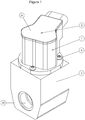
- the figure 1 represents an isometric view of a first embodiment of a valve according to the invention, associating an electrical actuation assembly and a mechanical assembly creating a circulation path for a heat transfer fluid.
- the valve is thus more particularly composed of an electric actuator (1) which translates, along the axis (3) of movement, a needle (not visible here) using an electric motor.
- the actuator (1) is fixed to the valve body (2) which comprises the passage channels (25) of a heat transfer fluid, the flow of which is managed by said needle.
- the electric actuator (1) comprises a cover (24) on the upper part, and is fixed to the valve body (2) by axial fixing means (4), such as screws or bolts.
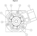
- the figure 2 is a top view of the first embodiment without a cover and making it possible to appreciate the electric actuator with radial magnetic flux typically used in the present invention.
- This actuator (1) has a stator (6) formed from a bundle of sheets forming teeth on which are placed, for some of them, electric coils (8), here 3 coils at 120 ° from each other. .
- the particular shape of the stator, here triangular, makes it possible to accommodate axial fixing elements (4) without increasing the overall footprint of the actuator on the body of the actuator.
- valve (2) The angular freedom of positioning of these elements allows easy orientation of the actuator, particularly of its connector (5), according to the needs of the entire air conditioning system. A simple flat footprint of the valve body (2) thus allows the reception of this actuator which does not have a symmetry of revolution.
- the inscribed circle (7) with the triangular shape of the stator (6) fictitiously intersects, and in axial projection, the fixing elements (4).
- the actuator (1) is encompassed by a housing (9) which can be a housing in which the actuator (1) is placed or else an overmolded plastic material.
- a sealing bell (16) inside which is placed the rotor of the actuator (1) as well as the needle to be moved, these elements being immersed in the heat transfer fluid. Outside this bell are, isolated from the heat transfer fluid, the stator (6) and the coils (8).
- the figure 3 shows a longitudinal section of a valve according to this first embodiment.
- the actuator (1) is screwed onto the valve body (2) using the fasteners (4).
- the valve body (2) has channels (25) for the inlet and outlet of heat transfer fluid.
- the passage of fluid is managed by the positioning of the end of the needle (11) managed by the electric actuator (1), along the axis (3), in order to bring this needle end (11) closer or further away.
- needle seat (17) The rotor (12) is composed of a nut part (14) and which here also forms, in this particular embodiment, the yoke and the support of the permanent magnets (13), the rotor setting in motion the needle ( 11) by a connection here integral but which can be indirect via a spring at the interface (not shown).
- the nut part (14) can be ferromagnetic in order to allow the guiding of the magnetic flux of the magnets (13) and have a mechanical function in order to guarantee the viability of the motion transformation.
- the movement of the rotor (12) and therefore of the needle (11) follows a helical path thus combining a rotation, that of the electrical machine formed by the rotor (12) and the stator (6), and a translation, imposed by the screwing of the nut part (14) on the screw (15) here fixed and integral with the valve body (2).
- the movement is helical but only the translation component is mechanically important for the adjustment of the valve, the needle having a geometry of revolution.
- the axial height of the rotor (12) is less than that of the pack of sheets (10) so that, during the displacement of the rotor in its helical movement, the linear stroke S of which is delimited on the figures 3 and 7 , the rotor is always radially facing the stator.
- the valve is shown in the closed position and the rotor can therefore go up in the stator without changing the active surfaces facing each other between rotor and stator. Therefore, the torque generated by the motor and therefore the force applied to the needle (11) are not affected during movement.
- the configuration presented here is particularly compact axially with a guide entirely provided in the active height of the package of sheets (10), this guide being here provided by the screw (15) in cooperation with the nut (14) and by the body of the needle (11) with the inner surface of the fixed screw.
- a needle position sensor (11) is shown in this configuration of the figure 3 , and because the use of a radial flow actuator allows it more easily.
- This magnetic principle sensor is located on the upper part of the valve, above the rotor (12).
- a magnetized magnetic element (20a) is integral with the nut part (14), therefore with the rotor (12) and therefore with the needle (11).
- This magnet which has axial magnetization along the axis (3), is itself also immersed inside the bell (16). During the helical movement of the rotor (12), this magnetic element (20a) therefore moves away or approaches the bottom of the bell (16).
- a magnetosensitive probe (19) detecting the amplitude of the axial component of the magnetic field on the axis ( 3) emitted by the magnetic element (20a).
- the distance or the approach of this magnetic element (20a) relative to the magnetosensitive probe (19) thus makes it possible to modulate the amplitude of the field detected by the probe (19) and give the image of the position of the needle (11).
- the importance here is given to the axis of axial sensitivity of the probe (19) because a radial magnetic flux motor generates, on the axis (3), a magnetic field with an axial component much lower than that created by a motor transverse flow. Indeed, here the axial component produced is only a leak whereas it is a main path for the motor of the prior art.
- the probe (19) is carried by a printed circuit (18) located above the bell (16), under the cover (24).
- This printed circuit (18) also carries the connection points to the coils (8) of the actuator (1) as well as the electronic components necessary for controlling the polyphase electric motor.
- the printed circuit (18) also supports, around the probe (19), a compensation magnet (21) which can be optionally used in order to adjust the average level of induction around zero gauss and thus improve the temperature behavior of the sensor. .
- the compensating magnet will, in this case, have an axial magnetization direction in the same direction as the direction of the magnetization of the magnetic element (20a).
- the magnetic element (20a) generating the axial magnetic field is produced as a magnet, based on Neodymium Iron Boron, Ferrite or Samarium cobalt.
- the latter material has the advantage of a low variation in its magnetic properties as a function of temperature, thus minimizing the drifts of the sensor signal and minimizing the influence of temperature gradients between the fluid and the magnetic field measurement probe. .
- the magnetosensitive probe (19) and the magnetic element (20a) emitting field which are located respectively outside and inside the bell (16)
- it can be placed at the interface between the bell (16) and the probe (19) a thermally conductive element (22) allowing the probe (19) to be brought to a temperature close to that inside the bell and therefore at a temperature close to that of the magnetic element (20a).
- the figure 4 shows a partial sectional view of this first embodiment which makes it possible to appreciate in more detail the screw (15) and the components described above, in particular a variant of the position sensor.
- This position sensor can be used to, for example, control the motor in closed loop or simply to know the position of the needle and make sure it is in the desired position.
- the probe (19) can exhibit a magnetic sensitivity to the amplitude of the 2 magnetic field components orthogonal to the axis of displacement or else a sensitivity to the phase of the magnetic field vector orthogonal to the axis of displacement. , in order to determine the angular position of the rotor alone.
- the probe (19) can also have a magnetic sensitivity to the amplitude of the 3 components of the magnetic field or a sensitivity to the phases of the magnetic vectors of the magnetic element (20a) respectively in the plane orthogonal to the axis of displacement and following the axis of displacement, in order to determine both the angular position of the rotor but also the axial position.
- the use, for example, of an MLX90363 type probe makes it possible to measure these three components of the magnetic field.
- the imagined solution proposes to measure the axial distance information from the probe (19) to the rotor (12), with an output of the type proportional to this distance and preferably with the axial component of the field on the axis, and of absolute rotary position.
- the solution allowing the measurement of the amplitude of the 2 components of magnetic field gives indirectly also access to the axial position by the calculation of the modulus of the 2 components coplanar with the axis of displacement.
- This modulus in fact varies as a function of the distance between the magnetic element (20a) and the probe (19).
- the magnet generating the magnetic field may, for example, be the magnetic element (20a) having an axial bipolar magnetization.
- the measuring point of the probe (19) will then be judiciously placed in relation to the magnetic element (20a) in order to exploit the 2 or the 3 components or the phases of the vectors of the magnetic field.
- the knowledge of the absolute position of the rotor (12) on a revolution makes it possible to consider its piloting in a closed loop, while the knowledge of the axial position of the rotor (12) makes it possible to manage the opening / closing of the needle linked to the rotor. . Knowing the position of the rotor alone already allows more robust control of the FOC or sinusoidal type than in pure stepper mode.
- the figure 5 represents a second variant of use where the motor uses a number of electric coils greater than 3 (here 6 are shown), thus modifying the external imprint of the stator.
- This configuration is advantageous in cases where the force requirements linked to the regulation of the fluid, more precisely due to the pressure differences between the various elements of the fluid circuit, are significant.
- the increase in the number of coils in fact increases the force factor produced by the actuator for a given electric power at the input of the actuator.
- This second variant is also distinguished from the first in that the housing (9) has a generally tubular shape with two axial clearances (26) on the periphery in order to allow fixing using the fixing elements (4).
- the figure 6 shows the detail of the magnetic circuit of the actuator (1), the fixing elements (4) being located inside the circle (23) inscribed on the outside of the stator and between the six coils (8) of this part stator.
- the number of fasteners (4) is not limiting, here two are shown but more than two can be considered.
- the total footprint of the actuator with its fixing elements (4) is thus minimized on the valve body and the rectangular shape thereof.
- the orientation of the connector (5) can be variable thanks to the positioning principle and to the fixing elements chosen.
- the probe (19) is shown isolated above this stator in a preferred position, on the displacement axis (not shown here).
- the figure 7 shows an alternative embodiment of the position sensor.
- the magnetic element (20b) is a soft ferromagnetic element which does not emit a magnetic field but modifies the intensity of the magnetic field emitted by the magnet of the sensor (21) surrounding the probe (19). ), and detected at the level of the probe (19) during the axial movement of this magnetic element (20b).
- the magnetic element (20b) can be located either on one side or the other of the printed circuit (18) still outside the bell (16).
- the sensors described in the previous examples are integrated on the rotor but the invention also applies to the case where the magnetic element (20a) or (20b) is integrated on the upper end of the needle (11). .
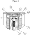
- the figure 8 also presents an alternative embodiment of coupling the rotor with the valve body (2).
- the rotor is integral with the needle (11) which forms a screw (30) which cooperates with a fixed nut (29) linked to the valve body (2).
- the rotor forms a nut and cooperates with a fixed screw portion linked to the valve body (2).
- the invention is in fact not limited in terms of screw / nut functions which can be performed either by the rotor or at the level of the valve body (2).
- the sensor solutions are not limited to the choice of using a screw or nut at the level of the rotor or of the valve body (2) and it can be considered to take a sensor solution and adapt it to one or other of the mechanical solutions envisaged.
Landscapes
- Engineering & Computer Science (AREA)
- General Engineering & Computer Science (AREA)
- Mechanical Engineering (AREA)
- Power Engineering (AREA)
- Physics & Mathematics (AREA)
- Thermal Sciences (AREA)
- Electromagnetism (AREA)
- Electrically Driven Valve-Operating Means (AREA)
- Connection Of Motors, Electrical Generators, Mechanical Devices, And The Like (AREA)
Description
L'invention se rapporte à une vanne de réglage compacte, destinée par exemple à un dispositif de détendeur pour circuit de climatisation et dont l'actionnement est réalisé par un moteur électrique sans balai.The invention relates to a compact regulating valve, intended for example for a pressure reducing device for an air conditioning circuit, the actuation of which is carried out by a brushless electric motor.
La présente invention se destine de manière privilégiée, mais non limitative, au domaine des vannes de réglage de débit pour circuit de climatisation ou de refroidissement de batteries. La particularité de ces systèmes est le besoin de maintenir le fluide caloporteur dans un circuit étanche. La solution généralement adoptée, assurant cette étanchéité tout en permettant un actionnement pérenne, est de séparer la partie fixe, non immergée dans le fluide, d'un moteur électrique sans balai ou d'un solénoïde, généralement le stator du moteur, d'un élément mobile se déplaçant dans le circuit de fluide, la séparation étant réalisée par un élément amagnétique étanche. Le réglage des débits est alors possible sans porter atteinte à l'étanchéité du circuit de réfrigération. Il est demandé à ces systèmes de régulation une grande compacité, une efficience énergétique, une grande précision de commande, et une adaptabilité aux différentes configurations mécaniques du circuit de fluide.The present invention is intended in a privileged, but not limited to, the field of flow control valves for air conditioning or battery cooling circuits. The particularity of these systems is the need to maintain the heat transfer fluid in a sealed circuit. The solution generally adopted, ensuring this seal while allowing long-lasting actuation, is to separate the fixed part, not immersed in the fluid, of a brushless electric motor or of a solenoid, generally the stator of the motor, from a mobile element moving in the fluid circuit, the separation being carried out by a sealed non-magnetic element. Flow rate adjustment is then possible without compromising the tightness of the refrigeration circuit. These regulation systems require great compactness, energy efficiency, great control precision, and adaptability to the various mechanical configurations of the fluid circuit.
Par les nouvelles normes environnementales et par les besoins liés à l'électrification des véhicules pour des raisons de confort évident, d'efficience et parfois de risque, un accroissement des besoins de précision et de sécurité sur la gestion du système complet de climatisation a fait émerger les demandes d'un retour d'information sur la position du pointeau de réglage de ces vannes d'expansion. Aussi par le besoin d'efficience énergétique, il existe donc un besoin de détection de position de la partie active de la vanne lors du réglage.Due to the new environmental standards and the needs related to the electrification of vehicles for reasons of obvious comfort, efficiency and sometimes risk, an increase in the need for precision and safety in the management of the complete air conditioning system has emerge requests for feedback on the position of the adjustment needle of these expansion valves. Also by the need for energy efficiency, there is therefore a need for detecting the position of the active part of the valve during adjustment.
Les forces demandées lors du réglage sont relativement importantes rapportées au volume du système, avec un maximum lors de la fermeture du circuit de fluide caloporteur, lorsque le pointeau s'appuie sur le siège de la vanne. Sur le reste du déplacement possible du pointeau, les forces décroissent, la section de passage du fluide étant de plus en plus grande. Il existe donc un intérêt à adapter la force en fonction de la position de la partie active de la vanne dans le but d'une consommation électrique optimisée.The forces required during adjustment are relatively large compared to the volume of the system, with a maximum when the heat transfer fluid circuit is closed, when the needle rests on the valve seat. On the remainder of the possible displacement of the needle, the forces decrease, the section of passage of the fluid being increasingly large. There is therefore an interest in adapting the force in function of the position of the active part of the valve in order to optimize electricity consumption.
Enfin, ces systèmes sont présents dans les domaines de l'industrie ou de l'habitation, mais également dans le domaine des véhicules automobiles où une nécessité d'intégration compacte est demandée. Il existe donc un besoin de fixation pratique et intégrée de l'actionneur sur le corps de vanne.Finally, these systems are present in the fields of industry or housing, but also in the field of motor vehicles where a need for compact integration is required. There is therefore a need for practical and integrated fixing of the actuator on the valve body.
Dans les documents les plus anciens, il est connu du
Dans ce même document, le rotor est de longueur axiale plus faible que la longueur axiale du stator. Lors du déplacement, la partie rotorique portant l'aimant reste en face de la matière magnétiquement conductrice du stator, le couple généré par la machine électrique reste donc constant sur l'ensemble de la course. La force générée est donc par conséquent également constante sur la course de l'actionneur. Cette réalisation pose un problème en termes d'encombrement axial avec un besoin de guidage de part et d'autre du rotor ajouté au fait que la hauteur axiale de stator est plus importante que le rotor.In this same document, the rotor is of shorter axial length than the axial length of the stator. During movement, the rotor part carrying the magnet remains opposite the magnetically conductive material of the stator, the torque generated by the electrical machine therefore remains constant over the entire stroke. The force generated is therefore therefore also constant over the stroke of the actuator. This embodiment poses a problem in terms of axial size with a need for guidance on either side of the rotor added to the fact that the axial height of the stator is greater than the rotor.
Dans cet état de l'art ancien on trouve aussi, dans le document
Plus récemment, la demande
En effet, un moteur à flux transverse présente deux bobines décrivant un tore circulaire dont l'axe est parallèle à l'axe principal du mouvement, associé ici à une transformation vis-écrou. La vis fixe liée à la partie associée aux arrivées de fluide caloporteur est évidée suivant une forme de révolution et suivant l'axe principal du mouvement pour laisser passer le pointeau de réglage de débit, l'écrou étant lié mécaniquement au rotor du moteur. Le rotor du moteur se déplace de manière hélicoïdale lors du fonctionnement de la vanne d'expansion. Il est à noter que, comme dans le
Plus récemment encore, dans le document
Ces dispositifs ont pour objet de résoudre le problème général de régler de manière linéaire un débit de fluide, par exemple caloporteur, en associant un système mécatronique à un circuit de fluide.The object of these devices is to solve the general problem of regulating a fluid flow rate, for example heat transfer fluid, in a linear manner, by associating a mechatronic system with a fluid circuit.
Cependant, les dispositifs décrits précédemment présentent toujours une construction qui mène à un encombrement axial important avec soit une transformation de mouvement ainsi que des éléments de guidage situés, axialement, de part et d'autre du moteur électrique, soit une construction du moteur électrique à flux transverse induisant deux bobines superposées.However, the devices described above still have a construction which leads to a significant axial bulk with either a transformation of movement as well as guide elements located, axially, on either side of the electric motor, or a construction of the electric motor with transverse flow inducing two superimposed coils.
Dans l'optique de disposer d'un capteur de position analogique, c'est à dire donnant une information proportionnelle à un déplacement, l'utilisation d'un moteur à flux transverse n'est pas idéale car le flux magnétique produit par ces bobines sort largement au-dessus du moteur et perturbe de manière conséquente les performances du capteur lorsque celui-ci est un capteur magnétosensible. De plus, dans aucun de ces brevets n'est introduit de capteur permettant de mesurer le déplacement axial du pointeau ou du rotor. En effet, les solutions électromagnétiques du brevet
Dans le document
Du point de vue de l'encombrement des solutions, les solutions utilisant des moteurs à flux axial présentent généralement des connectiques de sortie latérales qui induisent une empreinte large et un grand encombrement. Dans l'éventualité de l'utilisation d'un capteur de position proche de l'axe du pointeau, les liaisons électriques et mécaniques des différents éléments seraient problématiques du fait de l'éloignement des connectiques des 2 composants.From the point of view of the size of the solutions, the solutions using axial flow motors generally have lateral output connectors which induce a large footprint and a large size. In the event of the use of a position sensor close to the axis of the needle, the electrical and mechanical connections of the various elements would be problematic due to the distance between the connectors of the 2 components.
La présente invention vise à pallier les inconvénients de l'état de la technique en réalisant un actionneur plus compact et efficient que ceux de l'art antérieur.The present invention aims to overcome the drawbacks of the state of the art by producing an actuator that is more compact and efficient than those of the prior art.
Il est également dans l'objet de l'invention que de permettre optionnellement l'utilisation d'un capteur de position intégré au moteur et qui permet de déterminer la position linéaire du pointeau.It is also the object of the invention to optionally allow the use of a position sensor integrated into the motor and which makes it possible to determine the linear position of the needle.
Il est aussi dans l'objet de l'invention de permettre l'utilisation d'un capteur de position intégré au moteur et qui permet de déterminer la position angulaire du rotor du moteur.It is also in the object of the invention to allow the use of a position sensor integrated in the motor and which makes it possible to determine the angular position of the rotor of the motor.
Il est encore dans l'objet de l'invention de permettre au moteur de se fixer de manière aisée et rigide sur le corps de vanne sans utilisation de soudure et dans un encombrement limité.It is also in the object of the invention to allow the motor to be fixed easily and rigidly on the valve body without the use of welding and in a limited space.
Selon des modes de réalisation particuliers, l'invention a pour objet un dispositif comportant un moteur électrique de forme non entièrement cylindrique permettant de dégager des zones où les moyens de fixations peuvent s'intégrer sans interférer avec les bobines du moteur électriqueAccording to particular embodiments, the invention relates to a device comprising an electric motor of not entirely cylindrical shape making it possible to release areas where the fixing means can be integrated without interfering with the coils of the electric motor.
Selon d'autres modes de réalisation particuliers, l'invention a pour objet un dispositif comportant un moteur électrique de forme non entièrement cylindrique permettant de dégager des zones où les moyens de fixations peuvent s'intégrer sans interférer avec les bobines du moteur électrique et en dehors du volume décrit par le boitier portant la partie statorique. L'étanchéité du moteur électrique vis-à-vis des projections de fluide extérieur est alors facilitée.According to other particular embodiments, the invention relates to a device comprising an electric motor of not entirely cylindrical shape making it possible to release areas where the fastening means can be integrated without interfering with the coils of the electric motor and in outside the volume described by the box carrying the stator part. The sealing of the electric motor vis-à-vis the projections of external fluid is then facilitated.
L'invention concerne également l'implémentation d'un capteur de position du pointeau ainsi que d'une solution pour accroitre la précision du capteur axial suivant les variations de température du fluide, en introduisant un élément thermiquement conducteur entre la cloche d'étanchéité où est situé la partie générant le champ magnétique, et la sonde de mesure magnétique située à l'extérieur. Cette dernière peut, par son architecture interne, être compensée en température mais elle est située dans le volume décrit par le boitier, en dehors de la cloche séparant le rotor du stator, et peut en effet connaître une température différente de celle du fluide. La plus grande précision est obtenue quand le gradient de température est minimal entre sonde et élément générateur de champ, la compensation étant alors réalisée sur la variation de champ en température plus précisément connue.The invention also relates to the implementation of a needle position sensor as well as a solution for increasing the precision of the axial sensor according to the variations in temperature of the fluid, by introducing a thermally conductive element between the sealing bell where is located the part generating the magnetic field, and the magnetic measurement probe located outside. The latter can, by its internal architecture, be temperature compensated but it is located in the volume described by the box, outside the bell separating the rotor from the stator, and can indeed experience a temperature different from that of the fluid. The biggest precision is obtained when the temperature gradient is minimal between the probe and the field generating element, the compensation then being carried out on the more precisely known temperature field variation.
L'invention concerne plus particulièrement une vanne réglage de circulation d'un fluide présentant un corps de vanne et un boitier contenant un moteur électrique composé d'un stator et d'un rotor, un pointeau, une cloche d'étanchéité ainsi qu'une vis fixe ou un écrou fixe, ladite vis fixe ou ledit écrou fixe étant solidaire du corps de vanne, le stator étant solidaire du corps de vanne par l'intermédiaire dudit boitier, la cloche d'étanchéité étant positionnée à l'interface entre le rotor et le stator de manière à ce que la vis/écrou, le rotor et le pointeau soient à l'intérieur de cette cloche et immergés dans ledit fluide, le stator étant isolé dudit fluide, le rotor ayant la fonction d'un écrou ou d'une vis et ayant un mouvement hélicoïdal imposé par ladite vis fixe ou ledit écrou fixe et entrainant le pointeau axialement caractérisée en ce que le moteur est un moteur polyphasé sans balai à flux magnétique principal radial.The invention relates more particularly to a valve for regulating the circulation of a fluid having a valve body and a housing containing an electric motor composed of a stator and a rotor, a needle, a sealing bell as well as a housing. fixed screw or a fixed nut, said fixed screw or said fixed nut being integral with the valve body, the stator being integral with the valve body via said housing, the sealing bell being positioned at the interface between the rotor and the stator so that the screw / nut, the rotor and the needle are inside this bell and immersed in said fluid, the stator being isolated from said fluid, the rotor having the function of a nut or d 'a screw and having a helical movement imposed by said fixed screw or said fixed nut and driving the needle axially characterized in that the motor is a brushless polyphase motor with radial main magnetic flux.
Avantageusement elle présente un capteur de position linéaire du pointeau composé d'une sonde magnétosensible solidaire du boitier à l'extérieur de ladite cloche et détectant une composante axiale de champ magnétique, ainsi que d'au moins un élément magnétique solidaire dudit pointeau ou dudit rotor à l'intérieur de ladite cloche et générant ledit champ magnétique et situé à l'intérieur de ladite cloche. Afin de permettre une insensibilité au défaut de positionnement ledit capteur peut présenter un aimant solidaire de la sonde à l'extérieur de la cloche, la direction de l'aimantation de l'aimant étant dans le sens axial de déplacement du pointeau et suivant la même orientation que celle de l'élément magnétique.Advantageously, it has a linear position sensor for the needle composed of a magnetosensitive probe secured to the housing outside said bell and detecting an axial component of the magnetic field, as well as at least one magnetic element secured to said needle or to said rotor. inside said bell and generating said magnetic field and located inside said bell. In order to allow insensitivity to the positioning fault, said sensor can have a magnet integral with the probe outside the bell, the direction of the magnetization of the magnet being in the axial direction of movement of the needle and following the same orientation than that of the magnetic element.
Dans une autre implémentation d'un capteur de position linéaire du pointeau, celui-ci est composé d'une sonde magnétosensible solidaire du boitier à l'extérieur de ladite cloche et détectant une composante axiale de champ magnétique, d'au moins un aimant solidaire de ladite sonde à l'extérieur de la cloche et générant ledit champ magnétique ainsi que d'un élément magnétique, sous la forme d'une pièce ferromagnétique douce, solidaire du pointeau et situé à l'intérieur de ladite cloche et modifiant, au niveau de la sonde, les caractéristiques (intensité, direction,...) du champ magnétique émis par ledit aimant.In another implementation of a linear position sensor for the needle, the latter is made up of a magnetosensitive probe integral with the housing outside said bell and detecting an axial component of the magnetic field, with at least one integral magnet. of said probe outside the bell and generating said magnetic field as well as of a magnetic element, in the form of a soft ferromagnetic part, integral with the needle and located inside said bell and modifying, at the level of the probe, the characteristics (intensity, direction, etc.) of the magnetic field emitted by said magnet.
Dans ces solutions de capteur, alternativement, ladite sonde est positionnée à proximité de la cloche et un élément thermiquement conducteur est placé à l'interface entre ladite sonde et ladite cloche.In these sensor solutions, alternatively, said probe is positioned close to the bell and a thermally conductive element is placed at the interface between said probe and said bell.
La vanne peut alternativement présenter un capteur de position angulaire du rotor composé d'une sonde magnétosensible détectant et traitant les deux composantes cartésiennes de champ magnétique ou la phase du vecteur magnétique dans un plan orthogonal à l'axe de déplacement axial du pointeau et à proximité de l'axe de rotation du moteur, ladite sonde étant située à l'extérieur de ladite cloche, ainsi que au moins un élément magnétique générant ledit champ magnétique et situé à l'intérieur de ladite cloche, solidaire dudit rotor. The valve can alternatively have an angular position sensor of the rotor composed of a magnetosensitive probe detecting and processing the two Cartesian components of the magnetic field or the phase of the magnetic vector in a plane orthogonal to the axis of axial displacement of the needle and close to it. of the axis of rotation of the motor, said probe being located outside said bell, as well as at least one magnetic element generating said magnetic field and located inside said bell, integral with said rotor.
Dans ce cas, l'élément magnétique émettant le champ est, par exemple, un aimant bipolaire axial.In this case, the magnetic element emitting the field is, for example, an axial bipolar magnet.
Pour permettre la fixation de l'actionneur au corps de vanne, l'invention concerne aussi un corps de vanne qui présente une surface d'accueil plane et un boitier fixé audit corps de vanne sur ladite surface d'accueil par des moyens de fixations axiaux, le stator présentant une forme triangulaire et au moins un élément de fixation est placé entre les sommets de ladite forme triangulaire.To enable the actuator to be attached to the valve body, the invention also relates to a valve body which has a flat receiving surface and a housing fixed to said valve body on said receiving surface by axial fixing means. , the stator having a triangular shape and at least one fixing element is placed between the vertices of said triangular shape.
Dans ce cas, les éléments de fixation sont alternativement localisés au moins en partie à l'intérieur d'un cercle passant par lesdits sommets de la forme triangulaire ou bien le stator une forme extérieure, au moins en partie, circulaire et au moins un élément de fixation est placé à l'extérieur de la partie statorique du moteur et au moins en partie à l'intérieur d'un cercle inscrit au stator.In this case, the fixing elements are alternately located at least partly inside a circle passing through said vertices of the triangular shape or else the stator has an external shape, at least in part, circular and at least one element fixing is placed outside the stator part of the motor and at least partly inside a circle inscribed with the stator.
D'autres caractéristiques et avantages de l'invention ressortiront à la lecture qui suit d'exemples de réalisation détaillés, en référence aux figures annexées qui représentent respectivement :
- la
figure 1 , une vue en perspective d'une vanne selon l'invention dans un premier mode de réalisation de l'invention ; - la
figure 2 , une vue de dessus et sans couvercle du dispositif de lafigure 1 ; - la
figure 3 , une vue en coupe longitudinale du dispositif de lafigure 1 avec une vue de zone agrandie ; - la
figure 4 , une vue en perspective et en coupe partielle du dispositif de lafigure 1 ; - la
figure 5 , une vue d'une vanne selon l'invention dans un second mode de réalisation de l'invention où le moteur électrique comporte un plus grand nombre de bobines comparé au premier mode ; - la
figure 6 , une vue de dessus et en coupe transversale du dispositif de lafigure 5 ; - la
figure 7 , une vue en coupe longitudinale et de détail d'une solution présentant une alternative à un capteur de position utilisé dans la présente invention ; - la
figure 8 , une vue en coupe longitudinale et de détail d'un mode de réalisation alternatif où le rotor forme une vis et où le capteur utilisé est de principe physique inductif.
- the
figure 1 , a perspective view of a valve according to the invention in a first embodiment of the invention; - the
figure 2 , a top view without cover of the device of thefigure 1 ; - the
figure 3 , a longitudinal sectional view of the device of thefigure 1 with an enlarged area view; - the
figure 4 , a perspective and partial sectional view of the device of thefigure 1 ; - the
figure 5 , a view of a valve according to the invention in a second embodiment of the invention where the electric motor has a greater number of coils compared to the first mode; - the
figure 6 , a top view in cross section of the device of thefigure 5 ; - the
figure 7 , a longitudinal sectional view and detail of a solution presenting an alternative to a position sensor used in the present invention; - the
figure 8 , a longitudinal sectional view and detail of an alternative embodiment where the rotor forms a screw and where the sensor used is of inductive physical principle.
La
La
La
Dans cet exemple de réalisation, la hauteur axiale du rotor (12) est inférieure à celle du paquet de tôles (10) afin que, lors du déplacement du rotor dans son mouvement hélicoïdal, dont la course linéaire S est délimitée sur les
La configuration présentée ici est particulièrement compacte axialement avec un guidage entièrement prévu dans la hauteur active du paquet de tôles (10), ce guidage étant ici réalisé par la vis (15) en coopération avec l'écrou (14) et par le corps du pointeau (11) avec la surface intérieure de la vis fixe.The configuration presented here is particularly compact axially with a guide entirely provided in the active height of the package of sheets (10), this guide being here provided by the screw (15) in cooperation with the nut (14) and by the body of the needle (11) with the inner surface of the fixed screw.
Dans cette configuration de la
La sonde (19) est portée par un circuit imprimé (18) située au-dessus de la cloche (16), sous le couvercle (24). Ce circuit imprimé (18) porte également les points de connexion aux bobines (8) de l'actionneur (1) ainsi que des composants électroniques nécessaires au pilotage du moteur électrique polyphasé. Le circuit imprimé (18) supporte aussi, autour de la sonde (19), un aimant de compensation (21) pouvant être optionnellement utilisé afin de régler le niveau moyen d'induction autour du zéro gauss et améliorer ainsi le comportement en température du capteur. L'aimant de compensation présentera, dans ce cas, une direction d'aimantation axiale dans la même direction que la direction de l'aimantation de l'élément magnétique (20a).The probe (19) is carried by a printed circuit (18) located above the bell (16), under the cover (24). This printed circuit (18) also carries the connection points to the coils (8) of the actuator (1) as well as the electronic components necessary for controlling the polyphase electric motor. The printed circuit (18) also supports, around the probe (19), a compensation magnet (21) which can be optionally used in order to adjust the average level of induction around zero gauss and thus improve the temperature behavior of the sensor. . The compensating magnet will, in this case, have an axial magnetization direction in the same direction as the direction of the magnetization of the magnetic element (20a).
L'élément magnétique (20a) générant le champ magnétique axial est réalisé en aimant, à base de Néodyme Fer Bore, de Ferrite ou de Samarium cobalt. Cette dernière matière présente l'avantage d'une variation faible de ses propriétés magnétiques en fonction de la température, minimisant ainsi les dérives du signal du capteur et minimisant l'influence des gradients de température entre le fluide et la sonde de mesure de champ magnétique.The magnetic element (20a) generating the axial magnetic field is produced as a magnet, based on Neodymium Iron Boron, Ferrite or Samarium cobalt. The latter material has the advantage of a low variation in its magnetic properties as a function of temperature, thus minimizing the drifts of the sensor signal and minimizing the influence of temperature gradients between the fluid and the magnetic field measurement probe. .
Afin d'améliorer l'homogénéité de température entre la sonde magnétosensible (19) et l'élément magnétique (20a) émetteur de champ qui sont situés respectivement à l'extérieur et à l'intérieur de la cloche (16), et dans le but de permettre une compensation en température plus efficace, il peut être placé à l'interface entre la cloche (16) et la sonde (19) un élément thermiquement conducteur (22) permettant de porter la sonde (19) à une température proche de celle à l'intérieur de la cloche et donc à une température proche de celle de l'élément magnétique (20a).In order to improve the temperature homogeneity between the magnetosensitive probe (19) and the magnetic element (20a) emitting field which are located respectively outside and inside the bell (16), and in the In order to allow a more efficient temperature compensation, it can be placed at the interface between the bell (16) and the probe (19) a thermally conductive element (22) allowing the probe (19) to be brought to a temperature close to that inside the bell and therefore at a temperature close to that of the magnetic element (20a).
La
Afin de s'affranchir plus complétement du champ magnétique produit par le stator, l'utilisation d'une sonde « double die », c'est-à-dire à deux éléments magnétosensibles voisins, peut être envisagée dans le cadre d'une mesure différentielle. Un blindage localisé à proximité des bobines afin de court-circuiter le champ parasite émis par celle-ci et/ou proche de la sonde constitue également une solution encore plus robuste.In order to be more completely free from the magnetic field produced by the stator, the use of a "double die" probe, that is to say with two neighboring magnetosensitive elements, can be considered as part of a measurement. differential. A shield located near the coils in order to short-circuit the stray field emitted by the latter and / or close to the probe also constitutes an even more robust solution.
La
Cette deuxième variante se distingue aussi de la première en ce que le boitier (9) présente une forme globalement tubulaire avec deux dégagements axiaux (26) sur la périphérie afin de permettre la fixation à l'aide des éléments de fixation (4).This second variant is also distinguished from the first in that the housing (9) has a generally tubular shape with two axial clearances (26) on the periphery in order to allow fixing using the fixing elements (4).
La
La sonde (19) est montrée isolée au-dessus de ce stator dans une position préférentielle, sur l'axe de déplacement (non montré ici).The probe (19) is shown isolated above this stator in a preferred position, on the displacement axis (not shown here).
La
De manière générale, les capteurs décrits dans les exemples précédents sont intégrés sur le rotor mais l'invention s'applique également au cas où l'élément magnétique (20a) ou (20b) est intégré sur l'extrémité haute du pointeau (11).In general, the sensors described in the previous examples are integrated on the rotor but the invention also applies to the case where the magnetic element (20a) or (20b) is integrated on the upper end of the needle (11). .
La
- une première bobine (27) émet un champ magnétique variable,
- une deuxième bobine (28) reçoit un champ magnétique variable par couplage inductif,
- l'élément magnétique (20b) modifie le couplage inductif entre les bobines (27, 28) lors de son éloignement ou rapprochement axial des bobines (27, 28). Cette modification du couplage induit une réponse différente -par exemple en termes de phasage ou d'amplitude de signal de signal détecté- au niveau de la bobine (28) qui permet de mettre en relation signal détecté et position.
- a first coil (27) emits a variable magnetic field,
- a second coil (28) receives a variable magnetic field by inductive coupling,
- the magnetic element (20b) modifies the inductive coupling between the coils (27, 28) when it is moved away or axially from the coils (27, 28). This modification of the coupling induces a different response - for example in terms of phasing or amplitude of the signal of the signal detected - at the level of the coil (28) which makes it possible to relate the detected signal to the position.
La
Dans les tous les exemples présentés ici, qui ne sont pas limitatifs, il est évident que les solutions de capteurs ne sont pas limitées au choix d'utilisation de vis ou écrou au niveau du rotor ou du corps de vanne (2) et il peut être envisagé de prendre une solution de capteur et de l'adapter à l'une ou l'autre de solutions mécaniques envisagées.In all the examples presented here, which are not limiting, it is obvious that the sensor solutions are not limited to the choice of using a screw or nut at the level of the rotor or of the valve body (2) and it can be considered to take a sensor solution and adapt it to one or other of the mechanical solutions envisaged.
Claims (10)
- Valve for regulating the circulation of a fluid, comprising a valve body (2), a housing (9) containing an electric motor consisting of a stator (6) and a rotor (12), a needle (11), a sealing bell (16), and a fixed screw or a fixed nut (15), said fixed screw or said fixed nut (15) being rigidly connected to the valve body (2), the stator being rigidly connected to the valve body (2) via said housing, the sealing bell (16) being positioned at the interface between the rotor (12) and the stator (6) such that the screw/nut, the rotor (12), and the needle are inside said bell (16) and submerged in said fluid, the stator (6) being isolated from said fluid, and the rotor (12) having the function of a nut or a screw, having a helical movement imposed by said fixed screw or said fixed nut (15), and driving the needle axially, characterized in that the motor is a polyphase brushless motor with a radial main magnetic flux.
- Regulating valve according to claim 1, characterized in that it has a sensor for the linear position of the needle consisting of a magnetosensitive probe (19), which is rigidly connected to the housing outside said bell (16) and detects an axial component of the magnetic field, and of at least one magnetic element (20a), which is rigidly connected to said needle or to said rotor (12) inside said bell and generates said magnetic field.
- Regulating valve according to claim 1, characterized in that it has a sensor for the linear position of the needle consisting of a magnetosensitive probe (19), which is rigidly connected to the housing outside said bell and detects an axial component of the magnetic field, of at least one magnet (21), which is rigidly connected to said probe outside the bell and generates said magnetic field, and of a magnetic element (20b), which is in the form of a soft ferromagnetic part, is rigidly connected to the needle, is located inside said bell, and modifies, at the probe, the characteristics of the magnetic field emitted by said magnet.
- Regulating valve according to claim 2, characterized in that said sensor has a magnet (21) that is rigidly connected to the probe outside the bell, the direction of the magnetization of the magnet (21) being in the axial direction of movement of the needle and following the same orientation as that of the magnetic element (20a).
- Regulating valve according to any of claims 2 to 4, characterized in that said probe is positioned close to the bell, and in that a thermally conductive element (22) is placed at the interface between said probe and said bell.
- Regulating valve according to any of the preceding claims, characterized in that it has a sensor for the angular position of the rotor (12) consisting of a magnetosensitive probe (19), which detects and processes the two Cartesian components of the magnetic field or the phase of the magnetic vector in a plane orthogonal to the axis of axial movement of the needle and close to the axis of rotation of the motor, said probe being located outside said bell, and of at least one magnetic element (20a), which is rigidly connected to said rotor (12), generates said magnetic field, and is located inside said bell.
- Regulating valve according to the preceding claim, characterized in that the magnetic element producing the field is a bipolar axial magnet.
- Regulating valve according to any of the preceding claims, characterized in that said valve body (2) has a flat receiving surface, in that said housing is fixed to said valve body (2) on said receiving surface by axial fixing means (4), in that the stator (6) has a triangular shape, and in that at least one fixing element is placed between the vertices of said triangular shape.
- Regulating valve according to the preceding claim, characterized in that the fixing elements are located at least partly inside a circle (23) that passes through said vertices of the triangular shape.
- Regulating valve according to any of claims 1 to 7, characterized in that said valve body (2) has a flat receiving surface, in that said housing is fixed to said valve body (2) on said receiving surface by axial fixing means (4), in that the stator (6) has an outer shape that is at least partly circular, and in that at least one fixing element is placed outside the stator part of the motor and at least partly inside a circle (23) inscribed on the stator (6).
Applications Claiming Priority (2)
| Application Number | Priority Date | Filing Date | Title |
|---|---|---|---|
| FR1761853A FR3074872B1 (en) | 2017-12-08 | 2017-12-08 | COMPACT ADJUSTMENT VALVE |
| PCT/FR2018/053112 WO2019110923A1 (en) | 2017-12-08 | 2018-12-05 | Compact control valve |
Publications (2)
| Publication Number | Publication Date |
|---|---|
| EP3721123A1 EP3721123A1 (en) | 2020-10-14 |
| EP3721123B1 true EP3721123B1 (en) | 2021-09-22 |
Family
ID=61224096
Family Applications (1)
| Application Number | Title | Priority Date | Filing Date |
|---|---|---|---|
| EP18830918.1A Active EP3721123B1 (en) | 2017-12-08 | 2018-12-05 | Compact control valve |
Country Status (7)
| Country | Link |
|---|---|
| US (1) | US11329531B2 (en) |
| EP (1) | EP3721123B1 (en) |
| JP (1) | JP7339947B2 (en) |
| KR (1) | KR102613654B1 (en) |
| CN (1) | CN111512079B (en) |
| FR (1) | FR3074872B1 (en) |
| WO (1) | WO2019110923A1 (en) |
Families Citing this family (9)
| Publication number | Priority date | Publication date | Assignee | Title |
|---|---|---|---|---|
| WO2020193538A1 (en) * | 2019-03-24 | 2020-10-01 | Robert Bosch Gmbh | Expansion valve |
| CN111765289B (en) * | 2019-04-02 | 2021-12-07 | 盾安环境技术有限公司 | Coil component and electronic expansion valve with same |
| FR3097610B1 (en) * | 2019-06-20 | 2021-08-06 | Moving Magnet Tech | Compact control valve |
| JP7462282B2 (en) * | 2019-08-22 | 2024-04-05 | 株式会社テージーケー | Motor-operated valve |
| CN118208564A (en) * | 2020-07-24 | 2024-06-18 | 浙江智汇汽车热管理科技有限公司 | Electronic expansion valve |
| DE102020215275A1 (en) | 2020-12-03 | 2022-06-09 | Mahle International Gmbh | expansion valve |
| DE102020215272A1 (en) * | 2020-12-03 | 2022-06-09 | Mahle International Gmbh | electric valve |
| CN112555427B (en) * | 2020-12-11 | 2022-07-22 | 上海交通大学 | Electronic throttling device for refrigerating system |
| US11976742B1 (en) * | 2023-01-12 | 2024-05-07 | Magdrive Technologies, Inc. | Electromagnetically activated pipe valve |
Family Cites Families (25)
| Publication number | Priority date | Publication date | Assignee | Title |
|---|---|---|---|---|
| US4650156A (en) * | 1984-05-30 | 1987-03-17 | Fuji Koki Manufacturing Co., Ltd. | Sealed type motor-operated flow control valve |
| JPS60191777U (en) * | 1984-05-30 | 1985-12-19 | 株式会社 不二工機製作所 | Sealed electric flow control valve |
| JPS62151681A (en) * | 1985-12-25 | 1987-07-06 | Nippon Denso Co Ltd | Fluid controlling solenoid valve |
| JPH02292583A (en) * | 1989-02-17 | 1990-12-04 | Yaskawa Electric Mfg Co Ltd | Electrically driven control valve |
| FR2837033B1 (en) | 2002-03-05 | 2004-09-24 | Moving Magnet Tech Mmt | LINEAR ACTUATOR COMPRISING AN ELECTRIC POLYPHASE MOTOR |
| FR2884349B1 (en) | 2005-04-06 | 2007-05-18 | Moving Magnet Tech Mmt | BITABLE POLARIZED ELECTROMAGNETIC ACTUATOR WITH QUICK ACTUATION |
| ITPD20050312A1 (en) * | 2005-10-20 | 2007-04-21 | Carel Spa | PERFECT VALVE STRUCTURE FOR FLUID FLOW RATE ADJUSTMENT IN PARTICULAR REFRIGERATORS |
| CN1913284A (en) * | 2006-08-14 | 2007-02-14 | 南京航空航天大学 | Halbach permanent magnet fault-tolerant brushless DC machine |
| JP5249634B2 (en) | 2008-05-29 | 2013-07-31 | 株式会社不二工機 | Flow control valve |
| CN101769389B (en) * | 2009-01-04 | 2012-05-02 | 浙江三花股份有限公司 | Electrically operated valve |
| CN102005836B (en) * | 2010-12-10 | 2012-11-14 | 上海电机学院 | Magnetic flow switching dual-salient pole motor with reinforced outer rotor magnetic field |
| FR2978883B1 (en) * | 2011-08-01 | 2013-07-26 | Moving Magnet Tech | COMPACT POSITIONING ASSEMBLY COMPRISING AN ACTUATOR AND A SENSOR INTEGRATED IN THE ACTUATOR CYLINDER HEAD |
| JP6101511B2 (en) * | 2013-02-19 | 2017-03-22 | 株式会社不二工機 | Stepping motor and electric valve using the same |
| FR3021819B1 (en) | 2014-06-03 | 2016-06-03 | Mmt Sa | LINEAR REVERSIBLE LINEAR ACTUATOR WITH BIFILAR CONTROL |
| FR3027744B1 (en) | 2014-10-23 | 2016-12-02 | Mmt Sa | POLYPHASE MOTOR HAVING ALTERNANCE OF PERMANENT MAGNETS AND HIGHLIGHTS |
| FR3029037B1 (en) | 2014-11-20 | 2019-01-25 | Mmt Sa | MECATRONIC ASSEMBLY PILOT BY A TORQUE SIGNAL AND SEPARATE DIRECTION OF THE POWER SIGNAL. |
| FR3032253B1 (en) | 2015-02-04 | 2017-01-20 | Mmt Sa | ELECTRO-CONTROLLED VALVE FOR HOT FLUID |
| FR3032314B1 (en) | 2015-02-04 | 2017-01-20 | Mmt Sa | POSITIONING ACTUATOR AND METHOD OF MANUFACTURING |
| FR3039337B1 (en) | 2015-07-23 | 2017-09-01 | Mmt Sa | COMPACT MOTOREDUCER |
| FR3056841B1 (en) | 2016-09-28 | 2018-08-31 | Moving Magnet Technologies | MOTOREDUCER HAVING A POSITION SENSOR SURROUNDING THE OUTPUT WHEEL |
| FR3057501B1 (en) | 2016-10-19 | 2019-11-15 | Mmt ag | COMPACT MOTOREDUCER |
| FR3059070B1 (en) | 2016-11-24 | 2018-11-02 | Moving Magnet Technologies | AIR CIRCULATION VALVE |
| FR3060892B1 (en) | 2016-12-21 | 2021-01-22 | Mmt ag | MECHATRONIC ACTUATOR |
| FR3062701B1 (en) | 2017-02-06 | 2019-06-07 | Mmt ag | MOTORIZED VALVE WITH BOISSEAU |
| US10948099B2 (en) * | 2019-02-14 | 2021-03-16 | Tgk Co., Ltd. | Motor operated valve |
-
2017
- 2017-12-08 FR FR1761853A patent/FR3074872B1/en not_active Expired - Fee Related
-
2018
- 2018-12-05 EP EP18830918.1A patent/EP3721123B1/en active Active
- 2018-12-05 WO PCT/FR2018/053112 patent/WO2019110923A1/en unknown
- 2018-12-05 KR KR1020207019639A patent/KR102613654B1/en active IP Right Grant
- 2018-12-05 JP JP2020530656A patent/JP7339947B2/en active Active
- 2018-12-05 US US16/770,306 patent/US11329531B2/en active Active
- 2018-12-05 CN CN201880078612.9A patent/CN111512079B/en active Active
Also Published As
| Publication number | Publication date |
|---|---|
| KR20200093042A (en) | 2020-08-04 |
| FR3074872A1 (en) | 2019-06-14 |
| US11329531B2 (en) | 2022-05-10 |
| JP7339947B2 (en) | 2023-09-06 |
| KR102613654B1 (en) | 2023-12-14 |
| US20210175777A1 (en) | 2021-06-10 |
| EP3721123A1 (en) | 2020-10-14 |
| FR3074872B1 (en) | 2019-11-01 |
| CN111512079B (en) | 2022-07-05 |
| WO2019110923A1 (en) | 2019-06-13 |
| CN111512079A (en) | 2020-08-07 |
| JP2021505823A (en) | 2021-02-18 |
Similar Documents
| Publication | Publication Date | Title |
|---|---|---|
| EP3721123B1 (en) | Compact control valve | |
| EP1269133B1 (en) | Position sensor, designed in particular for detecting a steering column torsion | |
| EP1897211B1 (en) | Rotary single-phase electromagnetic servo actuator comprising an actuator and a position sensor | |
| EP3790166B1 (en) | Magnetic actuator and mechatronic system | |
| EP2740200B1 (en) | Compact positioning assembly comprising an actuator and a sensor built into the yoke of the actuator | |
| FR3024233A1 (en) | MACHINE ELEMENT AND DEVICE FOR MEASURING FORCE OR MOMENT AND METHOD OF MAKING THE MACHINE ELEMENT | |
| US20200343801A1 (en) | Compact halbach electrical generator with coils arranged circumferentially | |
| US7913579B2 (en) | Magnetostrictive load sensor and movable unit comprising same | |
| EP3955433A1 (en) | Fluid dispenser with improved operation | |
| EP3987204B1 (en) | Compact control valve | |
| EP2909515B1 (en) | Valve for dosage under high pressure, with a multi-phase linear actuator | |
| EP1518314B1 (en) | Linear actuator or generator with rods | |
| EP1166295B1 (en) | Method for determining the position of a moveable element in at least one main pole air gap in an electromagnetic actuator | |
| FR2957713A1 (en) | ELECTROMAGNETIC LINEAR ACTUATOR | |
| EP2606495A1 (en) | Magnetic-field generator for a magnetocaloric thermal device | |
| FR2963824A1 (en) | Magnetic field generator for magnetocaloric thermal apparatus utilized in e.g. heating field, has magnetizing structure creating constant magnetic field in air gap, and ferromagnetic elements placed face to face with spacing forming air gap | |
| JP2009098005A (en) | Position detector | |
| JP2008064736A (en) | Rotation angle detector | |
| JP7042634B2 (en) | Rotation angle detector | |
| EP3427373B1 (en) | Magnetic transmission system | |
| FR3123430A1 (en) | Symmetrical inductive position sensor | |
| FR2960648A1 (en) | Giant magnetoresistance sensor for ferromagnetic target detector in automobile engine environment, has giant magnetoresistance circuit comprising cells sensitive along axis perpendicular to reference axis of permanent magnet | |
| FR2908510A1 (en) | Magnetic field generator for e.g. contactless angular position sensor, has magnetic assemblies including south and north poles symmetrically arranged on both sides of symmetry plane for creating central zone that is centered on plane |
Legal Events
| Date | Code | Title | Description |
|---|---|---|---|
| STAA | Information on the status of an ep patent application or granted ep patent |
Free format text: STATUS: UNKNOWN |
|
| STAA | Information on the status of an ep patent application or granted ep patent |
Free format text: STATUS: THE INTERNATIONAL PUBLICATION HAS BEEN MADE |
|
| PUAI | Public reference made under article 153(3) epc to a published international application that has entered the european phase |
Free format text: ORIGINAL CODE: 0009012 |
|
| STAA | Information on the status of an ep patent application or granted ep patent |
Free format text: STATUS: REQUEST FOR EXAMINATION WAS MADE |
|
| 17P | Request for examination filed |
Effective date: 20200608 |
|
| AK | Designated contracting states |
Kind code of ref document: A1 Designated state(s): AL AT BE BG CH CY CZ DE DK EE ES FI FR GB GR HR HU IE IS IT LI LT LU LV MC MK MT NL NO PL PT RO RS SE SI SK SM TR |
|
| AX | Request for extension of the european patent |
Extension state: BA ME |
|
| DAV | Request for validation of the european patent (deleted) | ||
| DAX | Request for extension of the european patent (deleted) | ||
| REG | Reference to a national code |
Ref country code: DE Ref legal event code: R079 Ref document number: 602018024074 Country of ref document: DE Free format text: PREVIOUS MAIN CLASS: F16K0037000000 Ipc: F25B0041350000 |
|
| GRAP | Despatch of communication of intention to grant a patent |
Free format text: ORIGINAL CODE: EPIDOSNIGR1 |
|
| STAA | Information on the status of an ep patent application or granted ep patent |
Free format text: STATUS: GRANT OF PATENT IS INTENDED |
|
| RIC1 | Information provided on ipc code assigned before grant |
Ipc: F25B 41/35 20210101AFI20210325BHEP |
|
| INTG | Intention to grant announced |
Effective date: 20210416 |
|
| GRAS | Grant fee paid |
Free format text: ORIGINAL CODE: EPIDOSNIGR3 |
|
| GRAA | (expected) grant |
Free format text: ORIGINAL CODE: 0009210 |
|
| STAA | Information on the status of an ep patent application or granted ep patent |
Free format text: STATUS: THE PATENT HAS BEEN GRANTED |
|
| AK | Designated contracting states |
Kind code of ref document: B1 Designated state(s): AL AT BE BG CH CY CZ DE DK EE ES FI FR GB GR HR HU IE IS IT LI LT LU LV MC MK MT NL NO PL PT RO RS SE SI SK SM TR |
|
| REG | Reference to a national code |
Ref country code: GB Ref legal event code: FG4D Free format text: NOT ENGLISH |
|
| REG | Reference to a national code |
Ref country code: DE Ref legal event code: R096 Ref document number: 602018024074 Country of ref document: DE |
|
| REG | Reference to a national code |
Ref country code: IE Ref legal event code: FG4D Free format text: LANGUAGE OF EP DOCUMENT: FRENCH |
|
| REG | Reference to a national code |
Ref country code: CH Ref legal event code: EP Ref country code: AT Ref legal event code: REF Ref document number: 1432632 Country of ref document: AT Kind code of ref document: T Effective date: 20211015 |
|
| REG | Reference to a national code |
Ref country code: LT Ref legal event code: MG9D |
|
| REG | Reference to a national code |
Ref country code: NL Ref legal event code: MP Effective date: 20210922 |
|
| PG25 | Lapsed in a contracting state [announced via postgrant information from national office to epo] |
Ref country code: RS Free format text: LAPSE BECAUSE OF FAILURE TO SUBMIT A TRANSLATION OF THE DESCRIPTION OR TO PAY THE FEE WITHIN THE PRESCRIBED TIME-LIMIT Effective date: 20210922 Ref country code: SE Free format text: LAPSE BECAUSE OF FAILURE TO SUBMIT A TRANSLATION OF THE DESCRIPTION OR TO PAY THE FEE WITHIN THE PRESCRIBED TIME-LIMIT Effective date: 20210922 Ref country code: FI Free format text: LAPSE BECAUSE OF FAILURE TO SUBMIT A TRANSLATION OF THE DESCRIPTION OR TO PAY THE FEE WITHIN THE PRESCRIBED TIME-LIMIT Effective date: 20210922 Ref country code: NO Free format text: LAPSE BECAUSE OF FAILURE TO SUBMIT A TRANSLATION OF THE DESCRIPTION OR TO PAY THE FEE WITHIN THE PRESCRIBED TIME-LIMIT Effective date: 20211222 Ref country code: HR Free format text: LAPSE BECAUSE OF FAILURE TO SUBMIT A TRANSLATION OF THE DESCRIPTION OR TO PAY THE FEE WITHIN THE PRESCRIBED TIME-LIMIT Effective date: 20210922 Ref country code: BG Free format text: LAPSE BECAUSE OF FAILURE TO SUBMIT A TRANSLATION OF THE DESCRIPTION OR TO PAY THE FEE WITHIN THE PRESCRIBED TIME-LIMIT Effective date: 20211222 Ref country code: LT Free format text: LAPSE BECAUSE OF FAILURE TO SUBMIT A TRANSLATION OF THE DESCRIPTION OR TO PAY THE FEE WITHIN THE PRESCRIBED TIME-LIMIT Effective date: 20210922 |
|
| REG | Reference to a national code |
Ref country code: AT Ref legal event code: MK05 Ref document number: 1432632 Country of ref document: AT Kind code of ref document: T Effective date: 20210922 |
|
| PG25 | Lapsed in a contracting state [announced via postgrant information from national office to epo] |
Ref country code: LV Free format text: LAPSE BECAUSE OF FAILURE TO SUBMIT A TRANSLATION OF THE DESCRIPTION OR TO PAY THE FEE WITHIN THE PRESCRIBED TIME-LIMIT Effective date: 20210922 Ref country code: GR Free format text: LAPSE BECAUSE OF FAILURE TO SUBMIT A TRANSLATION OF THE DESCRIPTION OR TO PAY THE FEE WITHIN THE PRESCRIBED TIME-LIMIT Effective date: 20211223 |
|
| PG25 | Lapsed in a contracting state [announced via postgrant information from national office to epo] |
Ref country code: AT Free format text: LAPSE BECAUSE OF FAILURE TO SUBMIT A TRANSLATION OF THE DESCRIPTION OR TO PAY THE FEE WITHIN THE PRESCRIBED TIME-LIMIT Effective date: 20210922 |
|
| PG25 | Lapsed in a contracting state [announced via postgrant information from national office to epo] |
Ref country code: IS Free format text: LAPSE BECAUSE OF FAILURE TO SUBMIT A TRANSLATION OF THE DESCRIPTION OR TO PAY THE FEE WITHIN THE PRESCRIBED TIME-LIMIT Effective date: 20220122 Ref country code: SK Free format text: LAPSE BECAUSE OF FAILURE TO SUBMIT A TRANSLATION OF THE DESCRIPTION OR TO PAY THE FEE WITHIN THE PRESCRIBED TIME-LIMIT Effective date: 20210922 Ref country code: RO Free format text: LAPSE BECAUSE OF FAILURE TO SUBMIT A TRANSLATION OF THE DESCRIPTION OR TO PAY THE FEE WITHIN THE PRESCRIBED TIME-LIMIT Effective date: 20210922 Ref country code: PT Free format text: LAPSE BECAUSE OF FAILURE TO SUBMIT A TRANSLATION OF THE DESCRIPTION OR TO PAY THE FEE WITHIN THE PRESCRIBED TIME-LIMIT Effective date: 20220124 Ref country code: PL Free format text: LAPSE BECAUSE OF FAILURE TO SUBMIT A TRANSLATION OF THE DESCRIPTION OR TO PAY THE FEE WITHIN THE PRESCRIBED TIME-LIMIT Effective date: 20210922 Ref country code: NL Free format text: LAPSE BECAUSE OF FAILURE TO SUBMIT A TRANSLATION OF THE DESCRIPTION OR TO PAY THE FEE WITHIN THE PRESCRIBED TIME-LIMIT Effective date: 20210922 Ref country code: ES Free format text: LAPSE BECAUSE OF FAILURE TO SUBMIT A TRANSLATION OF THE DESCRIPTION OR TO PAY THE FEE WITHIN THE PRESCRIBED TIME-LIMIT Effective date: 20210922 Ref country code: EE Free format text: LAPSE BECAUSE OF FAILURE TO SUBMIT A TRANSLATION OF THE DESCRIPTION OR TO PAY THE FEE WITHIN THE PRESCRIBED TIME-LIMIT Effective date: 20210922 Ref country code: CZ Free format text: LAPSE BECAUSE OF FAILURE TO SUBMIT A TRANSLATION OF THE DESCRIPTION OR TO PAY THE FEE WITHIN THE PRESCRIBED TIME-LIMIT Effective date: 20210922 Ref country code: AL Free format text: LAPSE BECAUSE OF FAILURE TO SUBMIT A TRANSLATION OF THE DESCRIPTION OR TO PAY THE FEE WITHIN THE PRESCRIBED TIME-LIMIT Effective date: 20210922 |
|
| REG | Reference to a national code |
Ref country code: DE Ref legal event code: R097 Ref document number: 602018024074 Country of ref document: DE |
|
| PG25 | Lapsed in a contracting state [announced via postgrant information from national office to epo] |
Ref country code: MC Free format text: LAPSE BECAUSE OF FAILURE TO SUBMIT A TRANSLATION OF THE DESCRIPTION OR TO PAY THE FEE WITHIN THE PRESCRIBED TIME-LIMIT Effective date: 20210922 Ref country code: DK Free format text: LAPSE BECAUSE OF FAILURE TO SUBMIT A TRANSLATION OF THE DESCRIPTION OR TO PAY THE FEE WITHIN THE PRESCRIBED TIME-LIMIT Effective date: 20210922 |
|
| PLBE | No opposition filed within time limit |
Free format text: ORIGINAL CODE: 0009261 |
|
| REG | Reference to a national code |
Ref country code: CH Ref legal event code: PL |
|
| STAA | Information on the status of an ep patent application or granted ep patent |
Free format text: STATUS: NO OPPOSITION FILED WITHIN TIME LIMIT |
|
| 26N | No opposition filed |
Effective date: 20220623 |
|
| REG | Reference to a national code |
Ref country code: BE Ref legal event code: MM Effective date: 20211231 |
|
| PG25 | Lapsed in a contracting state [announced via postgrant information from national office to epo] |
Ref country code: LU Free format text: LAPSE BECAUSE OF NON-PAYMENT OF DUE FEES Effective date: 20211205 Ref country code: IE Free format text: LAPSE BECAUSE OF NON-PAYMENT OF DUE FEES Effective date: 20211205 |
|
| PG25 | Lapsed in a contracting state [announced via postgrant information from national office to epo] |
Ref country code: SI Free format text: LAPSE BECAUSE OF FAILURE TO SUBMIT A TRANSLATION OF THE DESCRIPTION OR TO PAY THE FEE WITHIN THE PRESCRIBED TIME-LIMIT Effective date: 20210922 Ref country code: BE Free format text: LAPSE BECAUSE OF NON-PAYMENT OF DUE FEES Effective date: 20211231 |
|
| PG25 | Lapsed in a contracting state [announced via postgrant information from national office to epo] |
Ref country code: LI Free format text: LAPSE BECAUSE OF NON-PAYMENT OF DUE FEES Effective date: 20211231 Ref country code: CH Free format text: LAPSE BECAUSE OF NON-PAYMENT OF DUE FEES Effective date: 20211231 |
|
| PG25 | Lapsed in a contracting state [announced via postgrant information from national office to epo] |
Ref country code: IT Free format text: LAPSE BECAUSE OF FAILURE TO SUBMIT A TRANSLATION OF THE DESCRIPTION OR TO PAY THE FEE WITHIN THE PRESCRIBED TIME-LIMIT Effective date: 20210922 |
|
| PG25 | Lapsed in a contracting state [announced via postgrant information from national office to epo] |
Ref country code: CY Free format text: LAPSE BECAUSE OF FAILURE TO SUBMIT A TRANSLATION OF THE DESCRIPTION OR TO PAY THE FEE WITHIN THE PRESCRIBED TIME-LIMIT Effective date: 20210922 |
|
| PG25 | Lapsed in a contracting state [announced via postgrant information from national office to epo] |
Ref country code: SM Free format text: LAPSE BECAUSE OF FAILURE TO SUBMIT A TRANSLATION OF THE DESCRIPTION OR TO PAY THE FEE WITHIN THE PRESCRIBED TIME-LIMIT Effective date: 20210922 Ref country code: HU Free format text: LAPSE BECAUSE OF FAILURE TO SUBMIT A TRANSLATION OF THE DESCRIPTION OR TO PAY THE FEE WITHIN THE PRESCRIBED TIME-LIMIT; INVALID AB INITIO Effective date: 20181205 |
|
| GBPC | Gb: european patent ceased through non-payment of renewal fee |
Effective date: 20221205 |
|
| PG25 | Lapsed in a contracting state [announced via postgrant information from national office to epo] |
Ref country code: GB Free format text: LAPSE BECAUSE OF NON-PAYMENT OF DUE FEES Effective date: 20221205 |
|
| PGFP | Annual fee paid to national office [announced via postgrant information from national office to epo] |
Ref country code: FR Payment date: 20231122 Year of fee payment: 6 Ref country code: DE Payment date: 20231121 Year of fee payment: 6 |
|
| PG25 | Lapsed in a contracting state [announced via postgrant information from national office to epo] |
Ref country code: MK Free format text: LAPSE BECAUSE OF FAILURE TO SUBMIT A TRANSLATION OF THE DESCRIPTION OR TO PAY THE FEE WITHIN THE PRESCRIBED TIME-LIMIT Effective date: 20210922 |
|
| PG25 | Lapsed in a contracting state [announced via postgrant information from national office to epo] |
Ref country code: TR Free format text: LAPSE BECAUSE OF FAILURE TO SUBMIT A TRANSLATION OF THE DESCRIPTION OR TO PAY THE FEE WITHIN THE PRESCRIBED TIME-LIMIT Effective date: 20210922 |