EP3721034B1 - Door handle assembly for a motor vehicle - Google Patents
Door handle assembly for a motor vehicle Download PDFInfo
- Publication number
- EP3721034B1 EP3721034B1 EP18886992.9A EP18886992A EP3721034B1 EP 3721034 B1 EP3721034 B1 EP 3721034B1 EP 18886992 A EP18886992 A EP 18886992A EP 3721034 B1 EP3721034 B1 EP 3721034B1
- Authority
- EP
- European Patent Office
- Prior art keywords
- sensor
- door
- handle base
- detection
- grip cover
- Prior art date
- Legal status (The legal status is an assumption and is not a legal conclusion. Google has not performed a legal analysis and makes no representation as to the accuracy of the status listed.)
- Active
Links
Images





Classifications
-
- E—FIXED CONSTRUCTIONS
- E05—LOCKS; KEYS; WINDOW OR DOOR FITTINGS; SAFES
- E05B—LOCKS; ACCESSORIES THEREFOR; HANDCUFFS
- E05B85/00—Details of vehicle locks not provided for in groups E05B77/00 - E05B83/00
- E05B85/10—Handles
- E05B85/14—Handles pivoted about an axis parallel to the wing
-
- E—FIXED CONSTRUCTIONS
- E05—LOCKS; KEYS; WINDOW OR DOOR FITTINGS; SAFES
- E05B—LOCKS; ACCESSORIES THEREFOR; HANDCUFFS
- E05B85/00—Details of vehicle locks not provided for in groups E05B77/00 - E05B83/00
- E05B85/10—Handles
- E05B85/14—Handles pivoted about an axis parallel to the wing
- E05B85/16—Handles pivoted about an axis parallel to the wing a longitudinal grip part being pivoted at one end about an axis perpendicular to the longitudinal axis of the grip part
-
- E—FIXED CONSTRUCTIONS
- E05—LOCKS; KEYS; WINDOW OR DOOR FITTINGS; SAFES
- E05B—LOCKS; ACCESSORIES THEREFOR; HANDCUFFS
- E05B81/00—Power-actuated vehicle locks
- E05B81/54—Electrical circuits
- E05B81/64—Monitoring or sensing, e.g. by using switches or sensors
-
- E—FIXED CONSTRUCTIONS
- E05—LOCKS; KEYS; WINDOW OR DOOR FITTINGS; SAFES
- E05B—LOCKS; ACCESSORIES THEREFOR; HANDCUFFS
- E05B81/00—Power-actuated vehicle locks
- E05B81/54—Electrical circuits
- E05B81/64—Monitoring or sensing, e.g. by using switches or sensors
- E05B81/76—Detection of handle operation; Detection of a user approaching a handle; Electrical switching actions performed by door handles
-
- E—FIXED CONSTRUCTIONS
- E05—LOCKS; KEYS; WINDOW OR DOOR FITTINGS; SAFES
- E05B—LOCKS; ACCESSORIES THEREFOR; HANDCUFFS
- E05B81/00—Power-actuated vehicle locks
- E05B81/54—Electrical circuits
- E05B81/64—Monitoring or sensing, e.g. by using switches or sensors
- E05B81/76—Detection of handle operation; Detection of a user approaching a handle; Electrical switching actions performed by door handles
- E05B81/77—Detection of handle operation; Detection of a user approaching a handle; Electrical switching actions performed by door handles comprising sensors detecting the presence of the hand of a user
-
- G—PHYSICS
- G01—MEASURING; TESTING
- G01D—MEASURING NOT SPECIALLY ADAPTED FOR A SPECIFIC VARIABLE; ARRANGEMENTS FOR MEASURING TWO OR MORE VARIABLES NOT COVERED IN A SINGLE OTHER SUBCLASS; TARIFF METERING APPARATUS; MEASURING OR TESTING NOT OTHERWISE PROVIDED FOR
- G01D5/00—Mechanical means for transferring the output of a sensing member; Means for converting the output of a sensing member to another variable where the form or nature of the sensing member does not constrain the means for converting; Transducers not specially adapted for a specific variable
- G01D5/12—Mechanical means for transferring the output of a sensing member; Means for converting the output of a sensing member to another variable where the form or nature of the sensing member does not constrain the means for converting; Transducers not specially adapted for a specific variable using electric or magnetic means
-
- G—PHYSICS
- G01—MEASURING; TESTING
- G01R—MEASURING ELECTRIC VARIABLES; MEASURING MAGNETIC VARIABLES
- G01R27/00—Arrangements for measuring resistance, reactance, impedance, or electric characteristics derived therefrom
- G01R27/02—Measuring real or complex resistance, reactance, impedance, or other two-pole characteristics derived therefrom, e.g. time constant
- G01R27/26—Measuring inductance or capacitance; Measuring quality factor, e.g. by using the resonance method; Measuring loss factor; Measuring dielectric constants ; Measuring impedance or related variables
- G01R27/2605—Measuring capacitance
-
- G—PHYSICS
- G01—MEASURING; TESTING
- G01R—MEASURING ELECTRIC VARIABLES; MEASURING MAGNETIC VARIABLES
- G01R27/00—Arrangements for measuring resistance, reactance, impedance, or electric characteristics derived therefrom
- G01R27/02—Measuring real or complex resistance, reactance, impedance, or other two-pole characteristics derived therefrom, e.g. time constant
- G01R27/26—Measuring inductance or capacitance; Measuring quality factor, e.g. by using the resonance method; Measuring loss factor; Measuring dielectric constants ; Measuring impedance or related variables
- G01R27/2611—Measuring inductance
-
- E—FIXED CONSTRUCTIONS
- E05—LOCKS; KEYS; WINDOW OR DOOR FITTINGS; SAFES
- E05B—LOCKS; ACCESSORIES THEREFOR; HANDCUFFS
- E05B77/00—Vehicle locks characterised by special functions or purposes
- E05B77/34—Protection against weather or dirt, e.g. against water ingress
Definitions
- the present invention relates generally to door handle assemblies for motor vehicles, and more specifically to door handle assemblies including sensor- based control features.
- Door handle assemblies for motor vehicles which include keyless entry features are generally known. It is desirable to provide improved door handle assemblies with one or more sensor-based control features.
- US 2006/0226953 A2 refers to a passive entry sensor system that includes an optical sensor mounted directly in an end of a door handle assembly and a reflector located at an opposing end of the handle facing the sensor.
- the optical sensor is adapted to transmit an IR beam at an angle along the length of the handle to the reflector and to detect the IR beam reflected back by the reflector.
- the sensor includes signal processor circuitry which detects an interruption or modification of the beam and, anticipating a pull of the door, provides an output control signal to a control module which generates an RF signal for interrogating a user's digital ID on a card. When a user's head ID matches a stored digital ID, a control signal is generated by a processor in the control module to unlock a locking mechanism and allows the door to open.
- EP 1 760 227 A1 relates to an apparatus for opening and closing a vehicle door, comprising control means for recognizing the intention of a person to lock or unlock the vehicle door and controlling the locking and unlocking of the vehicle door.
- EP 1 910 631 A1 refers to a sensor arrangement that comprises a proximity sensor arranged so that the proximity sensor can detect an approach of an operator body part to an actuation location.
- a mechanical sensor arranged at the actuation location can detect a change in a pressure force exerted by the operator body part on the actuation location.
- an evaluation circuit of the sensor arrangement can generate an output signal indicating a contact of the operator body part.
- EP 2 458 119 A2 refers to a door handle that includes a first handle case and a second handle case.
- the first handle case includes an unlock detection electrode of an electrostatic capacity sensor detecting, on the basis of a fluctuation of the electrostatic capacity, a door-unlock command of a vehicle.
- Another door handle further includes a conductive plate fixedly adhered to a front end portion of a double faced adhesive tape at a portion that faces a lock detection electrode via a handle case.
- a decorating piece having a band shape is fixedly adhered to the double faced adhesive tape at which the conductive plate is provided, along the full length of the double faced adhesive tape in the longitudinal direction thereof.
- EP 2 088 267 A2 discloses a motor vehicle door handle with a manually actuated sensor assembly in its wall.
- the arrangement has a sensor section at an outer side of a wall section of a wall.
- the wall encloses electrical components and another sensor section, i.e. Hall sensor, and is insulated against the environment.
- the former sensor section has a deformable mechanical element, i.e. snapping panel, with stable resting and metastable states, and the element is arranged in a recess of the wall.
- An abrupt transition in a metastable state leads to a tactile feedback signal, which is tangible to a user. The transition is caused by a manual force effect on an outer side of the element.
- DE 10 2016 112423 A1 discloses an outside door handle for a vehicle, in particular for activating an electric lock of the vehicle, comprising a door handle body with a wall, wherein the door handle body is designed in such a way that an activation action can be carried out by an operator on the door handle body in a deformation area, and further comprising at least one, in particular inductive, activation means which is arranged in the deformation area, as well as at least a sensor device arranged inside the door handle body, in particular for measuring the inductance at the activation means, the door handle body being designed to be elastically deformable at least in the deformation region.
- US 2005/057047 A1 discloses a motor vehicle door locking system and a door handle.
- a second actuating means is employed and required to be activated in combination with the first actuation means for unlocking or opening of the motor vehicle door lock, and thus unlocking or opening the assigned motor vehicle.
- the present invention provides a door handle assembly as defined in claim 1. Preferred embodiments are defined by the dependent claims.
- a door handle assembly for a motor vehicle door having a latch controllable between a latched condition in which the door is prevented from opening and an unlatched condition in which the door is not prevented from opening.
- the door handle assembly comprises a handle base configured to be secured to a door of the motor vehicle and configured to operatively couple to the latch for controlling the latch, the handle base having a first surface spaced apart from and generally facing the door and a second surface opposite the first surface thereof, the handle base defining a first detection surface along at least a portion of the first surface of the handle base,a grip cover having a first surface and a second surface opposite the first surface thereof, the grip cover coupled to the handle base with the first surface of the grip cover facing the second surface of the handle base such that the first surface of the handle base and the second surface of the grip cover cooperatively define a door handle grip, wherein a portion of the grip cover is at least partially flexible so as to deflect toward the handle base upon application of pressure to the second surface of the portion of the grip cover,
- the door handle assembly further comprises a second sensor configured to produce a second sensor signal, the second sensor being an inductive proximity sensor mounted within the grip cover such that a sensing surface of the inductive proximity sensor is spaced apart from the electrically conductive layer, the inductive proximity sensor configured to produce a detectable change in the second sensor signal in the form of a detectable change in an electromagnetic field produced by the inductive proximity sensor upon detection of deflection of the portion of the grip cover defining the second detection surface to within a detection proximity of the sensing surface of the second sensor, the detectable change in the second sensor signal enabling the latch to lock or latch.
- a second sensor configured to produce a second sensor signal
- the second sensor being an inductive proximity sensor mounted within the grip cover such that a sensing surface of the inductive proximity sensor is spaced apart from the electrically conductive layer
- the inductive proximity sensor configured to produce a detectable change in the second sensor signal in the form of a detectable change in an electromagnetic field produced by the inductive proximity sensor upon detection of deflection of the portion of the
- references in the specification to "one embodiment”, “an embodiment”, “an example embodiment”, etc., indicate that the embodiment described may include a particular feature, structure, or characteristic, but every embodiment may not necessarily include the particular feature, structure, or characteristic. Moreover, such phrases may or may not necessarily refer to the same embodiment. Further, when a particular feature, structure or characteristic is described in connection with an embodiment, it is submitted that it is within the knowledge of one skilled in the art to effect such feature, structure or characteristic in connection with other embodiments whether or not explicitly described. Further still, it is contemplated that any single feature, structure or characteristic disclosed herein may be combined with any one or more other disclosed feature, structure or characteristic, whether or not explicitly described, and that no limitations on the types and/or number of such combinations should therefore be inferred.
- the door handle assembly 10 illustratively includes a grip cover 12 that mates with a handle base 14.
- the handle base 14 illustratively includes a pivot mount 18 configured to be pivotally mounted to an entry door of a motor vehicle and a latch actuator 16 operatively coupled with a door latch assembly located within the entry door.
- the grip cover 12 and the handle base 14 form a grip configured to be grasped by a human hand.
- the grip cover 12 and handle base 14 together form a housing which carries two sensors; one which may be triggered or otherwise activated to cause a door latch of the entry door to lock and thereby prevent manual actuation of the handle assembly 10 to open the entry door and/or to latch the handle assembly 10 to the entry door, and another which may be triggered or otherwise activated to cause the door latch of the entry door to unlock or unlatch so that the door handle assembly 10 may be manually actuated in a conventional manner to open the entry door.
- the grip cover 12 comprises opposing upper and lower walls 12A, 12B respectively and opposing side walls 12C, 12D respectively. All such walls 12A - 12D are joined by an elongated and front wall 12E which may be at least partially arcuate. Between the side walls 12C, 12D, the upper and lower walls 12A, 12B of the grip cover 12 define a rear lip 12F which illustratively defines an arcuate and generally concave section 12I between and relative to two opposing end sections 12G, 12H (see FIG. 6 ).
- the grip cover 12 defines an internal or interior space 12S.
- the grip cover 12 is of uniform construction, although in other embodiments the grip cover 12 may be formed by securing together two or more component parts.
- the grip cover 12 may be formed of one or more conventional materials, and in one embodiment the grip cover 12 is a plastic component covered by a metallic film or coating to simulate a chrome handle. Alternatively or additionally, the plastic grip cover 12 may be covered by one or more colored films or coatings and/or by one or more clear films or coatings. In still other embodiments, the grip cover 12 may be formed of or include one or more coated or uncoated metals or metal composites.
- the handle base 14 illustratively has opposing upper and lower walls 14A, 14B respectively and opposing side walls 14C, 14D respectively. All such walls 14A - 14D are joined by an elongated rear wall 14G which is illustratively at least partially arcuate to match the at least partially arcuate shape of the front wall 12E of the grip cover 12.
- the upper and lower walls 14A, 14B of the handle base 14 define a front lip 14L which illustratively defines an arcuate and generally concave section between and relative to two opposing end sections configured to match the concave section 12I and end sections 12G, 12H of the grip cover 12 such that the front lip 14L of the handle base 14 receives in contact the rear lip 12F of the grip cover 12 when the grip cover 12 and the handle base 14 are brought together as illustrated in FIG. 1 .
- the handle base 14 defines an internal or interior space 14S.
- a latch actuator 16 extends rearwardly from the handle base 14 adjacent to one of the side walls 14C, and a pivot mount 18 extends rearwardly from the handle base 14 adjacent to the opposite side wall 14D.
- the latch actuator 16 is illustratively configured to operatively couple to a conventional door latch assembly carried by a door of a motor vehicle to which the handle assembly 10 is mounted (see, e.g., FIG. 10 ).
- the pivot mount 18 is illustratively configured to extend into the door and pivotally couple to one or more structures therein. Movement of the handle base 14 about the pivot mount 18 illustratively moves the latch actuator 16 to actuate the door latch assembly in a conventional manner to enable the user to open the motor vehicle door.
- Two bores 20A, 20B are formed through the handle base 14; one bore 20A is formed adjacent to the latch actuator 16 and the other bore 20B is formed adjacent to the pivot mount 18.
- the handle base 14 Adjacent to the latch actuator 16, the handle base 14 defines a protrusion 14E between the upper and lower walls 14A, 14B, and adjacent to the pivot mount 18 the handle base defines a protrusion 14F between the upper and lower walls 14A, 14B.
- Each protrusion 14E, 14F illustratively extends rearwardly from the handle base 14, and the arcuate rear wall 14G extends between the protrusions 14E, 14F and between the upper and lower walls 14A, 14B. As illustrated most clearly in FIGS.
- the protrusions 14E, 14F extending rearwardly from the handle base 14 are illustratively sized and configured to contact the outer skin 100A of the motor vehicle door 100 when the door assembly 10 is mounted to the motor vehicle door 100, and a space 110 is defined between a portion 115 of the outer surface of the outer skin 100A of the door 100 and the rear surface 14R of the arcuate rear wall 14G of the handle base 14.
- the arcuate profile of the rear wall 14G of the handle base 14 is, along with sizes and shapes of the protrusions 14E, 14F, illustratively configured to produce the space 110 with a size and shape suitable to allow one or more fingers and at least a portion of a human hand 120 to extend sufficiently therein to come into contact with the rear surface 14R of the rear wall 14G so that the hand 120 can then grasp the combination of the handle base 14 and the grip cover 12 with at least one finger extending into the space 110 and wrapped around the rear surface 14R of the arcuate rear wall 14G of the handle base 14 in a conventional fashion.
- the handle base 14 is of uniform construction, although in other embodiments the handle base 14 may be formed by securing together two or more component parts.
- the handle base 14 may be formed of one or more conventional materials, and in one embodiment the handle base 14 is a plastic component covered by one or more suitable films or coatings. In alternate embodiments, the handle base 14 may be formed of or include one or more other suitable coated or uncoated materials.
- the door handle assembly 10 illustratively further includes a circuit board carrier 30 to which a circuit board 40 is mounted, and the circuit board carrier 30 and circuit board 40 are together mounted within the space defined by and between the interior spaces 12S and 14S of the grip cover 12 and the handle base 14 respectively.
- a sensor cartridge 50 is received within the grip cover 12 separately from the circuit board carrier 30 and the circuit board 40, and a sensor assembly 60, including a sensor 62 (see also FIG. 4 ), mountable to the sensor cartridge 50 is electrically connectable to the circuit board 40.
- the sensor assembly 60 is mounted to the sensor cartridge 50, and the sensor cartridge 50 is then mounted to the grip cover 12 such that the sensing surface of the sensor 62 is operatively spaced apart from a sensor triggering portion 12K of the grip cover 12.
- the sensor triggering portion 12K of the grip cover 12K is configured to be visually identifiable with the naked eye. In other embodiments, the sensor triggering portion 12K may be visually identified via an illumination source carried within the grip cover 12. Although the sensor triggering portion 12K is illustrated in FIGS.
- the sensor triggering portion 12K may alternatively be located anywhere along the upper wall 12A, e.g., such as the alternate portion 12K' of the top wall 12A adjacent to the side wall 12D as illustrated by dashed-line configuration in FIG. 2 , or anywhere along the front wall 12E, e.g., such as the alternate portion 12K" of the front wall 12E adjacent to the side wall 12C, the alternate portion 12K′′′ adjacent to the side wall 12D or the alternate portion 12K IV of the front wall 12E centrally between the side walls 12C, 12D each as illustrated by dashed-line configuration in FIG. 2 .
- the sensor cartridge 50 and sensor 60 assembly will be suitably mounted to the grip cover 12 to position the sensing surface of the sensor 62 so as to be operatively spaced apart from the wall portion 12K', 12K", 12K′′′, 12K IV .
- the sensor triggering portion 12K, 12K', 12K", 12K′′′, 12K IV is made to be at least partially flexible so as to deflect inwardly upon application of external pressure, although in other embodiments the sensor triggering portion 12K, 12K', 12K", 12K′′′, 12K IV may be made substantially rigid.
- the sensor trigger portion 12K, 12K', 12K", 12K′′′, 12K IV may be made to be visually distinguishable from adjacent areas of the grip cover 12 by embossing, etching, e.g., laser etching, molding, machining or otherwise altering the physical appearance of the sensor trigger portion 12K, 12K', 12K", 12K′′′, 12K IV relative to adjacent areas of the grip cover 12, and/or by configuring the sensor trigger portion 12K, 12K', 12K", 12K′′′, 12K IV such that it is at least partially light-transmissive so that visible radiation emitted by one or more illumination sources carried within the grip cover 12 can be seen on and/or externally to the sensor trigger portion 12K, 12K', 12K", 12K′′′, 12K IV .
- the circuit board 40 illustratively has a number of electronic circuit components mounted thereto.
- Such electronic circuit components illustratively include another sensor (one example 46 of which is illustrated in FIG. 9 ), sensor signal conditioning circuitry in the form of at least one conventional sensor signal processing circuit 45 configured to process sensor signals produced by at least one of the sensors 46, 62 and, in some embodiments, one or more supporting electronic circuits.
- another such electronic circuit component that may be mounted to the circuit board 40 may be or include a conventional processor configured to execute instructions stored in an on-board and/or externally connected memory unit.
- the on-board and/or externally connected memory unit illustratively has instructions stored therein which, when executed by the processor, cause it to produce control signals to control one or more features associated with the door handle assembly 10.
- a processor 104 and memory 106 may both be located outside of the door handle assembly 10, e.g., within the door 100 or other area of a motor vehicle, and electrically connected to the circuit board 40 via suitable wiring 44.
- such features may include, but are not necessarily limited to, locking and unlocking of the door handle assembly 10.
- such features may include unlatching of the door handle assembly 10, i.e., controlling the latch actuator 16 and/or a door latch assembly 102 of the motor vehicle to automatically uncouple the latch actuator 16 from the door latch assembly 102, latching of the door handle assembly 10, i.e., controlling the latch actuator 16 and/or a door latch assembly 102 of the motor vehicle to automatically couple the latch actuator 16 to the door latch assembly 102, activating and/or deactivating the door latch assembly 102 to automatically close and/or open the motor vehicle door in embodiments in which the door latch assembly 102 is or includes an automatic door opening/closing/assist apparatus and the motor vehicle door is provided in the form of an access closure with power open/close assist features, e.g., such as a power lift gate, a power rear door, a power side door, a power sliding door or the like.
- power open/close assist features e.g., such as a power lift gate, a power rear door, a power side door, a power sliding door or the
- such features may include selectively illuminating one or more portions of the door handle assembly 10 and/or one or more portions of the motor vehicle door 100 to which the door handle assembly 10 is mounted.
- such one or more features may include processing a sequence of detectable changes in signals produced by either or both of the sensors, e.g., the sensors 46, 62, and/or other or additional sensors carried by the assembly 10, and comparing such a sequence to a predefined or pre-set sequence for the purpose of determining whether to lock, unlock, latch, unlatch, close and/or open the door handle assembly 10.
- such one or more features may include processing a sequence of detectable changes in signals produced by either or both of the sensors, e.g., the sensors 46, 62, and/or other or additional sensors carried by the assembly 10, to selectively control, i.e., activate, deactivate, select and/or position, one or more driver and/or passenger settings within motor vehicle, e.g., one or more interior light settings, one or more entertainment system settings, one or more climate control settings, one or more seat position settings, one or more steering wheel position settings, one or more rear view mirror position settings, one or more side mirror position settings, one or more window and/or sunroof position settings, and/or the like.
- the sensors e.g., the sensors 46, 62, and/or other or additional sensors carried by the assembly 10
- selectively control i.e., activate, deactivate, select and/or position
- one or more driver and/or passenger settings within motor vehicle, e.g., one or more interior light settings, one or more entertainment system settings, one or
- such one or more features may include processing a sequence of detectable changes in signals produced by either or both of the sensors, e.g., the sensors 46, 62, and/or other or additional sensors carried by the assembly 10, to selectively control, i.e., activate, deactivate, select and/or position, one or more exterior structures and/or features of motor vehicle when the vehicle is parked/stationary, e.g., a position of one or more of motor vehicle side mirrors, e.g., folded against the motor vehicle or unfolded to an operative position, one or more window and/or sunroof position settings, one or more external motor vehicle lights, or the like.
- the circuit board carrier 30 illustratively has a rear wall 32 from which top and bottom flanges forwardly extend to form a pocket 35 sized and configured to receive the circuit board 40 therein as depicted in FIG. 3 .
- the circuit board carrier 30 defines a slot 34 sized and configured to receive therein a wiring block 64 associated with the sensor assembly 60 (see FIG. 4 ), and at an opposite end of the pocket 35 the circuit board carrier 30 defines another slot 36 sized and configured to receive therein another wiring block 42 which supports and isolates the wiring 44 electrically connected to the electronic circuitry carried by the circuit board 40.
- the wiring 44 is illustratively fed externally from the door handle assembly 10 through an opening 25 defined through the handle base 14.
- a bore 38A is formed through the circuit board carrier 30 between the slot 34 and one end thereof, and another bore 38B is formed through the circuit board carrier 30 between the slot 36 and an opposite end thereof.
- the bores 38A, 38B align with the bores 20A, 20B of the handle base 40, and conventional fixation members 22A, 22B, e.g., screws, are sized to extend through the aligned bores 20A, 38A, 20B, 38B (see also FIG. 1 ) to mount the circuit board carrier 30 to the handle base 14.
- the circuit board 40 is shown mounted to the circuit board carrier 30 to form a circuit board subassembly 70.
- the circuit board 40 is received within the pocket 35 of the circuit board carrier 30 with the wiring block 42 electrically connected to the circuit board 40 and to the wiring 44 received within the slot 36.
- the sensor 62 of the sensor assembly 60 mounted to and within the sensor cartridge 50 to form a sensor cartridge assembly 80, and the wiring block 64 associated with the sensor assembly 62 received within the slot 34 of the circuit board carrier.
- the sensor assembly 60 includes a sensor 62 in the form of an inductive sensor.
- the sensor 62 includes a planar substrate 63 having a planar sensor surface 63A upon which a sensor coil 65 is disposed and electrically connected to two wires 68A, 68B.
- Each of the wires 68A, 68B connected to the sensor coil 65 passes successively through a pair of wiring blocks 66 and 64 respectively configured to support the wires 68A, 68B in a conventional manner.
- An example embodiment of the sensor carrier 50 is illustrated in FIG. 5 and includes a planar member 52 defining a planar top surface 50A (see FIG.
- a pair of spaced apart interior sidewalls 56A, 56B extend normally away from the bottom planar surface 50B of the planar member 52 adjacent to the sidewall 55D which is also formed of spaced apart walls to form a slot 54 through the walls 55D, 56A, 56B sized to receive the wiring block 66 therein.
- a flange 57A extends away from one side of the planar member 52 adjacent and generally normal to the sidewall 55B, and another flange 57B extends away from an opposite side of the planar member 52 adjacent and generally normal to the sidewall 55D.
- the flanges 57A, 57B are generally parallel with the planar top and bottom surfaces 50A, 50B of the planar member 52.
- a pair of protrusions 58A and 59A extend generally perpendicularly away from the bottom and top surfaces respectively of the flange 57A, and a pair of protrusions 58B and 59B likewise extend generally perpendicularly away from the bottom and top surfaces respectively of the flange 57B.
- the sensor 62 is received and mounted within the pocket formed between the planar member 52 and the sidewalls 55A-55D of the sensor cartridge 50 such that the sensor surface 63A of the sensor substrate 63 faces the bottom planar surface 50B of the planar member 52.
- the wiring block 66 is received within the slot 54 formed between the sidewalls 55D, 56A, 56B with the wires 68A, 68B extending through the gaps formed between the sidewalls 56A, 56B and the spaced apart portions of the sidewall 55D.
- a suitable mounting compound may be disposed in the pocket of the sensor carrier 50 to secure the sensor 62 therein.
- the sensor 62 is carried within the pocket of the sensor cartridge with the planar sensor surface 63A of the sensor substrate 63 spaced apart from and generally parallel with the planar top surface 50A of the sensor cartridge 50.
- the wiring block 64 of the sensor assembly 60 is positioned in the slot 34 defined by the circuit board carrier 30, and the wires 68A, 68B extending from the wiring block 64 are electrically connected to corresponding electrical terminals 48A, 48B mounted to the circuit board 40 and electrically coupled to one or more electronic components carried by the circuit board 40.
- the wiring blocks 64, 66 support the sensor wires 68A, 68B and isolate the wires 68A, 68B from the sensor circuit board carrier 30 and the sensor cartridge 50 respectively.
- the back or rear side of the grip cover 12 is shown in which the rear surface 12J of the front wall 12E defines a pair of spaced apart receptacles 12M, 12N each sized and configured to receive and engage a respective one of the fixation members 22A, 22B illustrated in FIG. 1 .
- the spaced apart receptacles 12M, 12N align with the bores 38A, 38B of the circuit board carrier 30 such that the fixation members 22A, 22B secure the circuit board assembly 70 to the grip cover 12.
- fixation members 22A, 22B further secure the handle base 14 to the grip cover 12 with the circuit board subassembly 70 mounted therebetween in the space defined by the interior spaces 12S, 14S of the two components, and that the handle base 14 is omitted in FIG. 7 to illustrate attachment of the circuit board assembly 70 to the grip cover 12.
- the interior space 12S of the grip cover 12 defines a slot 90 sized and configured to receive the sensor cartridge 50 of the sensor cartridge assembly 80 therein.
- the slot 90 is illustratively defined adjacent to the side wall 12C of the grip cover 12 and is bordered along its top by a generally planar portion 12L of the inner surface of the top wall 12A of the grip cover 12.
- the portion 12L of the inner surface of the top wall 12A is defined opposite the sensor triggering portion 12K between opposing ears 92, 94 projecting downwardly from the inner surface of the top wall 12A of the grip cover 12 into the space 12S.
- the slot 90 defined between the inner surface 12L of the grip cover 12 and the opposing ears 92, 94 is sized to receive the sensor cartridge 50 therein with the slot 54 of the sensor cartridge 50 and the wiring block 64 received therein facing away from the side wall 12C so as to direct the wires 68A, 68B inwardly toward the circuit board 40.
- the projections 58A, 58B and 59A, 59B operate to position the top planar surface 50A of the sensor cartridge 50, and thus the planar sensing surface 63A of the sensor substrate 63, spaced apart from and generally parallel with the planar portion 12L of the inner surface of the top wall 12A of the grip cover 12.
- FIG. 8A and 8B operate to position the top planar surface 50A of the sensor cartridge 50, and thus the planar sensing surface 63A of the sensor substrate 63, spaced apart from and generally parallel with the planar portion 12L of the inner surface of the top wall 12A of the grip cover 12.
- a space 96A is defined between the portion 12L of the inner surface of the top wall 12A and the top planar surface 50A of the sensor cartridge 50 which, in turn, defines a space 96B between the portion 12L of the inner surface of the top wall 12A and the planar sensing surface 63A of the sensor substrate 63 on which the sensor coil 65 is disposed as illustrated in FIG. 8B .
- an electrically conductive film, layer or plate 98 is secured to the portion 12L of the inner surface of the top wall 12A so as to be positioned opposite and spaced apart from the sensor coil 65 disposed on the planar sensing surface 63A of the sensor substrate 63 when the sensor cartridge 50 carrying the sensor 62 is received within the slot 90.
- Examples of the conductive film, layer or plate 98 may include, but are not limited to, any metallic or other electrically conductive film, e.g., chrome or other material(s), painted, deposited or otherwise formed on the portion 12L of the inner surface of the top wall 12A of the grip cover 12, a tape having one or more electrically conductive layers and/or particles affixed thereto or embedded therein and one or more bonding media, e.g., adhesive or other bonding media, applied thereto for affixing the tape to the portion 12L of the inner surface of the top wall 12A, one or more rigid or semi-rigid electrically conductive sheets or plates affixed in any manner to the portion 12L of the inner surface of the top wall 12A, or the like.
- any metallic or other electrically conductive film e.g., chrome or other material(s)
- a tape having one or more electrically conductive layers
- At least the portion of the top wall 12A defining the sensor triggering portion 12K is made to be at least partially flexible such that the portion 12L of the inner surface of the top wall 12A is displaced inwardly toward the sensor coil 65 in response to pressure or force applied to the sensor triggering portion 12K of the top wall 12A by, e.g., a digit of a human hand.
- Operation of the inductive sensor 62 is conventional in that the sensor coil 65 is energized by circuitry on the circuit board 40 to create a sensor output signal in the form of an electromagnetic field adjacent to the planar sensing surface 63A of the sensor substrate 63.
- circuitry on the circuit board 40 includes a capacitive component electrically connected to the sensor coil 65 through the wires 68A, 68B such that the capacitive component and the sensor coil 65 together form a resonant circuit.
- the resonant circuit may include at least one or more additional passive components such as one or more resistive elements, although in other embodiments the resistive element of the resonant circuit may be provided in the form of inherent resistance in either or both of the capacitive component and the sensor coil 65.
- a time-varying signal is applied to the resonant circuit to produce a time-varying electromagnetic field.
- the size of the sensor coil 65 and the strength of the electromagnetic field established by the energized sensor coil 65 are selected such that the time-varying electromagnetic field extends across the space 96B to the electrically conductive film or plate 98.
- the electrically conductive film or plate 98 is displaced to within a detection proximity of the sensor coil 65. This results in a measurable loss in the resonant circuit which can be measured as a detectable change in the output signal of the sensor 62.
- this detectable change in the output signal of the sensor 62 is measured as a change in frequency over time, although in alternate embodiments the detectable change in the output signal of the sensor 62 may be measured as a change over time in capacitance, inductance and/or resistance, e.g., relative to reference components onboard the circuit board 40.
- the sensor 62 may illustratively be affixed to or formed on, e.g., printed on, the portion 12L of the top wall 12A of the grip cover 12, and the electrically conductive film, layer or plate 98 may be affixed to or formed on the carrier 50.
- the senor 62 may, in some embodiments, be configured to be responsive to different magnitudes or levels of pressure applied to the portion 12K, 12K', 12K", 12K′′′, 12KIV of the grip cover 12 to produce distinguishably different sensor output signal magnitudes, and in some such embodiments different pressure(s) applied to the portion 12K, 12K', 12K", 12K′′′, 12KIV of the grip cover 12 may result in different functions carried out by the door handle assembly 10 and/or by one or more actuators or systems of the motor vehicle.
- the mounting arrangement of the sensor cartridge 50 to and within the grip cover 12 as just described is illustratively implemented to minimize or at least reduce the possibility of unintended or "false" triggering of the sensor 62 due to movement of the grip cover 12 relative to the structure(s) to which the sensor 62 may otherwise be mounted.
- mounting the sensor cartridge 50 carrying the sensor 62 to the grip cover 12 as just described causes the sensor cartridge 50, and thus the sensor 62, to move along with any movement generally of the grip cover 12. As long as any such movement of the grip cover 12 does not cause deflection of the sensor triggering portion 12L relative to surrounding portions of the grip cover 12, no detectable change in the output signal of the sensor coil 65 will occur.
- another sensor 46 is illustratively carried by the door handle assembly 10 and is configured to detect objects proximate to or in contact with the rear surface 14R of the arcuate rear wall 14G of the handle base 14.
- a sensor 46 is illustratively provided in the form of an electrically conductive film, coating or plate 47 facing the front surface 14H of the rear wall 14G of the handle base 14 and electrically connected to circuitry carried by the circuit board 40.
- the film, coating or plate 47 is affixed to the bottom surface of the circuit board 40, although in alternate embodiments the film, coating or plate 47 may be or be affixed to the front or rear surface of the rear wall 32 of the circuit board carrier 30, and in still other embodiments the film, coating or plate 47 may be or be affixed to the front surface 14H of the handle base 14 or otherwise disposed so as to be suitably spaced apart from the rear surface 14R of the handle base 14.
- the film, coating or plate 47 may be provided in any of the forms described by example above with respect to the electrically conductive film, layer or plate 98, wherein any such film, coating, layer or plate material is electrically connected to circuitry carried by the circuit board 40 as described below.
- the film, coating or plate 47 electrically connected to circuitry carried by the circuit board 40 forms one electrode of a conventional capacitive sensor 46.
- portions of the rear wall 32 of the circuit board carrier 30 and the rear wall 14G of the handle base 14 aligned with outwardly facing surface 47A of the film, coating or plate 47 together form a dielectric of the capacitive sensor, and circuitry on-board the circuit board 40 applies a time-varying, e.g., AC signal, to the film, coating or plate 47 which causes the film, coating or plate 47 to create a time-varying electric field.
- a time-varying e.g., AC signal
- this detectable change in the output signal of the sensor 46 is measured as a change in voltage over time, although in alternate embodiments the detectable change in the output signal of the sensor 46 may be measured as a change over time in current or as a change over time in capacitance, e.g., relative to a reference capacitor onboard the circuit board 40.
- the size of the film, coating or plate 47, the amplitude of the time-varying applied thereto, the thickness of the dielectric materials and the dielectric constant of the combined dielectric materials are illustratively selected so that at least a portion of a human hand, e.g., one or more fingers, within a detection proximity of the rear surface 14R of the rear wall 14G of the handle base 14 will trigger the sensor 46.
- such parameters may be selected so that at least a portion of a human hand must be in contact with the rear surface 14R of the rear wall 14G in order to trigger the sensor 46.
- the senor 46 may, in some embodiments, be configured to be responsive to different distances of the object, e.g., fingers and/or hand, from the rear surface 14R of the rear wall 14G of the handle base 14 to produce distinguishably different sensor output signal magnitudes, and in some such embodiments such different distances of the object from the rear surface 14R of the handle base 14 may result in different functions carried out by the door handle assembly 10 and/or by one or more actuators or systems of the motor vehicle.
- the object e.g., fingers and/or hand
- the door handle assembly 10 is shown mounted to an entry door 100 of a motor vehicle.
- the latch actuator 16 extends through the outer skin 100A of the vehicle door 100 and is mechanically linked via a linkage L to a conventional door latch 102 of the vehicle door 100.
- a door lock and unlock (and/or door latch/unlatch) actuator 105 is coupled to the door latch 102.
- the door lock and unlock actuator 105 is responsive to a lock signal to lock the door latch 102 and to an unlock signal to unlock the door latch 102 (and/or to a latch signal to latch the door latch 102 and/or to an unlatch signal to unlatch the door latch 102).
- FIG. 10 the latch actuator 16 extends through the outer skin 100A of the vehicle door 100 and is mechanically linked via a linkage L to a conventional door latch 102 of the vehicle door 100.
- a door lock and unlock (and/or door latch/unlatch) actuator 105 is coupled to the door latch 102.
- the door lock and unlock actuator 105 is responsive to
- the wiring 44 connected to the circuit board 40 of the door handle assembly 10 is electrically connected to a processor 104 located within the motor vehicle, e.g., as part of a motor vehicle controller or control unit, and the processor 104 illustratively includes or is electrically connected to a memory unit 106.
- the circuitry onboard the circuit board 40 of the door handle assembly 10 may or may not include a processor and a memory.
- the memory unit 106 illustratively has stored therein instructions which, when executed by the processor 104, cause the processor 104 to solely control operation of the door handle assembly 10 and the door latch 102.
- such a memory may include instructions stored therein which, when executed by the onboard processor, cause the on-board processor to control operation of the door handle assembly 10 and the memory unit 106 illustratively has stored therein instructions, which when executed by the processor 104, cause the processor 104 to control operation of the door latch 102.
- the processor 104 and memory 106 may be omitted and the memory onboard the circuit board 40 illustratively has stored therein instructions which, when executed by the processor onboard the circuit board 40, cause the onboard processor to solely control operation of the door handle assembly 10 and the door latch 102.
- the locking and unlocking actuator 105 will be described below as being controlled solely by the processor 104, under the control of instructions stored in the memory 106, although it will be understood that such control may alternatively be carried out by a combination of the processor 104 and a processor onboard the circuit board 40 of the door handle assembly 10 or solely by a processor onboard the circuit board 40 of the door handle assembly 10.
- the processor 104 and/or a processor on-board the circuit board 40 of the door handle assembly may be operatively coupled, e.g., electrically connected, to one or more motor vehicle actuators, devices or systems 107 in embodiments in which signals produced by the sensor 46 and/or the sensor 62 are used to control one or more structures and/or features of the motor vehicle as briefly described above.
- a bezel 108 is mounted to the vehicle door 100, and the door handle assembly 10 is mounted to the vehicle door 100 adjacent to the bezel 108 such that a space or gap 110 is formed between a portion 115 of the outer surface of the outer skin 100A of the door 100 and the rear surface 14R of the arcuate rear wall 14G of the handle base 14.
- the door latch 102 has a conventional latched condition in which the door latch 102 engages the latch actuator 16 to maintain the vehicle door 100 closed and which prevents the door 100 from opening on its own, and an unlatched condition in which the door latch 102 releases the latch actuator 16 to allow the vehicle door 100 to be opened for vehicle ingress and egress.
- the door latch 102 illustratively has a locked state and an unlocked state as is also conventional, which are controlled by the actuator 105.
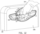
- the door 100 In the unlocked and latched state of the door latch 102, the door 100 is closed and a user may grasp and pull the combination of the handle base 14 and the grip cover 12 outwardly away from the door 100 to cause the latch actuator 16 to unlatch the door latch 102 so that the user may open the door 100, e.g., by continuing to pull outwardly on the combination of the handle base 14 and grip cover 12.
- the latch actuator 16 In the locked and latched state of the door latch 102, the latch actuator 16 is prevented from unlatching the door latch 102, thereby preventing the door 100 from being opened.
- Such operation of the latch actuator 16 and the door latch 102 is conventional.
- the sensors 46, 62 carried by the door handle assembly 10 illustratively provide for controlled locking and unlocking of the door latch 102 as just described.
- the sensor 46 illustratively provides for controlled unlocking of the door latch 102
- the sensor 62 illustratively provides for controlled locking of the door latch 102.
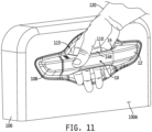
- the door latch 102 in its locked state may be unlocked by extending at least a portion of a hand 120 into the space 110 between the rear surface 14R of the rear wall 14G of the handle base 14 and the portion 115 of the outer skin 100A of the door 100.
- the senor 46 is illustratively configured to be triggered when the portion of the hand 120 is within a designed distance of, but not in contact with, the rear surface 14R. In alternate embodiments, the sensor 46 may be configured to be triggered when the portion of the hand 120 is in contact with the rear surface 14R of the rear wall 14G of the handle base 14. In any case, the output signal of the sensor 46 is monitored by the processor 104, under control of instructions stored in the memory 106, and such triggering of the sensor 46 creates a detectable change in the output signal of the sensor 46 to which the processor 104 is responsive to control the door latch 102 to its unlocked state. Thereafter, the door handle assembly 10 may be actuated as illustrated in FIG.
- the processor 104 may be additionally or alternatively responsive to triggering of the sensor 46 to control the door latch 102 to its unlatched state.
- the processor 104 may be additionally or alternatively responsive to triggering of the sensor 46 to control the door latch 102 to activate the door latch assembly 102 to automatically open the motor vehicle door.
- the door latch 102 in its unlocked state may be locked by applying a force or pressure, e.g., by a digit of a user's hand 120, to the portion 12K of the grip cover 12 sufficiently to cause the sensor 62 to be triggered as described above.
- the output signal of the sensor 62 is monitored by the processor 104, under control of instructions stored in the memory 106, and such triggering of the sensor 62 creates a detectable change in the output signal of the sensor 62 to which the processor 104 is responsive to control the door latch 102 to its locked state. Thereafter, the door latch 102 will prevent actuation of the door handle assembly 10 from causing the latch actuator 16 to unlatch the door latch 102.
- the processor 104 may be additionally or alternatively responsive to triggering of the sensor 62 to control the door latch 102 to its latched state.
- the door latch assembly 102 is or includes an automatic door opening/closing/assist apparatus and the motor vehicle door is provided in the form of an access closure with power open/close assist features, e.g., such as a power lift gate, a power rear door, a power side door, a power sliding door or the like
- the processor 104 may be additionally or alternatively responsive to triggering of the sensor 62 to control the door latch 102 to activate the door latch assembly 102 to automatically close the motor vehicle door.
- triggering of at least one of the sensors 46, 62 may cause the processor 104 to control other aspects of the door handle assembly 10.
- the circuit board 40, the circuit board carrier 30, the handle base 14 and/or the grip cover 12 may have one or more illumination sources mounted thereto, and in such embodiments the instructions stored in the memory 106 may include instructions which, when executed by the processor 104, cause the processor 104 to activate one or more such illumination sources in response to detected trigger of either or both of the sensors 46, 62.
- the processor 104 may be programmed to control the state of the door latch 12 based on sequential triggering of at least one of the sensors 46, 62 according to a predefined or programmable triggering sequence.
- the instructions stored in the memory 106 may include instructions which, when executed by the processor 104, cause the processor 104 to control the door latch 102 from its locked state to its unlocked state (and/or to control the door latch 102 from its latched state to its unlatched state and/or to control the door latch 102 to automatically open the vehicle door) upon detection of the sensor triggering sequence 2212.
- the sensor triggering sequence may be a predefined sequence
- the instructions stored in the memory 106 may include instructions which, when executed by the processor 104, cause the processor 104 to execute a programming mode in which a "private" triggering sequence may be programmed by a user.
- different users of the vehicle may program different private triggering sequences and in such embodiments the processor 104 may be configured to control the door latch 102 from its locked state to its unlocked state upon detection of any such programmed triggering sequence.
- the processor 104 may be programmed in some such embodiments to control the door latch 102 from its unlocked state to its locked state (and/or to control the door latch 102 from its unlatched state to its latched state and/or to control the door latch 102 to automatically close the vehicle door) upon detection of a single triggering of the sensor 62 as described above, or upon detection of a predefined or programmed sequence of sensor trigger events of either one or both of the sensors 46, 62 as just described.
- triggering of at least one of the sensors 46, 62 may cause the processor 104 to control other aspects of the motor vehicle as described briefly above.
- the processor 104 (and/or the processor carried on the circuit board 40, if any) may be configured to process a single trigger signal or a sequence of trigger signals produced by either or both of the sensors, e.g., the sensors 46, 62, and/or other or additional sensors carried by the assembly 10, to selectively control, i.e., activate, deactivate, select or control one or more actuators, devices or systems 107 to thereby activate, deactivate, select, control and/or position one or more driver and/or passenger settings of the motor vehicle.
- Examples of such one or more inter-vehicle driver and/or passenger settings of the motor vehicle may include, but are not limited to, one or more interior light settings, one or more entertainment system settings, one or more climate control settings, one or more seat position settings, one or more steering wheel position settings, one or more rear view mirror position settings, one or more side mirror position settings, one or more window and/or sunroof position settings, and/or the like.
- Examples of such one or more external vehicle driver and/or passenger settings of the motor vehicle may include, but are not limited to, one or more exterior structures and/or features of motor vehicle when the vehicle is parked/stationary such as a position of one or more of motor vehicle side mirrors, e.g., folded against the motor vehicle or unfolded to an operative position, one or more window and/or sunroof position settings, one or more external motor vehicle lights, or the like.
- door handle assembly 10 has been described as including two sensors mounted separately from one another, this disclosure contemplates embodiments in which both sensors are mounted together, e.g., on one or more substrates mounted to a sensor cartridge received in a slot formed in the grip cover 12 which extends the length, or at least part of the length, of the internal space 12S thereof, on one or more substrates mounted directly to the grip cover 12, or on one or more substrates mounted to the handle base 14.
- both sensors are mounted together, e.g., on one or more substrates mounted to a sensor cartridge received in a slot formed in the grip cover 12 which extends the length, or at least part of the length, of the internal space 12S thereof, on one or more substrates mounted directly to the grip cover 12, or on one or more substrates mounted to the handle base 14.
- FIGS the door handle assembly 10 is illustrated in FIGS.
- the door handle assembly may alternatively be mounted, in whole or in part, to other structures of the motor vehicle including, for example, but not limited to, a sliding motor vehicle door, a rear hatch, trunk or swinging door of the motor vehicle or a stationary portion of the motor vehicle such as, any of the so-called "A,”"B” or "C” pillars of the motor vehicle.
Landscapes
- Physics & Mathematics (AREA)
- General Physics & Mathematics (AREA)
- Lock And Its Accessories (AREA)
Description
- The present invention relates generally to door handle assemblies for motor vehicles, and more specifically to door handle assemblies including sensor- based control features.
- Door handle assemblies for motor vehicles which include keyless entry features are generally known. It is desirable to provide improved door handle assemblies with one or more sensor-based control features.
-
US 2006/0226953 A2 refers to a passive entry sensor system that includes an optical sensor mounted directly in an end of a door handle assembly and a reflector located at an opposing end of the handle facing the sensor. The optical sensor is adapted to transmit an IR beam at an angle along the length of the handle to the reflector and to detect the IR beam reflected back by the reflector. The sensor includes signal processor circuitry which detects an interruption or modification of the beam and, anticipating a pull of the door, provides an output control signal to a control module which generates an RF signal for interrogating a user's digital ID on a card. When a user's head ID matches a stored digital ID, a control signal is generated by a processor in the control module to unlock a locking mechanism and allows the door to open. -
EP 1 760 227 A1 -
EP 1 910 631 A1 -
EP 2 458 119 A2 refers to a door handle that includes a first handle case and a second handle case. The first handle case includes an unlock detection electrode of an electrostatic capacity sensor detecting, on the basis of a fluctuation of the electrostatic capacity, a door-unlock command of a vehicle. Another door handle further includes a conductive plate fixedly adhered to a front end portion of a double faced adhesive tape at a portion that faces a lock detection electrode via a handle case. A decorating piece having a band shape is fixedly adhered to the double faced adhesive tape at which the conductive plate is provided, along the full length of the double faced adhesive tape in the longitudinal direction thereof. -
EP 2 088 267 A2 discloses a motor vehicle door handle with a manually actuated sensor assembly in its wall. The arrangement has a sensor section at an outer side of a wall section of a wall. The wall encloses electrical components and another sensor section, i.e. Hall sensor, and is insulated against the environment. The former sensor section has a deformable mechanical element, i.e. snapping panel, with stable resting and metastable states, and the element is arranged in a recess of the wall. An abrupt transition in a metastable state leads to a tactile feedback signal, which is tangible to a user. The transition is caused by a manual force effect on an outer side of the element. -
DE 10 2016 112423 A1 -
US 2005/057047 A1 discloses a motor vehicle door locking system and a door handle. In order to prevent unlocking or opening of an electrically triggered motor vehicle door lock by unintentional actuation of a first actuating means, a second actuating means is employed and required to be activated in combination with the first actuation means for unlocking or opening of the motor vehicle door lock, and thus unlocking or opening the assigned motor vehicle. - The present invention provides a door handle assembly as defined in
claim 1. Preferred embodiments are defined by the dependent claims. - A door handle assembly is provided for a motor vehicle door having a latch controllable between a latched condition in which the door is prevented from opening and an unlatched condition in which the door is not prevented from opening. In accordance with the invention, the door handle assembly comprises a handle base configured to be secured to a door of the motor vehicle and configured to operatively couple to the latch for controlling the latch, the handle base having a first surface spaced apart from and generally facing the door and a second surface opposite the first surface thereof, the handle base defining a first detection surface along at least a portion of the first surface of the handle base,a grip cover having a first surface and a second surface opposite the first surface thereof, the grip cover coupled to the handle base with the first surface of the grip cover facing the second surface of the handle base such that the first surface of the handle base and the second surface of the grip cover cooperatively define a door handle grip, wherein a portion of the grip cover is at least partially flexible so as to deflect toward the handle base upon application of pressure to the second surface of the portion of the grip cover, the second surface of the portion of the grip cover defining a second detection surface, a first sensor configured to produce a first sensor signal, the first sensor mounted to the handle base and positioned relative to the handle base opposite the first detection surface of the handle base, the first sensor being configured to produce a detectable change in the first sensor signal upon detection of one of an object within a detection proximity of the first detection surface and deflection of the portion of the handle base defining the first detection surface to within a detection proximity of a sensing surface of the first sensor, the detectable change in the first sensor signal enabling the latch to unlock or unlatch, an electrically conductive layer disposed on the first surface of the portion of the grip cover opposite the second detection surface.
- The door handle assembly further comprises a second sensor configured to produce a second sensor signal, the second sensor being an inductive proximity sensor mounted within the grip cover such that a sensing surface of the inductive proximity sensor is spaced apart from the electrically conductive layer, the inductive proximity sensor configured to produce a detectable change in the second sensor signal in the form of a detectable change in an electromagnetic field produced by the inductive proximity sensor upon detection of deflection of the portion of the grip cover defining the second detection surface to within a detection proximity of the sensing surface of the second sensor, the detectable change in the second sensor signal enabling the latch to lock or latch.
- This invention is illustrated by way of example and not by way of limitation in the accompanying Figures. Where considered appropriate, reference labels have been repeated among the Figures to indicate corresponding or analogous elements.
-
FIG. 1 is a front perspective view of an embodiment of a door handle assembly. -
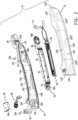
FIG. 2 is a front perspective exploded view of the door handle assembly depicted inFIG. 1 . -
FIG. 3 is a perspective view of a circuit board subassembly of the door handle assembly ofFIG. 2 in which the circuit board is mounted to the circuit board carrier and the sensor cartridge assembly is electrically connected to the circuit board. -
FIG. 4 is a perspective view of the sensor assembly illustrated inFIGS 2 and3 . -
FIG. 5 is a perspective view of the sensor cartridge illustrated inFIGS. 2 and3 . -
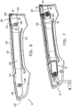
FIG. 6 is a rear perspective view of the grip cover depicted inFIGS. 1 and2 . -
FIG. 7 is a rear perspective view similar toFIG. 6 and further illustrating mounting therein of the circuit board subassembly. -
FIG. 8A is a magnified view of a portion of the rear side of the grip cover illustrating mounting of the sensor cartridge assembly thereto. -
FIG. 8B is a magnified view similar toFIG. 8A but with the sensor cartridge omitted to illustrate positioning of the sensor relative to the grip cover. -
FIG. 9 is a cross-sectional view of the handle base ofFIG. 1 as viewed along section lines 9-9 and with the grip cover omitted to illustrate an embodiment of a sensor positioned adjacent to the rear surface of the handle base. -
FIG. 10 is a front perspective and partial cutaway view of the door handle assembly ofFIGS. 1-9 shown mounted to a door of a motor vehicle and operatively connected to a door latch and processor of the motor vehicle. -
FIG. 11 is a front perspective view of the door handle assembly ofFIGS. 1-9 mounted to a door of a motor vehicle, shown with a portion of a hand inserted between the door and the door handle assembly which causes a detectable change in the output of one of the sensors carried by the door handle assembly. -
FIG. 12 is a front perspective view similar toFIG. 11 showing the hand exerting an outward force against the door handle assembly to actuate the door latch actuator and open the door of the motor vehicle. -
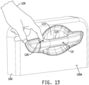
FIG. 13 is a front perspective view similar toFIGS. 11 and12 showing exertion of a force or pressure against a portion of the grip cover which causes a detectable change in the electrical output of another of the sensors carried by the door handle assembly. - While the present invention is susceptible to various modifications and alternative forms, specific exemplary embodiments thereof have been shown by way of example in the drawing and will herein be described in detail. It should be understood, however, that there is no intent to limit the present invention to the particular forms disclosed, but on the contrary, the intention is to cover all modifications, equivalents, and alternatives consistent with the present invention as defined by the appended claims.
- References in the specification to "one embodiment", "an embodiment", "an example embodiment", etc., indicate that the embodiment described may include a particular feature, structure, or characteristic, but every embodiment may not necessarily include the particular feature, structure, or characteristic. Moreover, such phrases may or may not necessarily refer to the same embodiment. Further, when a particular feature, structure or characteristic is described in connection with an embodiment, it is submitted that it is within the knowledge of one skilled in the art to effect such feature, structure or characteristic in connection with other embodiments whether or not explicitly described. Further still, it is contemplated that any single feature, structure or characteristic disclosed herein may be combined with any one or more other disclosed feature, structure or characteristic, whether or not explicitly described, and that no limitations on the types and/or number of such combinations should therefore be inferred.
- Referring now to
FIG. 1 , an embodiment is shown of adoor handle assembly 10 for a motor vehicle. Thedoor handle assembly 10 illustratively includes agrip cover 12 that mates with ahandle base 14. Thehandle base 14 illustratively includes apivot mount 18 configured to be pivotally mounted to an entry door of a motor vehicle and alatch actuator 16 operatively coupled with a door latch assembly located within the entry door. Together, thegrip cover 12 and thehandle base 14 form a grip configured to be grasped by a human hand. As will be described in greater detail below, thegrip cover 12 and handlebase 14 together form a housing which carries two sensors; one which may be triggered or otherwise activated to cause a door latch of the entry door to lock and thereby prevent manual actuation of thehandle assembly 10 to open the entry door and/or to latch thehandle assembly 10 to the entry door, and another which may be triggered or otherwise activated to cause the door latch of the entry door to unlock or unlatch so that thedoor handle assembly 10 may be manually actuated in a conventional manner to open the entry door. - In the illustrated embodiment, the
grip cover 12 comprises opposing upper andlower walls side walls such walls 12A - 12D are joined by an elongated andfront wall 12E which may be at least partially arcuate. Between theside walls lower walls grip cover 12 define arear lip 12F which illustratively defines an arcuate and generally concave section 12I between and relative to twoopposing end sections FIG. 6 ). Between therear lip 12F and interior surfaces of the upper andlower walls side walls rear surface 12J of thefront wall 12E, thegrip cover 12 defines an internal or interior space 12S. In one embodiment, thegrip cover 12 is of uniform construction, although in other embodiments thegrip cover 12 may be formed by securing together two or more component parts. The grip cover 12 may be formed of one or more conventional materials, and in one embodiment thegrip cover 12 is a plastic component covered by a metallic film or coating to simulate a chrome handle. Alternatively or additionally, theplastic grip cover 12 may be covered by one or more colored films or coatings and/or by one or more clear films or coatings. In still other embodiments, thegrip cover 12 may be formed of or include one or more coated or uncoated metals or metal composites. - The
handle base 14 illustratively has opposing upper andlower walls 14A, 14B respectively and opposingside walls 14C, 14D respectively. Allsuch walls 14A - 14D are joined by an elongated rear wall 14G which is illustratively at least partially arcuate to match the at least partially arcuate shape of thefront wall 12E of thegrip cover 12. Between theside walls 14C, 14D, the upper andlower walls 14A, 14B of thehandle base 14 define afront lip 14L which illustratively defines an arcuate and generally concave section between and relative to two opposing end sections configured to match the concave section 12I andend sections grip cover 12 such that thefront lip 14L of thehandle base 14 receives in contact therear lip 12F of thegrip cover 12 when thegrip cover 12 and thehandle base 14 are brought together as illustrated inFIG. 1 . Between thefront lip 14L and interior surfaces of the upper andlower walls 14A, 14B, theside walls 14C, 14D and thefront surface 14H of the rear wall 114G, thehandle base 14 defines an internal or interior space 14S. - A
latch actuator 16 extends rearwardly from thehandle base 14 adjacent to one of theside walls 14C, and apivot mount 18 extends rearwardly from thehandle base 14 adjacent to the opposite side wall 14D. Thelatch actuator 16 is illustratively configured to operatively couple to a conventional door latch assembly carried by a door of a motor vehicle to which thehandle assembly 10 is mounted (see, e.g.,FIG. 10 ). Thepivot mount 18 is illustratively configured to extend into the door and pivotally couple to one or more structures therein. Movement of thehandle base 14 about thepivot mount 18 illustratively moves thelatch actuator 16 to actuate the door latch assembly in a conventional manner to enable the user to open the motor vehicle door. Two bores 20A, 20B are formed through thehandle base 14; onebore 20A is formed adjacent to thelatch actuator 16 and theother bore 20B is formed adjacent to thepivot mount 18. - Adjacent to the
latch actuator 16, thehandle base 14 defines aprotrusion 14E between the upper andlower walls 14A, 14B, and adjacent to thepivot mount 18 the handle base defines aprotrusion 14F between the upper andlower walls 14A, 14B. Eachprotrusion handle base 14, and the arcuate rear wall 14G extends between theprotrusions lower walls 14A, 14B. As illustrated most clearly inFIGS. 10 - 13 , theprotrusions handle base 14 are illustratively sized and configured to contact theouter skin 100A of themotor vehicle door 100 when thedoor assembly 10 is mounted to themotor vehicle door 100, and aspace 110 is defined between aportion 115 of the outer surface of theouter skin 100A of thedoor 100 and therear surface 14R of the arcuate rear wall 14G of thehandle base 14. The arcuate profile of the rear wall 14G of thehandle base 14 is, along with sizes and shapes of theprotrusions space 110 with a size and shape suitable to allow one or more fingers and at least a portion of ahuman hand 120 to extend sufficiently therein to come into contact with therear surface 14R of the rear wall 14G so that thehand 120 can then grasp the combination of thehandle base 14 and thegrip cover 12 with at least one finger extending into thespace 110 and wrapped around therear surface 14R of the arcuate rear wall 14G of thehandle base 14 in a conventional fashion. - In one embodiment the
handle base 14 is of uniform construction, although in other embodiments thehandle base 14 may be formed by securing together two or more component parts. Thehandle base 14 may be formed of one or more conventional materials, and in one embodiment thehandle base 14 is a plastic component covered by one or more suitable films or coatings. In alternate embodiments, thehandle base 14 may be formed of or include one or more other suitable coated or uncoated materials. - The interior space 12S of the
grip cover 12 and the interior space 14S of thehandle base 14 together define a space sized to house electronic components when thegrip cover 12 and thehandle base 14 are secured together. Referring now toFIG. 2 , thedoor handle assembly 10 illustratively further includes acircuit board carrier 30 to which acircuit board 40 is mounted, and thecircuit board carrier 30 andcircuit board 40 are together mounted within the space defined by and between the interior spaces 12S and 14S of thegrip cover 12 and thehandle base 14 respectively. Asensor cartridge 50 is received within thegrip cover 12 separately from thecircuit board carrier 30 and thecircuit board 40, and asensor assembly 60, including a sensor 62 (see alsoFIG. 4 ), mountable to thesensor cartridge 50 is electrically connectable to thecircuit board 40. In the illustrated embodiment, and as will be described in greater detail below, thesensor assembly 60 is mounted to thesensor cartridge 50, and thesensor cartridge 50 is then mounted to thegrip cover 12 such that the sensing surface of thesensor 62 is operatively spaced apart from asensor triggering portion 12K of thegrip cover 12. In some embodiments, thesensor triggering portion 12K of thegrip cover 12K is configured to be visually identifiable with the naked eye. In other embodiments, thesensor triggering portion 12K may be visually identified via an illumination source carried within thegrip cover 12. Although thesensor triggering portion 12K is illustrated inFIGS. 1 and2 as being a portion of theupper wall 12A of thegrip cover 12 adjacent to theside wall 12C, it will be understood that thesensor triggering portion 12K may alternatively be located anywhere along theupper wall 12A, e.g., such as thealternate portion 12K' of thetop wall 12A adjacent to theside wall 12D as illustrated by dashed-line configuration inFIG. 2 , or anywhere along thefront wall 12E, e.g., such as thealternate portion 12K" of thefront wall 12E adjacent to theside wall 12C, thealternate portion 12K‴ adjacent to theside wall 12D or thealternate portion 12KIV of thefront wall 12E centrally between theside walls FIG. 2 . In any such alternate positioning of thesensor triggering portion 12K', 12K", 12K‴, 12KIV of thegrip cover 12, it will be further understood that thesensor cartridge 50 andsensor 60 assembly will be suitably mounted to thegrip cover 12 to position the sensing surface of thesensor 62 so as to be operatively spaced apart from thewall portion 12K', 12K", 12K‴, 12KIV. In some embodiments, as will be described below, thesensor triggering portion sensor triggering portion sensor trigger portion grip cover 12 by embossing, etching, e.g., laser etching, molding, machining or otherwise altering the physical appearance of thesensor trigger portion grip cover 12, and/or by configuring thesensor trigger portion grip cover 12 can be seen on and/or externally to thesensor trigger portion - The
circuit board 40 illustratively has a number of electronic circuit components mounted thereto. Such electronic circuit components illustratively include another sensor (one example 46 of which is illustrated inFIG. 9 ), sensor signal conditioning circuitry in the form of at least one conventional sensorsignal processing circuit 45 configured to process sensor signals produced by at least one of thesensors circuit board 40 may be or include a conventional processor configured to execute instructions stored in an on-board and/or externally connected memory unit. In embodiments which include such a processor, the on-board and/or externally connected memory unit illustratively has instructions stored therein which, when executed by the processor, cause it to produce control signals to control one or more features associated with thedoor handle assembly 10. In other embodiments, e.g., as illustrated by example inFIG. 10 , such aprocessor 104 andmemory 106 may both be located outside of thedoor handle assembly 10, e.g., within thedoor 100 or other area of a motor vehicle, and electrically connected to thecircuit board 40 viasuitable wiring 44. In either case, such features may include, but are not necessarily limited to, locking and unlocking of thedoor handle assembly 10. Alternatively or additionally, such features may include unlatching of thedoor handle assembly 10, i.e., controlling thelatch actuator 16 and/or adoor latch assembly 102 of the motor vehicle to automatically uncouple thelatch actuator 16 from thedoor latch assembly 102, latching of thedoor handle assembly 10, i.e., controlling thelatch actuator 16 and/or adoor latch assembly 102 of the motor vehicle to automatically couple thelatch actuator 16 to thedoor latch assembly 102, activating and/or deactivating thedoor latch assembly 102 to automatically close and/or open the motor vehicle door in embodiments in which thedoor latch assembly 102 is or includes an automatic door opening/closing/assist apparatus and the motor vehicle door is provided in the form of an access closure with power open/close assist features, e.g., such as a power lift gate, a power rear door, a power side door, a power sliding door or the like. Alternatively or additionally still, in embodiments in which one or more illumination sources is/are mounted to thecircuit board 40 and/or elsewhere on or within thedoor handle assembly 10, such features may include selectively illuminating one or more portions of thedoor handle assembly 10 and/or one or more portions of themotor vehicle door 100 to which thedoor handle assembly 10 is mounted. Alternatively or additionally still, such one or more features may include processing a sequence of detectable changes in signals produced by either or both of the sensors, e.g., thesensors assembly 10, and comparing such a sequence to a predefined or pre-set sequence for the purpose of determining whether to lock, unlock, latch, unlatch, close and/or open thedoor handle assembly 10. Alternatively or additionally still, such one or more features may include processing a sequence of detectable changes in signals produced by either or both of the sensors, e.g., thesensors assembly 10, to selectively control, i.e., activate, deactivate, select and/or position, one or more driver and/or passenger settings within motor vehicle, e.g., one or more interior light settings, one or more entertainment system settings, one or more climate control settings, one or more seat position settings, one or more steering wheel position settings, one or more rear view mirror position settings, one or more side mirror position settings, one or more window and/or sunroof position settings, and/or the like. Alternatively or additionally still, such one or more features may include processing a sequence of detectable changes in signals produced by either or both of the sensors, e.g., thesensors assembly 10, to selectively control, i.e., activate, deactivate, select and/or position, one or more exterior structures and/or features of motor vehicle when the vehicle is parked/stationary, e.g., a position of one or more of motor vehicle side mirrors, e.g., folded against the motor vehicle or unfolded to an operative position, one or more window and/or sunroof position settings, one or more external motor vehicle lights, or the like. - The
circuit board carrier 30 illustratively has arear wall 32 from which top and bottom flanges forwardly extend to form apocket 35 sized and configured to receive thecircuit board 40 therein as depicted inFIG. 3 . At one end of thepocket 35, thecircuit board carrier 30 defines aslot 34 sized and configured to receive therein awiring block 64 associated with the sensor assembly 60 (seeFIG. 4 ), and at an opposite end of thepocket 35 thecircuit board carrier 30 defines anotherslot 36 sized and configured to receive therein anotherwiring block 42 which supports and isolates thewiring 44 electrically connected to the electronic circuitry carried by thecircuit board 40. Thewiring 44 is illustratively fed externally from thedoor handle assembly 10 through anopening 25 defined through thehandle base 14. Abore 38A is formed through thecircuit board carrier 30 between theslot 34 and one end thereof, and anotherbore 38B is formed through thecircuit board carrier 30 between theslot 36 and an opposite end thereof. Thebores bores handle base 40, andconventional fixation members FIG. 1 ) to mount thecircuit board carrier 30 to thehandle base 14. - Referring now to
FIG. 3 , thecircuit board 40 is shown mounted to thecircuit board carrier 30 to form acircuit board subassembly 70. In the illustrated embodiment, thecircuit board 40 is received within thepocket 35 of thecircuit board carrier 30 with thewiring block 42 electrically connected to thecircuit board 40 and to thewiring 44 received within theslot 36. Also shown inFIG. 3 is thesensor 62 of thesensor assembly 60 mounted to and within thesensor cartridge 50 to form asensor cartridge assembly 80, and thewiring block 64 associated with thesensor assembly 62 received within theslot 34 of the circuit board carrier. - As illustrated by example in
FIG. 4 , thesensor assembly 60 includes asensor 62 in the form of an inductive sensor. Thesensor 62 includes aplanar substrate 63 having aplanar sensor surface 63A upon which asensor coil 65 is disposed and electrically connected to twowires wires sensor coil 65 passes successively through a pair of wiring blocks 66 and 64 respectively configured to support thewires sensor carrier 50 is illustrated inFIG. 5 and includes aplanar member 52 defining a planartop surface 50A (seeFIG. 1 ) and a bottomplanar surface 50B, opposite the topplanar surface 50A, from which surrounding sidewalls 55A-55D extend normally away. A pair of spaced apart interior sidewalls 56A, 56B extend normally away from the bottomplanar surface 50B of theplanar member 52 adjacent to the sidewall 55D which is also formed of spaced apart walls to form aslot 54 through thewalls wiring block 66 therein. Aflange 57A extends away from one side of theplanar member 52 adjacent and generally normal to thesidewall 55B, and anotherflange 57B extends away from an opposite side of theplanar member 52 adjacent and generally normal to the sidewall 55D. Theflanges bottom surfaces planar member 52. A pair ofprotrusions flange 57A, and a pair ofprotrusions flange 57B. - As illustrated in
FIG. 3 , thesensor 62 is received and mounted within the pocket formed between theplanar member 52 and thesidewalls 55A-55D of thesensor cartridge 50 such that thesensor surface 63A of thesensor substrate 63 faces the bottomplanar surface 50B of theplanar member 52. Thewiring block 66 is received within theslot 54 formed between the sidewalls 55D, 56A, 56B with thewires sensor carrier 50 to secure thesensor 62 therein. In any case, thesensor 62 is carried within the pocket of the sensor cartridge with theplanar sensor surface 63A of thesensor substrate 63 spaced apart from and generally parallel with the planartop surface 50A of thesensor cartridge 50. - With the
sensor 62 positioned within thesensor cartridge 50 as illustrated inFIG. 3 , thewiring block 64 of thesensor assembly 60 is positioned in theslot 34 defined by thecircuit board carrier 30, and thewires wiring block 64 are electrically connected to correspondingelectrical terminals circuit board 40 and electrically coupled to one or more electronic components carried by thecircuit board 40. The wiring blocks 64, 66 support thesensor wires wires circuit board carrier 30 and thesensor cartridge 50 respectively. - Referring now to
FIG. 6 , the back or rear side of thegrip cover 12 is shown in which therear surface 12J of thefront wall 12E defines a pair of spaced apartreceptacles fixation members FIG. 1 . As illustrated by example inFIG. 7 , the spaced apartreceptacles bores circuit board carrier 30 such that thefixation members circuit board assembly 70 to thegrip cover 12. It will be understood that thefixation members handle base 14 to thegrip cover 12 with thecircuit board subassembly 70 mounted therebetween in the space defined by the interior spaces 12S, 14S of the two components, and that thehandle base 14 is omitted inFIG. 7 to illustrate attachment of thecircuit board assembly 70 to thegrip cover 12. - As further illustrated in
FIGS. 6-8B , the interior space 12S of thegrip cover 12 defines aslot 90 sized and configured to receive thesensor cartridge 50 of thesensor cartridge assembly 80 therein. Theslot 90 is illustratively defined adjacent to theside wall 12C of thegrip cover 12 and is bordered along its top by a generallyplanar portion 12L of the inner surface of thetop wall 12A of thegrip cover 12. Theportion 12L of the inner surface of thetop wall 12A is defined opposite thesensor triggering portion 12K between opposingears top wall 12A of thegrip cover 12 into the space 12S. Theslot 90 defined between theinner surface 12L of thegrip cover 12 and the opposingears sensor cartridge 50 therein with theslot 54 of thesensor cartridge 50 and thewiring block 64 received therein facing away from theside wall 12C so as to direct thewires circuit board 40. As most clearly illustrated inFIGS. 8A and8B , theprojections planar surface 50A of thesensor cartridge 50, and thus theplanar sensing surface 63A of thesensor substrate 63, spaced apart from and generally parallel with theplanar portion 12L of the inner surface of thetop wall 12A of thegrip cover 12. As illustrated inFIG. 8A , with thesensor cartridge 50 positioned in theslot 90, aspace 96A is defined between theportion 12L of the inner surface of thetop wall 12A and the topplanar surface 50A of thesensor cartridge 50 which, in turn, defines aspace 96B between theportion 12L of the inner surface of thetop wall 12A and theplanar sensing surface 63A of thesensor substrate 63 on which thesensor coil 65 is disposed as illustrated inFIG. 8B . - As further illustrated in
FIG. 8B , an electrically conductive film, layer orplate 98 is secured to theportion 12L of the inner surface of thetop wall 12A so as to be positioned opposite and spaced apart from thesensor coil 65 disposed on theplanar sensing surface 63A of thesensor substrate 63 when thesensor cartridge 50 carrying thesensor 62 is received within theslot 90. Examples of the conductive film, layer orplate 98 may include, but are not limited to, any metallic or other electrically conductive film, e.g., chrome or other material(s), painted, deposited or otherwise formed on theportion 12L of the inner surface of thetop wall 12A of thegrip cover 12, a tape having one or more electrically conductive layers and/or particles affixed thereto or embedded therein and one or more bonding media, e.g., adhesive or other bonding media, applied thereto for affixing the tape to theportion 12L of the inner surface of thetop wall 12A, one or more rigid or semi-rigid electrically conductive sheets or plates affixed in any manner to theportion 12L of the inner surface of thetop wall 12A, or the like. - In the illustrated embodiment, at least the portion of the
top wall 12A defining thesensor triggering portion 12K is made to be at least partially flexible such that theportion 12L of the inner surface of thetop wall 12A is displaced inwardly toward thesensor coil 65 in response to pressure or force applied to thesensor triggering portion 12K of thetop wall 12A by, e.g., a digit of a human hand. Operation of theinductive sensor 62 is conventional in that thesensor coil 65 is energized by circuitry on thecircuit board 40 to create a sensor output signal in the form of an electromagnetic field adjacent to theplanar sensing surface 63A of thesensor substrate 63. In one example embodiment, circuitry on thecircuit board 40 includes a capacitive component electrically connected to thesensor coil 65 through thewires sensor coil 65 together form a resonant circuit. In some embodiments, the resonant circuit may include at least one or more additional passive components such as one or more resistive elements, although in other embodiments the resistive element of the resonant circuit may be provided in the form of inherent resistance in either or both of the capacitive component and thesensor coil 65. In any case, a time-varying signal is applied to the resonant circuit to produce a time-varying electromagnetic field. The size of thesensor coil 65 and the strength of the electromagnetic field established by the energizedsensor coil 65 are selected such that the time-varying electromagnetic field extends across thespace 96B to the electrically conductive film orplate 98. When theportion 12L of the inner surface of thetop wall 12A of thegrip cover 12 deflects inwardly a sufficient distance relative to the surrounding portions of thegrip cover 12 in response to corresponding external pressure or force applied to theportion 12L of thetop wall 12A, the electrically conductive film orplate 98 is displaced to within a detection proximity of thesensor coil 65. This results in a measurable loss in the resonant circuit which can be measured as a detectable change in the output signal of thesensor 62. In one embodiment, this detectable change in the output signal of thesensor 62 is measured as a change in frequency over time, although in alternate embodiments the detectable change in the output signal of thesensor 62 may be measured as a change over time in capacitance, inductance and/or resistance, e.g., relative to reference components onboard thecircuit board 40. In some alternate embodiments, thesensor 62 may illustratively be affixed to or formed on, e.g., printed on, theportion 12L of thetop wall 12A of thegrip cover 12, and the electrically conductive film, layer orplate 98 may be affixed to or formed on thecarrier 50. In any case, thesensor 62 may, in some embodiments, be configured to be responsive to different magnitudes or levels of pressure applied to theportion grip cover 12 to produce distinguishably different sensor output signal magnitudes, and in some such embodiments different pressure(s) applied to theportion grip cover 12 may result in different functions carried out by thedoor handle assembly 10 and/or by one or more actuators or systems of the motor vehicle. - The mounting arrangement of the
sensor cartridge 50 to and within thegrip cover 12 as just described is illustratively implemented to minimize or at least reduce the possibility of unintended or "false" triggering of thesensor 62 due to movement of thegrip cover 12 relative to the structure(s) to which thesensor 62 may otherwise be mounted. In particular, mounting thesensor cartridge 50 carrying thesensor 62 to thegrip cover 12 as just described causes thesensor cartridge 50, and thus thesensor 62, to move along with any movement generally of thegrip cover 12. As long as any such movement of thegrip cover 12 does not cause deflection of thesensor triggering portion 12L relative to surrounding portions of thegrip cover 12, no detectable change in the output signal of thesensor coil 65 will occur. It is only when thesensor triggering portion 12L deflects inwardly relative to the surrounding portions of thegrip cover 12 by an amount sufficient to cause a detectable change in the output signal of thesensor coil 65 that triggering of thesensor 62 will occur as described above. If thesensor 62 is otherwise mounted to thehandle base 14, thecircuit board carrier 30 or thecircuit board 40 and the electrically conductive film orplate 98 is secured to a portion of thegrip cover 12 opposite thesensor 62, any movement of any portion of thegrip cover 12 that causes the film orplate 98 to move sufficiently toward or away from thesensor 62 may result in unintended and thus "false" triggering of thesensor 62. Such "false" triggering of thesensor 62 may be more likely if thesensor 62 is not mounted to thegrip cover 12 as described above. - Referring now to
FIG. 9 , anothersensor 46 is illustratively carried by thedoor handle assembly 10 and is configured to detect objects proximate to or in contact with therear surface 14R of the arcuate rear wall 14G of thehandle base 14. In the illustrated embodiment, such asensor 46 is illustratively provided in the form of an electrically conductive film, coating orplate 47 facing thefront surface 14H of the rear wall 14G of thehandle base 14 and electrically connected to circuitry carried by thecircuit board 40. In the illustrated embodiment, the film, coating orplate 47 is affixed to the bottom surface of thecircuit board 40, although in alternate embodiments the film, coating orplate 47 may be or be affixed to the front or rear surface of therear wall 32 of thecircuit board carrier 30, and in still other embodiments the film, coating orplate 47 may be or be affixed to thefront surface 14H of thehandle base 14 or otherwise disposed so as to be suitably spaced apart from therear surface 14R of thehandle base 14. In any case, the film, coating orplate 47 may be provided in any of the forms described by example above with respect to the electrically conductive film, layer orplate 98, wherein any such film, coating, layer or plate material is electrically connected to circuitry carried by thecircuit board 40 as described below. - The film, coating or
plate 47 electrically connected to circuitry carried by thecircuit board 40 forms one electrode of aconventional capacitive sensor 46. In the illustrated embodiment, portions of therear wall 32 of thecircuit board carrier 30 and the rear wall 14G of thehandle base 14 aligned with outwardly facingsurface 47A of the film, coating orplate 47 together form a dielectric of the capacitive sensor, and circuitry on-board thecircuit board 40 applies a time-varying, e.g., AC signal, to the film, coating orplate 47 which causes the film, coating orplate 47 to create a time-varying electric field. As long as no object is placed sufficiently close to therear surface 14R of the rear wall 14G of thehandle base 14, the time-varying electric field will not measurably change. Placing an object sufficiently close to therear surface 14R of the rear wall 14G will induce a change the electric field produced by the film, coating orplate 47 which can be measured as a detectable change in the output signal of thesensor 46. In one embodiment, this detectable change in the output signal of thesensor 46 is measured as a change in voltage over time, although in alternate embodiments the detectable change in the output signal of thesensor 46 may be measured as a change over time in current or as a change over time in capacitance, e.g., relative to a reference capacitor onboard thecircuit board 40. In one embodiment, the size of the film, coating orplate 47, the amplitude of the time-varying applied thereto, the thickness of the dielectric materials and the dielectric constant of the combined dielectric materials are illustratively selected so that at least a portion of a human hand, e.g., one or more fingers, within a detection proximity of therear surface 14R of the rear wall 14G of thehandle base 14 will trigger thesensor 46. In alternate embodiments, such parameters may be selected so that at least a portion of a human hand must be in contact with therear surface 14R of the rear wall 14G in order to trigger thesensor 46. In any case, thesensor 46 may, in some embodiments, be configured to be responsive to different distances of the object, e.g., fingers and/or hand, from therear surface 14R of the rear wall 14G of thehandle base 14 to produce distinguishably different sensor output signal magnitudes, and in some such embodiments such different distances of the object from therear surface 14R of thehandle base 14 may result in different functions carried out by thedoor handle assembly 10 and/or by one or more actuators or systems of the motor vehicle. - Referring now to
FIG. 10 , thedoor handle assembly 10 is shown mounted to anentry door 100 of a motor vehicle. In the illustrated embodiment, thelatch actuator 16 extends through theouter skin 100A of thevehicle door 100 and is mechanically linked via a linkage L to aconventional door latch 102 of thevehicle door 100. A door lock and unlock (and/or door latch/unlatch)actuator 105 is coupled to thedoor latch 102. The door lock and unlockactuator 105 is responsive to a lock signal to lock thedoor latch 102 and to an unlock signal to unlock the door latch 102 (and/or to a latch signal to latch thedoor latch 102 and/or to an unlatch signal to unlatch the door latch 102). In the embodiment illustrated inFIG. 10 , thewiring 44 connected to thecircuit board 40 of thedoor handle assembly 10 is electrically connected to aprocessor 104 located within the motor vehicle, e.g., as part of a motor vehicle controller or control unit, and theprocessor 104 illustratively includes or is electrically connected to amemory unit 106. In such embodiments, the circuitry onboard thecircuit board 40 of thedoor handle assembly 10 may or may not include a processor and a memory. In embodiments in which thedoor handle assembly 10 does not include a processor and a memory, thememory unit 106 illustratively has stored therein instructions which, when executed by theprocessor 104, cause theprocessor 104 to solely control operation of thedoor handle assembly 10 and thedoor latch 102. In embodiments in which thedoor handle assembly 10 includes a processor and a memory, such a memory may include instructions stored therein which, when executed by the onboard processor, cause the on-board processor to control operation of thedoor handle assembly 10 and thememory unit 106 illustratively has stored therein instructions, which when executed by theprocessor 104, cause theprocessor 104 to control operation of thedoor latch 102. In still other embodiments in which thedoor handle assembly 10 includes a processor and a memory, theprocessor 104 andmemory 106 may be omitted and the memory onboard thecircuit board 40 illustratively has stored therein instructions which, when executed by the processor onboard thecircuit board 40, cause the onboard processor to solely control operation of thedoor handle assembly 10 and thedoor latch 102. The locking and unlockingactuator 105 will be described below as being controlled solely by theprocessor 104, under the control of instructions stored in thememory 106, although it will be understood that such control may alternatively be carried out by a combination of theprocessor 104 and a processor onboard thecircuit board 40 of thedoor handle assembly 10 or solely by a processor onboard thecircuit board 40 of thedoor handle assembly 10. In some embodiments, theprocessor 104 and/or a processor on-board thecircuit board 40 of the door handle assembly may be operatively coupled, e.g., electrically connected, to one or more motor vehicle actuators, devices orsystems 107 in embodiments in which signals produced by thesensor 46 and/or thesensor 62 are used to control one or more structures and/or features of the motor vehicle as briefly described above. In any case, in the illustrated embodiment abezel 108 is mounted to thevehicle door 100, and thedoor handle assembly 10 is mounted to thevehicle door 100 adjacent to thebezel 108 such that a space orgap 110 is formed between aportion 115 of the outer surface of theouter skin 100A of thedoor 100 and therear surface 14R of the arcuate rear wall 14G of thehandle base 14. - Referring now to
FIGS. 11-13 , operation of thedoor handle assembly 10 will be described. In the illustrated embodiment, thedoor latch 102 has a conventional latched condition in which thedoor latch 102 engages thelatch actuator 16 to maintain thevehicle door 100 closed and which prevents thedoor 100 from opening on its own, and an unlatched condition in which thedoor latch 102 releases thelatch actuator 16 to allow thevehicle door 100 to be opened for vehicle ingress and egress. Thedoor latch 102 illustratively has a locked state and an unlocked state as is also conventional, which are controlled by theactuator 105. In the unlocked and latched state of thedoor latch 102, thedoor 100 is closed and a user may grasp and pull the combination of thehandle base 14 and thegrip cover 12 outwardly away from thedoor 100 to cause thelatch actuator 16 to unlatch thedoor latch 102 so that the user may open thedoor 100, e.g., by continuing to pull outwardly on the combination of thehandle base 14 andgrip cover 12. In the locked and latched state of thedoor latch 102, thelatch actuator 16 is prevented from unlatching thedoor latch 102, thereby preventing thedoor 100 from being opened. Such operation of thelatch actuator 16 and thedoor latch 102 is conventional. - The
sensors door handle assembly 10 illustratively provide for controlled locking and unlocking of thedoor latch 102 as just described. In the illustrated embodiment, thesensor 46 illustratively provides for controlled unlocking of thedoor latch 102 and thesensor 62 illustratively provides for controlled locking of thedoor latch 102. As illustrated inFIG. 11 , thedoor latch 102 in its locked state may be unlocked by extending at least a portion of ahand 120 into thespace 110 between therear surface 14R of the rear wall 14G of thehandle base 14 and theportion 115 of theouter skin 100A of thedoor 100. In one embodiment, thesensor 46 is illustratively configured to be triggered when the portion of thehand 120 is within a designed distance of, but not in contact with, therear surface 14R. In alternate embodiments, thesensor 46 may be configured to be triggered when the portion of thehand 120 is in contact with therear surface 14R of the rear wall 14G of thehandle base 14. In any case, the output signal of thesensor 46 is monitored by theprocessor 104, under control of instructions stored in thememory 106, and such triggering of thesensor 46 creates a detectable change in the output signal of thesensor 46 to which theprocessor 104 is responsive to control thedoor latch 102 to its unlocked state. Thereafter, thedoor handle assembly 10 may be actuated as illustrated inFIG. 12 and as described above to cause thelatch actuator 16 to unlatch thedoor latch 102 so that thedoor 10 may be opened for ingress or egress. In some embodiments, theprocessor 104 may be additionally or alternatively responsive to triggering of thesensor 46 to control thedoor latch 102 to its unlatched state. Alternatively or additionally, in embodiments in which thedoor latch assembly 102 is or includes an automatic door opening/closing/assist apparatus and the motor vehicle door is provided in the form of an access closure with power open/close assist features, e.g., such as a power lift gate, a power rear door, a power side door, a power sliding door or the like, theprocessor 104 may be additionally or alternatively responsive to triggering of thesensor 46 to control thedoor latch 102 to activate thedoor latch assembly 102 to automatically open the motor vehicle door. - As illustrated by example in
FIG. 13 , thedoor latch 102 in its unlocked state may be locked by applying a force or pressure, e.g., by a digit of a user'shand 120, to theportion 12K of thegrip cover 12 sufficiently to cause thesensor 62 to be triggered as described above. The output signal of thesensor 62 is monitored by theprocessor 104, under control of instructions stored in thememory 106, and such triggering of thesensor 62 creates a detectable change in the output signal of thesensor 62 to which theprocessor 104 is responsive to control thedoor latch 102 to its locked state. Thereafter, thedoor latch 102 will prevent actuation of thedoor handle assembly 10 from causing thelatch actuator 16 to unlatch thedoor latch 102. In some embodiments, theprocessor 104 may be additionally or alternatively responsive to triggering of thesensor 62 to control thedoor latch 102 to its latched state. Alternatively or additionally, in embodiments in which thedoor latch assembly 102 is or includes an automatic door opening/closing/assist apparatus and the motor vehicle door is provided in the form of an access closure with power open/close assist features, e.g., such as a power lift gate, a power rear door, a power side door, a power sliding door or the like, theprocessor 104 may be additionally or alternatively responsive to triggering of thesensor 62 to control thedoor latch 102 to activate thedoor latch assembly 102 to automatically close the motor vehicle door. - In some embodiments, triggering of at least one of the
sensors processor 104 to control other aspects of thedoor handle assembly 10. For example, in some embodiments, thecircuit board 40, thecircuit board carrier 30, thehandle base 14 and/or thegrip cover 12 may have one or more illumination sources mounted thereto, and in such embodiments the instructions stored in thememory 106 may include instructions which, when executed by theprocessor 104, cause theprocessor 104 to activate one or more such illumination sources in response to detected trigger of either or both of thesensors - Alternatively or additionally, the
processor 104 may be programmed to control the state of thedoor latch 12 based on sequential triggering of at least one of thesensors sensor 46 = 1 and triggering of thesensor 62 = 2, the instructions stored in thememory 106 may include instructions which, when executed by theprocessor 104, cause theprocessor 104 to control thedoor latch 102 from its locked state to its unlocked state (and/or to control thedoor latch 102 from its latched state to its unlatched state and/or to control thedoor latch 102 to automatically open the vehicle door) upon detection of the sensor triggering sequence 2212. In some embodiments, the sensor triggering sequence may be a predefined sequence, and in other embodiments the instructions stored in thememory 106 may include instructions which, when executed by theprocessor 104, cause theprocessor 104 to execute a programming mode in which a "private" triggering sequence may be programmed by a user. In some such embodiments, different users of the vehicle may program different private triggering sequences and in such embodiments theprocessor 104 may be configured to control thedoor latch 102 from its locked state to its unlocked state upon detection of any such programmed triggering sequence. In any case, theprocessor 104 may be programmed in some such embodiments to control thedoor latch 102 from its unlocked state to its locked state (and/or to control thedoor latch 102 from its unlatched state to its latched state and/or to control thedoor latch 102 to automatically close the vehicle door) upon detection of a single triggering of thesensor 62 as described above, or upon detection of a predefined or programmed sequence of sensor trigger events of either one or both of thesensors - In some embodiments, triggering of at least one of the
sensors processor 104 to control other aspects of the motor vehicle as described briefly above. In such cases, the processor 104 (and/or the processor carried on thecircuit board 40, if any) may be configured to process a single trigger signal or a sequence of trigger signals produced by either or both of the sensors, e.g., thesensors assembly 10, to selectively control, i.e., activate, deactivate, select or control one or more actuators, devices orsystems 107 to thereby activate, deactivate, select, control and/or position one or more driver and/or passenger settings of the motor vehicle. - Examples of such one or more inter-vehicle driver and/or passenger settings of the motor vehicle may include, but are not limited to, one or more interior light settings, one or more entertainment system settings, one or more climate control settings, one or more seat position settings, one or more steering wheel position settings, one or more rear view mirror position settings, one or more side mirror position settings, one or more window and/or sunroof position settings, and/or the like. Examples of such one or more external vehicle driver and/or passenger settings of the motor vehicle may include, but are not limited to, one or more exterior structures and/or features of motor vehicle when the vehicle is parked/stationary such as a position of one or more of motor vehicle side mirrors, e.g., folded against the motor vehicle or unfolded to an operative position, one or more window and/or sunroof position settings, one or more external motor vehicle lights, or the like.
- While the invention has been illustrated and described in detail in the drawings and foregoing description, such an illustration and description is to be considered as exemplary and not restrictive in character, it being understood that only illustrative embodiments have been shown and described and that all changes and modifications consistent with the invention as defined by the recited claims are desired to be protected. For example, while the
door handle assembly 10 illustrated in the attached figures is depicted, and has been described, as having acapacitive sensor 46 positioned adjacent to therear surface 14R of the wall 14G of thehandle base 14 and an inductive sensor positioned adjacent to a portion of a wall of thegrip cover 12, it will be understood that embodiments in which bothsensors - As another example, while the
door handle assembly 10 has been described as including two sensors mounted separately from one another, this disclosure contemplates embodiments in which both sensors are mounted together, e.g., on one or more substrates mounted to a sensor cartridge received in a slot formed in thegrip cover 12 which extends the length, or at least part of the length, of the internal space 12S thereof, on one or more substrates mounted directly to thegrip cover 12, or on one or more substrates mounted to thehandle base 14. As yet a further example, while thedoor handle assembly 10 is illustrated inFIGS. 10-13 and described as being operatively mounted to amotor vehicle door 100, it will be understood that the door handle assembly may alternatively be mounted, in whole or in part, to other structures of the motor vehicle including, for example, but not limited to, a sliding motor vehicle door, a rear hatch, trunk or swinging door of the motor vehicle or a stationary portion of the motor vehicle such as, any of the so-called "A,""B" or "C" pillars of the motor vehicle.
Claims (10)
- A door handle assembly (10) for a motor vehicle door (100) having a latch (102) controllable between a latched condition in which the door (100) is prevented from opening and an unlatched condition in which the door (100) is not prevented from opening, the door handle assembly (10) comprising:a handle base (14) configured to be secured to the motor vehicle door (100) and configured to operatively couple to the latch (102) for controlling the latch (102), the handle base (14) having a first surface (14G, 14R) spaced apart from and generally facing the door (100) and a second surface (14H) opposite the first surface (14G, 14R) thereof, the handle base (14) defining a first detection surface along at least a portion of the first surface (14G, 14R) of the handle base (14),a grip cover (12) having a first surface (12J) and a second surface (12E) opposite the first surface thereof (12J), the grip cover (12) coupled to the handle base (14) with the first surface (12J) of the grip cover (12) facing the second surface (14H) of the handle base (14) such that the first surface (14G, 14R) of the handle base (14) and the second surface (12E) of the grip cover (12) cooperatively define a door handle grip, wherein a portion of the grip cover (12) is at least partially flexible so as to deflect toward the handle base (14) upon application of pressure to the second surface of the portion of the grip cover (12), the second surface of the portion of the grip cover (12) defining a second detection surface,a first sensor (46) configured to produce a first sensor signal, the first sensor (46) mounted to the handle base (14) and positioned relative to the handle base (14) opposite the first detection surface (14R) of the handle base (14), the first sensor (46) being configured to produce a detectable change in the first sensor signal upon detection of one of an object within a detection proximity of the first detection surface (14R) and deflection of the portion of the handle base (14) defining the first detection surface (14R) to within a detection proximity of a sensing surface (47) of the first sensor (46), the detectable change in the first sensor signal (46) enabling the latch (102) to unlock or unlatch,an electrically conductive layer (98) disposed on the first surface of the portion of the grip cover (12) opposite the second detection surface, anda second sensor (62) configured to produce a second sensor signal, the second sensor (62) being an inductive proximity sensor mounted within the grip cover (12) such that a sensing surface of the inductive proximity sensor (62) is spaced apart from the electrically conductive layer (98), the inductive proximity sensor (62) configured to produce a detectable change in the second sensor signal in the form of a detectable change in an electromagnetic field produced by the inductive proximity sensor upon detection of deflection of the portion of the grip cover (12) defining the second detection surface (12K, 12L; 12K', 12K", 12K‴, 12KIV) to within a detection proximity of the sensing surface (65) of the second sensor (62), the detectable change in the second sensor signal enabling the latch (102) to lock or latch.
- The door handle assembly (10) of claim 1, wherein the handle base (14) comprises two mounting members (14E, 14F) with the first surface (14G, 14R) of the handle base (14) extending therebetween, the handle base (14) configured to be secured to the door (100) with the mounting members (14E, 14F) abutting a door panel of the door (100) and defining a grip space (110) between the door panel and the first surface (14G, 14R) of the handle base (14).
- The door handle assembly (10) of claim 2, wherein the first sensor (46) is a capacitive proximity sensor,
and wherein the first sensor (46) is configured to produce the detectable change in the first sensor signal in the form of a detectable change in an electric field produced by the capacitive proximity sensor upon detection of the object extending into the grip space (110) within the detection proximity of the first detection surface (14R). - The door handle assembly (10) of claim 3, wherein the capacitive proximity sensor comprises a first plate (47) positioned between the first surface (12J) of the grip cover (12) and the second surface (14H) of the handle base (14) with the portion of the handle base (14) defining the first detection surface (14R) thereof defining at least a portion of a dielectric aligned with the first plate (47),
and wherein the object extending into the grip space (110) is an object which is configured to dynamically define a second plate of the capacitive proximity sensor as the object moves toward the first detection surface (14R) such that the capacitive proximity sensor produces the detectable change in capacitance when the object is within a detection proximity of the first detection surface (14R). - The door handle assembly (10) of claim 4, wherein the first plate (47) and the portion of the dielectric are sized such that the object is not in contact with the first detection surface (14R) when the object moves into the detection proximity of the first detection surface.
- The door handle assembly (10) of claim 1, further comprising a sensor cartridge (50), wherein the inductive proximity sensor is mounted to the sensor cartridge (50) and the sensor cartridge (50) carrying the inductive proximity sensor is mounted to the grip cover (12).
- The door handle assembly (10) of any of claims 1 through 6, further comprising:a processor (104), anda memory (106) disposed in the circuit space and having instructions stored therein which, when executed by the processor, cause the processor (104) to be responsive to at least one detectable change in at least one of the first and second sensor signals to produce a first control signal to enable unlocking or unlatching of the latch (102), and to be responsive to at least one detectable change in at least one of the first and second sensor signals to produce a second control signal to enable locking or latching of the latch (102).
- The door handle assembly (10) of claim 7, wherein the instructions stored in the memory include instructions which, when executed by the processor (106), cause the processor (104) to be responsive to a single detectable change in the first sensor signal to produce the first control signal.
- The door handle assembly (10) of claim 7, wherein the instructions stored in the memory (106) include instructions which, when executed by the processor (104), cause the processor (104) to be responsive to a predefined sequential combination of detectable changes in at least one of the first and second sensor signals to produce the first control signal.
- The door handle assembly (10) of claim 8 or claim 9, wherein the instructions stored in the memory (106) include instructions which, when executed by the processor (104), cause the processor (104) to be responsive to one of a single detectable change in the second sensor signal and a predefined sequential combination of detectable changes in at least one of the first and second sensor signals to produce the second control signal.
Priority Applications (1)
| Application Number | Priority Date | Filing Date | Title |
|---|---|---|---|
| EP24203592.1A EP4461911A3 (en) | 2017-12-05 | 2018-12-04 | Door handle assembly for a motor vehicle |
Applications Claiming Priority (2)
| Application Number | Priority Date | Filing Date | Title |
|---|---|---|---|
| US201762594900P | 2017-12-05 | 2017-12-05 | |
| PCT/US2018/063829 WO2019113056A1 (en) | 2017-12-05 | 2018-12-04 | Door handle assembly for a motor vehicle |
Related Child Applications (2)
| Application Number | Title | Priority Date | Filing Date |
|---|---|---|---|
| EP24203592.1A Division EP4461911A3 (en) | 2017-12-05 | 2018-12-04 | Door handle assembly for a motor vehicle |
| EP24203592.1A Division-Into EP4461911A3 (en) | 2017-12-05 | 2018-12-04 | Door handle assembly for a motor vehicle |
Publications (3)
| Publication Number | Publication Date |
|---|---|
| EP3721034A1 EP3721034A1 (en) | 2020-10-14 |
| EP3721034A4 EP3721034A4 (en) | 2021-08-18 |
| EP3721034B1 true EP3721034B1 (en) | 2024-11-20 |
Family
ID=66658938
Family Applications (2)
| Application Number | Title | Priority Date | Filing Date |
|---|---|---|---|
| EP24203592.1A Pending EP4461911A3 (en) | 2017-12-05 | 2018-12-04 | Door handle assembly for a motor vehicle |
| EP18886992.9A Active EP3721034B1 (en) | 2017-12-05 | 2018-12-04 | Door handle assembly for a motor vehicle |
Family Applications Before (1)
| Application Number | Title | Priority Date | Filing Date |
|---|---|---|---|
| EP24203592.1A Pending EP4461911A3 (en) | 2017-12-05 | 2018-12-04 | Door handle assembly for a motor vehicle |
Country Status (5)
| Country | Link |
|---|---|
| US (3) | US11441341B2 (en) |
| EP (2) | EP4461911A3 (en) |
| JP (1) | JP7095092B2 (en) |
| CN (2) | CN111699296B (en) |
| WO (1) | WO2019113056A1 (en) |
Families Citing this family (14)
| Publication number | Priority date | Publication date | Assignee | Title |
|---|---|---|---|---|
| JP6642876B2 (en) * | 2017-07-13 | 2020-02-12 | 株式会社ホンダロック | Decorative member and vehicle door handle using the same |
| CN111615578B (en) * | 2018-01-17 | 2022-07-29 | 阿尔卑斯阿尔派株式会社 | door handle |
| WO2019218165A1 (en) * | 2018-05-15 | 2019-11-21 | 荣耀光电科技有限公司 | Flexible board capacitive induction type warning device before opening automobile door |
| FR3082219B1 (en) * | 2018-06-07 | 2020-06-05 | Continental Automotive France | DEVICE FOR DETECTING THE LOCKING OR UNLOCKING INTENT OF A MOTOR VEHICLE OPENING ELEMENT WITH CAPACITIVE AND INDUCTIVE SENSORS |
| FR3083877B1 (en) * | 2018-07-12 | 2020-06-12 | Continental Automotive France | ACTIVATION MODULE SIMULTANEOUSLY DETECTING AN APPROACH AND SUPPORT OF A USER WITH A MOBILE HIGH FREQUENCY ANTENNA |
| FR3096711B1 (en) | 2019-05-28 | 2021-07-09 | Continental Automotive Gmbh | Inductive sensor for vehicle |
| DE102020102887A1 (en) * | 2020-02-05 | 2021-08-05 | Huf Hülsbeck & Fürst Gmbh & Co. Kg | Actuating device with cladding element, vehicle and method |
| DE102020129571A1 (en) * | 2020-11-10 | 2022-05-12 | Huf Hülsbeck & Fürst Gmbh & Co. Kg | Device for a vehicle for the inductive detection of an activation action |
| EP4249708A1 (en) * | 2022-03-22 | 2023-09-27 | Witte Automotive GmbH | Actuating assembly |
| DE102022203460A1 (en) * | 2022-04-06 | 2023-10-12 | Brose Fahrzeugteile Se & Co. Kommanditgesellschaft, Bamberg | Assembly of a vehicle with a control element arranged on a vehicle door |
| EP4261372A1 (en) * | 2022-04-13 | 2023-10-18 | U-Shin Italia S.p.A. | Vehicle door handle assembly |
| US20240360703A1 (en) * | 2023-04-28 | 2024-10-31 | Ford Global Technologies, Llc | Electronic latch control method and assembly |
| WO2024263585A2 (en) * | 2023-06-21 | 2024-12-26 | Adac Plastics, Inc. | System for controlling an operating state of an access closure of a motor vehicle |
| JP2025072140A (en) * | 2023-10-24 | 2025-05-09 | 株式会社ユーシン | Door handle device |
Citations (5)
| Publication number | Priority date | Publication date | Assignee | Title |
|---|---|---|---|---|
| US20050057047A1 (en) * | 2003-09-05 | 2005-03-17 | Brose Schliesssysteme Gmbh And Co. Kg | Motor vehicle door locking system and door handle |
| EP2088267A2 (en) * | 2008-02-11 | 2009-08-12 | Huf Hülsbeck & Fürst GmbH & Co. KG | Manually actuated sensor assembly in a wall of a motor vehicle door handle |
| EP1910631B1 (en) * | 2005-07-26 | 2010-07-21 | Huf Hülsbeck & Fürst GmbH & Co. KG | Sensor arrangement for a motor-vehicle locking device and an associated method |
| EP2458119A2 (en) * | 2010-11-26 | 2012-05-30 | Aisin Seiki Kabushiki Kaisha | Door handle apparatus |
| DE102016112423A1 (en) * | 2015-07-13 | 2017-01-19 | Huf Hülsbeck & Fürst Gmbh & Co. Kg | Outside door handle for a vehicle |
Family Cites Families (33)
| Publication number | Priority date | Publication date | Assignee | Title |
|---|---|---|---|---|
| DE19617038C2 (en) | 1996-04-27 | 2000-11-30 | Huf Huelsbeck & Fuerst Gmbh | Locking system, in particular for motor vehicles |
| JP2004257126A (en) | 2003-02-26 | 2004-09-16 | Aisin Seiki Co Ltd | Vehicle door opening and closing device |
| JP4119337B2 (en) | 2003-09-26 | 2008-07-16 | 株式会社ホンダロック | Outdoor handle device for vehicle door |
| JP4154309B2 (en) * | 2003-10-21 | 2008-09-24 | 株式会社ホンダロック | Vehicle door handle device |
| JP2005194799A (en) * | 2004-01-08 | 2005-07-21 | Tokai Rika Co Ltd | Smart entry system, and method for releasing state of locking oneself out |
| JP4240307B2 (en) | 2004-06-22 | 2009-03-18 | アイシン精機株式会社 | Vehicle door opening and closing device |
| US7562916B2 (en) * | 2004-08-04 | 2009-07-21 | Adac Plastics, Inc. | Vehicular door handle included secondary latch |
| US7911321B2 (en) * | 2004-10-26 | 2011-03-22 | Adac Plastics, Inc. | Keyless entry system incorporating concealable keypad |
| US7576631B1 (en) * | 2004-10-26 | 2009-08-18 | Adac Plastics, Inc. | Vehicular keyless entry system incorporating textual representation of the vehicle or user of the vehicle |
| US20060226953A1 (en) | 2005-04-07 | 2006-10-12 | Honeywell International Inc. | Passive entry sensor system |
| JP4600323B2 (en) * | 2006-03-15 | 2010-12-15 | アイシン精機株式会社 | Vehicle door handle |
| JP4947348B2 (en) | 2006-09-13 | 2012-06-06 | アイシン精機株式会社 | Vehicle door handle device |
| ITRM20060658A1 (en) | 2006-12-06 | 2008-06-07 | Valeo Sicurezza Abitacolo Spa | HANDLE FOR VEHICLES WITH SAFETY DEVICE |
| JP4751860B2 (en) * | 2007-07-27 | 2011-08-17 | アイシン精機株式会社 | Door handle device |
| JP4751861B2 (en) * | 2007-07-27 | 2011-08-17 | アイシン精機株式会社 | Door handle device |
| JP4907631B2 (en) * | 2008-10-23 | 2012-04-04 | サカエ理研工業株式会社 | Vehicle door handle |
| JP2010216176A (en) * | 2009-03-18 | 2010-09-30 | Aisin Seiki Co Ltd | Door handle device for vehicle |
| JP5480112B2 (en) * | 2010-11-29 | 2014-04-23 | 株式会社ユーシン | ANTENNA UNIT AND DOOR HANDLE DEVICE HAVING THE SAME |
| DE102012101882A1 (en) * | 2012-03-06 | 2013-09-12 | Huf Hülsbeck & Fürst Gmbh & Co. Kg | Vehicle door handle with capacitive proximity sensor |
| EP2712986B1 (en) | 2012-09-07 | 2020-03-11 | U-Shin Italia S.p.A. | Vehicle panel handle lever |
| US8922340B2 (en) * | 2012-09-11 | 2014-12-30 | Ford Global Technologies, Llc | Proximity switch based door latch release |
| JP6020251B2 (en) | 2013-02-26 | 2016-11-02 | アイシン精機株式会社 | Operation input confirmation device and vehicle door handle device |
| US9353557B2 (en) * | 2013-06-12 | 2016-05-31 | Huf North America Automotive Parts Manufacturing Corp. | Door handle arrangement for vehicles |
| CN105089382B (en) * | 2014-05-13 | 2019-12-24 | 福特环球技术公司 | Power door latch and vehicle door with same |
| DE102015100074A1 (en) * | 2014-09-08 | 2016-03-10 | Huf Hülsbeck & Fürst Gmbh & Co. Kg | Door handle assembly for a motor vehicle |
| DE102015101733A1 (en) * | 2015-02-06 | 2016-08-11 | Huf Hülsbeck & Fürst GmbH & Co KG | Door handle assembly for a motor vehicle |
| JP2017008602A (en) | 2015-06-23 | 2017-01-12 | トヨタ自動車株式会社 | Vehicle door lock system |
| FR3038642B1 (en) | 2015-07-08 | 2017-07-14 | Continental Automotive France | DEVICE FOR DETECTING THE INTENTION TO LOCK OR UNLOCK A VEHICLE OF A MOTOR VEHICLE BY A USER |
| CN107849866B (en) | 2015-07-13 | 2020-09-25 | 胡夫·许尔斯贝克和福斯特有限及两合公司 | Outside door handles for vehicles |
| WO2017009073A1 (en) * | 2015-07-13 | 2017-01-19 | Huf Hülsbeck & Fürst Gmbh & Co. Kg | Exterior door handle for a vehicle |
| DE102015122365A1 (en) * | 2015-12-07 | 2017-06-08 | Huf Hülsbeck & Fürst Gmbh & Co. Kg | Door handle assembly for a motor vehicle |
| DE102016007112A1 (en) * | 2016-06-13 | 2017-12-14 | Huf Hülsbeck & Fürst Gmbh & Co. Kg | Handle unit for a moving part of a vehicle |
| DE102017120393A1 (en) | 2017-09-05 | 2019-03-07 | Huf Hülsbeck & Fürst Gmbh & Co. Kg | Access system for a vehicle |
-
2018
- 2018-12-04 JP JP2020531573A patent/JP7095092B2/en active Active
- 2018-12-04 EP EP24203592.1A patent/EP4461911A3/en active Pending
- 2018-12-04 CN CN201880088531.7A patent/CN111699296B/en not_active Expired - Fee Related
- 2018-12-04 EP EP18886992.9A patent/EP3721034B1/en active Active
- 2018-12-04 US US16/209,498 patent/US11441341B2/en active Active
- 2018-12-04 WO PCT/US2018/063829 patent/WO2019113056A1/en not_active Ceased
- 2018-12-04 CN CN202211077885.6A patent/CN115419334B/en not_active Expired - Fee Related
-
2022
- 2022-08-30 US US17/898,592 patent/US11739573B2/en active Active
-
2023
- 2023-03-13 US US18/182,805 patent/US12044047B2/en active Active
Patent Citations (5)
| Publication number | Priority date | Publication date | Assignee | Title |
|---|---|---|---|---|
| US20050057047A1 (en) * | 2003-09-05 | 2005-03-17 | Brose Schliesssysteme Gmbh And Co. Kg | Motor vehicle door locking system and door handle |
| EP1910631B1 (en) * | 2005-07-26 | 2010-07-21 | Huf Hülsbeck & Fürst GmbH & Co. KG | Sensor arrangement for a motor-vehicle locking device and an associated method |
| EP2088267A2 (en) * | 2008-02-11 | 2009-08-12 | Huf Hülsbeck & Fürst GmbH & Co. KG | Manually actuated sensor assembly in a wall of a motor vehicle door handle |
| EP2458119A2 (en) * | 2010-11-26 | 2012-05-30 | Aisin Seiki Kabushiki Kaisha | Door handle apparatus |
| DE102016112423A1 (en) * | 2015-07-13 | 2017-01-19 | Huf Hülsbeck & Fürst Gmbh & Co. Kg | Outside door handle for a vehicle |
Also Published As
| Publication number | Publication date |
|---|---|
| EP4461911A2 (en) | 2024-11-13 |
| US20220403685A1 (en) | 2022-12-22 |
| EP3721034A4 (en) | 2021-08-18 |
| US11441341B2 (en) | 2022-09-13 |
| WO2019113056A1 (en) | 2019-06-13 |
| CN111699296B (en) | 2022-09-20 |
| CN115419334A (en) | 2022-12-02 |
| US12044047B2 (en) | 2024-07-23 |
| US11739573B2 (en) | 2023-08-29 |
| US20190169893A1 (en) | 2019-06-06 |
| JP2021505797A (en) | 2021-02-18 |
| EP3721034A1 (en) | 2020-10-14 |
| EP4461911A3 (en) | 2025-03-05 |
| CN115419334B (en) | 2024-03-26 |
| US20230212892A1 (en) | 2023-07-06 |
| JP7095092B2 (en) | 2022-07-04 |
| CN111699296A (en) | 2020-09-22 |
Similar Documents
| Publication | Publication Date | Title |
|---|---|---|
| US12044047B2 (en) | Door handle assembly for a motor vehicle | |
| US8454062B2 (en) | Handle device | |
| US7375299B1 (en) | Door handle | |
| US11136000B2 (en) | Touch and gesture pad for swipe/tap entry verification system | |
| US10053893B1 (en) | Flush-mounted door handle for vehicles | |
| CN113728146B (en) | Motor vehicle handle | |
| CN107849875B (en) | Door outer handle for vehicle | |
| EP3375960B1 (en) | Power locking door handle with capacitive sensing | |
| US20070227203A1 (en) | Device for Actuating an Electrical or Mechanical Closure Mechanism on a Vehicle Door and/or Shutter | |
| US20090044449A1 (en) | Motor-operated component with anti-trapping means | |
| US10954709B2 (en) | Vehicle assembly having a capacitive sensor | |
| US20110254570A1 (en) | Multi-function sensor and method | |
| EP3054071A1 (en) | Opening/closing member opening/closing apparatus | |
| EP3807486B1 (en) | Gesture access and object impact avoidance system for a motor vehicle | |
| JP2005511925A (en) | Motorized trunk closure system for automobiles | |
| CN116135618B (en) | Vehicle with unlocking, locking and/or unlocking mechanism for electronic lock | |
| JP2004520497A (en) | Detection signal processing method for automobile | |
| US20240352775A1 (en) | System for controlling an operating state of an access closure of a motor vehicle | |
| WO2024263585A2 (en) | System for controlling an operating state of an access closure of a motor vehicle | |
| US20050212664A1 (en) | Vehicular burglar-proof system | |
| CN116027434A (en) | Proximity sensing system for a lamp assembly |
Legal Events
| Date | Code | Title | Description |
|---|---|---|---|
| STAA | Information on the status of an ep patent application or granted ep patent |
Free format text: STATUS: THE INTERNATIONAL PUBLICATION HAS BEEN MADE |
|
| PUAI | Public reference made under article 153(3) epc to a published international application that has entered the european phase |
Free format text: ORIGINAL CODE: 0009012 |
|
| STAA | Information on the status of an ep patent application or granted ep patent |
Free format text: STATUS: REQUEST FOR EXAMINATION WAS MADE |
|
| 17P | Request for examination filed |
Effective date: 20200623 |
|
| AK | Designated contracting states |
Kind code of ref document: A1 Designated state(s): AL AT BE BG CH CY CZ DE DK EE ES FI FR GB GR HR HU IE IS IT LI LT LU LV MC MK MT NL NO PL PT RO RS SE SI SK SM TR |
|
| AX | Request for extension of the european patent |
Extension state: BA ME |
|
| DAV | Request for validation of the european patent (deleted) | ||
| DAX | Request for extension of the european patent (deleted) | ||
| A4 | Supplementary search report drawn up and despatched |
Effective date: 20210715 |
|
| RIC1 | Information provided on ipc code assigned before grant |
Ipc: E05B 85/14 20140101AFI20210709BHEP Ipc: E05B 81/76 20140101ALI20210709BHEP Ipc: E05B 77/04 20140101ALI20210709BHEP |
|
| STAA | Information on the status of an ep patent application or granted ep patent |
Free format text: STATUS: EXAMINATION IS IN PROGRESS |
|
| STAA | Information on the status of an ep patent application or granted ep patent |
Free format text: STATUS: REQUEST FOR EXAMINATION WAS MADE |
|
| STAA | Information on the status of an ep patent application or granted ep patent |
Free format text: STATUS: EXAMINATION IS IN PROGRESS |
|
| 17Q | First examination report despatched |
Effective date: 20220303 |
|
| 17Q | First examination report despatched |
Effective date: 20220322 |
|
| P01 | Opt-out of the competence of the unified patent court (upc) registered |
Effective date: 20230525 |
|
| GRAP | Despatch of communication of intention to grant a patent |
Free format text: ORIGINAL CODE: EPIDOSNIGR1 |
|
| STAA | Information on the status of an ep patent application or granted ep patent |
Free format text: STATUS: GRANT OF PATENT IS INTENDED |
|
| INTG | Intention to grant announced |
Effective date: 20240703 |
|
| GRAS | Grant fee paid |
Free format text: ORIGINAL CODE: EPIDOSNIGR3 |
|
| GRAA | (expected) grant |
Free format text: ORIGINAL CODE: 0009210 |
|
| STAA | Information on the status of an ep patent application or granted ep patent |
Free format text: STATUS: THE PATENT HAS BEEN GRANTED |
|
| AK | Designated contracting states |
Kind code of ref document: B1 Designated state(s): AL AT BE BG CH CY CZ DE DK EE ES FI FR GB GR HR HU IE IS IT LI LT LU LV MC MK MT NL NO PL PT RO RS SE SI SK SM TR |
|
| RAP3 | Party data changed (applicant data changed or rights of an application transferred) |
Owner name: ADAC PLASTICS, INC. |
|
| REG | Reference to a national code |
Ref country code: GB Ref legal event code: FG4D |
|
| REG | Reference to a national code |
Ref country code: CH Ref legal event code: EP |
|
| REG | Reference to a national code |
Ref country code: DE Ref legal event code: R096 Ref document number: 602018076835 Country of ref document: DE |
|
| REG | Reference to a national code |
Ref country code: IE Ref legal event code: FG4D |
|
| REG | Reference to a national code |
Ref country code: LT Ref legal event code: MG9D |
|
| REG | Reference to a national code |
Ref country code: NL Ref legal event code: MP Effective date: 20241120 |
|
| PG25 | Lapsed in a contracting state [announced via postgrant information from national office to epo] |
Ref country code: HR Free format text: LAPSE BECAUSE OF FAILURE TO SUBMIT A TRANSLATION OF THE DESCRIPTION OR TO PAY THE FEE WITHIN THE PRESCRIBED TIME-LIMIT Effective date: 20241120 Ref country code: IS Free format text: LAPSE BECAUSE OF FAILURE TO SUBMIT A TRANSLATION OF THE DESCRIPTION OR TO PAY THE FEE WITHIN THE PRESCRIBED TIME-LIMIT Effective date: 20250320 Ref country code: PT Free format text: LAPSE BECAUSE OF FAILURE TO SUBMIT A TRANSLATION OF THE DESCRIPTION OR TO PAY THE FEE WITHIN THE PRESCRIBED TIME-LIMIT Effective date: 20250320 |
|
| PG25 | Lapsed in a contracting state [announced via postgrant information from national office to epo] |
Ref country code: NL Free format text: LAPSE BECAUSE OF FAILURE TO SUBMIT A TRANSLATION OF THE DESCRIPTION OR TO PAY THE FEE WITHIN THE PRESCRIBED TIME-LIMIT Effective date: 20241120 Ref country code: FI Free format text: LAPSE BECAUSE OF FAILURE TO SUBMIT A TRANSLATION OF THE DESCRIPTION OR TO PAY THE FEE WITHIN THE PRESCRIBED TIME-LIMIT Effective date: 20241120 |
|
| REG | Reference to a national code |
Ref country code: AT Ref legal event code: MK05 Ref document number: 1743707 Country of ref document: AT Kind code of ref document: T Effective date: 20241120 |
|
| PG25 | Lapsed in a contracting state [announced via postgrant information from national office to epo] |
Ref country code: BG Free format text: LAPSE BECAUSE OF FAILURE TO SUBMIT A TRANSLATION OF THE DESCRIPTION OR TO PAY THE FEE WITHIN THE PRESCRIBED TIME-LIMIT Effective date: 20241120 |
|
| PG25 | Lapsed in a contracting state [announced via postgrant information from national office to epo] |
Ref country code: ES Free format text: LAPSE BECAUSE OF FAILURE TO SUBMIT A TRANSLATION OF THE DESCRIPTION OR TO PAY THE FEE WITHIN THE PRESCRIBED TIME-LIMIT Effective date: 20241120 |
|
| PG25 | Lapsed in a contracting state [announced via postgrant information from national office to epo] |
Ref country code: NO Free format text: LAPSE BECAUSE OF FAILURE TO SUBMIT A TRANSLATION OF THE DESCRIPTION OR TO PAY THE FEE WITHIN THE PRESCRIBED TIME-LIMIT Effective date: 20250220 |
|
| PG25 | Lapsed in a contracting state [announced via postgrant information from national office to epo] |
Ref country code: GR Free format text: LAPSE BECAUSE OF FAILURE TO SUBMIT A TRANSLATION OF THE DESCRIPTION OR TO PAY THE FEE WITHIN THE PRESCRIBED TIME-LIMIT Effective date: 20250221 Ref country code: LV Free format text: LAPSE BECAUSE OF FAILURE TO SUBMIT A TRANSLATION OF THE DESCRIPTION OR TO PAY THE FEE WITHIN THE PRESCRIBED TIME-LIMIT Effective date: 20241120 Ref country code: AT Free format text: LAPSE BECAUSE OF FAILURE TO SUBMIT A TRANSLATION OF THE DESCRIPTION OR TO PAY THE FEE WITHIN THE PRESCRIBED TIME-LIMIT Effective date: 20241120 |
|
| PG25 | Lapsed in a contracting state [announced via postgrant information from national office to epo] |
Ref country code: PL Free format text: LAPSE BECAUSE OF FAILURE TO SUBMIT A TRANSLATION OF THE DESCRIPTION OR TO PAY THE FEE WITHIN THE PRESCRIBED TIME-LIMIT Effective date: 20241120 |
|
| PG25 | Lapsed in a contracting state [announced via postgrant information from national office to epo] |
Ref country code: RS Free format text: LAPSE BECAUSE OF FAILURE TO SUBMIT A TRANSLATION OF THE DESCRIPTION OR TO PAY THE FEE WITHIN THE PRESCRIBED TIME-LIMIT Effective date: 20250220 |
|
| PG25 | Lapsed in a contracting state [announced via postgrant information from national office to epo] |
Ref country code: SM Free format text: LAPSE BECAUSE OF FAILURE TO SUBMIT A TRANSLATION OF THE DESCRIPTION OR TO PAY THE FEE WITHIN THE PRESCRIBED TIME-LIMIT Effective date: 20241120 |
|
| PG25 | Lapsed in a contracting state [announced via postgrant information from national office to epo] |
Ref country code: DK Free format text: LAPSE BECAUSE OF FAILURE TO SUBMIT A TRANSLATION OF THE DESCRIPTION OR TO PAY THE FEE WITHIN THE PRESCRIBED TIME-LIMIT Effective date: 20241120 |
|
| PG25 | Lapsed in a contracting state [announced via postgrant information from national office to epo] |
Ref country code: EE Free format text: LAPSE BECAUSE OF FAILURE TO SUBMIT A TRANSLATION OF THE DESCRIPTION OR TO PAY THE FEE WITHIN THE PRESCRIBED TIME-LIMIT Effective date: 20241120 |
|
| PG25 | Lapsed in a contracting state [announced via postgrant information from national office to epo] |
Ref country code: RO Free format text: LAPSE BECAUSE OF FAILURE TO SUBMIT A TRANSLATION OF THE DESCRIPTION OR TO PAY THE FEE WITHIN THE PRESCRIBED TIME-LIMIT Effective date: 20241120 |
|
| PG25 | Lapsed in a contracting state [announced via postgrant information from national office to epo] |
Ref country code: SK Free format text: LAPSE BECAUSE OF FAILURE TO SUBMIT A TRANSLATION OF THE DESCRIPTION OR TO PAY THE FEE WITHIN THE PRESCRIBED TIME-LIMIT Effective date: 20241120 |
|
| PG25 | Lapsed in a contracting state [announced via postgrant information from national office to epo] |
Ref country code: CZ Free format text: LAPSE BECAUSE OF FAILURE TO SUBMIT A TRANSLATION OF THE DESCRIPTION OR TO PAY THE FEE WITHIN THE PRESCRIBED TIME-LIMIT Effective date: 20241120 |
|
| PG25 | Lapsed in a contracting state [announced via postgrant information from national office to epo] |
Ref country code: IT Free format text: LAPSE BECAUSE OF FAILURE TO SUBMIT A TRANSLATION OF THE DESCRIPTION OR TO PAY THE FEE WITHIN THE PRESCRIBED TIME-LIMIT Effective date: 20241120 |
|
| REG | Reference to a national code |
Ref country code: CH Ref legal event code: PL |
|
| PG25 | Lapsed in a contracting state [announced via postgrant information from national office to epo] |
Ref country code: LU Free format text: LAPSE BECAUSE OF NON-PAYMENT OF DUE FEES Effective date: 20241204 |
|
| REG | Reference to a national code |
Ref country code: DE Ref legal event code: R097 Ref document number: 602018076835 Country of ref document: DE |
|
| PG25 | Lapsed in a contracting state [announced via postgrant information from national office to epo] |
Ref country code: SE Free format text: LAPSE BECAUSE OF FAILURE TO SUBMIT A TRANSLATION OF THE DESCRIPTION OR TO PAY THE FEE WITHIN THE PRESCRIBED TIME-LIMIT Effective date: 20241120 |
|
| PG25 | Lapsed in a contracting state [announced via postgrant information from national office to epo] |
Ref country code: MC Free format text: LAPSE BECAUSE OF FAILURE TO SUBMIT A TRANSLATION OF THE DESCRIPTION OR TO PAY THE FEE WITHIN THE PRESCRIBED TIME-LIMIT Effective date: 20241120 |
|
| PLBE | No opposition filed within time limit |
Free format text: ORIGINAL CODE: 0009261 |
|
| STAA | Information on the status of an ep patent application or granted ep patent |
Free format text: STATUS: NO OPPOSITION FILED WITHIN TIME LIMIT |
|
| REG | Reference to a national code |
Ref country code: BE Ref legal event code: MM Effective date: 20241231 |
|
| PG25 | Lapsed in a contracting state [announced via postgrant information from national office to epo] |
Ref country code: BE Free format text: LAPSE BECAUSE OF NON-PAYMENT OF DUE FEES Effective date: 20241231 |
|
| PG25 | Lapsed in a contracting state [announced via postgrant information from national office to epo] |
Ref country code: FR Free format text: LAPSE BECAUSE OF NON-PAYMENT OF DUE FEES Effective date: 20250120 |
|
| PG25 | Lapsed in a contracting state [announced via postgrant information from national office to epo] |
Ref country code: CH Free format text: LAPSE BECAUSE OF NON-PAYMENT OF DUE FEES Effective date: 20241231 |
|
| 26N | No opposition filed |
Effective date: 20250821 |
|
| PG25 | Lapsed in a contracting state [announced via postgrant information from national office to epo] |
Ref country code: IE Free format text: LAPSE BECAUSE OF NON-PAYMENT OF DUE FEES Effective date: 20241204 |
|
| GBPC | Gb: european patent ceased through non-payment of renewal fee |
Effective date: 20250220 |
|
| PG25 | Lapsed in a contracting state [announced via postgrant information from national office to epo] |
Ref country code: GB Free format text: LAPSE BECAUSE OF NON-PAYMENT OF DUE FEES Effective date: 20250220 |
|
| PG25 | Lapsed in a contracting state [announced via postgrant information from national office to epo] |
Ref country code: CY Free format text: LAPSE BECAUSE OF FAILURE TO SUBMIT A TRANSLATION OF THE DESCRIPTION OR TO PAY THE FEE WITHIN THE PRESCRIBED TIME-LIMIT; INVALID AB INITIO Effective date: 20181204 |
|
| PGFP | Annual fee paid to national office [announced via postgrant information from national office to epo] |
Ref country code: DE Payment date: 20251229 Year of fee payment: 8 |