EP3720144B1 - Kopfhörer mit aktiver geräuschunterdrückung - Google Patents
Kopfhörer mit aktiver geräuschunterdrückung Download PDFInfo
- Publication number
- EP3720144B1 EP3720144B1 EP20167783.8A EP20167783A EP3720144B1 EP 3720144 B1 EP3720144 B1 EP 3720144B1 EP 20167783 A EP20167783 A EP 20167783A EP 3720144 B1 EP3720144 B1 EP 3720144B1
- Authority
- EP
- European Patent Office
- Prior art keywords
- noise cancellation
- signal
- earphone
- feed
- level
- Prior art date
- Legal status (The legal status is an assumption and is not a legal conclusion. Google has not performed a legal analysis and makes no representation as to the accuracy of the status listed.)
- Active
Links
Images

Classifications
-
- H—ELECTRICITY
- H04—ELECTRIC COMMUNICATION TECHNIQUE
- H04R—LOUDSPEAKERS, MICROPHONES, GRAMOPHONE PICK-UPS OR LIKE ACOUSTIC ELECTROMECHANICAL TRANSDUCERS; ELECTRIC HEARING AIDS; PUBLIC ADDRESS SYSTEMS
- H04R1/00—Details of transducers, loudspeakers or microphones
- H04R1/10—Earpieces; Attachments therefor ; Earphones; Monophonic headphones
- H04R1/1083—Reduction of ambient noise
-
- G—PHYSICS
- G10—MUSICAL INSTRUMENTS; ACOUSTICS
- G10K—SOUND-PRODUCING DEVICES; METHODS OR DEVICES FOR PROTECTING AGAINST, OR FOR DAMPING, NOISE OR OTHER ACOUSTIC WAVES IN GENERAL; ACOUSTICS NOT OTHERWISE PROVIDED FOR
- G10K11/00—Methods or devices for transmitting, conducting or directing sound in general; Methods or devices for protecting against, or for damping, noise or other acoustic waves in general
- G10K11/16—Methods or devices for protecting against, or for damping, noise or other acoustic waves in general
- G10K11/175—Methods or devices for protecting against, or for damping, noise or other acoustic waves in general using interference effects; Masking sound
- G10K11/178—Methods or devices for protecting against, or for damping, noise or other acoustic waves in general using interference effects; Masking sound by electro-acoustically regenerating the original acoustic waves in anti-phase
- G10K11/1785—Methods, e.g. algorithms; Devices
- G10K11/17853—Methods, e.g. algorithms; Devices of the filter
-
- G—PHYSICS
- G10—MUSICAL INSTRUMENTS; ACOUSTICS
- G10K—SOUND-PRODUCING DEVICES; METHODS OR DEVICES FOR PROTECTING AGAINST, OR FOR DAMPING, NOISE OR OTHER ACOUSTIC WAVES IN GENERAL; ACOUSTICS NOT OTHERWISE PROVIDED FOR
- G10K11/00—Methods or devices for transmitting, conducting or directing sound in general; Methods or devices for protecting against, or for damping, noise or other acoustic waves in general
- G10K11/16—Methods or devices for protecting against, or for damping, noise or other acoustic waves in general
- G10K11/175—Methods or devices for protecting against, or for damping, noise or other acoustic waves in general using interference effects; Masking sound
- G10K11/178—Methods or devices for protecting against, or for damping, noise or other acoustic waves in general using interference effects; Masking sound by electro-acoustically regenerating the original acoustic waves in anti-phase
-
- H—ELECTRICITY
- H04—ELECTRIC COMMUNICATION TECHNIQUE
- H04R—LOUDSPEAKERS, MICROPHONES, GRAMOPHONE PICK-UPS OR LIKE ACOUSTIC ELECTROMECHANICAL TRANSDUCERS; ELECTRIC HEARING AIDS; PUBLIC ADDRESS SYSTEMS
- H04R1/00—Details of transducers, loudspeakers or microphones
- H04R1/08—Mouthpieces; Microphones; Attachments therefor
-
- H—ELECTRICITY
- H04—ELECTRIC COMMUNICATION TECHNIQUE
- H04R—LOUDSPEAKERS, MICROPHONES, GRAMOPHONE PICK-UPS OR LIKE ACOUSTIC ELECTROMECHANICAL TRANSDUCERS; ELECTRIC HEARING AIDS; PUBLIC ADDRESS SYSTEMS
- H04R1/00—Details of transducers, loudspeakers or microphones
- H04R1/10—Earpieces; Attachments therefor ; Earphones; Monophonic headphones
- H04R1/1016—Earpieces of the intra-aural type
-
- G—PHYSICS
- G10—MUSICAL INSTRUMENTS; ACOUSTICS
- G10K—SOUND-PRODUCING DEVICES; METHODS OR DEVICES FOR PROTECTING AGAINST, OR FOR DAMPING, NOISE OR OTHER ACOUSTIC WAVES IN GENERAL; ACOUSTICS NOT OTHERWISE PROVIDED FOR
- G10K2210/00—Details of active noise control [ANC] covered by G10K11/178 but not provided for in any of its subgroups
- G10K2210/10—Applications
- G10K2210/108—Communication systems, e.g. where useful sound is kept and noise is cancelled
- G10K2210/1081—Earphones, e.g. for telephones, ear protectors or headsets
-
- H—ELECTRICITY
- H04—ELECTRIC COMMUNICATION TECHNIQUE
- H04R—LOUDSPEAKERS, MICROPHONES, GRAMOPHONE PICK-UPS OR LIKE ACOUSTIC ELECTROMECHANICAL TRANSDUCERS; ELECTRIC HEARING AIDS; PUBLIC ADDRESS SYSTEMS
- H04R2410/00—Microphones
- H04R2410/05—Noise reduction with a separate noise microphone
-
- H—ELECTRICITY
- H04—ELECTRIC COMMUNICATION TECHNIQUE
- H04R—LOUDSPEAKERS, MICROPHONES, GRAMOPHONE PICK-UPS OR LIKE ACOUSTIC ELECTROMECHANICAL TRANSDUCERS; ELECTRIC HEARING AIDS; PUBLIC ADDRESS SYSTEMS
- H04R2460/00—Details of hearing devices, i.e. of ear- or headphones covered by H04R1/10 or H04R5/033 but not provided for in any of their subgroups, or of hearing aids covered by H04R25/00 but not provided for in any of its subgroups
- H04R2460/01—Hearing devices using active noise cancellation
Definitions
- the present invention relates to an earphone with active noise cancellation and to a headset with such an earphone.
- the invention may e.g. be used to enable a user to balance noise cancellation and environment awareness according to personal preference and thus improve the comfort perceived by the user when using an active noise cancellation headset in low-noise environments.
- ANC active noise cancellation
- ANR active noise reduction
- an ANR headphone that includes an ear cup configured to couple to a wearer's ear to define an acoustic volume including the volume of air within the wearer's ear canal and a volume within the ear cup, a feed-forward microphone acoustically coupled to an external environment and electrically coupled to a feed-forward active noise cancellation signal path, a feed-backward microphone acoustically coupled to the acoustic volume and electrically coupled to a feed-backward active noise cancellation signal path, an output transducer acoustically coupled to the acoustic volume via the volume within the ear cup and electrically coupled to both the feed-forward and feed-backward active noise cancellation signal paths, and a signal processor configured to apply filters and control gains of both the feed-forward and feed-backward active noise cancellation signal paths.
- the signal processor is configured to apply first feed-forward filters to the feed-forward signal path and apply first feed-backward filters to the feed-backward signal path during a first operating mode providing effective cancellation of ambient sound, and to apply second feed-forward filters to the feed-forward signal path during a second operating mode providing active hear-through of ambient sounds with ambient naturalness.
- the signal processor may be further configured to apply second feed-backward filters different from the first feed-backward filters to the feed-backward signal path during the second operating mode.
- the signal processor may be further configured to apply third feedforward filters to the feed-forward signal path during a third operating mode providing active hear-through of ambient sounds with a different total response than may be provided in the second operating mode.
- a user input may be provided, with the signal processor configured to select between the first, second, or third feed-forward filters based on the user input.
- the user input may include a volume control.
- the signal processor may be configured to select between the second and third feed-forward filters automatically.
- the signal processor may be configured to select between the second and third feed-forward filters based on a time-average measurement of the level of the ambient noise.
- the feed-backward system may be used to automatically turn on active hear-through when it detects that the user starts speaking to provide self-naturalness of the user's voice.
- the reduction of degree of feedforward-based ANR may be effected by turning off or otherwise deactivating the provision of feedforward-based ANR, reducing a range of frequencies of environmental noise sounds attenuated by the feedforward-based ANR to provide less attenuation of sounds detected by a feedforward microphone that are in a range of frequencies deemed to be those of human speech, and/or creating a notch in the range of frequencies of environmental noise sounds attenuated by the feedforward-based ANR to provide less attenuation of sounds detected by the feedforward microphone that are in a range of frequencies deemed to be those of human speech.
- the application does not address the isolation problem, neither do the disclosed measures solve it.
- Patent Application US 2015 296297 A1 discloses an ANC headset with a closed-loop feed-backward branch with a feed-backward ANC filter that is switchable among a plurality of preconfigured feed-backward ANC filters, based on analysis of a signal from an internal ANC microphone. While the solution disclosed may reduce noise produced by the ANC system itself, it is, however, also relatively complex and e.g. requires the provision of a switchable equalizer. The application does not address the isolation problem.
- Patent Application US 2018 350340 A1 discloses a headphone that reduces the ANC hiss perceived by a user by reducing the ANC gain, particularly the feedback ANC gain, when the ambient noise level is less than the ANC hiss level.
- An ANC processor has at least two non-zero ANC gain levels, e.g. a soft-gain level and a strong-gain level that is greater than the soft-gain level.
- a lower gain level generally provides softer ANC and less ANC hiss, while a higher gain level generally provides more active noise cancellation.
- the strong-gain level may be useful in noisy environments, while the soft-gain level may be useful in very quiet environments.
- the ANC gain levels may include feedback ANC gain levels, which may be a gain level of the feedback anti-noise signal, or feedforward ANC gain levels, which may be a gain level of the feedforward anti-noise signal, or both.
- the processor may be configured to receive a microphone signal, determine a characteristic of the microphone signal, identify a revised ANC level from the ANC gain levels based on a comparison of the characteristic to at least one threshold, and output a signal corresponding to the revised ANC level. The application does not disclose how to determine the at least one threshold.
- Patent Application US 2015 104031 A1 discloses turning off or lowering ANC output automatically, e.g. in a headphone, when the input noise level exceeds some given dB threshold level.
- a limit controller automatically or dynamically adjusts the ANC output based on the input noise level (e.g., detected via a noise microphone).
- This limit controller may receive the ANC noise input microphone signal and control the ANC filter gain based on a determined environmental noise level to protect against saturation of digital circuits, damage to the speaker, and damage to human hearing.
- the application does not disclose how to enable a user to balance noise cancellation and environment awareness according to personal preference.
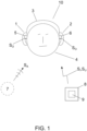
- the headset 10 in FIG. 1 comprises a first earphone 1, a second earphone 2 and a headband 3 mechanically connecting the earphones 1, 2.
- the headset 10 is shown arranged on the head of a user 4 of the headset 10 with each of the earphones 1, 2 arranged in a respective operating position at a respective ear 5, 6 of the user 4.
- the headset 10 receives audio input signals S I from an external device 8, such as e.g.
- the headset base a headset base, a computer, a desktop phone and/or a mobile phone, and the earphones 1, 2 provide corresponding acoustic output signals So to the respective ears 5, 6.
- the external device 8 may comprise a user interface 9 for detecting manipulation by the user 4 and may thus provide corresponding user input signals S U to the headset 10.
- the headset 10 further comprises structures and functional blocks enabling it to operate as an ANC headset that provides the acoustic output signals S O such that ambient sound S A is counteracted in a way that reduces the level of ambient sound S A arriving at the ears 5, 6 while still allowing desired sound, such as music or speech received in the audio input signals S I , to pass through.
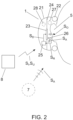
- FIG. 2 shows details of an embodiment of an earphone 1, such as the first earphone 1 and/or the second earphone 2 of the headset 10 of FIG. 1 .
- the earphone 1 comprises a housing 21, an ear cushion 22, an electroacoustic transducer 23 suspended in a baffle 24, a signal processor 25, and a feed-backward microphone 26.
- the earphone 1 is shown arranged in an operating position at an ear 5 of the user 4.
- the housing 21 and the ear cushion 22 are configured to separate a front cavity 27 from ambient space 7 when the earphone 1 is in the operating position.
- the electroacoustic transducer 23 is adapted to radiate an acoustic output signal So into the front cavity 27 and thus provide it to the ear 5.
- the baffle 24 separates the front cavity 27 from a rear cavity 28 to reduce acoustic shorting of the electroacoustic transducer 23.
- the feed-backward microphone 26 is arranged with a sound inlet (not shown) close to a sound-producing element (not shown) of the electroacoustic transducer 23 to enable an accurate pick-up of the acoustic output signal S O radiated by the electroacoustic transducer 23.
- the feed-backward microphone 26 further picks up residual ambient sound S A arriving at its sound inlet and provides a feed-backward reference signal S R in dependence on the sum of the picked-up signals So, S A .
- the signal processor 25 receives an audio input signal S I , e.g.
- the signal processor 25 may further receive a user input signal S U from an external device 8 and provide the audio output signal S D in further dependence on the user input signal Su.
- the earphone 1 further comprises structures and functional blocks (see FIG. 3 ) enabling it to operate as an ANC earphone that provides the acoustic output signal So such that, with the earphone 1 in the operating position, ambient sound S A is counteracted in a way that reduces the level of ambient sound S A arriving at the ear 5 while still allowing desired sound, such as music or speech received in the audio input signal S I , to pass through.
- the feed-backward microphone 26 thereby functions as reference microphone for the feed-backward noise cancellation system of the earphone 1.
- the operating position of the earphone 1 may be any one of the operating positions known from prior art ANC earphones and headsets, such as e.g. an over-the-ear position, an on-the-ear position or an in-the-ear position.
- the earphone 1 - or a headset 10 comprising the earphone 1 - may be configured for such positioning and may comprise any known type of wearing structure, such as a headband, a neckband, an ear hook, an ear wing or the like that assists the user in maintaining the earphone 1 or the headset 10 in an operating position wherein the ANC is effective.
- the ear cushion 22 may be omitted or be replaced by an earbud or other acoustic dampening structure that attenuates ambient sound S A on its way towards the ear 5.
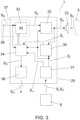
- FIG. 3 shows a functional block schematic of the earphone 1 of FIG. 2 with further details.
- the signal processor 25 comprises an input unit 31, a feed-backward noise cancellation filter 32, an output unit 33, a noise cancellation controller 34, a level analyzer 35 and a transmitter 36.
- the input unit 31 receives the audio input signal S I and the user input signal Su from an external device 8 and provides these to the noise cancellation controller 34.
- the earphone 1 further comprises a feed-backward noise cancellation signal path 37 that comprises the feed-backward microphone 26 and the feed-backward noise cancellation filter 32.
- the feed-backward noise cancellation filter 32 applies a feed-backward transfer function H to the feed-backward reference signal S R from the feed-backward microphone 26 to provide a feed-backward noise cancellation signal Sc.
- the output unit 33 provides the audio output signal S D to the electroacoustic transducer 23 by combining the audio input signal S I and the feed-backward noise cancellation signal Sc.
- the noise cancellation controller 34 adaptively controls the feed-backward transfer function H to cause the acoustic output signal S O to counteract ambient sound S A , such that, with the earphone 1 in the operating position, the level of ambient sound S A arriving at the ear 5 is reduced while still allowing desired sound, such as music or speech received in the audio input signal S I , to pass through.
- a signal path such as the feed-backward noise cancellation signal path 37, that applies a frequency-dependent transfer function to its input signal to provide its output signal
- a wide-band amplifier in series with a frequency-dependent filter.
- decreasing "the wide-band gain" of a signal path shall mean to modify the transfer function of that signal path in a way that, in the above-described model of the signal path, corresponds to decreasing the gain of the wide-band amplifier without modifying the frequency-dependent filter. Note that, for a given signal path, the choice of a starting value for the wide-band gain is arbitrary, since in the model, the transfer function of the frequency-dependent filter may be scaled to complement any choice of wide-band gain value.
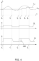
- FIG. 4 illustrates functions of the earphone 1 of FIGs. 2 and 3 and shows an example signal diagram with time t progressing rightwards.
- sound level L logarithmically increases upwards.
- the level analyzer 35 provides, based on an analysis of the audio input signal S I and/or the feed-backward reference signal S R , a sound level estimate L S indicating a total sound level at the ear 5, compares the sound level estimate Ls with a predetermined threshold L T indicating a noise floor level and provides the comparison result S L , as illustrated in the middle section, to the noise cancellation controller 34.
- the noise cancellation controller 34 receives the comparison result S L and uses it to control the wide-band gain G of the feed-backward noise cancellation signal path 37, as illustrated in the lower section with wide-band gain G logarithmically increasing upwards, to cause a decrease ⁇ G of the wide-band gain G in time periods wherein the total sound level at the ear 5 (as indicated by the sound level estimate L S ) is below the noise floor level (as indicated by the predetermined threshold L T ) compared to time periods wherein the total sound level at the ear 5 is above the noise floor level. In the signal diagram, such time periods appear between t 1 and t 2 as well as after t 5 .
- the noise cancellation controller 34 uses the comparison result S L to cause an increase of the wide-band gain G in time periods wherein the total sound level at the ear 5 is above the noise floor level compared to time periods wherein the total sound level at the ear 5 is below the noise floor level.
- time periods appear between t 0 and t 1 as well as between t 2 and t 5 .
- increases of the predetermined threshold L T illustrate adjustments of the noise floor by the user which cause the decrease ⁇ G of the wide-band gain G at time t 5 to appear at a higher total sound level at the ear 5 than without those adjustments.
- the total sound level at the ear 5 shall be understood as the sound level arising from the combination of acoustic output signal So arriving at the ear 5 and (residual) ambient sound S A arriving at the ear 5.
- the level analyzer 35 may thus use the feed-backward reference signal S R as an estimate of the total sound level at the ear 5.
- the level analyzer 35 may further refine such an estimate of the total sound level at the ear 5 using the audio input signal S I , e.g. to separate the contributions of the acoustic output signal S O and the ambient sound S A and thus enable individual compensation for the different acoustic paths leading these sound contributions to the ear 5.
- the level analyzer 35 may further modify such sound contributions using estimated level differences between the location of the reference microphone 26 and the tympanic membrane of the ear 5, e.g. by design or by using estimates of level differences obtained using signals from multiple microphones.
- the effect will, simply put, be that ambient sound S A may arrive at the ear 5 unaffected by the active noise cancellation as long as the combination of the ambient sound S A and the portion of the audio output signal S O that is based on the audio input signal S I has a level at the ear 5 that is below the noise floor level. Conversely, when either of the ambient sound S A and the portion of the audio output signal S O that is based on the audio input signal S I , or the combination thereof, has a level at the ear 5 that is above the noise floor level, then the ambient sound S A will be subject to active noise cancellation.
- the noise cancellation controller 34 may provide a gain control signal S G indicating a decrease ⁇ G of the wide-band gain G of the feed-backward noise cancellation signal path 37, and the transmitter 36 may transmit the gain control signal S G to another device, such as e.g. a respective other one of the first and second earphones 1, 2 of the headset 10. In other embodiments, the transmitter 36 may be omitted.
- the noise cancellation controller 34 may preferably cause the decrease ⁇ G of the wide-band gain G to appear smoothly, e.g. over a time interval of at least 1 s, at least 5 s or at least 10 s, and to cause the increase of the wide-band gain G to appear significantly faster than the decrease ⁇ G of the wide-band gain, e.g. within a time interval of less than 200 ms, less than 100 ms, less than 50 ms or even less than 20 ms.
- a smooth decrease ⁇ G of the wide-band gain G may allow the user to hear low-level ambient sound S A only in pauses in the audio input signal S I , which may comprise e.g. music or speech from a remote party in a telephone or network conversation.
- a fast increase of the wide-band gain G may, on the other hand, enable quick suppression of ambient sound S A when it gets louder.
- the level analyzer 35 preferably performs the comparison such that it at least partly compensates for a frequency dependency and/or level dependency of the ear 5, e.g. by at least partly compensating for the frequency dependency of the average healthy human ear.
- the level analyzer 35 may e.g. perform such compensation by applying the well-known equal-loudness contours when providing the sound level estimate L S .
- the level analyzer 35 may use hearing thresholds obtained for the current user 4 for the compensation.
- the level analyzer 35 may e.g. perform the compensation in the computation of the sound level estimate L S and/or in the comparison itself.
- the decrease ⁇ G of the wide-band gain G in time periods wherein the total sound level at the ear 5 is below the noise floor level may cause the earphone 1 to allow more ambient sound S A to arrive at the ear 5 during such time periods while at the same time reducing the level of noise produced by the ANC system in the audio output signal S O .
- the predetermined threshold L T may preferably be set to indicate a relative low noise floor level, such as within a range of 0 dB to 20 dB above the average healthy human hearing threshold, e.g. within a frequency range from 100 Hz to 1 kHz - or within a wider frequency range.
- the decrease ⁇ G of the wide-band gain G may decrease the noise level perceived by the user 4 in quiet environments.
- the increase of ambient sound S A arriving at the ear 5 may further reduce the acoustic isolation from the environment felt by the user 4.
- the user input signal S U comprises an indication of an action of the user 4, and the level analyzer 35 adjusts the noise floor level indicated by the predetermined threshold L T , based on the indicated action.
- the user input signal S U may e.g. comprise an indication of a first action of the user 4, and the level analyzer 35 may increase the indicated noise floor level in response to the indication of the first action.
- the user input signal S U may comprise an indication of a second action of the user 4, and the level analyzer 35 may decrease the indicated noise floor level in response to the indication of the second action. This allows the user 4 to adjust the level up to which ambient sound S A may arrive at the ear 5 with the earphone in the operating position and may thus allow the user 4 to balance noise cancellation and environment awareness according to personal preference.
- the earphone 1 may comprise a user interface (not shown) that detects manipulation by the user 4 and provides a corresponding user input signal Su to the signal processor 25.
- the earphone 1 and the signal processor 25 may receive a user input signal S U from an external device 8 with a user interface 9 that can be manipulated by the user 4.
- the noise cancellation controller 34 may control the wide-band gain G of the feed-backward noise cancellation signal path 37 by modifying the gain of an amplifier (not shown) comprised by the feed-backward noise cancellation signal path 37 and arranged in series with the feed-backward noise cancellation filter 32.
- the noise cancellation controller 34 may thus set the gain of the amplifier equal to a first gain value when the comparison result S L indicates that the total sound level at the ear 5 is above the noise floor level and set it equal to a second gain value when the comparison result S L indicates that the total sound level at the ear 5 is below the noise floor level, wherein the second gain value equals the first gain value scaled by an amplifier scaling factor below unity.
- the decrease ⁇ G of the wide-band gain G equals the multiplicative inverse of the amplifier scaling factor.
- FIG. 5 shows example transfer functions of the feed-backward transfer function H of the feed-backward noise cancellation filter 32 of an earphone of the earphone 1 of FIG. 2 with filter gain G F logarithmically increasing upwards and signal frequency f increasing rightwards.
- the noise cancellation controller 34 may control the wide-band gain G of the feed-backward noise cancellation signal path 37 by scaling the feed-backward transfer function H.
- the noise cancellation controller 34 may thus set the feed-backward transfer function H equal to a first feed-backward transfer function H 1 when the comparison result S L indicates that the total sound level at the ear 5 is above the noise floor level and set it equal to a second feed-backward transfer function Hz when the comparison result S L indicates that the total sound level at the ear 5 is below the noise floor level, wherein the second feed-backward transfer function H 2 equals the first feed-backward transfer function H 1 scaled by a filter scaling factor below unity.
- the noise cancellation controller 34 applies both a scaling of an amplifier gain and a scaling of the feed-backward transfer function H, then the decrease ⁇ G of the wide-band gain G equals the multiplicative inverse of the product of the amplifier scaling factor and the filter scaling factor, and in this case, one of the amplifier scaling factor and the filter scaling factor may be above unity, provided that their product is below unity. In the case that the noise cancellation controller 34 applies only a scaling of the feed-backward transfer function H, then the decrease ⁇ G of the wide-band gain G equals the multiplicative inverse of the filter scaling factor.
- the level analyzer 35 may provide the comparison result S L such that it indicates the level difference between the total sound level at the ear 5 and the noise floor level, at least when they are close to each other, and the noise cancellation controller 34 may correspondingly apply a partial decrease ⁇ G of the wide-band gain G when the total sound level at the ear 5 is above the noise floor level by a smaller amount, and the full decrease ⁇ G of the wide-band gain G only when the total sound level at the ear 5 is above the noise floor level by a larger amount.
- the noise cancellation controller 34 may further, or alternatively, apply a hysteresis in the activation and deactivation of the decrease ⁇ G of the wide-band gain G.
- the noise cancellation controller 34 may preferably cause the full decrease ⁇ G of the wide-band gain G to amount to about 10 dB or about 6 dB.
- the noise cancellation controller 34 may preferably cause the full decrease ⁇ G of the wide-band gain G to a value of at least 3 dB, at least 6 dB or at least 10 dB.
- the noise cancellation controller 34 may further preferably cause the full decrease ⁇ G of the wide-band gain G to amount to a value of at most 20 dB or at most 12 dB.
- ANC may generally be implemented as feed-backward noise cancellation and/or as feed-forward noise cancellation.
- the noise cancellation signal path 37 is typically part of a closed signal loop that includes an electroacoustic transducer 23 that provides an audio output signal So, a relatively short acoustic path from a sound-producing element of the electroacoustic transducer 23 to a sound inlet of a reference microphone (the feed-backward microphone 26) that picks up the audio output signal S O and ambient sound S A (possibly passively attenuated by structural components of the earphone) and provides a reference signal S R , a noise cancellation filter 32 that filters the reference signal S R to provide a noise cancellation signal Sc and an output unit 33 that combines the noise cancellation signal S C with an audio input signal S I to provide a driving signal S D for the electroacoustic transducer 23.
- the audio output signal So often dominates the reference signal
- the noise cancellation signal path 37 is typically part of an open signal loop that includes the reference microphone 26, however with a sound inlet arranged with a longer and/or acoustically attenuated acoustic path from the sound-producing element of the electroacoustic transducer 23, e.g. at the outside of the housing 21, so that it primarily picks up ambient sound S A to provide the reference signal S R , as well as the noise cancellation filter 32 that filters the reference signal S R to provide a noise cancellation signal Sc and the output unit 33 that combines the noise cancellation signal Sc with the audio input signal S I to provide the driving signal S D for the electroacoustic transducer 23.
- the ambient noise S A often dominates the reference signal S R from the reference microphone 26.
- the feed-backward noise cancellation signal path 37 with the feed-backward microphone 26 and the feed-backward noise cancellation filter 32 may thus be replaced with a feed-forward noise cancellation signal path 37 comprising a feed-forward microphone 26 and a feed-forward noise cancellation filter 32, wherein the feed-forward microphone 26 is arranged to primarily pick up ambient sound S A to provide a feed-forward reference signal S R in dependence on the picked-up signals and wherein the feed-forward noise cancellation filter 32 applies a feed-forward transfer function H to the feed-forward reference signal S R to provide a feed-forward noise cancellation signal S C .
- the output unit 33 may provide the audio output signal S D to the electroacoustic transducer 23 by combining the audio input signal S I and the feed-forward noise cancellation signal Sc, and the signal processor 25 may receive the audio input signal S I and the user input signal Su from an external device 8 as well as the feed-forward reference signal S R , process these signals and provide the resulting audio output signal S D to the electroacoustic transducer 23.
- the noise cancellation controller 34 may adaptively control the feed-forward transfer function H to cause the acoustic output signal S O to counteract ambient sound S A , such that, with the earphone 1 in the operating position, the level of ambient sound S A arriving at the ear 5 is reduced while still allowing desired sound, such as music or speech received in the audio input signal S I , to pass through.
- the feed-forward microphone 26 may thereby function as reference microphone for the for the feed-forward noise cancellation system of the earphone 1.
- the feed-backward noise cancellation signal path 37 with the feed-backward microphone 26 and the feed-backward noise cancellation filter 32 may be complemented by a feed-forward noise cancellation signal path (not shown) comprising a feed-forward microphone and a feed-forward noise cancellation filter, wherein the feed-forward microphone is arranged to primarily pick up ambient sound S A to provide a feed-forward reference signal in dependence on the picked-up signals and wherein the feed-forward noise cancellation filter applies a feed-forward transfer function to the feed-forward reference signal to provide a feed-forward noise cancellation signal.
- the output unit 33 may provide the audio output signal S D to the electroacoustic transducer 23 by combining the audio input signal S I , the feed-backward noise cancellation signal Sc and the feed-forward noise cancellation signal, and the signal processor 25 may receive the audio input signal S I and the user input signal S U from an external device 8 as well as the feed-backward reference signal S R and the feed-forward reference signal, process these signals and provide the resulting audio output signal S D to the electroacoustic transducer 23.
- the noise cancellation controller 34 may adaptively control feed-backward transfer function H and the feed-forward transfer function to cause the acoustic output signal So to counteract ambient sound S A , such that, with the earphone 1 in the operating position, the level of ambient sound S A arriving at the ear 5 is reduced while still allowing desired sound, such as music or speech received in the audio input signal S I , to pass through.
- the feed-backward microphone 26 functions as reference microphone for the feed-backward portion of the noise cancellation system of the earphone 1
- the feed-forward microphone may thus function as reference microphone for the for the feed-forward portion of the noise cancellation system of the earphone 1.
- the noise cancellation controller 34 may be adapted to control the wide-band gain G of the feed-forward noise cancellation signal path 37 in the same way as described above for controlling the wide-band gain G of the feed-backward noise cancellation signal path 37 - in particular to cause a decrease ⁇ G of the wide-band gain G of the feed-forward noise cancellation signal path 37 in time periods wherein the total sound level at the ear 5 is below the noise floor level compared to time periods wherein the total sound level at the ear 5 is above the noise floor level.
- the level analyzer 35 may provide the sound level estimate L S , based on an analysis of at least one of the audio input signal S I and the audio output signal S O and of at least one of the feed-forward reference signal S R and the feed-forward noise cancellation signal Sc in order to estimate the combined impact of the acoustic output signal So and the ambient sound S A .
- the noise cancellation controller 34 may be adapted to control either or both of the wide-band gain G of the feed-backward noise cancellation signal path 37 and the wide-band gain of the feed-forward noise cancellation signal path in the way described above.
- the noise cancellation controller 34 may provide the gain control signal S G to indicate either or both of a decrease ⁇ G of the wide-band gain G of the feed-backward noise cancellation signal path 37 and a decrease of the wide-band gain of the feed-forward noise cancellation signal path.
- the first earphone 1 may comprise an earphone according to any of the embodiments of an earphone 1 described above.
- the second earphone 2 may be omitted.
- each of the first earphone 1 and the second earphone 2 may comprise an earphone according to any of the embodiments of an earphone 1 described above.
- the first earphone 1 may comprise an earphone according to any of the embodiments of an earphone 1 described above, however comprising the transmitter 36 that transmits the gain control signal S G provided by the noise cancellation controller 34.
- the second earphone 2 may comprise an earphone according to any of the embodiments of an earphone 1 described above, however modified to receive the gain control signal S G from the first earphone 1.
- some of the above described functional blocks may, however, be omitted and/or have reduced or changed functionality.
- the second earphone 2 thus comprises at least a housing 21, an electroacoustic transducer 23 suspended in a baffle 24, a signal processor 25, and a reference microphone 26.
- the signal processor 25 of the second earphone 2 comprises at least an input unit 31, a noise cancellation filter 32, an output unit 33 and a noise cancellation controller 34.
- the reception of an audio input signal S I may be omitted.
- the input unit 31 of the second earphone 2 may thus receive the gain control signal S G from the first earphone 1 and optionally, a further audio input signal S I ., e.g. from the first earphone 1 or from an external device 8.
- the reference microphone 26 of the second earphone 2 provides a further reference signal S R in dependence on the picked-up acoustic signals S O , S AR .
- the noise cancellation filter 32 of the second earphone 2 applies a further transfer function H to the further reference signal S R to provide a further noise cancellation signal Sc.
- the output unit 33 of the second earphone 2 may provide a further audio output signal S D in dependence on the further noise cancellation signal S C or by combining the further audio input signal S I and the further noise cancellation signal Sc.
- the electroacoustic transducer 23 of the second earphone 2 provides a further acoustic output signal So in dependence on the further audio output signal S D .
- the noise cancellation controller 34 of the second earphone 2 adaptively controls the further transfer function H to cause the further acoustic output signal So to counteract ambient sound S A , such that, with the second earphone 2 in the operating position, the level of ambient sound S A arriving at the ear 6 is reduced, while optionally still allowing desired sound, such as music or speech received in the audio input signal S I , to pass through, and further controls the wide-band gain G of the noise cancellation signal path 37 of the second earphone 2 in dependence on the gain control signal S G received from the first earphone 1 to cause a decrease ⁇ G of the wide-band gain G of the noise cancellation signal path 37 of the second earphone 2 that is synchronized with the decrease ⁇ G of the wide-band gain G of the noise cancellation signal path 37 of the first earphone 1.
- the level analyzer 35 may thus be omitted.
- the ANC systems of the first earphone 1 and the second earphone 2 are preferably configured with matching types, meaning that preferably both are feed-backward noise cancellation systems, both are feed-forward noise cancellation systems or both are combined feed-backward/feed-forward noise cancellation systems.
- any of the described devices may comprise further structures, functional blocks and/or circuits as readily known in the art, e.g. for further noise filtering, for picking up speech audio from the user 4 and transmitting corresponding audio signals to an external device 8 and/or an external network, for cancelling echoes in such transmitted audio signals and/or for receiving and processing further user input.
- Signals such as the audio input signal S I , the user input signal Su, the gain control signal S G as well as any transmitted audio signals may be transmitted, conveyed and/or received by wired or wireless connections, and any of the described devices may comprise wired or wireless receivers, transmitters and/or transceivers for this and other purposes.
- the described devices may be implemented using analog or digital circuits, or mixtures hereof.
- Functional blocks of digital circuits may be implemented in hardware, firmware or software, or any combination hereof.
- Digital circuits may perform the functions of multiple functional blocks in parallel and/or in interleaved sequence, and functional blocks may be distributed in any suitable way among multiple hardware units, such as e.g. dedicated signal processors, microcontrollers and other integrated circuits.
Landscapes
- Physics & Mathematics (AREA)
- Engineering & Computer Science (AREA)
- Acoustics & Sound (AREA)
- Signal Processing (AREA)
- Multimedia (AREA)
- Soundproofing, Sound Blocking, And Sound Damping (AREA)
- Circuit For Audible Band Transducer (AREA)
- Headphones And Earphones (AREA)
Claims (14)
- Ohrhörer (1), der dazu ausgelegt ist, in einer Betriebsposition an einem ersten Ohr (5) eines Benutzers (4) angeordnet zu werden und in der Betriebsposition ein erstes akustisches Ausgangssignal (SO) an das erste Ohr (5) abzugeben, wobei der Ohrhörer folgendes umfasst:- eine erste Eingabeeinheit (31), die zum Empfangen eines ersten Audioeingangssignals (SI) ausgelegt ist;- einen ersten Geräuschunterdrückungssignalpfad (37) mit einem ersten Mikrofon (26) und einem ersten Geräuschunterdrückungsfilter (32), wobei das erste Mikrofon (26) dafür angeordnet ist, Umgebungsgeräusch (SA) aus dem Umgebungsraum (7) zu empfangen, während sich der Ohrhörer in der Betriebsposition befindet, und dazu ausgelegt ist, ein entsprechendes erstes Referenzsignal (SR) bereitzustellen, und wobei der erste Geräuschunterdrückungsfilter (32) dazu ausgelegt ist, eine erste Übertragungsfunktion (H) auf das erste Referenzsignal (SR) anzuwenden, um ein erstes Geräuschunterdrückungssignal (Sc) bereitzustellen;- eine erste Ausgabeeinheit (33), die dazu ausgelegt ist, ein erstes Audioausgangssignal (SD) durch Kombinieren des ersten Audioeingangssignals (SI) und des ersten Geräuschunterdrückungssignals (SC) bereitzustellen;- einen ersten elektroakustischen Wandler (23), der dazu ausgelegt ist, das erste akustische Ausgangssignal (SO) in Abhängigkeit von dem ersten Audioausgangssignal (SD) bereitzustellen; und- einen ersten Geräuschunterdrückungsregler (34), der dazu ausgelegt ist, die erste Übertragungsfunktion (H) des ersten Geräuschunterdrückungsfilters (32) adaptiv zu steuern, um das erste akustische Ausgangssignal (SO) dazu zu bewirken Umgebungsgeräusch (SA) entgegenzuwirken, so dass, während sich der Ohrhörer in der Betriebsposition befindet, der Pegel des am ersten Ohr (5) ankommenden Umgebungsgeräusches (SA), verringert wird, und dabei weiterhin den gewünschten Schall von dem ersten Audioeingangssignal (SI) durchzulassen,wobei:- der Ohrhörer ferner einen Pegelanalysator (35) aufweist, der dazu ausgelegt ist, auf der Grundlage einer Analyse des ersten Audioeingangssignals (SI) und/oder des ersten Referenzsignals (SR) eine Schallpegelschätzung (LS) bereitzustellen, die einen Gesamtschallpegel am ersten Ohr (5) anzeigt, und die Schallpegelschätzung (LS) mit einem vorgegebenen Schwellenwert (LT), der einen Grundgeräuschpegel angibt, zu vergleichen; und- der erste Geräuschunterdrückungsregler (34) ferner dazu ausgelegt ist, in Abhängigkeit von dem Vergleich die Breitbandverstärkung (G) des ersten Geräuschunterdrückungssignalpfads (37) zu steuern, um eine Verringerung (ΔG) der Breitbandverstärkung (G) in Zeiträumen zu bewirken, in denen der Gesamtschallpegel am ersten Ohr (5) unter dem Grundgeräuschpegel liegt, verglichen mit Zeiträumen, in denen der Gesamtschallpegel am ersten Ohr (5) über dem Grundgeräuschpegel liegt,wobei ferner der erste Geräuschunterdrückungssignalpfad (37) einer von folgenden ist:- ein Rückkopplungs-Geräuschunterdrückungssignalpfad, worin das erste Mikrofon (26) ein Rückkopplungs-Mikrofon ist, das angeordnet ist, um das erste akustische Ausgangssignal (So), das von dem elektroakustischen Wandler (23) bereitgestellt wird, und restlichen Umgebungsgeräusch (SA) aufzunehmen, und worin der erste Geräuschunterdrückungsfilter (32) ein Rückkopplungs-Geräuschunterdrückungsfilter ist; und- ein Vorwärts-Geräuschunterdrückungssignalweg, worin das erste Mikrofon (26) ein Vorwärts-Mikrofon ist, das hauptsächlich zur Aufnahme von Umgebungsgeräusch (SA) angeordnet ist, und worin der erste Geräuschunterdrückungsfilter (32) ein Vorwärts-Geräuschunterdrückungsfilter ist, wobei der Ohrhörer ferner dadurch gekennzeichnet ist, dass der Pegelanalysator (35) ferner dazu ausgelegt ist, den angezeigten Grundgeräuschpegel anzupassen, während sich der Ohrhörer in der Betriebsposition befindet, basierend auf einem Benutzereingabesignal (SU), das eine Aktion des Benutzers (4) anzeigt, wie z.B. auf einem über eine vom Ohrhörer umfasste Benutzerschnittstelle empfangenen Benutzereingabesignal (SU), oder auf einem über eine von einer externen Vorrichtung (8) umfasste Benutzerschnittstelle (9) empfangenen Benutzereingabesignal (SU).
- Ohrhörer nach Anspruch 1, wobei der Pegelanalysator (35) ferner dazu ausgelegt ist, den Vergleich derart durchzuführen, dass er eine Frequenzabhängigkeit und/oder Pegelabhängigkeit des ersten Ohrs (5) zumindest teilweise kompensiert, z. B. durch eine zumindest teilweise Kompensierung der Frequenzabhängigkeit des durchschnittlichen gesunden menschlichen Ohrs.
- Ohrhörer nach Anspruch 2, wobei der vorgegebene Schwellenwert (LT) einen Grundgeräuschpegel innerhalb eines Bereichs von 0 dB bis 20 dB über der durchschnittlichen gesunden menschlichen Hörschwelle anzeigt, zumindest innerhalb eines Frequenzbereichs von 100 Hz bis 1 kHz.
- Ohrhörer nach einem der vorhergehenden Ansprüche, wobei der vorgegebene Schwellenwert (LT) derart bestimmt ist, dass die Verringerung (ΔG) der Breitbandverstärkung (G) eine Verringerung des vom Benutzer (4) wahrgenommenen Geräuschpegels bewirkt.
- Ohrhörer nach einem der vorhergehenden Ansprüche, wobei die Verringerung (ΔG) der Breitbandverstärkung (G) mindestens 3 dB, mindestens 6 dB oder mindestens 10 dB beträgt.
- Ohrhörer nach einem der vorhergehenden Ansprüche, wobei die Verringerung (ΔG) der Breitbandverstärkung (G) höchstens 20 dB oder höchstens 12 dB beträgt.
- Ohrhörer nach einem der vorhergehenden Ansprüche, und ferner umfassend:- einen zweiten Geräuschunterdrückungssignalpfad (37) mit einem zweiten Mikrofon (26) und einem zweiten Geräuschunterdrückungsfilter (32), wobei das zweite Mikrofon (26) dafür angeordnet ist, Umgebungsgeräusch (SA) aus dem Umgebungsraum (7) zu empfangen, während sich der Ohrhörer in der Betriebsposition befindet, und dazu ausgelegt ist, ein entsprechendes zweites Referenzsignal (SR) bereitzustellen, und wobei der zweite Geräuschunterdrückungsfilter (32) dazu ausgelegt ist, eine zweite Übertragungsfunktion (H) auf das zweite Referenzsignal (SR) anzuwenden, um ein zweites Geräuschunterdrückungssignal (Sc) bereitzustellen,und wobei- die Ausgabeeinheit (33) ferner dazu ausgelegt ist, das erste Audioausgangssignal (SD) durch Kombinieren des ersten Audioeingangssignals (SI), des ersten Geräuschunterdrückungssignals (Sc) und des zweiten Geräuschunterdrückungssignals (Sc) bereitzustellen; und- der Geräuschunterdrückungsregler (34) ferner dazu ausgelegt ist, die zweite Übertragungsfunktion (H) des zweiten Geräuschunterdrückungsfilters (32) adaptiv zu steuern, um das erste akustische Ausgangssignal (So) dazu zu bewirken Umgebungsgeräusch (SA) entgegenzuwirken, so dass, während sich der Ohrhörer in der Betriebsposition befindet, der Pegel des am ersten Ohr (5) ankommenden Umgebungsgeräusches (SA) verringert wird, und dabei weiterhin den gewünschten Schall von dem ersten Audioeingangssignal (SI) durchzulassen, wobei ferner der zweite Geräuschunterdrückungssignalpfad (37) einer der folgenden ist:- ein Rückkopplungs-Geräuschunterdrückungssignalpfad, worin das zweite Mikrofon (26) ein Rückkopplungs-Mikrofon ist, das dafür angeordnet ist, das erste akustische Ausgangssignal (So), das von dem elektroakustischen Wandler (23) bereitgestellt wird, und restlichen Umgebungsgeräusch (SA) aufzunehmen, und worin der zweite Geräuschunterdrückungsfilter (32) ein Rückkopplungs-Geräuschunterdrückungsfilter ist, und- ein Vorwärts-Geräuschunterdrückungssignalpfad, worin das zweite Mikrofon (26) ein Vorwärts-Mikrofon ist, das hauptsächlich zur Aufnahme von Umgebungsgeräusch (SA) angeordnet ist, und wobei der zweite Geräuschunterdrückungsfilter (32) ein Vorwärts-Geräuschunterdrückungsfilter ist,wobei ferner:- einer der ersten und zweiten Geräuschunterdrückungssignalpfade (37) ein Vorwärts-Geräuschunterdrückungssignalpfad ist, und- der jeweils andere der ersten und zweiten Geräuschunterdrückungssignalpfade (37) ein Rückkopplungs-Geräuschunterdrückungssignalpfad ist.
- Ohrhörer nach einem der vorhergehenden Ansprüche, wobei der erste Geräuschunterdrückungssignalpfad (37) ein Vorwärts-Geräuschunterdrückungssignalpfad ist.
- Ohrhörer nach einem der vorhergehenden Ansprüche 1 bis 7, wobei der erste Geräuschunterdrückungssignalpfad (37) ein Rückkopplungs-Geräuschunterdrückungssignalpfad ist.
- Ohrhörer nach Anspruch 9, wobei der Pegelanalysator (35) ferner dazu ausgelegt ist, die Schallpegelschätzung (LS) auf der Grundlage einer Analyse des ersten Audioausgangssignals (SD) bereitzustellen.
- Ohrhörer nach einem der vorhergehenden Ansprüche, wobei der Pegelanalysator (35) ferner dazu ausgelegt ist, die Schallpegelschätzung (LS) auf der Grundlage einer Analyse von mindestens einem des ersten Audioeingangssignals (SI) und des ersten Audioausgangssignals (SD) und von mindestens einem des ersten Referenzsignals (SR) und des ersten Geräuschunterdrückungssignals (SC) bereitzustellen.
- Ohrhörer nach einem der vorhergehenden Ansprüche,- wobei der erste Geräuschunterdrückungsregler (34) ferner dazu ausgelegt ist, ein Verstärkungssteuerungssignal (SG) bereitzustellen, das eine Verringerung (ΔG) der Breitbandverstärkung (G) des ersten Geräuschunterdrückungssignalpfads (37) anzeigt, und- wobei der Ohrhörer ferner einen Sender (36) umfasst, der dazu ausgelegt ist, das Verstärkungssteuerungssignal (SG) an eine andere Vorrichtung zu übertragen.
- Kopfhörer mit einem oder zwei Ohrhörern (1) nach einem der vorhergehenden Ansprüche.
- Kopfhörer mit einem ersten Ohrhörer (1) nach Anspruch 12 und mit einem zweiten Ohrhörer (2), der folgendes umfasst:- eine zweite Eingabeeinheit (31), die zum Empfangen des Verstärkungssteuerungssignal (SG) von dem ersten Ohrhörer (1) ausgelegt ist;- einen dritten Geräuschunterdrückungssignalpfad (37) mit einem dritten Mikrofon (26) und einem dritten Geräuschunterdrückungsfilter (32), wobei das dritte Mikrofon (26) dafür angeordnet ist, Umgebungsgeräusch (SA) aus dem Umgebungsraum (7) zu empfangen, während sich der zweite Ohrhörer (2) in einer Betriebsposition an einem zweiten Ohr (6) des Benutzers (4) befindet, und dazu ausgelegt ist, ein entsprechendes drittes Referenzsignal (SR) bereitzustellen, und wobei der dritte Geräuschunterdrückungsfilter (32) dazu ausgelegt ist, eine dritte Übertragungsfunktion (H) auf das dritte Referenzsignal (SR) anzuwenden, um ein drittes Geräuschunterdrückungssignal (Sc) bereitzustellen;- eine zweite Ausgabeeinheit (33), die dazu ausgelegt ist, ein zweites Audioausgangssignal (SD) in Abhängigkeit von dem dritten Geräuschunterdrückungssignal (Sc) bereitzustellen;- ein zweiter elektroakustischer Wandler (23), der dazu ausgelegt ist, ein zweites akustisches Ausgangssignal (SO) in Abhängigkeit von dem zweiten Audioausgangssignal (SD) bereitzustellen; und- einen zweiten Geräuschunterdrückungsregler (34), der dazu ausgelegt ist, die dritte Übertragungsfunktion (H) des dritten Geräuschunterdrückungsfilters (32) adaptiv zu steuern, um das zweite akustische Ausgangssignal (SO) dazu zu bewirken Umgebungsgeräusch (SA) entgegenzuwirken, so dass, während sich der zweite Ohrhörer (2) in der Betriebsposition befindet, der Pegel des am zweiten Ohr (6) ankommenden Umgebungsgeräusches (SA), verringert wird, und ferner dazu ausgelegt ist, die Breitbandverstärkung des dritten Geräuschunterdrückungssignalpfads (37) in Abhängigkeit von dem Verstärkungssteuerungssignal (SG) zu steuern, um eine Verringerung der Breitbandverstärkung des dritten Geräuschunterdrückungssignalpfads (37) zu bewirken, der mit der Verringerung (ΔG) der Breitbandverstärkung (G) des ersten Geräuschunterdrückungssignalpfads (37) des ersten Ohrhörers (1) synchronisiert ist.
Applications Claiming Priority (1)
| Application Number | Priority Date | Filing Date | Title |
|---|---|---|---|
| DKPA201900412A DK180471B1 (en) | 2019-04-03 | 2019-04-03 | Headset with active noise cancellation |
Publications (3)
| Publication Number | Publication Date |
|---|---|
| EP3720144A1 EP3720144A1 (de) | 2020-10-07 |
| EP3720144C0 EP3720144C0 (de) | 2024-09-04 |
| EP3720144B1 true EP3720144B1 (de) | 2024-09-04 |
Family
ID=70165866
Family Applications (1)
| Application Number | Title | Priority Date | Filing Date |
|---|---|---|---|
| EP20167783.8A Active EP3720144B1 (de) | 2019-04-03 | 2020-04-02 | Kopfhörer mit aktiver geräuschunterdrückung |
Country Status (4)
| Country | Link |
|---|---|
| US (1) | US10957301B2 (de) |
| EP (1) | EP3720144B1 (de) |
| CN (1) | CN111800690B (de) |
| DK (1) | DK180471B1 (de) |
Families Citing this family (21)
| Publication number | Priority date | Publication date | Assignee | Title |
|---|---|---|---|---|
| US11615775B2 (en) | 2020-06-16 | 2023-03-28 | Qualcomm Incorporated | Synchronized mode transition |
| EP4218004B1 (de) * | 2020-10-20 | 2024-03-20 | Huawei Technologies Co., Ltd. | Vorrichtung und verfahren zur binauralen sprachverbesserung |
| CN112637724B (zh) * | 2020-12-29 | 2023-08-08 | 西安讯飞超脑信息科技有限公司 | 耳机降噪方法、系统及存储介质 |
| CN116803100A (zh) * | 2021-01-14 | 2023-09-22 | 哈曼国际工业有限公司 | 用于具有anc的耳机的方法和系统 |
| CN112929807B (zh) * | 2021-01-25 | 2022-09-13 | 深圳市卓翼科技股份有限公司 | 自动校正滤波器系数的方法、系统、测试终端及存储介质 |
| CN113099340B (zh) * | 2021-03-23 | 2023-06-23 | 中山大学附属口腔医院 | 一种基于牙科诊室噪声的降噪方法及装置 |
| CN113115157B (zh) * | 2021-04-13 | 2024-05-03 | 北京安声科技有限公司 | 耳机的主动降噪方法及装置、半入耳式主动降噪耳机 |
| CN113068098A (zh) * | 2021-05-08 | 2021-07-02 | 深圳荣腾声学科技有限公司 | 一种耳机主动降噪方法及主动降噪耳机 |
| US11501749B1 (en) * | 2021-08-09 | 2022-11-15 | International Business Machines Corporation | Selective allowance of sound in noise cancellation headset in an industrial work environment |
| CN113645532B (zh) * | 2021-08-17 | 2023-10-20 | 恒玄科技(上海)股份有限公司 | 一种具备anc的耳机的自适应处理方法及具备anc的耳机 |
| US12323769B1 (en) | 2021-10-25 | 2025-06-03 | Chromatic Inc. | Ear-worn device configured for over-the-counter and prescription use |
| CN114125625B (zh) * | 2021-10-28 | 2022-07-22 | 歌尔科技有限公司 | 降噪调整方法、耳机及计算机可读存储介质 |
| CN114071309B (zh) * | 2021-12-20 | 2023-08-25 | 歌尔科技有限公司 | 耳机降噪方法、装置、设备及计算机可读存储介质 |
| US11818547B2 (en) * | 2022-01-14 | 2023-11-14 | Chromatic Inc. | Method, apparatus and system for neural network hearing aid |
| US11832061B2 (en) * | 2022-01-14 | 2023-11-28 | Chromatic Inc. | Method, apparatus and system for neural network hearing aid |
| US11950056B2 (en) | 2022-01-14 | 2024-04-02 | Chromatic Inc. | Method, apparatus and system for neural network hearing aid |
| US12418756B2 (en) | 2022-01-14 | 2025-09-16 | Chromatic Inc. | System and method for enhancing speech of target speaker from audio signal in an ear-worn device using voice signatures |
| US12075215B2 (en) | 2022-01-14 | 2024-08-27 | Chromatic Inc. | Method, apparatus and system for neural network hearing aid |
| US12231851B1 (en) | 2022-01-24 | 2025-02-18 | Chromatic Inc. | Method, apparatus and system for low latency audio enhancement |
| EP4333464A1 (de) | 2022-08-09 | 2024-03-06 | Chromatic Inc. | Hörverlustverstärkung, die sprach- und geräuschuntersignale unterschiedlich verstärkt |
| US20250106544A1 (en) * | 2023-09-21 | 2025-03-27 | Bose Corporation | Adaptive Interface in Active Noise Reduction (ANR) Headset |
Citations (1)
| Publication number | Priority date | Publication date | Assignee | Title |
|---|---|---|---|---|
| US20150104031A1 (en) * | 2013-10-14 | 2015-04-16 | Qualcomm Incorporated | Limiting active noise cancellation output |
Family Cites Families (16)
| Publication number | Priority date | Publication date | Assignee | Title |
|---|---|---|---|---|
| GB2436657B (en) | 2006-04-01 | 2011-10-26 | Sonaptic Ltd | Ambient noise-reduction control system |
| GB0725110D0 (en) | 2007-12-21 | 2008-01-30 | Wolfson Microelectronics Plc | Gain control based on noise level |
| JP4572945B2 (ja) * | 2008-03-28 | 2010-11-04 | ソニー株式会社 | ヘッドフォン装置、信号処理装置、信号処理方法 |
| US8208650B2 (en) | 2009-04-28 | 2012-06-26 | Bose Corporation | Feedback-based ANR adjustment responsive to environmental noise levels |
| CN103366728B (zh) | 2009-04-28 | 2016-08-10 | 伯斯有限公司 | 具有自适应增益的anr |
| US8280066B2 (en) | 2009-04-28 | 2012-10-02 | Bose Corporation | Binaural feedforward-based ANR |
| US20140126733A1 (en) | 2012-11-02 | 2014-05-08 | Daniel M. Gauger, Jr. | User Interface for ANR Headphones with Active Hear-Through |
| US9607602B2 (en) * | 2013-09-06 | 2017-03-28 | Apple Inc. | ANC system with SPL-controlled output |
| US9620101B1 (en) * | 2013-10-08 | 2017-04-11 | Cirrus Logic, Inc. | Systems and methods for maintaining playback fidelity in an audio system with adaptive noise cancellation |
| FR3019961A1 (fr) | 2014-04-11 | 2015-10-16 | Parrot | Casque audio a controle actif de bruit anc avec reduction du souffle electrique |
| US20170110105A1 (en) | 2015-10-16 | 2017-04-20 | Avnera Corporation | Active noise cancelation with controllable levels |
| USD835076S1 (en) * | 2016-11-01 | 2018-12-04 | Safariland, Llc | Speaker and microphone housing |
| US20180176672A1 (en) | 2016-12-18 | 2018-06-21 | Matthew Robert Adkins | Automatic Noise Cancelling Earbuds |
| CN109429147B (zh) * | 2017-08-30 | 2021-01-05 | 美商富迪科技股份有限公司 | 电子装置与电子装置的控制方法 |
| US11087776B2 (en) | 2017-10-30 | 2021-08-10 | Bose Corporation | Compressive hear-through in personal acoustic devices |
| US10586523B1 (en) * | 2019-03-29 | 2020-03-10 | Sonova Ag | Hearing device with active noise control based on wind noise |
-
2019
- 2019-04-03 DK DKPA201900412A patent/DK180471B1/en active IP Right Grant
-
2020
- 2020-03-17 US US16/821,864 patent/US10957301B2/en active Active
- 2020-03-30 CN CN202010239463.9A patent/CN111800690B/zh active Active
- 2020-04-02 EP EP20167783.8A patent/EP3720144B1/de active Active
Patent Citations (1)
| Publication number | Priority date | Publication date | Assignee | Title |
|---|---|---|---|---|
| US20150104031A1 (en) * | 2013-10-14 | 2015-04-16 | Qualcomm Incorporated | Limiting active noise cancellation output |
Also Published As
| Publication number | Publication date |
|---|---|
| DK201900412A1 (en) | 2020-11-17 |
| EP3720144C0 (de) | 2024-09-04 |
| CN111800690B (zh) | 2022-11-18 |
| US10957301B2 (en) | 2021-03-23 |
| US20200320972A1 (en) | 2020-10-08 |
| DK180471B1 (en) | 2021-05-06 |
| CN111800690A (zh) | 2020-10-20 |
| EP3720144A1 (de) | 2020-10-07 |
Similar Documents
| Publication | Publication Date | Title |
|---|---|---|
| EP3720144B1 (de) | Kopfhörer mit aktiver geräuschunterdrückung | |
| US11978469B1 (en) | Ambient noise aware dynamic range control and variable latency for hearing personalization | |
| US10748549B2 (en) | Audio signal processing for noise reduction | |
| CN111902866B (zh) | 头戴式耳机中的双耳自适应噪声消除系统中的回声控制 | |
| JP6965216B2 (ja) | Anrヘッドホンで周囲の自然さを提供すること | |
| EP3189672B1 (de) | Regelung der raumklanglautstärke | |
| US11887576B2 (en) | Ambient detector for dual mode ANC | |
| EP2915341B1 (de) | Binaurale telepräsenz | |
| US9190043B2 (en) | Assisting conversation in noisy environments | |
| EP2915337B1 (de) | Benutzerschnittstelle für anr-kopfhörer mit aktivem durchhören | |
| CN114466277A (zh) | 具有听通模式的头戴式耳机及其操作方法 | |
| EP2915340A1 (de) | Bereitstellung von simultanem audio- und umgebungston bei anr-kopfhörern | |
| EP2915338A1 (de) | Reduzierung des okklusionseffekts bei anr-kopfhörern | |
| EP3213527A1 (de) | Minderung der okklusion der eigenen stimme bei kopfhörern | |
| EP3840402B1 (de) | Elektronische wearable vorrichtung mit tief-frequenz-rauschverminderung | |
| US20230328462A1 (en) | Method, device, headphones and computer program for actively suppressing the occlusion effect during the playback of audio signals | |
| US20240005903A1 (en) | Headphone Speech Listening Based on Ambient Noise |
Legal Events
| Date | Code | Title | Description |
|---|---|---|---|
| PUAI | Public reference made under article 153(3) epc to a published international application that has entered the european phase |
Free format text: ORIGINAL CODE: 0009012 |
|
| STAA | Information on the status of an ep patent application or granted ep patent |
Free format text: STATUS: THE APPLICATION HAS BEEN PUBLISHED |
|
| AK | Designated contracting states |
Kind code of ref document: A1 Designated state(s): AL AT BE BG CH CY CZ DE DK EE ES FI FR GB GR HR HU IE IS IT LI LT LU LV MC MK MT NL NO PL PT RO RS SE SI SK SM TR |
|
| AX | Request for extension of the european patent |
Extension state: BA ME |
|
| STAA | Information on the status of an ep patent application or granted ep patent |
Free format text: STATUS: REQUEST FOR EXAMINATION WAS MADE |
|
| 17P | Request for examination filed |
Effective date: 20210326 |
|
| RBV | Designated contracting states (corrected) |
Designated state(s): AL AT BE BG CH CY CZ DE DK EE ES FI FR GB GR HR HU IE IS IT LI LT LU LV MC MK MT NL NO PL PT RO RS SE SI SK SM TR |
|
| STAA | Information on the status of an ep patent application or granted ep patent |
Free format text: STATUS: EXAMINATION IS IN PROGRESS |
|
| 17Q | First examination report despatched |
Effective date: 20220318 |
|
| REG | Reference to a national code |
Ref country code: DE Ref legal event code: R079 Free format text: PREVIOUS MAIN CLASS: H04R0003000000 Ipc: H04R0001100000 Ref country code: DE Ref legal event code: R079 Ref document number: 602020036915 Country of ref document: DE Free format text: PREVIOUS MAIN CLASS: H04R0003000000 Ipc: H04R0001100000 |
|
| GRAP | Despatch of communication of intention to grant a patent |
Free format text: ORIGINAL CODE: EPIDOSNIGR1 |
|
| STAA | Information on the status of an ep patent application or granted ep patent |
Free format text: STATUS: GRANT OF PATENT IS INTENDED |
|
| INTG | Intention to grant announced |
Effective date: 20231110 |
|
| RIC1 | Information provided on ipc code assigned before grant |
Ipc: H04R 1/10 20060101AFI20231027BHEP |
|
| GRAJ | Information related to disapproval of communication of intention to grant by the applicant or resumption of examination proceedings by the epo deleted |
Free format text: ORIGINAL CODE: EPIDOSDIGR1 |
|
| STAA | Information on the status of an ep patent application or granted ep patent |
Free format text: STATUS: EXAMINATION IS IN PROGRESS |
|
| GRAP | Despatch of communication of intention to grant a patent |
Free format text: ORIGINAL CODE: EPIDOSNIGR1 |
|
| STAA | Information on the status of an ep patent application or granted ep patent |
Free format text: STATUS: GRANT OF PATENT IS INTENDED |
|
| INTG | Intention to grant announced |
Effective date: 20240322 |
|
| GRAS | Grant fee paid |
Free format text: ORIGINAL CODE: EPIDOSNIGR3 |
|
| GRAA | (expected) grant |
Free format text: ORIGINAL CODE: 0009210 |
|
| STAA | Information on the status of an ep patent application or granted ep patent |
Free format text: STATUS: THE PATENT HAS BEEN GRANTED |
|
| AK | Designated contracting states |
Kind code of ref document: B1 Designated state(s): AL AT BE BG CH CY CZ DE DK EE ES FI FR GB GR HR HU IE IS IT LI LT LU LV MC MK MT NL NO PL PT RO RS SE SI SK SM TR |
|
| REG | Reference to a national code |
Ref country code: GB Ref legal event code: FG4D |
|
| REG | Reference to a national code |
Ref country code: CH Ref legal event code: EP |
|
| REG | Reference to a national code |
Ref country code: IE Ref legal event code: FG4D |
|
| REG | Reference to a national code |
Ref country code: DE Ref legal event code: R096 Ref document number: 602020036915 Country of ref document: DE |
|
| U01 | Request for unitary effect filed |
Effective date: 20240905 |
|
| U07 | Unitary effect registered |
Designated state(s): AT BE BG DE DK EE FI FR IT LT LU LV MT NL PT RO SE SI Effective date: 20240923 |
|
| PG25 | Lapsed in a contracting state [announced via postgrant information from national office to epo] |
Ref country code: NO Free format text: LAPSE BECAUSE OF FAILURE TO SUBMIT A TRANSLATION OF THE DESCRIPTION OR TO PAY THE FEE WITHIN THE PRESCRIBED TIME-LIMIT Effective date: 20241204 |
|
| PG25 | Lapsed in a contracting state [announced via postgrant information from national office to epo] |
Ref country code: PL Free format text: LAPSE BECAUSE OF FAILURE TO SUBMIT A TRANSLATION OF THE DESCRIPTION OR TO PAY THE FEE WITHIN THE PRESCRIBED TIME-LIMIT Effective date: 20240904 Ref country code: GR Free format text: LAPSE BECAUSE OF FAILURE TO SUBMIT A TRANSLATION OF THE DESCRIPTION OR TO PAY THE FEE WITHIN THE PRESCRIBED TIME-LIMIT Effective date: 20241205 |
|
| PG25 | Lapsed in a contracting state [announced via postgrant information from national office to epo] |
Ref country code: HR Free format text: LAPSE BECAUSE OF FAILURE TO SUBMIT A TRANSLATION OF THE DESCRIPTION OR TO PAY THE FEE WITHIN THE PRESCRIBED TIME-LIMIT Effective date: 20240904 |
|
| PG25 | Lapsed in a contracting state [announced via postgrant information from national office to epo] |
Ref country code: RS Free format text: LAPSE BECAUSE OF FAILURE TO SUBMIT A TRANSLATION OF THE DESCRIPTION OR TO PAY THE FEE WITHIN THE PRESCRIBED TIME-LIMIT Effective date: 20241204 Ref country code: ES Free format text: LAPSE BECAUSE OF FAILURE TO SUBMIT A TRANSLATION OF THE DESCRIPTION OR TO PAY THE FEE WITHIN THE PRESCRIBED TIME-LIMIT Effective date: 20240904 |
|
| PG25 | Lapsed in a contracting state [announced via postgrant information from national office to epo] |
Ref country code: RS Free format text: LAPSE BECAUSE OF FAILURE TO SUBMIT A TRANSLATION OF THE DESCRIPTION OR TO PAY THE FEE WITHIN THE PRESCRIBED TIME-LIMIT Effective date: 20241204 Ref country code: PL Free format text: LAPSE BECAUSE OF FAILURE TO SUBMIT A TRANSLATION OF THE DESCRIPTION OR TO PAY THE FEE WITHIN THE PRESCRIBED TIME-LIMIT Effective date: 20240904 Ref country code: NO Free format text: LAPSE BECAUSE OF FAILURE TO SUBMIT A TRANSLATION OF THE DESCRIPTION OR TO PAY THE FEE WITHIN THE PRESCRIBED TIME-LIMIT Effective date: 20241204 Ref country code: HR Free format text: LAPSE BECAUSE OF FAILURE TO SUBMIT A TRANSLATION OF THE DESCRIPTION OR TO PAY THE FEE WITHIN THE PRESCRIBED TIME-LIMIT Effective date: 20240904 Ref country code: GR Free format text: LAPSE BECAUSE OF FAILURE TO SUBMIT A TRANSLATION OF THE DESCRIPTION OR TO PAY THE FEE WITHIN THE PRESCRIBED TIME-LIMIT Effective date: 20241205 Ref country code: ES Free format text: LAPSE BECAUSE OF FAILURE TO SUBMIT A TRANSLATION OF THE DESCRIPTION OR TO PAY THE FEE WITHIN THE PRESCRIBED TIME-LIMIT Effective date: 20240904 |
|
| PG25 | Lapsed in a contracting state [announced via postgrant information from national office to epo] |
Ref country code: IS Free format text: LAPSE BECAUSE OF FAILURE TO SUBMIT A TRANSLATION OF THE DESCRIPTION OR TO PAY THE FEE WITHIN THE PRESCRIBED TIME-LIMIT Effective date: 20250104 |
|
| PG25 | Lapsed in a contracting state [announced via postgrant information from national office to epo] |
Ref country code: SM Free format text: LAPSE BECAUSE OF FAILURE TO SUBMIT A TRANSLATION OF THE DESCRIPTION OR TO PAY THE FEE WITHIN THE PRESCRIBED TIME-LIMIT Effective date: 20240904 |
|
| PG25 | Lapsed in a contracting state [announced via postgrant information from national office to epo] |
Ref country code: CZ Free format text: LAPSE BECAUSE OF FAILURE TO SUBMIT A TRANSLATION OF THE DESCRIPTION OR TO PAY THE FEE WITHIN THE PRESCRIBED TIME-LIMIT Effective date: 20240904 |
|
| PG25 | Lapsed in a contracting state [announced via postgrant information from national office to epo] |
Ref country code: SK Free format text: LAPSE BECAUSE OF FAILURE TO SUBMIT A TRANSLATION OF THE DESCRIPTION OR TO PAY THE FEE WITHIN THE PRESCRIBED TIME-LIMIT Effective date: 20240904 |
|
| U20 | Renewal fee for the european patent with unitary effect paid |
Year of fee payment: 6 Effective date: 20250415 |
|
| PGFP | Annual fee paid to national office [announced via postgrant information from national office to epo] |
Ref country code: GB Payment date: 20250422 Year of fee payment: 6 |
|
| PLBE | No opposition filed within time limit |
Free format text: ORIGINAL CODE: 0009261 |
|
| STAA | Information on the status of an ep patent application or granted ep patent |
Free format text: STATUS: NO OPPOSITION FILED WITHIN TIME LIMIT |
|
| 26N | No opposition filed |
Effective date: 20250605 |
|
| REG | Reference to a national code |
Ref country code: CH Ref legal event code: H13 Free format text: ST27 STATUS EVENT CODE: U-0-0-H10-H13 (AS PROVIDED BY THE NATIONAL OFFICE) Effective date: 20251125 |
|
| PG25 | Lapsed in a contracting state [announced via postgrant information from national office to epo] |
Ref country code: MC Free format text: LAPSE BECAUSE OF FAILURE TO SUBMIT A TRANSLATION OF THE DESCRIPTION OR TO PAY THE FEE WITHIN THE PRESCRIBED TIME-LIMIT Effective date: 20240904 |
|
| PG25 | Lapsed in a contracting state [announced via postgrant information from national office to epo] |
Ref country code: CH Free format text: LAPSE BECAUSE OF NON-PAYMENT OF DUE FEES Effective date: 20250430 |
|
| REG | Reference to a national code |
Ref country code: GB Ref legal event code: 732E Free format text: REGISTERED BETWEEN 20260115 AND 20260121 |
|
| U1K | Transfer of rights of the unitary patent after the registration of the unitary effect |
Owner name: GN HEARING A/S; DK |