EP3719955A1 - Battery-swapping station control system based on wireless communication and battery-swapping station - Google Patents
Battery-swapping station control system based on wireless communication and battery-swapping station Download PDFInfo
- Publication number
- EP3719955A1 EP3719955A1 EP18882699.4A EP18882699A EP3719955A1 EP 3719955 A1 EP3719955 A1 EP 3719955A1 EP 18882699 A EP18882699 A EP 18882699A EP 3719955 A1 EP3719955 A1 EP 3719955A1
- Authority
- EP
- European Patent Office
- Prior art keywords
- battery swap
- swap station
- wireless communication
- battery
- control system
- Prior art date
- Legal status (The legal status is an assumption and is not a legal conclusion. Google has not performed a legal analysis and makes no representation as to the accuracy of the status listed.)
- Pending
Links
Images
Classifications
-
- H—ELECTRICITY
- H02—GENERATION; CONVERSION OR DISTRIBUTION OF ELECTRIC POWER
- H02J—ELECTRIC POWER NETWORKS; CIRCUIT ARRANGEMENTS OR SYSTEMS FOR SUPPLYING OR DISTRIBUTING ELECTRIC POWER; SYSTEMS FOR STORING ELECTRIC ENERGY
- H02J13/00—Circuit arrangements for providing remote monitoring or remote control of equipment in a power distribution network
- H02J13/13—Circuit arrangements for providing remote monitoring or remote control of equipment in a power distribution network characterised by the transmission of data to equipment in the power network
- H02J13/1331—Circuit arrangements for providing remote monitoring or remote control of equipment in a power distribution network characterised by the transmission of data to equipment in the power network using wireless data transmission
-
- B—PERFORMING OPERATIONS; TRANSPORTING
- B60—VEHICLES IN GENERAL
- B60L—PROPULSION OF ELECTRICALLY-PROPELLED VEHICLES; SUPPLYING ELECTRIC POWER FOR AUXILIARY EQUIPMENT OF ELECTRICALLY-PROPELLED VEHICLES; ELECTRODYNAMIC BRAKE SYSTEMS FOR VEHICLES IN GENERAL; MAGNETIC SUSPENSION OR LEVITATION FOR VEHICLES; MONITORING OPERATING VARIABLES OF ELECTRICALLY-PROPELLED VEHICLES; ELECTRIC SAFETY DEVICES FOR ELECTRICALLY-PROPELLED VEHICLES
- B60L53/00—Methods of charging batteries, specially adapted for electric vehicles; Charging stations or on-board charging equipment therefor; Exchange of energy storage elements in electric vehicles
- B60L53/30—Constructional details of charging stations
- B60L53/305—Communication interfaces
-
- B—PERFORMING OPERATIONS; TRANSPORTING
- B60—VEHICLES IN GENERAL
- B60L—PROPULSION OF ELECTRICALLY-PROPELLED VEHICLES; SUPPLYING ELECTRIC POWER FOR AUXILIARY EQUIPMENT OF ELECTRICALLY-PROPELLED VEHICLES; ELECTRODYNAMIC BRAKE SYSTEMS FOR VEHICLES IN GENERAL; MAGNETIC SUSPENSION OR LEVITATION FOR VEHICLES; MONITORING OPERATING VARIABLES OF ELECTRICALLY-PROPELLED VEHICLES; ELECTRIC SAFETY DEVICES FOR ELECTRICALLY-PROPELLED VEHICLES
- B60L53/00—Methods of charging batteries, specially adapted for electric vehicles; Charging stations or on-board charging equipment therefor; Exchange of energy storage elements in electric vehicles
- B60L53/80—Exchanging energy storage elements, e.g. removable batteries
-
- H—ELECTRICITY
- H02—GENERATION; CONVERSION OR DISTRIBUTION OF ELECTRIC POWER
- H02J—ELECTRIC POWER NETWORKS; CIRCUIT ARRANGEMENTS OR SYSTEMS FOR SUPPLYING OR DISTRIBUTING ELECTRIC POWER; SYSTEMS FOR STORING ELECTRIC ENERGY
- H02J7/00—Circuit arrangements for charging or discharging batteries or for supplying loads from batteries
- H02J7/40—Circuit arrangements for charging or discharging batteries or for supplying loads from batteries characterised by the exchange of charge or discharge related data
-
- B—PERFORMING OPERATIONS; TRANSPORTING
- B60—VEHICLES IN GENERAL
- B60L—PROPULSION OF ELECTRICALLY-PROPELLED VEHICLES; SUPPLYING ELECTRIC POWER FOR AUXILIARY EQUIPMENT OF ELECTRICALLY-PROPELLED VEHICLES; ELECTRODYNAMIC BRAKE SYSTEMS FOR VEHICLES IN GENERAL; MAGNETIC SUSPENSION OR LEVITATION FOR VEHICLES; MONITORING OPERATING VARIABLES OF ELECTRICALLY-PROPELLED VEHICLES; ELECTRIC SAFETY DEVICES FOR ELECTRICALLY-PROPELLED VEHICLES
- B60L2250/00—Driver interactions
- B60L2250/10—Driver interactions by alarm
-
- Y—GENERAL TAGGING OF NEW TECHNOLOGICAL DEVELOPMENTS; GENERAL TAGGING OF CROSS-SECTIONAL TECHNOLOGIES SPANNING OVER SEVERAL SECTIONS OF THE IPC; TECHNICAL SUBJECTS COVERED BY FORMER USPC CROSS-REFERENCE ART COLLECTIONS [XRACs] AND DIGESTS
- Y02—TECHNOLOGIES OR APPLICATIONS FOR MITIGATION OR ADAPTATION AGAINST CLIMATE CHANGE
- Y02E—REDUCTION OF GREENHOUSE GAS [GHG] EMISSIONS, RELATED TO ENERGY GENERATION, TRANSMISSION OR DISTRIBUTION
- Y02E60/00—Enabling technologies; Technologies with a potential or indirect contribution to GHG emissions mitigation
-
- Y—GENERAL TAGGING OF NEW TECHNOLOGICAL DEVELOPMENTS; GENERAL TAGGING OF CROSS-SECTIONAL TECHNOLOGIES SPANNING OVER SEVERAL SECTIONS OF THE IPC; TECHNICAL SUBJECTS COVERED BY FORMER USPC CROSS-REFERENCE ART COLLECTIONS [XRACs] AND DIGESTS
- Y02—TECHNOLOGIES OR APPLICATIONS FOR MITIGATION OR ADAPTATION AGAINST CLIMATE CHANGE
- Y02T—CLIMATE CHANGE MITIGATION TECHNOLOGIES RELATED TO TRANSPORTATION
- Y02T10/00—Road transport of goods or passengers
- Y02T10/60—Other road transportation technologies with climate change mitigation effect
- Y02T10/70—Energy storage systems for electromobility, e.g. batteries
-
- Y—GENERAL TAGGING OF NEW TECHNOLOGICAL DEVELOPMENTS; GENERAL TAGGING OF CROSS-SECTIONAL TECHNOLOGIES SPANNING OVER SEVERAL SECTIONS OF THE IPC; TECHNICAL SUBJECTS COVERED BY FORMER USPC CROSS-REFERENCE ART COLLECTIONS [XRACs] AND DIGESTS
- Y02—TECHNOLOGIES OR APPLICATIONS FOR MITIGATION OR ADAPTATION AGAINST CLIMATE CHANGE
- Y02T—CLIMATE CHANGE MITIGATION TECHNOLOGIES RELATED TO TRANSPORTATION
- Y02T10/00—Road transport of goods or passengers
- Y02T10/60—Other road transportation technologies with climate change mitigation effect
- Y02T10/7072—Electromobility specific charging systems or methods for batteries, ultracapacitors, supercapacitors or double-layer capacitors
-
- Y—GENERAL TAGGING OF NEW TECHNOLOGICAL DEVELOPMENTS; GENERAL TAGGING OF CROSS-SECTIONAL TECHNOLOGIES SPANNING OVER SEVERAL SECTIONS OF THE IPC; TECHNICAL SUBJECTS COVERED BY FORMER USPC CROSS-REFERENCE ART COLLECTIONS [XRACs] AND DIGESTS
- Y02—TECHNOLOGIES OR APPLICATIONS FOR MITIGATION OR ADAPTATION AGAINST CLIMATE CHANGE
- Y02T—CLIMATE CHANGE MITIGATION TECHNOLOGIES RELATED TO TRANSPORTATION
- Y02T90/00—Enabling technologies or technologies with a potential or indirect contribution to GHG emissions mitigation
- Y02T90/10—Technologies relating to charging of electric vehicles
- Y02T90/12—Electric charging stations
-
- Y—GENERAL TAGGING OF NEW TECHNOLOGICAL DEVELOPMENTS; GENERAL TAGGING OF CROSS-SECTIONAL TECHNOLOGIES SPANNING OVER SEVERAL SECTIONS OF THE IPC; TECHNICAL SUBJECTS COVERED BY FORMER USPC CROSS-REFERENCE ART COLLECTIONS [XRACs] AND DIGESTS
- Y02—TECHNOLOGIES OR APPLICATIONS FOR MITIGATION OR ADAPTATION AGAINST CLIMATE CHANGE
- Y02T—CLIMATE CHANGE MITIGATION TECHNOLOGIES RELATED TO TRANSPORTATION
- Y02T90/00—Enabling technologies or technologies with a potential or indirect contribution to GHG emissions mitigation
- Y02T90/10—Technologies relating to charging of electric vehicles
- Y02T90/16—Information or communication technologies improving the operation of electric vehicles
-
- Y—GENERAL TAGGING OF NEW TECHNOLOGICAL DEVELOPMENTS; GENERAL TAGGING OF CROSS-SECTIONAL TECHNOLOGIES SPANNING OVER SEVERAL SECTIONS OF THE IPC; TECHNICAL SUBJECTS COVERED BY FORMER USPC CROSS-REFERENCE ART COLLECTIONS [XRACs] AND DIGESTS
- Y04—INFORMATION OR COMMUNICATION TECHNOLOGIES HAVING AN IMPACT ON OTHER TECHNOLOGY AREAS
- Y04S—SYSTEMS INTEGRATING TECHNOLOGIES RELATED TO POWER NETWORK OPERATION, COMMUNICATION OR INFORMATION TECHNOLOGIES FOR IMPROVING THE ELECTRICAL POWER GENERATION, TRANSMISSION, DISTRIBUTION, MANAGEMENT OR USAGE, i.e. SMART GRIDS
- Y04S40/00—Systems for electrical power generation, transmission, distribution or end-user application management characterised by the use of communication or information technologies, or communication or information technology specific aspects supporting them
- Y04S40/12—Systems for electrical power generation, transmission, distribution or end-user application management characterised by the use of communication or information technologies, or communication or information technology specific aspects supporting them characterised by data transport means between the monitoring, controlling or managing units and monitored, controlled or operated electrical equipment
- Y04S40/126—Systems for electrical power generation, transmission, distribution or end-user application management characterised by the use of communication or information technologies, or communication or information technology specific aspects supporting them characterised by data transport means between the monitoring, controlling or managing units and monitored, controlled or operated electrical equipment using wireless data transmission
Definitions
- the present invention relates to the technical field of control of battery swap stations, in particular to a battery swap station control system based on wireless communication and a battery swap station.
- a battery swap station is composed of a parking platform, a battery pick-and-replace trolley, a battery compartment storage charging rack, a battery compartment lift and other auxiliary equipment.
- a battery swap process is completed by unified collaboration of these components.
- Each component respectively includes multiple actuating mechanisms.
- actions of these actuating mechanisms are controlled by servo motors and the like, so an existing battery swap station control system has characteristics as follows: (1) the control system is provided with multiple sensor inputs, and remote communication slave stations of multiple output actuating components; and (2) the control system is provided with an RGV (rail guide vehicle) and other mobile components.
- the existing battery swap station control system has defects that communication cables are numerous and are easy to damage, multiple in failure nodes and difficult to maintain and slide links of the mobile components are easily damaged and needs to be frequently replaced.
- one aspect of the present invention provides the battery swap station control system based on wireless communication, including: a master control unit, a state management module and multiple subcontrol units, wherein, the master control unit communicates with the state management module in a wireless communication manner; and each of the subcontrol units respectively communicates with the state management module in a wireless communication manner; the master control unit is used for transmitting a corresponding control instruction to the state management module according to battery swap requirements; the state management module is used for calling corresponding subcontrol units according to the control instruction and controlling an operation time sequence of each subcontrol unit; and each of the subcontrol units controls one battery swap station subsystem in real time.
- the subcontrol units set two task cycles, that is, a first task cycle and a second task cycle respectively.
- the first task cycle is smaller than the second task cycle; in the first task cycle, dynamic response instructions are output to actuating mechanisms of the battery swap station subsystems in real time so as to perform individual internal control; when the first task cycle is located in an idle condition, the battery swap station subsystems enter the second task cycle, process data of the battery swap station subsystems is acquired, and the process data is uploaded to the state management module.
- the subcontrol units include core registers. Hardware interfaces of the battery swap station subsystems are scanned in the first task cycle in a multi-core and multithreaded manner, and if hardware faults of the battery swap station subsystems occur, the subcontrol units directly perform fault response.
- the fault response includes fault interrupt and linkage downtime among the various battery swap station subsystems.
- process data includes temperature and water level.
- the state management module includes a cache unit, used for storing data contents of the subcontrol units and the master control unit in one or more preset cycles in real time, wherein each preset cycle is greater than the second task cycle.
- the cache unit is provided with a retransmission mechanism.
- the cache unit transmits data contents of the subcontrol units in one cycle or multiple cycles currently to the subcontrol units.
- the cache unit includes a cache control subunit.
- the cache control subunit recovers corresponding idle memory and controls the idle memory to be used for storing control subunit data in other idle states.
- the state management module further includes a data forwarding unit, used for receiving the process data and forwarding the process data to the master control unit.
- the master control unit is further used for performing analytic processing on the process data and transmitting a corresponding feedback instruction.
- the master control unit compares the process data with a preset process data scope, and if the process data is not included in the preset process data scope, the master control unit controls to transmit an alarm signal.
- the master control unit is further used for controlling each of the subcontrol units to perform clock timing synchronization during initialization.
- the master control unit is further used for interrupting work of a battery swap station subsystem that is located in communication jam or in an abnormal state.
- the battery swap station is divided into multiple battery swap station subsystems according to a local principle; each of the battery swap station subsystems includes multiple sensors and actuating mechanisms; communication is performed between the multiple sensors and actuating mechanisms of each battery swap station subsystem by adopting communication cables or in a wireless communication manner; the multiple battery swap station subsystems communicate with one another in the wireless communication manner.
- each of the battery swap station subsystems includes an RGV subsystem, a battery swap platform subsystem and a battery compartment lift subsystem.
- Another aspect of the present invention provides a battery swap station, including the aforementioned battery swap station control system and battery swap station subsystems.
- each of the battery swap station subsystems includes an RGV subsystem, a battery swap platform subsystem and a battery compartment lift subsystem.
- the present invention has obvious advantages and beneficial effects.
- the battery swap station control system based on wireless communication and the battery swap station in the present invention may achieve considerable technological progress and practicality, have industrialized extensive utilization values, and at least have the following advantages:
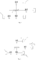
- the battery swap station control system based on wireless communication includes a master control unit 1, a state management module 2 and multiple subcontrol units 3, wherein, the master control unit 1 communicates with the state management module 2 in a wireless communication manner; and each of the subcontrol units 3 respectively communicates with the state management module 2 in a wireless communication manner.
- a hardwired connection communication manner adopted by a current battery swap station control system is replaced with a wireless communication manner, cables are saved, and the battery swap station control system is easy to maintain and flexible in networking.
- the master control unit 1 is used for transmitting a corresponding control instruction to the state management module 2 according to battery swap requirements; the state management module 2 is used for calling corresponding subcontrol units 3 according to the control instruction and controlling an operation time sequence of each subcontrol unit 3; and each of the subcontrol units 3 controls one battery swap station subsystem in real time.
- the battery swap station is divided into multiple battery swap station subsystems according to a local principle; each of the battery swap station subsystems includes multiple sensors and actuating mechanisms; communication is performed between the multiple sensors and actuating mechanisms of each battery swap station subsystem by adopting communication cables or in a wireless communication manner; and the multiple battery swap station subsystems communicate with one another in the wireless communication manner.
- each of the battery swap station subsystems comprises an RGV subsystem 4, a battery swap platform subsystem 5 and a battery compartment lift subsystem 6.
- a division manner of the battery swap station subsystems is not limited to this.
- the battery swap station subsystems may be more delicately divided according to factors such as specific control requirements, or divided in other forms.
- the battery swap station is divided into a battery swap platform subsystem, a battery pack storage subsystem, a battery pack swap subsystem, an RGV subsystem and the like.
- the sensors include a range sensor, a displacement sensor, a temperature sensor, a hydraulic sensor and the like.
- the actuating mechanisms include a lifting mechanism, a bolt tightening mechanism, a servo motor and the like.
- the various battery swap station subsystems may be continuously connected in a wired communication manner according to the local principle.
- the subcontrol units 3 corresponding to each battery swap station subsystem are connected with the master control unit 1 and the state management module 2 in a wireless communication manner.
- the mode of distributed control and centralized management is a master-slave question-answer mode.
- Each of the subcontrol units 3 is subjected to individual real-time management, for controlling corresponding battery swap station subsystems.
- the subcontrol units 3 set two task cycles, that is, a first task cycle and a second task cycle respectively; the first task cycle is smaller than the second task cycle; the first task cycle is a rapid task cycle; and priority of the first task cycle is higher than that of the second task cycle.
- the subcontrol units 3 include core registers. With the adoption of a multi-core multi-thread operating manner, hardware interfaces of the battery swap station subsystems are isochronously and constantly scanned in the first task cycle.
- the subcontrol units 3 do not need to communicate with the master control unit via system interfaces, but directly rapidly communicate in a physical scan area via hardware interfaces 10 so as to perform fault response.
- the fault response includes fault interrupt and linkage downtime among the various battery swap station subsystems, thus the real-time property and efficiency of battery swap station control are increased.
- the subcontrol units 3 receive execution start information transmitted by the state management module 2. With respect to actuating mechanisms having extremely high real-time requirements, such as servo motors of the battery swap station subsystems and the like, the subcontrol units 3 output dynamic response instructions to the battery swap station subsystems in real time so as to perform individual internal control.
- process data such as temperature, water level and the like
- a slow task cycle is opened, that is, the second task cycle.
- the process data enters the second task cycle, the process data of the battery swap station subsystems is acquired, and the process data is uploaded to the state management module 2.
- the subcontrol units perform real-time control on the battery swap station subsystems by adopting a strategy of distributed management and centralized control, opens the multithread operations to be used for responding to isochronous rapid interrupt so as to be used for responding to linkage stop and transmitting own faults, and directly come round a logical layer and a system interface to rapidly execute a hardware layer. Therefore, the control real-time property and response efficiency are increased.
- the state management module 2 includes a cache unit, used for storing data contents of the subcontrol units 3 and the master control unit 1 in one or more preset cycles in real time, wherein each preset cycle is greater than or equal to the second task cycle.
- the data contents may be set according to specific control requirements. For example, the data contents can be set as data contents within 10 cycles before real-time storage.
- the cache unit can regularly acquire the data of the master control unit 1 and each of the subcontrol units 3 in real time or in a preset time period, and sort and store the acquired data.
- the cache unit is provided with a retransmission mechanism; when the subcontrol units 3 have communication failure and perform handshake communication with the cache unit, after communication connection is established, the cache unit retransmits data contents of the corresponding subcontrol units 3 in one cycle or multiple cycles currently to the corresponding subcontrol units 3, so that the corresponding battery swap station subsystems can rapidly continue to operate.
- the state management module 2 performs interface call of the subcontrol units 3 in real time according to the state timing sequence, and transmits a real-time local task requirement.
- the cache unit includes a cache control subunit and also has node tracking resource capacity. When a battery swap station subsystem corresponding to a certain subcontrol unit 3 is located in an idle state, the cache control subunit may recover corresponding idle memory in time and control the idle memory to be used for storing control subunit data in other idle states, thereby increasing the control real-time property.
- the state management module 2 further includes a data forwarding unit, used for receiving the process data of the subcontrol units 3, collecting the process data, and forwarding the process data to the master control unit 1 so as to perform batch processing and storage.
- a data forwarding unit used for receiving the process data of the subcontrol units 3, collecting the process data, and forwarding the process data to the master control unit 1 so as to perform batch processing and storage.
- the state management module 2 is capable of dynamically and reasonably dispatching each of the subcontrol units 3, transmitting the known timing sequence according to the master control unit, and notifying the subcontrol units of memory recovery in advance. Moreover, some subcontrol units 3 can be rapidly removed under conditions that the subcontrol units are abnormal and the whole control system is not influenced. Therefore, functions such as power failure retransmission of the subcontrol units 3 and removal and re-networking of the abnormal subcontrol units 3 can be realized.
- the master control unit 1 is mainly used for allocating state maneuvering steps of the subsystems, and processing and storing the process data of each battery swap station subsystem.
- the master control unit 1 is further used for performing analytic processing on the process data and transmitting a corresponding feedback instruction.
- the master control unit 1 may perform qualitative analysis on big data in the form of process data, so as to form pre-diagnosis. For example, the master control unit 1 compares the process data with a preset process data scope. If the process data is not included in the preset process data scope, the master control unit controls to transmit an alarm signal, and control reliability is increased.
- the master control unit 1 is further used for controlling each of the subcontrol units 3 to perform clock timing synchronization during initialization. Clocks of each of the subcontrol units 3 and the master control unit 1 are controlled to be located in a synchronization state, thereby ensuring real-time response accuracy of the system and also ensuring response interrupt accuracy of each of the subcontrol units 3.
- the master control unit 1 may further actively interrupt work of a battery swap station subsystem that is located in communication jam or in an abnormal state according to an actual operation condition. Specifically, when the battery swap station subsystem is located in communication jam or in the abnormal state, the master control unit 1 transmits an interrupt control instruction to the state management module 2, wherein the interrupt control instruction includes address information of a subcontrol unit 3 corresponding to the battery swap station subsystem that is located in communication jam or in the abnormal state. The state management module 2 forwards the interrupt control instruction to the corresponding subcontrol unit 3, and the subcontrol unit 3 interrupts work of the corresponding battery swap station subsystem according to the interrupt control instruction. In the whole process, normal work of the other subcontrol units 3 is not influenced.
- Embodiments of the present invention provide the battery swap station control system based on wireless communication.
- the wired communication and the communication control manner of the slide link components are replaced with the wireless communication control manner, use of communication cables is reduced, the battery swap station control system is convenient to maintain and flexible in networking, and real-time control efficiency of the battery swap station is increased.
- the subcontrol units perform real-time control on the corresponding battery swap station subsystems, open isochronous rapid interrupt to be used for responding to linkage stop and transmitting own faults, directly come round the logical layer and the system interface to rapidly execute the hardware layer, and open the multithread operations to be specially used for responding to fault interrupt and linkage stop; the master control unit processes and stores the state of each subcontrol unit and the process data.
- the subcontrol unit corresponding to each battery swap station subsystem interacts with the state timing sequence of the master control unit so as to form distributed control and centralized management, and the real-time property and reliability of the battery swap station control are increased; moreover, the state management module is increased between the master control unit and the subcontrol units, thus dispatching of each subcontrol unit can be dynamically and reasonably utilized, the known timing sequence is transmitted according to the master control unit, the subcontrol units are notified of the memory recovery in advance, and some subcontrol units can be rapidly removed under the condition that the subcontrol units are abnormal and the whole system is not influenced.
- the wireless state communication rate is increased.
- Embodiments of the present invention further provide a battery swap station.
- the battery swap station includes any of the battery swap station control systems in the above examples, and further includes multiple battery swap station subsystems.
- the battery swap station control system includes a master control unit 1, a state management module 2 and multiple subcontrol units 3.
- the master control unit 1 is used for transmitting a corresponding control instruction to the state management module 2 according to battery swap requirements;
- the state management module 2 is used for calling corresponding subcontrol units 3 according to the control instruction and controlling an operation time sequence of each subcontrol unit 3; and each of the subcontrol units 3 controls one battery swap station subsystem in real time.
- the battery swap station is divided into multiple battery swap station subsystems according to a local principle; each of the battery swap station subsystems includes multiple sensors and actuating mechanisms; communication is performed between the multiple sensors and actuating mechanisms of each battery swap station subsystem by adopting communication cables or in a wireless communication manner; and the multiple battery swap station subsystems communicate with one another in the wireless communication manner.
- Each of the battery swap station subsystems includes an RGV subsystem 4, a battery swap platform subsystem 5 and a battery compartment lift subsystem 6.
- a division manner of the battery swap station subsystems is not limited to this.
- the battery swap station subsystems may be more delicately divided according to factors such as specific control requirements, or divided in other forms.
- the battery swap station is divided into a battery swap platform subsystem, a battery pack storage subsystem, a battery pack swap subsystem, an RGV subsystem and the like.
- the sensors include a range sensor, a displacement sensor, a temperature sensor, a hydraulic sensor and the like.
- the actuating mechanisms include a lifting mechanism, a bolt tightening mechanism, a servo motor and the like.
- the various battery swap station subsystems may be continuously connected in a wired communication manner according to the local principle.
- the subcontrol units 3 corresponding to each battery swap station subsystem are connected with the master control unit 1 and the state management module 2 in a wireless communication manner.
- the mode of distributed control and centralized management is a master-slave question-answer mode.
- the wired communication and the communication control manner of the slide link components are replaced with the wireless communication control manner, the use of communication cables is reduced, and the battery swap station control system is convenient to maintain and flexible in networking; the control system adopts the manner of distributed control and centralized management, so that the various components of the battery swap station are subjected to coordinated control, and the real-time control efficiency of the battery swap station is increased, thereby increasing the battery swap efficiency and improving the user experience.
Landscapes
- Engineering & Computer Science (AREA)
- Power Engineering (AREA)
- Transportation (AREA)
- Mechanical Engineering (AREA)
- Remote Monitoring And Control Of Power-Distribution Networks (AREA)
- Mobile Radio Communication Systems (AREA)
- Power Sources (AREA)
Abstract
Description
- The present invention relates to the technical field of control of battery swap stations, in particular to a battery swap station control system based on wireless communication and a battery swap station.
- With the supply pressure brought by the traditional fossil energy consumption and exhaust pollution, energy-saving and environment-friendly electric vehicles present blowout development in recent years. Since development of the electric vehicles is limited by a battery technology, limited battery capacity and long charging time are inevitable questions at the present stage. However, in many charging ways, a battery swap way is a rapid, convenient and safe method.
- A battery swap station is composed of a parking platform, a battery pick-and-replace trolley, a battery compartment storage charging rack, a battery compartment lift and other auxiliary equipment. A battery swap process is completed by unified collaboration of these components. Each component respectively includes multiple actuating mechanisms. Generally, actions of these actuating mechanisms are controlled by servo motors and the like, so an existing battery swap station control system has characteristics as follows: (1) the control system is provided with multiple sensor inputs, and remote communication slave stations of multiple output actuating components; and (2) the control system is provided with an RGV (rail guide vehicle) and other mobile components. Based on the above characteristics, the existing battery swap station control system has defects that communication cables are numerous and are easy to damage, multiple in failure nodes and difficult to maintain and slide links of the mobile components are easily damaged and needs to be frequently replaced.
- Technical problems to be solved in the present invention are to provide a battery swap station control system based on wireless communication and a battery swap station. Wired communication and a communication control manner of slide link components are replaced with a wireless communication control manner, a control method for distributed control and centralized management is adopted, and real-time property and reliability of battery swap station control are increased.
- In order to solve the aforementioned technical problems, one aspect of the present invention provides the battery swap station control system based on wireless communication, including: a master control unit, a state management module and multiple subcontrol units,
wherein, the master control unit communicates with the state management module in a wireless communication manner; and each of the subcontrol units respectively communicates with the state management module in a wireless communication manner;
the master control unit is used for transmitting a corresponding control instruction to the state management module according to battery swap requirements;
the state management module is used for calling corresponding subcontrol units according to the control instruction and controlling an operation time sequence of each subcontrol unit; and
each of the subcontrol units controls one battery swap station subsystem in real time. - Further, the subcontrol units set two task cycles, that is, a first task cycle and a second task cycle respectively. The first task cycle is smaller than the second task cycle; in the first task cycle, dynamic response instructions are output to actuating mechanisms of the battery swap station subsystems in real time so as to perform individual internal control;
when the first task cycle is located in an idle condition, the battery swap station subsystems enter the second task cycle, process data of the battery swap station subsystems is acquired, and the process data is uploaded to the state management module. - Further, the subcontrol units include core registers. Hardware interfaces of the battery swap station subsystems are scanned in the first task cycle in a multi-core and multithreaded manner, and if hardware faults of the battery swap station subsystems occur, the subcontrol units directly perform fault response.
- Further, the fault response includes fault interrupt and linkage downtime among the various battery swap station subsystems.
- Further, the process data includes temperature and water level.
- Further, the state management module includes a cache unit, used for storing data contents of the subcontrol units and the master control unit in one or more preset cycles in real time, wherein each preset cycle is greater than the second task cycle.
- Further, the cache unit is provided with a retransmission mechanism. When the subcontrol units have communication failure, after communication connection is established between the subcontrol units and the cache unit, the cache unit transmits data contents of the subcontrol units in one cycle or multiple cycles currently to the subcontrol units.
- Further, the cache unit includes a cache control subunit. When a battery swap station subsystem corresponding to a certain subcontrol unit is located in an idle state, the cache control subunit recovers corresponding idle memory and controls the idle memory to be used for storing control subunit data in other idle states.
- Further, the state management module further includes a data forwarding unit, used for receiving the process data and forwarding the process data to the master control unit.
- Further, the master control unit is further used for performing analytic processing on the process data and transmitting a corresponding feedback instruction.
- Further, the master control unit compares the process data with a preset process data scope, and if the process data is not included in the preset process data scope, the master control unit controls to transmit an alarm signal.
- Further, the master control unit is further used for controlling each of the subcontrol units to perform clock timing synchronization during initialization.
- Further, the master control unit is further used for interrupting work of a battery swap station subsystem that is located in communication jam or in an abnormal state.
- Further, the battery swap station is divided into multiple battery swap station subsystems according to a local principle; each of the battery swap station subsystems includes multiple sensors and actuating mechanisms; communication is performed between the multiple sensors and actuating mechanisms of each battery swap station subsystem by adopting communication cables or in a wireless communication manner; the multiple battery swap station subsystems communicate with one another in the wireless communication manner.
- Further, each of the battery swap station subsystems includes an RGV subsystem, a battery swap platform subsystem and a battery compartment lift subsystem.
- Another aspect of the present invention provides a battery swap station, including the aforementioned battery swap station control system and battery swap station subsystems.
- Further, each of the battery swap station subsystems includes an RGV subsystem, a battery swap platform subsystem and a battery compartment lift subsystem.
- Compared with the prior art, the present invention has obvious advantages and beneficial effects. By virtue of the aforementioned technical solutions, the battery swap station control system based on wireless communication and the battery swap station in the present invention may achieve considerable technological progress and practicality, have industrialized extensive utilization values, and at least have the following advantages:
- (1) in the present invention, the wired communication and the communication control manner of the slide link components are replaced with the wireless communication control manner, use of communication cables is reduced, the battery swap station control system is convenient to maintain and flexible in networking, and real-time control efficiency of the battery swap station is increased;
- (2) compared with the traditional wireless control, since control of position loops and speed loops of motors and the like needs an extremely high real-time control requirement, the subcontrol units perform real-time control on corresponding battery swap station subsystems, open isochronous rapid interrupt to be used for responding to linkage stop and transmitting own faults, directly come round a logical layer and a system interface to rapidly execute a hardware layer, and open multithread operations to be specially used for responding to fault interrupt and linkage stop;
the master control unit processes and stores the state of each subcontrol unit and the process data. The subcontrol unit corresponding to each battery swap station subsystem interacts with the state timing sequence of the master control unit so as to form distributed control and centralized management, and the real-time property and reliability of the battery swap station control are increased; - (3) the state management module is increased between the master control unit and the subcontrol units, dispatching of each subcontrol unit can be dynamically and reasonably utilized, the known timing sequence is transmitted according to the master control unit, the subcontrol units are notified of memory recovery in advance, and some subcontrol units can be rapidly removed under conditions that the subcontrol units are abnormal and the whole system is not influenced;
- (4) in the present invention, in a state of meeting motion control requirements, a wireless state communication rate is increased.
- The above description is only an overview of the technical solutions of the present invention. In order to understand the technical means of the present invention more clearly, the present invention can be implemented in accordance with the contents of the specification, and in order to make the above and other objects, features and advantages of the present invention more obvious and understandable, preferred embodiments are listed below and are described in detail below in combination with drawings
-
-
Fig. 1 is a schematic diagram of a battery swap station control system based on wireless communication provided by one embodiment of the present invention; -
Fig. 2 is a schematic diagram of a battery swap station provided by one embodiment of the present invention. - In order to further illustrate the technical means and effects adopted in the present invention to achieve the intended purpose of the invention, specific embodiments and effects of a battery swap station control system based on wireless communication and a battery swap station proposed in accordance with the present invention are described in detail below, in conjunction with the drawings and preferred embodiments.
- As shown in
Fig. 1 , the battery swap station control system based on wireless communication includes amaster control unit 1, astate management module 2 andmultiple subcontrol units 3, wherein, themaster control unit 1 communicates with thestate management module 2 in a wireless communication manner; and each of thesubcontrol units 3 respectively communicates with thestate management module 2 in a wireless communication manner. In the present invention, a hardwired connection communication manner adopted by a current battery swap station control system is replaced with a wireless communication manner, cables are saved, and the battery swap station control system is easy to maintain and flexible in networking. Themaster control unit 1 is used for transmitting a corresponding control instruction to thestate management module 2 according to battery swap requirements; thestate management module 2 is used for callingcorresponding subcontrol units 3 according to the control instruction and controlling an operation time sequence of eachsubcontrol unit 3; and each of thesubcontrol units 3 controls one battery swap station subsystem in real time. - In the example as shown in
Fig. 2 , the battery swap station is divided into multiple battery swap station subsystems according to a local principle; each of the battery swap station subsystems includes multiple sensors and actuating mechanisms; communication is performed between the multiple sensors and actuating mechanisms of each battery swap station subsystem by adopting communication cables or in a wireless communication manner; and the multiple battery swap station subsystems communicate with one another in the wireless communication manner. InFig. 2 , each of the battery swap station subsystems comprises an RGV subsystem 4, a battery swap platform subsystem 5 and a batterycompartment lift subsystem 6. However, it is understandable that, a division manner of the battery swap station subsystems is not limited to this. The battery swap station subsystems may be more delicately divided according to factors such as specific control requirements, or divided in other forms. For example, the battery swap station is divided into a battery swap platform subsystem, a battery pack storage subsystem, a battery pack swap subsystem, an RGV subsystem and the like. The sensors include a range sensor, a displacement sensor, a temperature sensor, a hydraulic sensor and the like. The actuating mechanisms include a lifting mechanism, a bolt tightening mechanism, a servo motor and the like. - The various battery swap station subsystems may be continuously connected in a wired communication manner according to the local principle. The
subcontrol units 3 corresponding to each battery swap station subsystem are connected with themaster control unit 1 and thestate management module 2 in a wireless communication manner. With the adoption of a control mode of distributed control and centralized management, real-time control efficiency is increased. The mode of distributed control and centralized management is a master-slave question-answer mode. By taking the subcontrol units as local control units of the battery swap station subsystems, response implementation is ensured, and according to synchronous call of the master control unit, the timing sequence is entirely controlled so as to meet the battery swap requirement. - Components of the battery swap station control system are respectively described below:
- Each of the
subcontrol units 3 is subjected to individual real-time management, for controlling corresponding battery swap station subsystems. Thesubcontrol units 3 set two task cycles, that is, a first task cycle and a second task cycle respectively; the first task cycle is smaller than the second task cycle; the first task cycle is a rapid task cycle; and priority of the first task cycle is higher than that of the second task cycle. Thesubcontrol units 3 include core registers. With the adoption of a multi-core multi-thread operating manner, hardware interfaces of the battery swap station subsystems are isochronously and constantly scanned in the first task cycle. If hardware faults of the battery swap station subsystems occur, thesubcontrol units 3 do not need to communicate with the master control unit via system interfaces, but directly rapidly communicate in a physical scan area via hardware interfaces 10 so as to perform fault response. The fault response includes fault interrupt and linkage downtime among the various battery swap station subsystems, thus the real-time property and efficiency of battery swap station control are increased. - In the first task cycle, the
subcontrol units 3 receive execution start information transmitted by thestate management module 2. With respect to actuating mechanisms having extremely high real-time requirements, such as servo motors of the battery swap station subsystems and the like, thesubcontrol units 3 output dynamic response instructions to the battery swap station subsystems in real time so as to perform individual internal control. For process data such as temperature, water level and the like, a slow task cycle is opened, that is, the second task cycle. When the first task cycle is located in an idle condition, the process data enters the second task cycle, the process data of the battery swap station subsystems is acquired, and the process data is uploaded to thestate management module 2. - Since control of position loops and speed loops of motors and the like needs an extremely high real-time control requirement, the subcontrol units perform real-time control on the battery swap station subsystems by adopting a strategy of distributed management and centralized control, opens the multithread operations to be used for responding to isochronous rapid interrupt so as to be used for responding to linkage stop and transmitting own faults, and directly come round a logical layer and a system interface to rapidly execute a hardware layer. Therefore, the control real-time property and response efficiency are increased.
- The
state management module 2 includes a cache unit, used for storing data contents of thesubcontrol units 3 and themaster control unit 1 in one or more preset cycles in real time, wherein each preset cycle is greater than or equal to the second task cycle. The data contents may be set according to specific control requirements. For example, the data contents can be set as data contents within 10 cycles before real-time storage. The cache unit can regularly acquire the data of themaster control unit 1 and each of thesubcontrol units 3 in real time or in a preset time period, and sort and store the acquired data. - The cache unit is provided with a retransmission mechanism; when the
subcontrol units 3 have communication failure and perform handshake communication with the cache unit, after communication connection is established, the cache unit retransmits data contents of thecorresponding subcontrol units 3 in one cycle or multiple cycles currently to thecorresponding subcontrol units 3, so that the corresponding battery swap station subsystems can rapidly continue to operate. - The
state management module 2 performs interface call of thesubcontrol units 3 in real time according to the state timing sequence, and transmits a real-time local task requirement. The cache unit includes a cache control subunit and also has node tracking resource capacity. When a battery swap station subsystem corresponding to acertain subcontrol unit 3 is located in an idle state, the cache control subunit may recover corresponding idle memory in time and control the idle memory to be used for storing control subunit data in other idle states, thereby increasing the control real-time property. - The
state management module 2 further includes a data forwarding unit, used for receiving the process data of thesubcontrol units 3, collecting the process data, and forwarding the process data to themaster control unit 1 so as to perform batch processing and storage. - The
state management module 2 is capable of dynamically and reasonably dispatching each of thesubcontrol units 3, transmitting the known timing sequence according to the master control unit, and notifying the subcontrol units of memory recovery in advance. Moreover, somesubcontrol units 3 can be rapidly removed under conditions that the subcontrol units are abnormal and the whole control system is not influenced. Therefore, functions such as power failure retransmission of thesubcontrol units 3 and removal and re-networking of theabnormal subcontrol units 3 can be realized. - The
master control unit 1 is mainly used for allocating state maneuvering steps of the subsystems, and processing and storing the process data of each battery swap station subsystem. - The
master control unit 1 is further used for performing analytic processing on the process data and transmitting a corresponding feedback instruction. Themaster control unit 1 may perform qualitative analysis on big data in the form of process data, so as to form pre-diagnosis. For example, themaster control unit 1 compares the process data with a preset process data scope. If the process data is not included in the preset process data scope, the master control unit controls to transmit an alarm signal, and control reliability is increased. - The
master control unit 1 is further used for controlling each of thesubcontrol units 3 to perform clock timing synchronization during initialization. Clocks of each of thesubcontrol units 3 and themaster control unit 1 are controlled to be located in a synchronization state, thereby ensuring real-time response accuracy of the system and also ensuring response interrupt accuracy of each of thesubcontrol units 3. - The
master control unit 1 may further actively interrupt work of a battery swap station subsystem that is located in communication jam or in an abnormal state according to an actual operation condition. Specifically, when the battery swap station subsystem is located in communication jam or in the abnormal state, themaster control unit 1 transmits an interrupt control instruction to thestate management module 2, wherein the interrupt control instruction includes address information of asubcontrol unit 3 corresponding to the battery swap station subsystem that is located in communication jam or in the abnormal state. Thestate management module 2 forwards the interrupt control instruction to thecorresponding subcontrol unit 3, and thesubcontrol unit 3 interrupts work of the corresponding battery swap station subsystem according to the interrupt control instruction. In the whole process, normal work of theother subcontrol units 3 is not influenced. - Embodiments of the present invention provide the battery swap station control system based on wireless communication. The wired communication and the communication control manner of the slide link components are replaced with the wireless communication control manner, use of communication cables is reduced, the battery swap station control system is convenient to maintain and flexible in networking, and real-time control efficiency of the battery swap station is increased. In addition, compared with the traditional wireless control, since control of the position loops and speed loops of motors and the like needs the extremely high real-time control requirement, the subcontrol units perform real-time control on the corresponding battery swap station subsystems, open isochronous rapid interrupt to be used for responding to linkage stop and transmitting own faults, directly come round the logical layer and the system interface to rapidly execute the hardware layer, and open the multithread operations to be specially used for responding to fault interrupt and linkage stop; the master control unit processes and stores the state of each subcontrol unit and the process data. The subcontrol unit corresponding to each battery swap station subsystem interacts with the state timing sequence of the master control unit so as to form distributed control and centralized management, and the real-time property and reliability of the battery swap station control are increased; moreover, the state management module is increased between the master control unit and the subcontrol units, thus dispatching of each subcontrol unit can be dynamically and reasonably utilized, the known timing sequence is transmitted according to the master control unit, the subcontrol units are notified of the memory recovery in advance, and some subcontrol units can be rapidly removed under the condition that the subcontrol units are abnormal and the whole system is not influenced. In the present invention, in the state of meeting motion control requirements, the wireless state communication rate is increased.
- Embodiments of the present invention further provide a battery swap station. As shown in
Fig. 2 , the battery swap station includes any of the battery swap station control systems in the above examples, and further includes multiple battery swap station subsystems. The battery swap station control system includes amaster control unit 1, astate management module 2 andmultiple subcontrol units 3. Themaster control unit 1 is used for transmitting a corresponding control instruction to thestate management module 2 according to battery swap requirements; thestate management module 2 is used for callingcorresponding subcontrol units 3 according to the control instruction and controlling an operation time sequence of eachsubcontrol unit 3; and each of thesubcontrol units 3 controls one battery swap station subsystem in real time. - In the example as shown in
Fig. 2 , the battery swap station is divided into multiple battery swap station subsystems according to a local principle; each of the battery swap station subsystems includes multiple sensors and actuating mechanisms; communication is performed between the multiple sensors and actuating mechanisms of each battery swap station subsystem by adopting communication cables or in a wireless communication manner; and the multiple battery swap station subsystems communicate with one another in the wireless communication manner. Each of the battery swap station subsystems includes an RGV subsystem 4, a battery swap platform subsystem 5 and a batterycompartment lift subsystem 6. However, it is understandable that, a division manner of the battery swap station subsystems is not limited to this. The battery swap station subsystems may be more delicately divided according to factors such as specific control requirements, or divided in other forms. For example, the battery swap station is divided into a battery swap platform subsystem, a battery pack storage subsystem, a battery pack swap subsystem, an RGV subsystem and the like. The sensors include a range sensor, a displacement sensor, a temperature sensor, a hydraulic sensor and the like. The actuating mechanisms include a lifting mechanism, a bolt tightening mechanism, a servo motor and the like. - The various battery swap station subsystems may be continuously connected in a wired communication manner according to the local principle. The
subcontrol units 3 corresponding to each battery swap station subsystem are connected with themaster control unit 1 and thestate management module 2 in a wireless communication manner. With the adoption of a control mode of distributed control and centralized management, real-time control efficiency is increased. The mode of distributed control and centralized management is a master-slave question-answer mode. By taking the subcontrol units as local control units of the battery swap station subsystems, response implementation is ensured, and according to synchronous call of the master control unit, the timing sequence is entirely controlled so as to meet the battery swap requirement - Among the various battery swap station subsystems of the battery swap station, the wired communication and the communication control manner of the slide link components are replaced with the wireless communication control manner, the use of communication cables is reduced, and the battery swap station control system is convenient to maintain and flexible in networking; the control system adopts the manner of distributed control and centralized management, so that the various components of the battery swap station are subjected to coordinated control, and the real-time control efficiency of the battery swap station is increased, thereby increasing the battery swap efficiency and improving the user experience.
- The above descriptions are only the preferred embodiments of the present invention, and do not limit the present invention in any form. Although the present invention has been disclosed in the preferred embodiments as above, the preferred embodiments are not used for limiting the present invention, anyone skilled familiar with this art can make some changes or modifications by using the technical contents disclosed above to serve as equivalent embodiments of equivalent changes, without departing from the scope of the technical solutions of the present invention, and any simple modifications, equivalent changes and modifications made to the above embodiments according to the technical essence of the present invention, without departing from the contents of the technical solutions of the present invention, still fall within the scope of the technical solutions of the present invention.
| 1: | master control unit | 2: | state management module |
| 3: | subcontrol unit | 4: | RGV subsystem |
| 5: | battery swap platform subsystem | 6: | battery compartment lift subsystem |
Claims (17)
- A battery swap station control system based on wireless communication, comprising: a master control unit, a state management module and multiple subcontrol units,
wherein, the master control unit communicates with the state management module in a wireless communication manner; and each of the subcontrol units respectively communicates with the state management module in a wireless communication manner;
the master control unit is used for transmitting a corresponding control instruction to the state management module according to battery swap requirements;
the state management module is used for calling corresponding subcontrol units according to the control instruction and controlling an operation time sequence of each subcontrol unit; and each of the subcontrol units controls one battery swap station subsystem in real time. - The battery swap station control system based on wireless communication according to claim 1, wherein the subcontrol units set two task cycles, that is, a first task cycle and a second task cycle respectively; the first task cycle is smaller than the second task cycle; in the first task cycle, dynamic response instructions are output to actuating mechanisms of the battery swap station subsystems in real time so as to perform individual internal control;
and when the first task cycle is located in an idle condition, the battery swap station subsystems enter the second task cycle, process data of the battery swap station subsystems is acquired, and the process data is uploaded to the state management module. - The battery swap station control system based on wireless communication according to claim 2, wherein the subcontrol units comprise core registers; hardware interfaces of the battery swap station subsystems are scanned in the first task cycle in a multi-core and multithreaded manner, and if hardware faults of the battery swap station subsystems occur, the subcontrol units directly perform fault response.
- The battery swap station control system based on wireless communication according to claim 3, wherein the fault response comprises fault interrupt and linkage downtime among the various battery swap station subsystems.
- The battery swap station control system based on wireless communication according to claim 2, wherein the process data comprises temperature and water level.
- The battery swap station control system based on wireless communication according to claim 2, wherein the state management module comprises a cache unit, used for storing data contents of the subcontrol units and the master control unit in one or more preset cycles in real time, wherein each preset cycle is greater than the second task cycle.
- The battery swap station control system based on wireless communication according to claim 6, wherein the cache unit is provided with a retransmission mechanism; when the subcontrol units have communication failure, after communication connection is established between the subcontrol units and the cache unit, the cache unit transmits data contents of the subcontrol units in one cycle or multiple cycles currently to the subcontrol units.
- The battery swap station control system based on wireless communication according to claim 6, wherein the cache unit comprises a cache control subunit; when a battery swap station subsystem corresponding to a certain subcontrol unit is located in an idle state, the cache control subunit recovers corresponding idle memory and controls the idle memory to be used for storing control subunit data in other idle states.
- The battery swap station control system based on wireless communication according to claim 2, wherein the state management module further comprises a data forwarding unit, used for receiving the process data and forwarding the process data to the master control unit.
- The battery swap station control system based on wireless communication according to claim 2, wherein the master control unit is further used for performing analytic processing on the process data and transmitting a corresponding feedback instruction.
- The battery swap station control system based on wireless communication according to claim 10, wherein the master control unit compares the process data with a preset process data scope, and if the process data is not included in the preset process data scope, the master control unit controls to transmit an alarm signal.
- The battery swap station control system based on wireless communication according to claim 1, wherein the master control unit is further used for controlling each of the subcontrol units to perform clock timing synchronization during initialization.
- The battery swap station control system based on wireless communication according to claim 1, wherein the master control unit is further used for interrupting work of a battery swap station subsystem that is located in communication jam or in an abnormal state.
- The battery swap station control system based on wireless communication according to any one of claims 1-13, wherein the battery swap station is divided into multiple battery swap station subsystems according to a local principle; each of the battery swap station subsystems includes multiple sensors and actuating mechanisms; communication is performed between the multiple sensors and actuating mechanisms of each battery swap station subsystem by adopting communication cables or in a wireless communication manner; the multiple battery swap station subsystems communicate with one another in the wireless communication manner.
- The battery swap station control system based on wireless communication according to claim 14, wherein each of the battery swap station subsystems comprises an RGV subsystem, a battery swap platform subsystem and a battery compartment lift subsystem.
- A battery swap station, comprising: the battery swap station control system according to any one of claims 1-15, and further comprising multiple battery swap station subsystems.
- The battery swap station according to claim 16, wherein each of the battery swap station subsystems comprises an RGV subsystem, a battery swap platform subsystem and a battery compartment lift subsystem.
Applications Claiming Priority (2)
| Application Number | Priority Date | Filing Date | Title |
|---|---|---|---|
| CN201711216951.2A CN108400652B (en) | 2017-11-28 | 2017-11-28 | Wireless communication-based control system and power exchange station |
| PCT/CN2018/103260 WO2019105081A1 (en) | 2017-11-28 | 2018-08-30 | Battery-swapping station control system based on wireless communication and battery-swapping station |
Publications (2)
| Publication Number | Publication Date |
|---|---|
| EP3719955A1 true EP3719955A1 (en) | 2020-10-07 |
| EP3719955A4 EP3719955A4 (en) | 2021-05-19 |
Family
ID=63094280
Family Applications (1)
| Application Number | Title | Priority Date | Filing Date |
|---|---|---|---|
| EP18882699.4A Pending EP3719955A4 (en) | 2017-11-28 | 2018-08-30 | BATTERY SWAP STATION CONTROL SYSTEM BASED ON WIRELESS COMMUNICATION AND BATTERY SWAP STATION |
Country Status (3)
| Country | Link |
|---|---|
| EP (1) | EP3719955A4 (en) |
| CN (1) | CN108400652B (en) |
| WO (1) | WO2019105081A1 (en) |
Cited By (1)
| Publication number | Priority date | Publication date | Assignee | Title |
|---|---|---|---|---|
| EP4120505A1 (en) * | 2021-07-16 | 2023-01-18 | Gogoro Inc. | Battery exchange method and battery exchange system |
Families Citing this family (4)
| Publication number | Priority date | Publication date | Assignee | Title |
|---|---|---|---|---|
| CN108400652B (en) * | 2017-11-28 | 2020-11-06 | 蔚来(安徽)控股有限公司 | Wireless communication-based control system and power exchange station |
| CN109448349B (en) * | 2018-11-22 | 2021-12-28 | 广州南湾信息科技有限公司 | Hydrological telemetering equipment |
| CN110053511A (en) * | 2019-05-05 | 2019-07-26 | 广州市旋通节能科技有限公司 | The Intelligent management control system of electricity is changed in a kind of electric ship charging |
| CN111263385B (en) * | 2020-01-19 | 2023-02-28 | 深圳拓邦股份有限公司 | Charging and battery replacing cabinet and communication method thereof |
Family Cites Families (14)
| Publication number | Priority date | Publication date | Assignee | Title |
|---|---|---|---|---|
| DE102009053050A1 (en) * | 2009-11-16 | 2011-05-19 | Siemens Aktiengesellschaft | Method and device for exchanging a battery in a vehicle |
| KR20120062089A (en) * | 2010-12-06 | 2012-06-14 | 한국전자통신연구원 | Vehicle mobile gateway for controling charging of electric vehicle using mobile terminal, electric vehicle having the same, and method for controling charging of electric vehicle using mobile terminal |
| CN202043250U (en) * | 2011-05-26 | 2011-11-16 | 山东鲁能智能技术有限公司 | Video surveillance system of electric vehicle charging and switching station |
| JP5505373B2 (en) * | 2011-06-17 | 2014-05-28 | 横河電機株式会社 | COMMUNICATION SYSTEM, COMMUNICATION DEVICE, AND COMMUNICATION METHOD |
| CN105140977B (en) * | 2014-05-29 | 2017-09-05 | 国家电网公司 | Electric automobile based on dispatching of power netwoks changes method for electrically and changes electricity service Internet of Things |
| CN105182884B (en) * | 2015-10-13 | 2018-06-12 | 中国矿业大学 | A kind of new-energy automobile charging and conversion electric facility remote monitoring system and method |
| CN105667464A (en) * | 2016-03-18 | 2016-06-15 | 蔚来汽车有限公司 | Electric vehicle battery replacement system and method based on cloud storage |
| US9873408B2 (en) * | 2016-05-11 | 2018-01-23 | Peter D. Capizzo | Device for refueling, exchanging, and charging power sources on remote controlled vehicles, UAVs, drones, or any type of robotic vehicle or machine with mobility |
| CN106532806B (en) * | 2016-10-21 | 2020-06-09 | 国网山东省电力公司电力科学研究院 | A kind of intelligent power exchange control method and system for electric vehicle charging and exchanging station |
| CN106882163A (en) * | 2017-01-13 | 2017-06-23 | 上海蔚来汽车有限公司 | The Modular control system and its control method of electric automobile charging station |
| CN106681220A (en) * | 2017-01-13 | 2017-05-17 | 上海蔚来汽车有限公司 | Battery swap action control system based on central processing unit and programmable logic device |
| CN107161020B (en) * | 2017-05-15 | 2020-10-23 | 上海蔚来汽车有限公司 | Charging and battery replacing station and charging and battery replacing control system |
| CN107277158A (en) * | 2017-07-06 | 2017-10-20 | 上海蔚来汽车有限公司 | Electric charging station monitoring system and electric charging station based on B/S frameworks |
| CN108400652B (en) * | 2017-11-28 | 2020-11-06 | 蔚来(安徽)控股有限公司 | Wireless communication-based control system and power exchange station |
-
2017
- 2017-11-28 CN CN201711216951.2A patent/CN108400652B/en active Active
-
2018
- 2018-08-30 WO PCT/CN2018/103260 patent/WO2019105081A1/en not_active Ceased
- 2018-08-30 EP EP18882699.4A patent/EP3719955A4/en active Pending
Cited By (2)
| Publication number | Priority date | Publication date | Assignee | Title |
|---|---|---|---|---|
| EP4120505A1 (en) * | 2021-07-16 | 2023-01-18 | Gogoro Inc. | Battery exchange method and battery exchange system |
| JP2023014007A (en) * | 2021-07-16 | 2023-01-26 | ゴゴロ インク | Battery exchange method and battery exchange system |
Also Published As
| Publication number | Publication date |
|---|---|
| WO2019105081A9 (en) | 2020-07-16 |
| CN108400652A (en) | 2018-08-14 |
| CN108400652B (en) | 2020-11-06 |
| EP3719955A4 (en) | 2021-05-19 |
| WO2019105081A1 (en) | 2019-06-06 |
Similar Documents
| Publication | Publication Date | Title |
|---|---|---|
| EP3719955A1 (en) | Battery-swapping station control system based on wireless communication and battery-swapping station | |
| CN101776711B (en) | Electric energy metering system substation | |
| WO2018210015A1 (en) | Battery charge/swap station and battery charge/swap control system | |
| CN203398797U (en) | Multi-machine parallel control system of dual-mode energy storing device | |
| CN107386868B (en) | A kind of modular control apparatus for platform door system | |
| CN105356432B (en) | More contact distribution network failure dead electricity region topology identifying systems and method based on Multi Agent | |
| CN101877528A (en) | Dual CPU redundant fault-tolerant system based on high-voltage frequency converter and its realization method | |
| CN113592256B (en) | Train operation plan adjustment method and system based on charging station faults | |
| CN111031597A (en) | An AGV low-power standby communication circuit and its working method | |
| CN102866698B (en) | Human machine interface (HMI) redundant communication method for distributed control system controller | |
| CN118938639A (en) | A dual redundant control device and switching method for ship energy management system | |
| CN112186077B (en) | An intelligent manufacturing control system for a solar cell plant | |
| CN103885422B (en) | Hydrogen fuel stand-by power supply monitoring system and method | |
| CN103186130B (en) | The EMS of power transmission state monitoring solar power supply unit and method | |
| CN106828356B (en) | Two-way CAN communication method and module for electric vehicle power system | |
| CN202080698U (en) | Automatic control system of precision transmission equipment | |
| CN201674386U (en) | Dual CPU Redundant Fault Tolerance System Based on High Voltage Frequency Converter | |
| CN111490936A (en) | IEC61850 redundant device access method and system based on communication link management | |
| CN102419555A (en) | Electric automobile state simulation method based on petri net | |
| CN101804725A (en) | Software and hardware combination multi-grade exception processing method of full-automatic precise screen printer | |
| CN101786453A (en) | Interactive control method of double congruent central coordinators | |
| CN202503303U (en) | Automatic management system of ship power station | |
| CN104125595A (en) | Fault location and isolation method and detection equipment | |
| CN107479484A (en) | A kind of gas holder control system and method | |
| CN105024845B (en) | A kind of wind power plant integrated terminal redundancy approach |
Legal Events
| Date | Code | Title | Description |
|---|---|---|---|
| STAA | Information on the status of an ep patent application or granted ep patent |
Free format text: STATUS: THE INTERNATIONAL PUBLICATION HAS BEEN MADE |
|
| PUAI | Public reference made under article 153(3) epc to a published international application that has entered the european phase |
Free format text: ORIGINAL CODE: 0009012 |
|
| STAA | Information on the status of an ep patent application or granted ep patent |
Free format text: STATUS: REQUEST FOR EXAMINATION WAS MADE |
|
| 17P | Request for examination filed |
Effective date: 20200629 |
|
| AK | Designated contracting states |
Kind code of ref document: A1 Designated state(s): AL AT BE BG CH CY CZ DE DK EE ES FI FR GB GR HR HU IE IS IT LI LT LU LV MC MK MT NL NO PL PT RO RS SE SI SK SM TR |
|
| AX | Request for extension of the european patent |
Extension state: BA ME |
|
| RAP1 | Party data changed (applicant data changed or rights of an application transferred) |
Owner name: NIO (ANHUI) HOLDING CO., LTD. |
|
| RIN1 | Information on inventor provided before grant (corrected) |
Inventor name: JIA, LEI |
|
| DAV | Request for validation of the european patent (deleted) | ||
| DAX | Request for extension of the european patent (deleted) | ||
| A4 | Supplementary search report drawn up and despatched |
Effective date: 20210421 |
|
| RIC1 | Information provided on ipc code assigned before grant |
Ipc: H02J 13/00 20060101AFI20210415BHEP Ipc: H02J 7/00 20060101ALI20210415BHEP Ipc: B60L 53/80 20190101ALI20210415BHEP Ipc: B60L 53/30 20190101ALI20210415BHEP |