EP3719948A1 - System for quench protection of superconducting machines, such as a superconducting wind turbine generator - Google Patents
System for quench protection of superconducting machines, such as a superconducting wind turbine generator Download PDFInfo
- Publication number
- EP3719948A1 EP3719948A1 EP20164284.0A EP20164284A EP3719948A1 EP 3719948 A1 EP3719948 A1 EP 3719948A1 EP 20164284 A EP20164284 A EP 20164284A EP 3719948 A1 EP3719948 A1 EP 3719948A1
- Authority
- EP
- European Patent Office
- Prior art keywords
- superconducting
- heater
- quench
- coils
- switch
- Prior art date
- Legal status (The legal status is an assumption and is not a legal conclusion. Google has not performed a legal analysis and makes no representation as to the accuracy of the status listed.)
- Granted
Links
Images

Classifications
-
- H—ELECTRICITY
- H01—ELECTRIC ELEMENTS
- H01F—MAGNETS; INDUCTANCES; TRANSFORMERS; SELECTION OF MATERIALS FOR THEIR MAGNETIC PROPERTIES
- H01F6/00—Superconducting magnets; Superconducting coils
- H01F6/02—Quenching; Protection arrangements during quenching
-
- H—ELECTRICITY
- H02—GENERATION; CONVERSION OR DISTRIBUTION OF ELECTRIC POWER
- H02K—DYNAMO-ELECTRIC MACHINES
- H02K11/00—Structural association of dynamo-electric machines with electric components or with devices for shielding, monitoring or protection
- H02K11/20—Structural association of dynamo-electric machines with electric components or with devices for shielding, monitoring or protection for measuring, monitoring, testing, protecting or switching
-
- G—PHYSICS
- G01—MEASURING; TESTING
- G01R—MEASURING ELECTRIC VARIABLES; MEASURING MAGNETIC VARIABLES
- G01R33/00—Arrangements or instruments for measuring magnetic variables
- G01R33/20—Arrangements or instruments for measuring magnetic variables involving magnetic resonance
- G01R33/28—Details of apparatus provided for in groups G01R33/44 - G01R33/64
- G01R33/38—Systems for generation, homogenisation or stabilisation of the main or gradient magnetic field
- G01R33/381—Systems for generation, homogenisation or stabilisation of the main or gradient magnetic field using electromagnets
- G01R33/3815—Systems for generation, homogenisation or stabilisation of the main or gradient magnetic field using electromagnets with superconducting coils, e.g. power supply therefor
-
- H—ELECTRICITY
- H01—ELECTRIC ELEMENTS
- H01F—MAGNETS; INDUCTANCES; TRANSFORMERS; SELECTION OF MATERIALS FOR THEIR MAGNETIC PROPERTIES
- H01F6/00—Superconducting magnets; Superconducting coils
- H01F6/06—Coils, e.g. winding, insulating, terminating or casing arrangements therefor
-
- H—ELECTRICITY
- H02—GENERATION; CONVERSION OR DISTRIBUTION OF ELECTRIC POWER
- H02H—EMERGENCY PROTECTIVE CIRCUIT ARRANGEMENTS
- H02H7/00—Emergency protective circuit arrangements specially adapted for specific types of electric machines or apparatus or for sectionalised protection of cable or line systems, and effecting automatic switching in the event of an undesired change from normal working conditions
- H02H7/001—Emergency protective circuit arrangements specially adapted for specific types of electric machines or apparatus or for sectionalised protection of cable or line systems, and effecting automatic switching in the event of an undesired change from normal working conditions for superconducting apparatus, e.g. coils, lines, machines
-
- H—ELECTRICITY
- H02—GENERATION; CONVERSION OR DISTRIBUTION OF ELECTRIC POWER
- H02K—DYNAMO-ELECTRIC MACHINES
- H02K55/00—Dynamo-electric machines having windings operating at cryogenic temperatures
-
- H—ELECTRICITY
- H02—GENERATION; CONVERSION OR DISTRIBUTION OF ELECTRIC POWER
- H02K—DYNAMO-ELECTRIC MACHINES
- H02K7/00—Arrangements for handling mechanical energy structurally associated with dynamo-electric machines, e.g. structural association with mechanical driving motors or auxiliary dynamo-electric machines
- H02K7/18—Structural association of electric generators with mechanical driving motors, e.g. with turbines
- H02K7/1807—Rotary generators
- H02K7/1823—Rotary generators structurally associated with turbines or similar engines
- H02K7/183—Rotary generators structurally associated with turbines or similar engines wherein the turbine is a wind turbine
-
- Y—GENERAL TAGGING OF NEW TECHNOLOGICAL DEVELOPMENTS; GENERAL TAGGING OF CROSS-SECTIONAL TECHNOLOGIES SPANNING OVER SEVERAL SECTIONS OF THE IPC; TECHNICAL SUBJECTS COVERED BY FORMER USPC CROSS-REFERENCE ART COLLECTIONS [XRACs] AND DIGESTS
- Y02—TECHNOLOGIES OR APPLICATIONS FOR MITIGATION OR ADAPTATION AGAINST CLIMATE CHANGE
- Y02E—REDUCTION OF GREENHOUSE GAS [GHG] EMISSIONS, RELATED TO ENERGY GENERATION, TRANSMISSION OR DISTRIBUTION
- Y02E10/00—Energy generation through renewable energy sources
- Y02E10/70—Wind energy
- Y02E10/72—Wind turbines with rotation axis in wind direction
-
- Y—GENERAL TAGGING OF NEW TECHNOLOGICAL DEVELOPMENTS; GENERAL TAGGING OF CROSS-SECTIONAL TECHNOLOGIES SPANNING OVER SEVERAL SECTIONS OF THE IPC; TECHNICAL SUBJECTS COVERED BY FORMER USPC CROSS-REFERENCE ART COLLECTIONS [XRACs] AND DIGESTS
- Y02—TECHNOLOGIES OR APPLICATIONS FOR MITIGATION OR ADAPTATION AGAINST CLIMATE CHANGE
- Y02E—REDUCTION OF GREENHOUSE GAS [GHG] EMISSIONS, RELATED TO ENERGY GENERATION, TRANSMISSION OR DISTRIBUTION
- Y02E40/00—Technologies for an efficient electrical power generation, transmission or distribution
- Y02E40/60—Superconducting electric elements or equipment; Power systems integrating superconducting elements or equipment
Definitions
- the present disclosure relates generally to superconducting machines, such as superconducting wind turbine generators, and more particularly to quench protection systems and methods for such machines.
- superconducting generators are made by constructing the generator field coils (which typically carry a substantially direct current) of a superconducting material ("superconductor”) instead of the usual copper material.
- superconductors are typically lighter in weight and smaller in size (e.g., relative to current carrying capacity) than traditional conductors such as copper, and are also more efficient at conducting current (particularly at lower frequencies).
- the use of superconductors in power applications, such as wind turbine generators provides benefits such as more efficient performance, lower generator weight, non-gearbox direct drive operation, and lower manufacturing and installation costs. Such benefits are particularly for offshore wind turbine applications.
- Protection circuits are configured with the superconducting generators to protect the superconducting magnet from damage that could otherwise occur during a quench.
- a quench occurs when a superconductor reverts to a resistive state as the result of localized heating in one part of the superconductor. When this part ceases to be superconductive, and enters a resistive state, any current flowing through the resistive part will cause local (Joule) heating. This, in turn, causes the adjacent parts of the superconductor to quench, resulting in a larger resistive volume, in turn causing further heating. Thus, in a rapid cascading fashion, the superconductor enters a resistive state, with a potentially very large current still flowing.
- the coils Prior to the quench, the coils retain a large amount of stored energy, wherein after the quench, this energy will be dissipated in the resistive volume of the conductor. If the quench process is not adequately managed and the energy is dissipated in only confined areas (such as the initial quench site), such areas experience rapid and large temperature spikes, which can damage the coil areas at or near the location of the initial quench.
- a well-known quench protection methodology is to spread the quench process to essentially the entire mass of the superconductor to avoid the localized heating and dissipate the stored energy over as much of the available superconductor as possible.
- this quench protection is achieved by deliberately initiating a quench on the remaining superconductor coils after the initial quench by applying a current to one or more heaters that are in thermal contact with each coil.
- the heaters are configured in series, with the series arrangement in parallel with the coils.
- the quench protection methodology discussed above is typically implemented by a cross-linked heater matrix, wherein for a magnet with N coils, a cross-linked N*N heater matrix is utilized.
- a cross-linked N*N heater matrix is utilized for a large superconducting generator, such as a direct-drive superconducting wind turbine generator having a relatively large number of poles (e.g. in excess of 30 poles, wherein each pole corresponds to a superconducting field coil), it would be very costly to implement an N*N heater matrix for quench protection.
- a quench protection system for a superconducting machine having a plurality of superconducting coils arranged in series. At least one switch heater (e.g. a resistor or restive network) may be electrically coupled across each of the superconducting coils.
- a quench protection switch is provided in series with the superconducting coils, wherein each of the switch heaters is in thermal contact with the quench protection switch.
- a heater network may be configured in parallel with the quench protection switch and may also be in thermal contact with each of the superconducting coils.
- a quench of any one of the superconducting coils activates the switch heater coupled therewith, and the activated switch heater triggers a quench of the quench protection switch.
- This quench of the quench protection switch then activates the heater network to trigger a quench of all remaining superconducting coils.
- the heater network may have various configurations.
- the heater network includes a plurality of heaters connected in parallel, with each superconducting coil in thermal contact with at least one of the heaters.
- the heater network may include a plurality of heaters connected in series, with each superconducting coil in thermal contact with at least one of the heaters.
- the heater network may include a plurality of heaters connected in parallel and a plurality of heaters connected in series, with each superconducting coil in thermal contact with at least one of the heaters.
- the heater network may include a single heater, with each superconducting coil in thermal contact with the single heater.
- the present disclosure also encompasses a superconducting generator that includes a plurality of superconducting field coils and a quench protection system as discussed above.
- the superconducting generator may be configured, for example, as a superconducting wind turbine generator.
- the present invention encompasses a wind turbine power generating system that includes a tower; a hub, and a plurality of blades connected to the hub; a rotor connected to the hub; and a superconducting generator coupled to the rotor.
- the superconducting generator may be configured in accordance with any combination of the embodiments of the quench protection system and generator discussed above.
- the present invention also encompasses various methodologies for operating a superconducting generator, in particular a superconducting wind turbine generator, in accordance with the aspects discussed above.
- the present disclosure encompasses any manner of superconducting machine, and is not limited to superconducting generators.
- the present quench protection system is described herein with reference to a superconducting generator in general, and more particularly to a wind turbine superconducting generator.
- FIG. 1 illustrates a perspective view of one embodiment of a wind turbine power generating system 10.
- the wind turbine 10 generally includes a tower 12 extending from a support surface 14, a nacelle 16 mounted on the tower 12, and a rotor 18 coupled to the nacelle 16.
- the rotor 18 includes a rotatable hub 20 and at least one rotor blade 22 (three are shown) coupled to and extending outwardly from the hub 20.
- Each rotor blade 22 may be spaced about the hub 20 to facilitate rotating the rotor 18 to enable kinetic energy to be transferred from the wind into usable mechanical energy, and subsequently, electrical energy.
- the rotor 18 is coupled to a generator 24 via a shaft 26.
- the generator 24 is a direct drive superconducting generator.
- the present invention encompasses a wind turbine power generating system 10, as described above, wherein the generator 24 is configured as a superconducting generator with a quench protection system as set forth below.
- the present invention also encompasses various methodologies of operating a superconducting generator, in particular a wind turbine superconducting generator, with a quench protection system in accordance with method aspects set forth below.
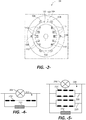
- FIG. 2 illustrates an exemplary cross sectional view of the superconducting generator 24 from FIG. 1 .
- the generator 24 includes an outer concentric component 104, which may be the stator, and an inner concentric component 106, which may be the rotor (e.g., in an internal rotor configuration)
- the outer component 104 may be a rotor of the generator 24, and the inner component 106 may be a stator of the generator 24 (e.g., in an external rotor configuration).
- a gap (or "air gap”) 105 is defined between the outer component 104 and inner component 106 and allows movement (e.g., rotation) therebetween.
- the generator 24 also includes a first set of one or more current carrying conductors ("coils") 108 attached to the outer component 104 and a second set of one or more current carrying conductors (“coils”) 110 attached to the inner component 106.
- these coils 108, 110 are in electromagnetic communication.
- the coils 108 may be armature coils, and coils 110 may be field coils of the generator 24. In other embodiments, the coils 108 may be field coils and the coils 110 may be armature coils of the generator 24.
- the field coils are connected to a source of excitation current (e.g., an "exciter"), wherein current flow therethrough produces a magnetic field across the field coil, and the armature coil is connected to the output of the generator 24 (e.g., via output terminals) to conduct an output current and electrical power output.
- a source of excitation current e.g., an "exciter”
- the armature coil is connected to the output of the generator 24 (e.g., via output terminals) to conduct an output current and electrical power output.
- the field coils e.g., coils 110
- the field coils are constructed of a superconducting material, such as niobium-titanium (NbTi), niobium-tin (Nb3Sn), or magnesium-boron (MgB2).
- the armature coils 108 are constructed from copper.
- the armature coils may be constructed of a superconducting material, such as NbTi, Nb3Sn, or MgB2.
- the superconducting material may also be a high temperature superconductor, such as YBCO or ReBCO.
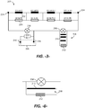
- FIG. 3 is a diagram of an embodiment of a quench protection system 200 in accordance with aspects of the present disclosure.
- the system 200 may be incorporated with a superconducting machine, such as an MRI machine or a superconducting generator (e.g. a superconducting wind turbine generator).
- a superconducting magnet includes a plurality of coils 202 depicted as SCG coil #1 through SCG coil #N connected in series. Each of these coils 202 has a corresponding switch heater 204 (labeled SW Htr #1 through SW Htr #N) electrically coupled therewith, for example in a parallel configuration therewith.
- Circuit includes leads 218 are provided for connection with a main power supply 226, wherein the leads 218 may be fixed or retractable. When connected to the main power supply 226, the superconductive coils 202 are supplied with a current via ends 224 of the series-arranged coils 202.
- a superconductive main switch 216 is configured in the system 200 in parallel with the coils 202.
- this switch 206 may be, for example, a ramping-switch with a superconductive wire portion and a heater portion impregnated in an epoxy. By controlling the heater portion, the wire portion can be switched between a resistive state and a superconductive state.
- This type of switch 206 is typically used to transfer the superconducting coils between a superconducting persistent operating mode and a non-persistent superconducting mode. Generally, the switch 206 is used to "ramp-up" the coils 202 to the persistent mode and to purposefully “ramp-down" the coils from the persistent mode.
- the system 200 includes a superconductive quench protection switch (QPS) 206 configured in series with the coils 202 and main switch 216.
- This QPS switch 206 may be the same type of switch as the main switch 216 discussed above.
- the main switch 216 needs a relatively long length of superconductor to provide a few ohms of resistance when it is resistive so that the joule heating on the main switch during ramp is manageable (not too high).
- the QPS switch 206 is generally similar in size or smaller in size as the main switch 216 with similar superconducting characteristics.
- the QPS 206 is also superconductive, and thus closed.
- Each of the switch heaters 204 are in thermal contact with the QPS 206, for example by being glued or otherwise fixed directly onto the surface of the QPS 206 .
- a heater network 208 is configured in parallel with the QPS 206 and is in thermal contact with each of the coils 202. With this unique configuration, a quench of any one of the coils 202 also triggers a quench of the QPS 206. The resulting voltage induced across the QPS 206 triggers the heater network 208 (causing current flow through individual heaters 210 in the network 208). This activation of the heater network 208 thus results in the subsequent, rapid quenching of all of the remaining coils 202.
- An additional particular advantage of the system 200 is that, due to placement of the QPS 206 in series with the coils 202 and main switch 216, quench protection is provided during ramp-up to persistent mode, as well as during persistent mode of operation.
- the heater network 208 may have various configurations of individual heaters 210, wherein each coil 202 is in thermal contact with at least one of the heaters 210.
- the N heaters 210 are configured in parallel within the heater network 208, wherein there is an individual heater 210 associated with each coil 202.
- the heater network 208 includes N heaters 210 connected in series, wherein there is an individual heater 210 associated with each coil 202.
- the heater network 208 may include heaters 210 configured in parallel and series.
- a first branch 220 in the heater network 208 includes a plurality of heaters 210 in series within separate lines, with the lines in parallel.
- the first branch 220 is in parallel with a similarly configured second branch 222.
- Fig. 6 depicts an embodiment of the heater network 208 that has a single heater 210, wherein each of the coils 202 is in thermal contact with the single heater 210.
- a voltage clamp device such as a diode configuration or shunt resistor, may be arranged across the heater network to limit the voltage applied across the heaters.
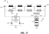
- FIG. 7 depicts an embodiment of the quench protection system 200 with the addition of a shielding coil 214 that shields the QPS 206 from the high field strength (e.g. to less than about 0.5T).
- the shielding coil 214 is self-shorted (not connected into the main current power supply circuit).
- Each of the superconducting field coils 202 has a shielding coil heater (not illustrated) electrically coupled therewith and in thermal communication with the shielding coil 214.
- the shielding coil 214 quenches similar to the QPS switch 206. Once any one of the coils 202 quenches, the QPS 206 and the shielding coil 214 will quench. When the coil 214 quenches, the QPS 206 will be exposed to the high field strength and quench spontaneously, which results in an accelerated triggering of the heater network 208 and subsequently quenching of the remaining coils 202.
- the embodiments described herein provide a quench protection system 200 that is relatively simple, reliable, and cost-efficient.
- the present system can be implemented with about a 2xN heater matrix (e.g., Fig. 6 ) or 3xN heater matrix (e.g., Fig. 7 ), a QPS, and a voltage clamping device if needed.
- the quench protection system provides protection during ramp-up as well as in persistent mode, as discussed above.
Landscapes
- Engineering & Computer Science (AREA)
- Power Engineering (AREA)
- Physics & Mathematics (AREA)
- Microelectronics & Electronic Packaging (AREA)
- Electromagnetism (AREA)
- Condensed Matter Physics & Semiconductors (AREA)
- General Physics & Mathematics (AREA)
- Superconductive Dynamoelectric Machines (AREA)
- Life Sciences & Earth Sciences (AREA)
- Sustainable Development (AREA)
- Sustainable Energy (AREA)
- Containers, Films, And Cooling For Superconductive Devices (AREA)
Abstract
Description
- The present disclosure relates generally to superconducting machines, such as superconducting wind turbine generators, and more particularly to quench protection systems and methods for such machines.
- Generally, superconducting generators are made by constructing the generator field coils (which typically carry a substantially direct current) of a superconducting material ("superconductor") instead of the usual copper material. Superconductors are typically lighter in weight and smaller in size (e.g., relative to current carrying capacity) than traditional conductors such as copper, and are also more efficient at conducting current (particularly at lower frequencies). Thus, the use of superconductors in power applications, such as wind turbine generators, provides benefits such as more efficient performance, lower generator weight, non-gearbox direct drive operation, and lower manufacturing and installation costs. Such benefits are particularly for offshore wind turbine applications.
- Protection circuits are configured with the superconducting generators to protect the superconducting magnet from damage that could otherwise occur during a quench. A quench occurs when a superconductor reverts to a resistive state as the result of localized heating in one part of the superconductor. When this part ceases to be superconductive, and enters a resistive state, any current flowing through the resistive part will cause local (Joule) heating. This, in turn, causes the adjacent parts of the superconductor to quench, resulting in a larger resistive volume, in turn causing further heating. Thus, in a rapid cascading fashion, the superconductor enters a resistive state, with a potentially very large current still flowing.
- Prior to the quench, the coils retain a large amount of stored energy, wherein after the quench, this energy will be dissipated in the resistive volume of the conductor. If the quench process is not adequately managed and the energy is dissipated in only confined areas (such as the initial quench site), such areas experience rapid and large temperature spikes, which can damage the coil areas at or near the location of the initial quench.
- A well-known quench protection methodology is to spread the quench process to essentially the entire mass of the superconductor to avoid the localized heating and dissipate the stored energy over as much of the available superconductor as possible. With certain types of superconducting machines, such as MRI machines, this quench protection is achieved by deliberately initiating a quench on the remaining superconductor coils after the initial quench by applying a current to one or more heaters that are in thermal contact with each coil. For a group of the coils, the heaters are configured in series, with the series arrangement in parallel with the coils. Thus, when one of the coils quenches, a rapid voltage rise develops across that coil and also across the series-connected heaters. Thus, a current will then flow through the series-connected heaters. The temperature rise caused by the heaters will then initiate a quench in the coils attached to the heaters. Thus, by initiating quenches in all of the coils, the energy is dissipated relatively evenly across all of the coils.
- The quench protection methodology discussed above is typically implemented by a cross-linked heater matrix, wherein for a magnet with N coils, a cross-linked N*N heater matrix is utilized. However, for a large superconducting generator, such as a direct-drive superconducting wind turbine generator having a relatively large number of poles (e.g. in excess of 30 poles, wherein each pole corresponds to a superconducting field coil), it would be very costly to implement an N*N heater matrix for quench protection.
- Accordingly, the industry is in need of an improved quench protection system and method that reduces the complexity and cost of conventional heater matrixes for larger superconducting generators, such as direct drive wind turbine generators.
- Aspects and advantages of the invention will be set forth in part in the following description, or may be obvious from the description, or may be learned through practice of the invention.
- In accordance with aspects of the present disclosure, a quench protection system is provided for a superconducting machine having a plurality of superconducting coils arranged in series. At least one switch heater (e.g. a resistor or restive network) may be electrically coupled across each of the superconducting coils. A quench protection switch is provided in series with the superconducting coils, wherein each of the switch heaters is in thermal contact with the quench protection switch. A heater network may be configured in parallel with the quench protection switch and may also be in thermal contact with each of the superconducting coils. With this unique configuration, a quench of any one of the superconducting coils activates the switch heater coupled therewith, and the activated switch heater triggers a quench of the quench protection switch. This quench of the quench protection switch then activates the heater network to trigger a quench of all remaining superconducting coils.
- The heater network may have various configurations. For example, in one embodiment, the heater network includes a plurality of heaters connected in parallel, with each superconducting coil in thermal contact with at least one of the heaters.
- In another embodiment, the heater network may include a plurality of heaters connected in series, with each superconducting coil in thermal contact with at least one of the heaters.
- In still another embodiment, the heater network may include a plurality of heaters connected in parallel and a plurality of heaters connected in series, with each superconducting coil in thermal contact with at least one of the heaters.
- In yet another embodiment, the heater network may include a single heater, with each superconducting coil in thermal contact with the single heater.
- It may be desired to include a voltage clamp device across the heater network to limit the voltage applied across the heaters.
- It may also be desired to include a shielding coil applied to the quench protection switch to accelerate quenching of the heater network.
- The present disclosure also encompasses a superconducting generator that includes a plurality of superconducting field coils and a quench protection system as discussed above. The superconducting generator may be configured, for example, as a superconducting wind turbine generator.
- The present invention encompasses a wind turbine power generating system that includes a tower; a hub, and a plurality of blades connected to the hub; a rotor connected to the hub; and a superconducting generator coupled to the rotor. The superconducting generator may be configured in accordance with any combination of the embodiments of the quench protection system and generator discussed above.
- The present invention also encompasses various methodologies for operating a superconducting generator, in particular a superconducting wind turbine generator, in accordance with the aspects discussed above.
- These and other features, aspects and advantages of the present invention will become better understood with reference to the following description and appended claims. The accompanying drawings, which are incorporated in and constitute a part of this specification, illustrate embodiments of the invention and, together with the description, serve to explain the principles of the invention.
- A full and enabling disclosure of the present invention, including the best mode thereof, directed to one of ordinary skill in the art, is set forth in the specification, which makes reference to the appended figures, in which:
-
FIG. 1 illustrates a perspective view of an embodiment of a wind turbine with a superconducting generator according to the present disclosure; -
FIG. 2 is a cross-sectional view of a superconducting generator; -
FIG. 3 is a diagram view of a quench protection system for a superconducting machine in accordance with aspects of the invention; -
FIG. 4 is a diagram view of an embodiment of a heater network for use in the quench protection system ofFIG. 3 ; -
FIG. 5 is a diagram view of an alternate embodiment of a heater network; -
FIG. 6 is a diagram view of another embodiment of a heater network; and -
FIG. 7 is a diagram view of an alternate embodiment of a quench protection system. - Reference now will be made in detail to embodiments of the invention, one or more examples of which are illustrated in the drawings. Each example is provided by way of explanation of the invention, not limitation of the invention. In fact, it will be apparent to those skilled in the art that various modifications and variations can be made in the present invention without departing from the scope or spirit of the invention. For instance, features illustrated or described as part of one embodiment can be used with another embodiment to yield a still further embodiment. Thus, it is intended that the present invention covers such modifications and variations as come within the scope of the appended claims and their equivalents.
- The present disclosure encompasses any manner of superconducting machine, and is not limited to superconducting generators. For sake of explanation, the present quench protection system is described herein with reference to a superconducting generator in general, and more particularly to a wind turbine superconducting generator.
- Referring now to the drawings,
FIG. 1 illustrates a perspective view of one embodiment of a wind turbinepower generating system 10. As shown, thewind turbine 10 generally includes atower 12 extending from asupport surface 14, anacelle 16 mounted on thetower 12, and arotor 18 coupled to thenacelle 16. Therotor 18 includes arotatable hub 20 and at least one rotor blade 22 (three are shown) coupled to and extending outwardly from thehub 20. Eachrotor blade 22 may be spaced about thehub 20 to facilitate rotating therotor 18 to enable kinetic energy to be transferred from the wind into usable mechanical energy, and subsequently, electrical energy. For this purpose, therotor 18 is coupled to agenerator 24 via ashaft 26. For purposes of the present disclosure, thegenerator 24 is a direct drive superconducting generator. - The present invention encompasses a wind turbine
power generating system 10, as described above, wherein thegenerator 24 is configured as a superconducting generator with a quench protection system as set forth below. - The present invention also encompasses various methodologies of operating a superconducting generator, in particular a wind turbine superconducting generator, with a quench protection system in accordance with method aspects set forth below.
-
FIG. 2 illustrates an exemplary cross sectional view of thesuperconducting generator 24 fromFIG. 1 . As depicted, thegenerator 24 includes an outerconcentric component 104, which may be the stator, and an innerconcentric component 106, which may be the rotor (e.g., in an internal rotor configuration) However, in other embodiments, theouter component 104 may be a rotor of thegenerator 24, and theinner component 106 may be a stator of the generator 24 (e.g., in an external rotor configuration). A gap (or "air gap") 105 is defined between theouter component 104 andinner component 106 and allows movement (e.g., rotation) therebetween. - The
generator 24 also includes a first set of one or more current carrying conductors ("coils") 108 attached to theouter component 104 and a second set of one or more current carrying conductors ("coils") 110 attached to theinner component 106. During operation of thegenerator 24, thesecoils coils 108 may be armature coils, and coils 110 may be field coils of thegenerator 24. In other embodiments, thecoils 108 may be field coils and thecoils 110 may be armature coils of thegenerator 24. The field coils are connected to a source of excitation current (e.g., an "exciter"), wherein current flow therethrough produces a magnetic field across the field coil, and the armature coil is connected to the output of the generator 24 (e.g., via output terminals) to conduct an output current and electrical power output. Althoughseveral coils less coils outer component 106 andinner component 108 in various embodiments, e.g., to configure the number of poles of thegenerator 24 and, thereby, the generating frequency and/or other operating characteristics of thegenerator 24. - The field coils, e.g., coils 110, are constructed of a superconducting material, such as niobium-titanium (NbTi), niobium-tin (Nb3Sn), or magnesium-boron (MgB2). Typically, the armature coils 108 are constructed from copper. However, in certain embodiments, the armature coils may be constructed of a superconducting material, such as NbTi, Nb3Sn, or MgB2. In certain embodiments, the superconducting material may also be a high temperature superconductor, such as YBCO or ReBCO.
-
FIG. 3 is a diagram of an embodiment of a quenchprotection system 200 in accordance with aspects of the present disclosure. Thesystem 200 may be incorporated with a superconducting machine, such as an MRI machine or a superconducting generator (e.g. a superconducting wind turbine generator). A superconducting magnet includes a plurality ofcoils 202 depicted asSCG coil # 1 through SCG coil #N connected in series. Each of thesecoils 202 has a corresponding switch heater 204 (labeledSW Htr # 1 through SW Htr #N) electrically coupled therewith, for example in a parallel configuration therewith. - Circuit includes leads 218 are provided for connection with a
main power supply 226, wherein theleads 218 may be fixed or retractable. When connected to themain power supply 226, thesuperconductive coils 202 are supplied with a current via ends 224 of the series-arrangedcoils 202. - A superconductive
main switch 216 is configured in thesystem 200 in parallel with thecoils 202. As known in the art, thisswitch 206 may be, for example, a ramping-switch with a superconductive wire portion and a heater portion impregnated in an epoxy. By controlling the heater portion, the wire portion can be switched between a resistive state and a superconductive state. This type ofswitch 206 is typically used to transfer the superconducting coils between a superconducting persistent operating mode and a non-persistent superconducting mode. Generally, theswitch 206 is used to "ramp-up" thecoils 202 to the persistent mode and to purposefully "ramp-down" the coils from the persistent mode. When thesystem 200 is connected to a current source (power supply 226) via theleads 218, current flows through thecoils 202 and themain switch 216. When the magnet/coils 202 are ramped-up to the required current, themain switch 216 becomes superconductive and is closed. As the power supply connected to theleads 218 is ramped down, the current through themain switch 216 increases by essentially the same amount as the decrease in the external power supply current. Once the external power supply is ramped down completely, theleads 218 are disconnected from the external power supply. At this point, thesuperconductive coils 202 are in the persistent operating mode. - The
system 200 includes a superconductive quench protection switch (QPS) 206 configured in series with thecoils 202 andmain switch 216. ThisQPS switch 206 may be the same type of switch as themain switch 216 discussed above. Themain switch 216 needs a relatively long length of superconductor to provide a few ohms of resistance when it is resistive so that the joule heating on the main switch during ramp is manageable (not too high). TheQPS switch 206 is generally similar in size or smaller in size as themain switch 216 with similar superconducting characteristics. - In the persistent operating mode, the
QPS 206 is also superconductive, and thus closed. Each of theswitch heaters 204 are in thermal contact with theQPS 206, for example by being glued or otherwise fixed directly onto the surface of theQPS 206 . - When one of the
coils 202 quenches, a voltage rapidly develops across thatcoil 202, and so also across the associatedswitch heater 204 electrically coupled thereto, causing a current to flow through theswitch heater 204. Theswitch heater 204 is in thermal contact with theQPS 206 and will thus cause theQPS 206 to quench. - A
heater network 208 is configured in parallel with theQPS 206 and is in thermal contact with each of thecoils 202. With this unique configuration, a quench of any one of thecoils 202 also triggers a quench of theQPS 206. The resulting voltage induced across theQPS 206 triggers the heater network 208 (causing current flow throughindividual heaters 210 in the network 208). This activation of theheater network 208 thus results in the subsequent, rapid quenching of all of the remaining coils 202. - An additional particular advantage of the
system 200 is that, due to placement of theQPS 206 in series with thecoils 202 andmain switch 216, quench protection is provided during ramp-up to persistent mode, as well as during persistent mode of operation. - The
heater network 208 may have various configurations ofindividual heaters 210, wherein eachcoil 202 is in thermal contact with at least one of theheaters 210. For example, in the embodiment ofFIG. 3 , theN heaters 210 are configured in parallel within theheater network 208, wherein there is anindividual heater 210 associated with eachcoil 202. - In another embodiment depicted in
FIG. 4 , theheater network 208 includesN heaters 210 connected in series, wherein there is anindividual heater 210 associated with eachcoil 202. - In another embodiment, the
heater network 208 may includeheaters 210 configured in parallel and series. For example in the embodiment ofFIG. 5 , afirst branch 220 in theheater network 208 includes a plurality ofheaters 210 in series within separate lines, with the lines in parallel. Thefirst branch 220 is in parallel with a similarly configured second branch 222. -
Fig. 6 depicts an embodiment of theheater network 208 that has asingle heater 210, wherein each of thecoils 202 is in thermal contact with thesingle heater 210. - As depicted for example in the embodiment of the
system 200 inFIG. 3 , a voltage clamp device, such as a diode configuration or shunt resistor, may be arranged across the heater network to limit the voltage applied across the heaters. - It may be desired to locate the
QPS 206 in the high magnetic field (e.g., around 2-4T field region) relatively close to the superconducting field coils 202 in a generator to further enhance the quench propagation speed in all of thecoils 202. In this case,FIG. 7 depicts an embodiment of the quenchprotection system 200 with the addition of a shieldingcoil 214 that shields theQPS 206 from the high field strength (e.g. to less than about 0.5T). The shieldingcoil 214 is self-shorted (not connected into the main current power supply circuit). Each of the superconducting field coils 202 has a shielding coil heater (not illustrated) electrically coupled therewith and in thermal communication with the shieldingcoil 214. The shieldingcoil 214 quenches similar to theQPS switch 206. Once any one of thecoils 202 quenches, theQPS 206 and the shieldingcoil 214 will quench. When thecoil 214 quenches, theQPS 206 will be exposed to the high field strength and quench spontaneously, which results in an accelerated triggering of theheater network 208 and subsequently quenching of the remaining coils 202. - The embodiments described herein provide a quench
protection system 200 that is relatively simple, reliable, and cost-efficient. Instead of an (NxN) switch heater matrix as used in conventional quench protections systems, the present system can be implemented with about a 2xN heater matrix (e.g.,Fig. 6 ) or 3xN heater matrix (e.g.,Fig. 7 ), a QPS, and a voltage clamping device if needed. The quench protection system provides protection during ramp-up as well as in persistent mode, as discussed above. - Various aspects and embodiments of the present invention are defined by the following numbered clauses:
- 1. A quench protection system for a superconducting machine having a plurality of superconducting coils arranged in series, comprising:
- at least one switch heater electrically coupled across each of the superconducting coils;
- a quench protection switch configured in series with the superconducting coils, each of the switch heaters in thermal contact with the quench protection switch;
- a heater network configured in parallel with the quench protection switch, the heater network in thermal contact with each of the coils;
- such that a quench of any one of the superconducting coils activates the switch heater coupled therewith and the activated switch heater triggers a quench of the quench protection switch; and
- wherein the quench of the quench protection switch activates the heater network to trigger a quench of all remaining superconducting coils.
- 2. The quench protection system as in
clause 1, wherein the heater network comprises a plurality of heaters connected in parallel, with each superconducting coil in thermal contact with at least one of the heaters. - 3. The quench protection system as in any preceding clause, wherein the heater network comprises a plurality of heaters connected in series, with each superconducting coil in thermal contact with at least one of the heaters.
- 4. The quench protection system as in any preceding clause, wherein the heater network comprises a plurality of heaters connected in parallel and a plurality of heaters connected in series, with each superconducting coil in thermal contact with at least one of the heaters.
- 5. The quench protection system as in any preceding clause, wherein the heater network comprises a single heater, with each superconducting coil in thermal contact with the single heater.
- 6. The quench protection system as in any preceding clause, further comprising a voltage clamp device across the heater network.
- 7. The quench protection system as in any preceding clause, further comprising a shielding coil applied to the quench protection switch to accelerate quenching of the heater network.
- 8. A superconducting generator, comprising:
- a plurality of superconducting field coils arranged in series;
- a quench protection system, the quench protection system further comprising:
- at least one switch heater electrically coupled across each of the superconducting coils;
- a quench protection switch configured in series with the superconducting coils, each of the switch heaters in thermal contact with the quench protection switch;
- a heater network configured in parallel with the quench protection switch, the heater network in thermal contact with each of the coils;
- such that a quench of any one of the superconducting coils activates the switch heater coupled therewith and the activated switch heater triggers a quench of the quench protection switch; and
- wherein the quench of the quench protection switch activates the heater network to trigger a quench of all remaining superconducting coils.
- 9. The superconducting generator as in clause 8, wherein the heater network comprises a plurality of heaters connected in parallel, with each superconducting coil in thermal contact with at least one of the heaters.
- 10. The superconducting generator as in any one of clauses 8-9, wherein the heater network comprises a plurality of heaters connected in series, with each superconducting coil in thermal contact with at least one of the heaters.
- 11. The superconducting generator as in any one of clauses 8-10, wherein the heater network comprises a plurality of heaters connected in parallel and a plurality of heaters connected in series, with each superconducting coil in thermal contact with at least one of the heaters.
- 12. The superconducting generator as in any one of clauses 8-11, wherein the heater network comprises a single heater, with each superconducting coil in thermal contact with the single heater.
- 13. The superconducting generator as in any one of clauses 8-12, further comprising a voltage clamp device across the heater network.
- 14. The superconducting generator as in any one of clauses 8-13, further comprising a shielding coil applied to the quench protection switch to accelerate quenching of the heater network.
- 15. The superconducting generator as in any one of clauses 8-14, wherein the superconducting generator is a wind turbine generator.
- 16. A wind turbine power generating system, comprising a superconducting generator as in any one of clauses 8-14.
- This written description uses examples to disclose the invention, including the best mode, and also to enable any person skilled in the art to practice the invention, including making and using any devices or systems and performing any incorporated methods. The patentable scope of the invention is defined by the claims, and may include other examples that occur to those skilled in the art. Such other examples are intended to be within the scope of the claims if they include structural elements that do not differ from the literal language of the claims, or if they include equivalent structural elements with insubstantial differences from the literal languages of the claims.
Claims (12)
- A quench protection system for a superconducting machine having a plurality of superconducting coils arranged in series, comprising:at least one switch heater electrically coupled across each of the superconducting coils;a quench protection switch configured in series with the superconducting coils, each of the switch heaters in thermal contact with the quench protection switch;a heater network configured in parallel with the quench protection switch, the heater network in thermal contact with each of the coils;such that a quench of any one of the superconducting coils activates the switch heater coupled therewith and the activated switch heater triggers a quench of the quench protection switch; andwherein the quench of the quench protection switch activates the heater network to trigger a quench of all remaining superconducting coils.
- The quench protection system as in claim 1, wherein the heater network comprises one or both of (a) a plurality of heaters connected in parallel, with each superconducting coil in thermal contact with at least one of the heaters, and (b) a plurality of heaters connected in series, with each superconducting coil in thermal contact with at least one of the heaters.
- The quench protection system as in claim 1, wherein the heater network comprises a single heater, with each superconducting coil in thermal contact with the single heater.
- The quench protection system as in any one of claims 1-3, further comprising a voltage clamp device across the heater network.
- The quench protection system as in any one of claims 1-4, further comprising a shielding coil applied to the quench protection switch to accelerate quenching of the heater network.
- A superconducting generator, comprising:a plurality of superconducting field coils arranged in series;a quench protection system, the quench protection system further comprising:at least one switch heater electrically coupled across each of the field coils;a quench protection switch configured in series with the superconducting coils, each of the switch heaters in thermal contact with the quench protection switch;a heater network configured in parallel with the quench protection switch, the heater network in thermal contact with each of the coils;such that a quench of any one of the superconducting coils activates the switch heater coupled therewith and the activated switch heater triggers a quench of the quench protection switch; andwherein the quench of the quench protection switch activates the heater network to trigger a quench of all remaining superconducting coils.
- The superconducting generator as in claim 6, wherein the heater network comprises one or both of (a) a plurality of heaters connected in parallel, with each superconducting coil in thermal contact with at least one of the heaters, and (b) a plurality of heaters connected in series, with each superconducting coil in thermal contact with at least one of the heaters.
- The superconducting generator as in claim 6, wherein the heater network comprises a single heater, with each superconducting coil in thermal contact with the single heater.
- The superconducting generator as in any one of claims 6 through 8, further comprising a voltage clamp device across the heater network.
- The superconducting generator as in any one of claims 6 through 9, further comprising a shielding coil applied to the quench protection switch to accelerate quenching of the heater network.
- The superconducting generator as in any one of claims 6 through 10, wherein the superconducting generator is a wind turbine generator.
- A wind turbine power generating system, comprising:a tower;a hub, and a plurality of blades connected to the hub;a rotor connected to the hub; andthe superconducting generator according to any one of claims 6 through 11.
Applications Claiming Priority (1)
| Application Number | Priority Date | Filing Date | Title |
|---|---|---|---|
| US16/373,960 US11521771B2 (en) | 2019-04-03 | 2019-04-03 | System for quench protection of superconducting machines, such as a superconducting wind turbine generator |
Publications (3)
| Publication Number | Publication Date |
|---|---|
| EP3719948A1 true EP3719948A1 (en) | 2020-10-07 |
| EP3719948B1 EP3719948B1 (en) | 2026-02-18 |
| EP3719948B8 EP3719948B8 (en) | 2026-04-01 |
Family
ID=69846371
Family Applications (1)
| Application Number | Title | Priority Date | Filing Date |
|---|---|---|---|
| EP20164284.0A Active EP3719948B8 (en) | 2019-04-03 | 2020-03-19 | System for quench protection of superconducting machines, such as a superconducting wind turbine generator |
Country Status (3)
| Country | Link |
|---|---|
| US (1) | US11521771B2 (en) |
| EP (1) | EP3719948B8 (en) |
| CN (1) | CN111799953B (en) |
Families Citing this family (1)
| Publication number | Priority date | Publication date | Assignee | Title |
|---|---|---|---|---|
| CN121096765A (en) * | 2025-09-28 | 2025-12-09 | 奥泰医疗系统有限责任公司 | Magnet system shielding coil and quench protection combined design structure and method |
Citations (4)
| Publication number | Priority date | Publication date | Assignee | Title |
|---|---|---|---|---|
| US20120182012A1 (en) * | 2011-01-19 | 2012-07-19 | Yuri Lvovsky | Apparatus and method for protecting a magnetic resonance imaging magnet during quench |
| US8914086B2 (en) * | 2011-07-29 | 2014-12-16 | General Electric Company | Superconducting magnet system |
| US9240681B2 (en) * | 2012-12-27 | 2016-01-19 | General Electric Company | Superconducting coil system and methods of assembling the same |
| CN107221401A (en) * | 2016-03-22 | 2017-09-29 | 上海联影医疗科技有限公司 | A kind of superconducting magnet system and its quench guard method |
Family Cites Families (55)
| Publication number | Priority date | Publication date | Assignee | Title |
|---|---|---|---|---|
| US904607A (en) | 1908-03-16 | 1908-11-24 | Hjalmar Elmblad | Seal-lock. |
| JPH0529137A (en) * | 1991-07-25 | 1993-02-05 | Fuji Electric Co Ltd | Superconducting electromagnet |
| US5627709A (en) | 1995-08-11 | 1997-05-06 | General Electric Company | Electrical circuit for protecting a superconducting magnet during a quench |
| US5731939A (en) | 1996-09-04 | 1998-03-24 | General Electric Company | Quench-protecting electrical circuit for a superconducting magnet |
| JPH10336999A (en) | 1997-06-04 | 1998-12-18 | Mitsubishi Electric Corp | Superconducting magnet |
| JP3788702B2 (en) | 1999-03-03 | 2006-06-21 | 三菱電機株式会社 | Superconducting rotating electrical machine rotor |
| DE10222768B3 (en) | 2002-05-16 | 2004-01-22 | Siemens Ag | Quench |
| US7071579B2 (en) | 2002-06-07 | 2006-07-04 | Global Energyconcepts,Llc | Wind farm electrical system |
| WO2004025803A1 (en) | 2002-09-13 | 2004-03-25 | Abb Ab | Wind power fed network |
| JP2004172485A (en) | 2002-11-21 | 2004-06-17 | Nagoya Industrial Science Research Inst | Quenching detecting method and equipment of superconductive coil, |
| US7095597B1 (en) | 2003-04-30 | 2006-08-22 | Clipper Windpower Technology, Inc. | Distributed static var compensation (DSVC) system for wind and water turbine applications |
| US6924565B2 (en) | 2003-08-18 | 2005-08-02 | General Electric Company | Continuous reactive power support for wind turbine generators |
| US7119452B2 (en) | 2003-09-03 | 2006-10-10 | General Electric Company | Voltage control for wind generators |
| US7013203B2 (en) | 2003-10-22 | 2006-03-14 | General Electric Company | Wind turbine system control |
| US7053509B2 (en) | 2004-03-30 | 2006-05-30 | General Electric Company | Quench monitoring and control system and method of operating same |
| US7342757B2 (en) | 2004-06-28 | 2008-03-11 | General Electric Company | System and method for quench protection of a superconductor |
| US6900714B1 (en) | 2004-06-30 | 2005-05-31 | General Electric Company | System and method for quench and over-current protection of superconductor |
| JP4319602B2 (en) | 2004-08-31 | 2009-08-26 | 株式会社日立製作所 | Superconducting magnet device with quench protection circuit |
| GB2422958B (en) | 2005-02-04 | 2008-07-09 | Siemens Magnet Technology Ltd | Quench protection circuit for a superconducting magnet |
| US7630179B2 (en) | 2005-09-22 | 2009-12-08 | Reliance Electric Technologies, Llc | Protective link for superconducting coil |
| US7567160B2 (en) | 2006-02-15 | 2009-07-28 | American Superconductor Corporation | Supplementary transformer cooling in a reactive power compensation system |
| US20090103217A1 (en) | 2007-10-17 | 2009-04-23 | General Electric Company | System and apparatus for limiting current in a superconducting coil |
| GB2456308B (en) * | 2008-01-09 | 2011-01-26 | Gen Electric | Method and apparatus for actively controlling quench protection of a superconducting magnet |
| US20090224550A1 (en) | 2008-03-06 | 2009-09-10 | General Electric Company | Systems involving superconducting direct drive generators for wind power applications |
| US7724483B2 (en) | 2008-03-19 | 2010-05-25 | General Electric Company | Systems and methods involving protection of superconducting generators for power applications |
| WO2011012733A1 (en) | 2009-07-27 | 2011-02-03 | Gamesa Innovation & Technology, S.L. | System for reactive power compensation in electricity system |
| US8780510B2 (en) | 2009-09-23 | 2014-07-15 | General Electric Company | Passive quench protection circuit for superconducting magnets |
| US7923862B2 (en) | 2009-10-06 | 2011-04-12 | General Electric Company | Reactive power regulation and voltage support for renewable energy plants |
| US9236742B2 (en) | 2010-02-25 | 2016-01-12 | Vestas Wind Systems A/S | Method and control arrangement for controlling a reactive power source |
| AU2011260701B2 (en) | 2010-06-03 | 2015-08-20 | Vestas Wind Systems A/S | Method and control arrangement for controlling central capacitors in wind power plants |
| US8664800B2 (en) | 2010-08-31 | 2014-03-04 | General Electric Company | System and method for distribution of inverter VAR support |
| CN102412047B (en) | 2010-09-21 | 2014-07-30 | 通用电气公司 | Superconducting magnet and superconducting magnet system |
| EP2503146B1 (en) | 2011-03-21 | 2013-12-18 | Siemens Aktiengesellschaft | Method and arrangement for controlling an operation of an electric energy production facility during a disconnection to a utility grid. |
| GB201107888D0 (en) | 2011-05-12 | 2011-06-22 | Rolls Royce Plc | Superconducting electrical machine |
| US9368971B2 (en) | 2011-06-23 | 2016-06-14 | Inventus Holdings, Llc | Multiple renewables site electrical generation and reactive power control |
| US8482369B2 (en) * | 2011-10-31 | 2013-07-09 | General Electric Company | Single switch dump resistor ladder network for magnet quench protection |
| KR101460341B1 (en) | 2011-12-01 | 2014-11-21 | 두산중공업 주식회사 | A Protecting Structure and Method of a Field Coil for Superconducting Rotating Machines |
| CN104641529B (en) | 2012-09-17 | 2018-09-18 | 维斯塔斯风力系统集团公司 | Method for determining the individual set point in generating equipment controller and generating equipment controller |
| IN2015DN02395A (en) | 2012-09-17 | 2015-09-04 | Vestas Wind Sys As | |
| CN102882229B (en) | 2012-09-21 | 2015-06-17 | 北京金风科创风电设备有限公司 | Automatic control system for dynamic voltage of wind power plant |
| CN103700461B (en) * | 2012-09-27 | 2016-12-21 | 通用电气公司 | superconducting magnet system |
| EP2741392A3 (en) | 2012-12-04 | 2016-12-14 | ABB Research Ltd. | Systems and methods for utilizing an active compensator to augment a diode rectifier |
| US9680307B2 (en) | 2012-12-21 | 2017-06-13 | General Electric Company | System and method for voltage regulation of a renewable energy plant |
| EP2957012B1 (en) | 2013-02-15 | 2017-05-03 | Vestas Wind Systems A/S | A method of operating a wind turbine plant |
| KR101486753B1 (en) | 2013-06-20 | 2015-02-04 | 두산엔진주식회사 | System for super conducting electric power generation |
| KR101497809B1 (en) | 2013-06-24 | 2015-03-02 | 두산엔진주식회사 | System for super conducting electric power homopolar generator |
| JP6227917B2 (en) | 2013-07-19 | 2017-11-08 | 株式会社前川製作所 | Active quench detection method for superconducting magnets |
| US9638774B2 (en) | 2013-08-05 | 2017-05-02 | Shahin Pourrahimi | Discharge controlled superconducting magnet |
| JP6310221B2 (en) | 2013-09-30 | 2018-04-11 | 株式会社前川製作所 | Passive quench detection method for superconducting magnets |
| EP3075054B1 (en) | 2013-11-28 | 2019-01-09 | Vestas Wind Systems A/S | Reconfiguration of the reactive power loop of a wind power plant |
| US9419439B2 (en) | 2014-01-14 | 2016-08-16 | Siemens Aktiengesellschaft | Reconnecting a wind power plant to a utility grid |
| CN105513743B (en) * | 2014-10-17 | 2019-01-01 | 通用电气公司 | Superconducting magnet system and its quenching protection device |
| US9874618B2 (en) | 2014-12-24 | 2018-01-23 | General Electric Company | Control system and method for a superconducting magnet |
| US9831810B2 (en) | 2015-03-10 | 2017-11-28 | General Electric Company | System and method for improved reactive power speed-of-response for a wind farm |
| GB2540623A (en) | 2015-07-24 | 2017-01-25 | Tesla Eng Ltd | Superconducting winding arrangements |
-
2019
- 2019-04-03 US US16/373,960 patent/US11521771B2/en active Active
-
2020
- 2020-03-19 EP EP20164284.0A patent/EP3719948B8/en active Active
- 2020-04-03 CN CN202010259194.2A patent/CN111799953B/en active Active
Patent Citations (4)
| Publication number | Priority date | Publication date | Assignee | Title |
|---|---|---|---|---|
| US20120182012A1 (en) * | 2011-01-19 | 2012-07-19 | Yuri Lvovsky | Apparatus and method for protecting a magnetic resonance imaging magnet during quench |
| US8914086B2 (en) * | 2011-07-29 | 2014-12-16 | General Electric Company | Superconducting magnet system |
| US9240681B2 (en) * | 2012-12-27 | 2016-01-19 | General Electric Company | Superconducting coil system and methods of assembling the same |
| CN107221401A (en) * | 2016-03-22 | 2017-09-29 | 上海联影医疗科技有限公司 | A kind of superconducting magnet system and its quench guard method |
Also Published As
| Publication number | Publication date |
|---|---|
| CN111799953B (en) | 2025-08-22 |
| EP3719948B8 (en) | 2026-04-01 |
| EP3719948B1 (en) | 2026-02-18 |
| US11521771B2 (en) | 2022-12-06 |
| US20200321152A1 (en) | 2020-10-08 |
| CN111799953A (en) | 2020-10-20 |
Similar Documents
| Publication | Publication Date | Title |
|---|---|---|
| Hamilton et al. | Design and performance of a “squirrel-cage” dynamo-type HTS flux pump | |
| EP3084907B1 (en) | Variable impedance device for a wind turbine | |
| US9240681B2 (en) | Superconducting coil system and methods of assembling the same | |
| EP2108833A2 (en) | Systems involving superconducting direct drive generators for wind power applications | |
| GB1586031A (en) | Stored field superconducting electrical machine and method for providing such field in the machine and for operating the machine | |
| US6507259B2 (en) | Actively shielded superconducting magnet with protection means | |
| Ravaioli et al. | Advanced quench protection for the Nb 3 Sn quadrupoles for the high luminosity LHC | |
| US6809910B1 (en) | Method and apparatus to trigger superconductors in current limiting devices | |
| CN111794913B (en) | System and method for automatic ramping and energy release of superconducting wind turbine generators | |
| EP3719948B1 (en) | System for quench protection of superconducting machines, such as a superconducting wind turbine generator | |
| Bong et al. | No-insulation REBCO field winding assembly for CRUISE motor | |
| Ishmael et al. | Flux pump excited double-helix rotor for use in synchronous machines | |
| Wu et al. | Design and test of quench protection for superconducting generator field coils | |
| Schreiner et al. | Investigation of a six-pole stator system using no-insulation 2nd generation HTS coils for a 10 kW generator demonstrator | |
| JP7187658B2 (en) | Superconducting electromagnetic coil system | |
| US20140103774A1 (en) | Wound-field synchronous machine including rotor damper-sleeve | |
| Magnusson et al. | Design aspects on winding of an MgB2 superconducting generator coil | |
| Bailey et al. | Short circuit tests on a coreless HTS synchronous generator | |
| IL257564B2 (en) | Hybrid superconducting magnetic device | |
| KR101497809B1 (en) | System for super conducting electric power homopolar generator | |
| Wang et al. | Design and fabrication of a cross-warm-bore split-gap superconducting magnet system | |
| KR101480765B1 (en) | Straight section pressure apparatus of race track coil for superconducting rotating machine | |
| EP4085502B1 (en) | An electrical generator and method of operating the same | |
| Hayashi et al. | Fabrication and test of a 4 kJ Bi-2223 pulse coil for SMES | |
| US11937519B1 (en) | Permanent magnets using high temperature superconductor tapes and methods of charging same |
Legal Events
| Date | Code | Title | Description |
|---|---|---|---|
| PUAI | Public reference made under article 153(3) epc to a published international application that has entered the european phase |
Free format text: ORIGINAL CODE: 0009012 |
|
| STAA | Information on the status of an ep patent application or granted ep patent |
Free format text: STATUS: THE APPLICATION HAS BEEN PUBLISHED |
|
| AK | Designated contracting states |
Kind code of ref document: A1 Designated state(s): AL AT BE BG CH CY CZ DE DK EE ES FI FR GB GR HR HU IE IS IT LI LT LU LV MC MK MT NL NO PL PT RO RS SE SI SK SM TR |
|
| AX | Request for extension of the european patent |
Extension state: BA ME |
|
| STAA | Information on the status of an ep patent application or granted ep patent |
Free format text: STATUS: REQUEST FOR EXAMINATION WAS MADE |
|
| 17P | Request for examination filed |
Effective date: 20210407 |
|
| RBV | Designated contracting states (corrected) |
Designated state(s): AL AT BE BG CH CY CZ DE DK EE ES FI FR GB GR HR HU IE IS IT LI LT LU LV MC MK MT NL NO PL PT RO RS SE SI SK SM TR |
|
| STAA | Information on the status of an ep patent application or granted ep patent |
Free format text: STATUS: EXAMINATION IS IN PROGRESS |
|
| 17Q | First examination report despatched |
Effective date: 20220518 |
|
| P01 | Opt-out of the competence of the unified patent court (upc) registered |
Effective date: 20230529 |
|
| RAP1 | Party data changed (applicant data changed or rights of an application transferred) |
Owner name: GENERAL ELECTRIC RENOVABLES ESPANA, S.L. |
|
| GRAP | Despatch of communication of intention to grant a patent |
Free format text: ORIGINAL CODE: EPIDOSNIGR1 |
|
| STAA | Information on the status of an ep patent application or granted ep patent |
Free format text: STATUS: GRANT OF PATENT IS INTENDED |
|
| INTG | Intention to grant announced |
Effective date: 20250321 |
|
| GRAJ | Information related to disapproval of communication of intention to grant by the applicant or resumption of examination proceedings by the epo deleted |
Free format text: ORIGINAL CODE: EPIDOSDIGR1 |
|
| STAA | Information on the status of an ep patent application or granted ep patent |
Free format text: STATUS: EXAMINATION IS IN PROGRESS |
|
| INTC | Intention to grant announced (deleted) | ||
| GRAP | Despatch of communication of intention to grant a patent |
Free format text: ORIGINAL CODE: EPIDOSNIGR1 |
|
| STAA | Information on the status of an ep patent application or granted ep patent |
Free format text: STATUS: GRANT OF PATENT IS INTENDED |
|
| INTG | Intention to grant announced |
Effective date: 20250910 |
|
| GRAS | Grant fee paid |
Free format text: ORIGINAL CODE: EPIDOSNIGR3 |
|
| GRAA | (expected) grant |
Free format text: ORIGINAL CODE: 0009210 |
|
| STAA | Information on the status of an ep patent application or granted ep patent |
Free format text: STATUS: THE PATENT HAS BEEN GRANTED |
|
| AK | Designated contracting states |
Kind code of ref document: B1 Designated state(s): AL AT BE BG CH CY CZ DE DK EE ES FI FR GB GR HR HU IE IS IT LI LT LU LV MC MK MT NL NO PL PT RO RS SE SI SK SM TR |
|
| REG | Reference to a national code |
Ref country code: CH Ref legal event code: F10 Free format text: ST27 STATUS EVENT CODE: U-0-0-F10-F00 (AS PROVIDED BY THE NATIONAL OFFICE) Effective date: 20260218 Ref country code: CH Ref legal event code: W10 Free format text: ST27 STATUS EVENT CODE: U-0-0-W10-W00 (AS PROVIDED BY THE NATIONAL OFFICE) Effective date: 20260218 Ref country code: GB Ref legal event code: FG4D |
|
| REG | Reference to a national code |
Ref country code: DE Ref legal event code: R081 Ref document number: 602020066952 Country of ref document: DE Owner name: GE VERNOVA RENOVABLES ESPANA, S.L., ES Free format text: FORMER OWNER: GENERAL ELECTRIC RENOVABLES ESPANA S.L., BARCELONA, ES |
|
| REG | Reference to a national code |
Ref country code: CH Ref legal event code: Q17 Free format text: ST27 STATUS EVENT CODE: U-0-0-Q10-Q17 (AS PROVIDED BY THE NATIONAL OFFICE) Effective date: 20260304 |
|
| REG | Reference to a national code |
Ref country code: DE Ref legal event code: R096 Ref document number: 602020066952 Country of ref document: DE |
|
| REG | Reference to a national code |
Ref country code: IE Ref legal event code: FG4D |
|
| RAP4 | Party data changed (patent owner data changed or rights of a patent transferred) |
Owner name: GE VERNOVA RENOVABLES ESPANA, S.L. |
|
| REG | Reference to a national code |
Ref country code: CH Ref legal event code: W10 Free format text: ST27 STATUS EVENT CODE: U-0-0-W10-W00 (AS PROVIDED BY THE NATIONAL OFFICE) Effective date: 20260325 |
|
| REG | Reference to a national code |
Ref country code: DE Ref legal event code: R081 Ref document number: 602020066952 Country of ref document: DE Owner name: GE VERNOVA RENOVABLES ESPANA, S.L., ES Free format text: FORMER OWNER: GE VERNOVA RENOVABLES ESPANA, S.L., BARCELONA, ES |
|
| PGFP | Annual fee paid to national office [announced via postgrant information from national office to epo] |
Ref country code: FR Payment date: 20260323 Year of fee payment: 7 |
|
| RAP4 | Party data changed (patent owner data changed or rights of a patent transferred) |
Owner name: GE VERNOVA RENOVABLES ESPANA, S.L. |
|
| REG | Reference to a national code |
Ref country code: NL Ref legal event code: MP Effective date: 20260218 |
|
| PG25 | Lapsed in a contracting state [announced via postgrant information from national office to epo] |
Ref country code: RS Free format text: LAPSE BECAUSE OF FAILURE TO SUBMIT A TRANSLATION OF THE DESCRIPTION OR TO PAY THE FEE WITHIN THE PRESCRIBED TIME-LIMIT Effective date: 20260518 |
|
| PG25 | Lapsed in a contracting state [announced via postgrant information from national office to epo] |
Ref country code: ES Free format text: LAPSE BECAUSE OF FAILURE TO SUBMIT A TRANSLATION OF THE DESCRIPTION OR TO PAY THE FEE WITHIN THE PRESCRIBED TIME-LIMIT Effective date: 20260218 |
|
| PG25 | Lapsed in a contracting state [announced via postgrant information from national office to epo] |
Ref country code: PL Free format text: LAPSE BECAUSE OF FAILURE TO SUBMIT A TRANSLATION OF THE DESCRIPTION OR TO PAY THE FEE WITHIN THE PRESCRIBED TIME-LIMIT Effective date: 20260218 |
|
| PG25 | Lapsed in a contracting state [announced via postgrant information from national office to epo] |
Ref country code: GR Free format text: LAPSE BECAUSE OF FAILURE TO SUBMIT A TRANSLATION OF THE DESCRIPTION OR TO PAY THE FEE WITHIN THE PRESCRIBED TIME-LIMIT Effective date: 20260519 |
|
| REG | Reference to a national code |
Ref country code: LT Ref legal event code: MG9D |
|
| PG25 | Lapsed in a contracting state [announced via postgrant information from national office to epo] |
Ref country code: LT Free format text: LAPSE BECAUSE OF FAILURE TO SUBMIT A TRANSLATION OF THE DESCRIPTION OR TO PAY THE FEE WITHIN THE PRESCRIBED TIME-LIMIT Effective date: 20260218 |
|
| PGFP | Annual fee paid to national office [announced via postgrant information from national office to epo] |
Ref country code: DE Payment date: 20260331 Year of fee payment: 7 |
|
| PG25 | Lapsed in a contracting state [announced via postgrant information from national office to epo] |
Ref country code: NO Free format text: LAPSE BECAUSE OF FAILURE TO SUBMIT A TRANSLATION OF THE DESCRIPTION OR TO PAY THE FEE WITHIN THE PRESCRIBED TIME-LIMIT Effective date: 20260518 |
|
| PG25 | Lapsed in a contracting state [announced via postgrant information from national office to epo] |
Ref country code: FI Free format text: LAPSE BECAUSE OF FAILURE TO SUBMIT A TRANSLATION OF THE DESCRIPTION OR TO PAY THE FEE WITHIN THE PRESCRIBED TIME-LIMIT Effective date: 20260218 Ref country code: AT Free format text: LAPSE BECAUSE OF FAILURE TO SUBMIT A TRANSLATION OF THE DESCRIPTION OR TO PAY THE FEE WITHIN THE PRESCRIBED TIME-LIMIT Effective date: 20260218 Ref country code: SE Free format text: LAPSE BECAUSE OF FAILURE TO SUBMIT A TRANSLATION OF THE DESCRIPTION OR TO PAY THE FEE WITHIN THE PRESCRIBED TIME-LIMIT Effective date: 20260218 |
|
| REG | Reference to a national code |
Ref country code: AT Ref legal event code: MK05 Ref document number: 1889272 Country of ref document: AT Kind code of ref document: T Effective date: 20260218 |
|
| PG25 | Lapsed in a contracting state [announced via postgrant information from national office to epo] |
Ref country code: HR Free format text: LAPSE BECAUSE OF FAILURE TO SUBMIT A TRANSLATION OF THE DESCRIPTION OR TO PAY THE FEE WITHIN THE PRESCRIBED TIME-LIMIT Effective date: 20260218 |
|
| PG25 | Lapsed in a contracting state [announced via postgrant information from national office to epo] |
Ref country code: IS Free format text: LAPSE BECAUSE OF FAILURE TO SUBMIT A TRANSLATION OF THE DESCRIPTION OR TO PAY THE FEE WITHIN THE PRESCRIBED TIME-LIMIT Effective date: 20260618 Ref country code: PT Free format text: LAPSE BECAUSE OF FAILURE TO SUBMIT A TRANSLATION OF THE DESCRIPTION OR TO PAY THE FEE WITHIN THE PRESCRIBED TIME-LIMIT Effective date: 20260618 |
|
| PG25 | Lapsed in a contracting state [announced via postgrant information from national office to epo] |
Ref country code: NL Free format text: LAPSE BECAUSE OF FAILURE TO SUBMIT A TRANSLATION OF THE DESCRIPTION OR TO PAY THE FEE WITHIN THE PRESCRIBED TIME-LIMIT Effective date: 20260218 |
|
| PG25 | Lapsed in a contracting state [announced via postgrant information from national office to epo] |
Ref country code: LV Free format text: LAPSE BECAUSE OF FAILURE TO SUBMIT A TRANSLATION OF THE DESCRIPTION OR TO PAY THE FEE WITHIN THE PRESCRIBED TIME-LIMIT Effective date: 20260218 |
|
| PG25 | Lapsed in a contracting state [announced via postgrant information from national office to epo] |
Ref country code: BG Free format text: LAPSE BECAUSE OF FAILURE TO SUBMIT A TRANSLATION OF THE DESCRIPTION OR TO PAY THE FEE WITHIN THE PRESCRIBED TIME-LIMIT Effective date: 20260218 |