EP3719931A1 - Terminal-equipped electric wire and terminal crimping device - Google Patents
Terminal-equipped electric wire and terminal crimping device Download PDFInfo
- Publication number
- EP3719931A1 EP3719931A1 EP20160046.7A EP20160046A EP3719931A1 EP 3719931 A1 EP3719931 A1 EP 3719931A1 EP 20160046 A EP20160046 A EP 20160046A EP 3719931 A1 EP3719931 A1 EP 3719931A1
- Authority
- EP
- European Patent Office
- Prior art keywords
- terminal
- crimp
- protrusion
- core wire
- electric wire
- Prior art date
- Legal status (The legal status is an assumption and is not a legal conclusion. Google has not performed a legal analysis and makes no representation as to the accuracy of the status listed.)
- Withdrawn
Links
- 238000002788 crimping Methods 0.000 title claims abstract description 150
- 238000004804 winding Methods 0.000 claims description 2
- 230000004048 modification Effects 0.000 description 24
- 238000012986 modification Methods 0.000 description 24
- 238000000034 method Methods 0.000 description 17
- 230000008569 process Effects 0.000 description 13
- 239000000463 material Substances 0.000 description 3
- 239000011347 resin Substances 0.000 description 3
- 229920005989 resin Polymers 0.000 description 3
- RYGMFSIKBFXOCR-UHFFFAOYSA-N Copper Chemical compound [Cu] RYGMFSIKBFXOCR-UHFFFAOYSA-N 0.000 description 2
- 230000015572 biosynthetic process Effects 0.000 description 2
- 229910052802 copper Inorganic materials 0.000 description 2
- 239000010949 copper Substances 0.000 description 2
- 230000000694 effects Effects 0.000 description 2
- 230000009467 reduction Effects 0.000 description 2
- 229910000881 Cu alloy Inorganic materials 0.000 description 1
- ATJFFYVFTNAWJD-UHFFFAOYSA-N Tin Chemical compound [Sn] ATJFFYVFTNAWJD-UHFFFAOYSA-N 0.000 description 1
- 229910052782 aluminium Inorganic materials 0.000 description 1
- XAGFODPZIPBFFR-UHFFFAOYSA-N aluminium Chemical compound [Al] XAGFODPZIPBFFR-UHFFFAOYSA-N 0.000 description 1
- 238000005452 bending Methods 0.000 description 1
- 230000006835 compression Effects 0.000 description 1
- 238000007906 compression Methods 0.000 description 1
- 239000004020 conductor Substances 0.000 description 1
- 238000010276 construction Methods 0.000 description 1
- 230000000994 depressogenic effect Effects 0.000 description 1
- 230000006872 improvement Effects 0.000 description 1
- 238000003780 insertion Methods 0.000 description 1
- 230000037431 insertion Effects 0.000 description 1
- 239000002184 metal Substances 0.000 description 1
- 229910052751 metal Inorganic materials 0.000 description 1
- 238000004080 punching Methods 0.000 description 1
- 230000001629 suppression Effects 0.000 description 1
Images






Classifications
-
- H—ELECTRICITY
- H01—ELECTRIC ELEMENTS
- H01R—ELECTRICALLY-CONDUCTIVE CONNECTIONS; STRUCTURAL ASSOCIATIONS OF A PLURALITY OF MUTUALLY-INSULATED ELECTRICAL CONNECTING ELEMENTS; COUPLING DEVICES; CURRENT COLLECTORS
- H01R4/00—Electrically-conductive connections between two or more conductive members in direct contact, i.e. touching one another; Means for effecting or maintaining such contact; Electrically-conductive connections having two or more spaced connecting locations for conductors and using contact members penetrating insulation
- H01R4/10—Electrically-conductive connections between two or more conductive members in direct contact, i.e. touching one another; Means for effecting or maintaining such contact; Electrically-conductive connections having two or more spaced connecting locations for conductors and using contact members penetrating insulation effected solely by twisting, wrapping, bending, crimping, or other permanent deformation
- H01R4/18—Electrically-conductive connections between two or more conductive members in direct contact, i.e. touching one another; Means for effecting or maintaining such contact; Electrically-conductive connections having two or more spaced connecting locations for conductors and using contact members penetrating insulation effected solely by twisting, wrapping, bending, crimping, or other permanent deformation by crimping
- H01R4/183—Electrically-conductive connections between two or more conductive members in direct contact, i.e. touching one another; Means for effecting or maintaining such contact; Electrically-conductive connections having two or more spaced connecting locations for conductors and using contact members penetrating insulation effected solely by twisting, wrapping, bending, crimping, or other permanent deformation by crimping for cylindrical elongated bodies, e.g. cables having circular cross-section
- H01R4/184—Electrically-conductive connections between two or more conductive members in direct contact, i.e. touching one another; Means for effecting or maintaining such contact; Electrically-conductive connections having two or more spaced connecting locations for conductors and using contact members penetrating insulation effected solely by twisting, wrapping, bending, crimping, or other permanent deformation by crimping for cylindrical elongated bodies, e.g. cables having circular cross-section comprising a U-shaped wire-receiving portion
- H01R4/185—Electrically-conductive connections between two or more conductive members in direct contact, i.e. touching one another; Means for effecting or maintaining such contact; Electrically-conductive connections having two or more spaced connecting locations for conductors and using contact members penetrating insulation effected solely by twisting, wrapping, bending, crimping, or other permanent deformation by crimping for cylindrical elongated bodies, e.g. cables having circular cross-section comprising a U-shaped wire-receiving portion combined with a U-shaped insulation-receiving portion
-
- H—ELECTRICITY
- H01—ELECTRIC ELEMENTS
- H01R—ELECTRICALLY-CONDUCTIVE CONNECTIONS; STRUCTURAL ASSOCIATIONS OF A PLURALITY OF MUTUALLY-INSULATED ELECTRICAL CONNECTING ELEMENTS; COUPLING DEVICES; CURRENT COLLECTORS
- H01R4/00—Electrically-conductive connections between two or more conductive members in direct contact, i.e. touching one another; Means for effecting or maintaining such contact; Electrically-conductive connections having two or more spaced connecting locations for conductors and using contact members penetrating insulation
- H01R4/10—Electrically-conductive connections between two or more conductive members in direct contact, i.e. touching one another; Means for effecting or maintaining such contact; Electrically-conductive connections having two or more spaced connecting locations for conductors and using contact members penetrating insulation effected solely by twisting, wrapping, bending, crimping, or other permanent deformation
- H01R4/18—Electrically-conductive connections between two or more conductive members in direct contact, i.e. touching one another; Means for effecting or maintaining such contact; Electrically-conductive connections having two or more spaced connecting locations for conductors and using contact members penetrating insulation effected solely by twisting, wrapping, bending, crimping, or other permanent deformation by crimping
- H01R4/183—Electrically-conductive connections between two or more conductive members in direct contact, i.e. touching one another; Means for effecting or maintaining such contact; Electrically-conductive connections having two or more spaced connecting locations for conductors and using contact members penetrating insulation effected solely by twisting, wrapping, bending, crimping, or other permanent deformation by crimping for cylindrical elongated bodies, e.g. cables having circular cross-section
- H01R4/184—Electrically-conductive connections between two or more conductive members in direct contact, i.e. touching one another; Means for effecting or maintaining such contact; Electrically-conductive connections having two or more spaced connecting locations for conductors and using contact members penetrating insulation effected solely by twisting, wrapping, bending, crimping, or other permanent deformation by crimping for cylindrical elongated bodies, e.g. cables having circular cross-section comprising a U-shaped wire-receiving portion
-
- H—ELECTRICITY
- H01—ELECTRIC ELEMENTS
- H01R—ELECTRICALLY-CONDUCTIVE CONNECTIONS; STRUCTURAL ASSOCIATIONS OF A PLURALITY OF MUTUALLY-INSULATED ELECTRICAL CONNECTING ELEMENTS; COUPLING DEVICES; CURRENT COLLECTORS
- H01R11/00—Individual connecting elements providing two or more spaced connecting locations for conductive members which are, or may be, thereby interconnected, e.g. end pieces for wires or cables supported by the wire or cable and having means for facilitating electrical connection to some other wire, terminal, or conductive member, blocks of binding posts
- H01R11/11—End pieces or tapping pieces for wires, supported by the wire and for facilitating electrical connection to some other wire, terminal or conductive member
-
- H—ELECTRICITY
- H01—ELECTRIC ELEMENTS
- H01R—ELECTRICALLY-CONDUCTIVE CONNECTIONS; STRUCTURAL ASSOCIATIONS OF A PLURALITY OF MUTUALLY-INSULATED ELECTRICAL CONNECTING ELEMENTS; COUPLING DEVICES; CURRENT COLLECTORS
- H01R4/00—Electrically-conductive connections between two or more conductive members in direct contact, i.e. touching one another; Means for effecting or maintaining such contact; Electrically-conductive connections having two or more spaced connecting locations for conductors and using contact members penetrating insulation
- H01R4/10—Electrically-conductive connections between two or more conductive members in direct contact, i.e. touching one another; Means for effecting or maintaining such contact; Electrically-conductive connections having two or more spaced connecting locations for conductors and using contact members penetrating insulation effected solely by twisting, wrapping, bending, crimping, or other permanent deformation
- H01R4/18—Electrically-conductive connections between two or more conductive members in direct contact, i.e. touching one another; Means for effecting or maintaining such contact; Electrically-conductive connections having two or more spaced connecting locations for conductors and using contact members penetrating insulation effected solely by twisting, wrapping, bending, crimping, or other permanent deformation by crimping
- H01R4/20—Electrically-conductive connections between two or more conductive members in direct contact, i.e. touching one another; Means for effecting or maintaining such contact; Electrically-conductive connections having two or more spaced connecting locations for conductors and using contact members penetrating insulation effected solely by twisting, wrapping, bending, crimping, or other permanent deformation by crimping using a crimping sleeve
-
- H—ELECTRICITY
- H01—ELECTRIC ELEMENTS
- H01R—ELECTRICALLY-CONDUCTIVE CONNECTIONS; STRUCTURAL ASSOCIATIONS OF A PLURALITY OF MUTUALLY-INSULATED ELECTRICAL CONNECTING ELEMENTS; COUPLING DEVICES; CURRENT COLLECTORS
- H01R43/00—Apparatus or processes specially adapted for manufacturing, assembling, maintaining, or repairing of line connectors or current collectors or for joining electric conductors
- H01R43/04—Apparatus or processes specially adapted for manufacturing, assembling, maintaining, or repairing of line connectors or current collectors or for joining electric conductors for forming connections by deformation, e.g. crimping tool
- H01R43/048—Crimping apparatus or processes
-
- H—ELECTRICITY
- H01—ELECTRIC ELEMENTS
- H01R—ELECTRICALLY-CONDUCTIVE CONNECTIONS; STRUCTURAL ASSOCIATIONS OF A PLURALITY OF MUTUALLY-INSULATED ELECTRICAL CONNECTING ELEMENTS; COUPLING DEVICES; CURRENT COLLECTORS
- H01R43/00—Apparatus or processes specially adapted for manufacturing, assembling, maintaining, or repairing of line connectors or current collectors or for joining electric conductors
- H01R43/04—Apparatus or processes specially adapted for manufacturing, assembling, maintaining, or repairing of line connectors or current collectors or for joining electric conductors for forming connections by deformation, e.g. crimping tool
- H01R43/058—Crimping mandrels
Definitions
- the present invention relates to a terminal-equipped electric wire and a terminal crimping device.
- Japanese Patent Application Laid-open No. 2010-80194 discloses a technique of a terminal crimping device having a crimper including: a main body on which a sliding contact surface is formed; and a contact portion.
- the contact portion of Japanese Patent Application Laid-open No. 2010-80194 protrudes from the main body in both directions in which the electric wire extends, and further protrudes inward in a direction intersecting the sliding contact surface, and comes in contact with a wire barrel piece from both sides in an electric wire extending direction when the wire barrel piece is crimped to a core wire.
- the terminal crimping device of Japanese Patent Application Laid-open No. 2010-80194 is supposed to be able to suppress an increase in the length of the terminal fitting in the electric wire extending direction before and after crimping.
- An object of the present invention is to provide a terminal-equipped electric wire and a terminal crimping device capable of suppressing lengthening of the crimp terminal due to crimping.
- a terminal-equipped electric wire includes an electric wire; and a crimp terminal including a core wire crimp portion crimped to a core wire of the electric wire, wherein the core wire crimp portion includes a bottom wall portion, and a crimping piece that extends in a direction intersecting the bottom wall portion from an end of the bottom wall portion in a width direction and that is wound around the core wire, a cross-sectional shape of the crimping piece is a curved shape convex toward a side opposite to the bottom wall portion, and a curved portion of the crimping piece includes a protrusion formed to protrude stepwise with respect to surrounding portions.
- FIG. 1 is a perspective view illustrating a crimp terminal and an electric wire an embodiment.
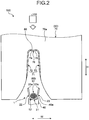
- FIG. 2 is a front view illustrating a terminal crimping device according to an embodiment.
- FIG. 3 is a perspective view of an upper mold according to an embodiment.
- FIG. 4 is a bottom view of an upper mold according to an embodiment.
- FIG. 5 is a cross-sectional view of an upper mold according to an embodiment.
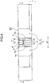
- FIG. 6 is a plan view of a terminal-equipped electric wire according to an embodiment.
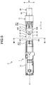
- FIG. 7 is a side view of a terminal-equipped electric wire according to an embodiment.
- FIG. 1 is a perspective view illustrating a crimp terminal and an electric wire an embodiment.
- FIG. 2 is a front view illustrating a terminal crimping device according to an embodiment.
- FIG. 3 is a perspective view of an upper mold according to an embodiment.
- FIG. 4 is a bottom view of an upper mold according to an embodiment.
- FIG. 5 is a cross-sectional
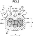
- FIG. 8 is a cross-sectional view of a terminal-equipped electric wire according to an embodiment.
- FIG. 5 illustrates a cross section taken along line V-V in FIG. 4 .
- FIG. 8 illustrates a cross section taken along line VIII-VIII of FIG. 6 .
- a crimp terminal 1 includes a terminal connecting portion 11, a core wire crimp portion 12, and a covering crimp portion 13.
- the terminal connecting portion 11, the core wire crimp portion 12, and the covering crimp portion 13 are arranged in this order in a longitudinal direction of the crimp terminal 1.
- the crimp terminal 1 is formed from a conductive metal plate (for example, a copper plate or a copper alloy plate) as a base material.
- the crimp terminal 1 is formed into a predetermined shape by punching or bending the base material.
- the surface of the crimp terminal 1 may be plated with tin (Sn) or the like.
- a connection direction with the counterpart terminal that is, an insertion direction with respect to the counterpart terminal is referred to as a first direction L.
- the first direction L is the longitudinal direction of the crimp terminal 1.
- a width direction of the crimp terminal 1 is referred to as a second direction W.
- the second direction W is orthogonal to the first direction L.
- a direction orthogonal to both the first direction L and the second direction W is referred to as a third direction H.
- the third direction H is a compression direction by an upper mold 50 when the crimp terminal 1 is crimped.
- the third direction H is a height direction of the crimp terminal 1.
- the terminal connecting portion 11 is a portion electrically connected to a counterpart terminal.
- the shape of the terminal connecting portion 11 of the present embodiment is a rectangular tube shape.
- the core wire crimp portion 12 is a portion that is crimped to a core wire 61 of an electric wire 60.
- the electric wire 60 has the core wire 61 and a covering 62. Examples of the material of the core wire 61 include copper and aluminum.
- the covering 62 at the end is removed to expose the core wire 61 by a predetermined length.
- the core wire 61 of the present embodiment is a group of a plurality of strands. Alternatively, the core wire 61 may be a single wire such as a coaxial cable.
- the crimp terminal 1 is crimped to the end of the electric wire 60 and thereby electrically connected to the exposed core wire 61.
- the shape of the core wire crimp portion 12 before being crimped to the core wire 61 is a U-shape as illustrated in FIG. 1 .
- the core wire crimp portion 12 includes a bottom wall portion 21, a first crimping piece 22, and a second crimping piece 23.
- the bottom wall portion 21 is a portion to be a bottom wall of the core wire crimp portion 12, and is supported by a lower mold 40 described below.
- the first crimping piece 22 and the second crimping piece 23 are a pair of conductor crimping pieces that are crimped to the core wire 61.
- the first crimping piece 22 is a side wall portion extending from one end of the bottom wall portion 21 in the width direction.
- the second crimping piece 23 is a side wall portion extending from the other end in the width direction of the bottom wall portion 21.
- the first crimping piece 22 and the second crimping piece 23 extend in a direction intersecting the width direction of the bottom wall portion 21.
- the first crimping piece 22 and the second crimping piece 23 face each other in the second direction W. As illustrated in FIGS. 1 and 2 , the distance between the first crimping piece 22 and the second crimping piece 23 increases from the bottom wall portion 21 side toward the tip side.
- the covering crimp portion 13 includes a bottom wall portion 31, a third crimping piece 32, and a fourth crimping piece 33.
- the shape of the covering crimp portion 13 before being crimped to the covering 62 is a U-shape as illustrated in FIG. 1 .
- the bottom wall portion 31 is a portion to be a bottom wall of the covering crimp portion 13.
- the third crimping piece 32 is a side wall portion extending from one end of the bottom wall portion 31 in the width direction.
- the fourth crimping piece 33 is a side wall portion extending from the other end of the bottom wall portion 31 in the width direction.
- the third crimping piece 32 and the fourth crimping piece 33 face each other in the second direction W. The distance between the third crimping piece 32 and the fourth crimping piece 33 increases from the bottom wall portion 31 side toward the tip side.
- the covering crimp portion 13 is crimped to the covering 62 by the lower mold 40 and the upper mold 50.
- the terminal connecting portion 11 and the core wire crimp portion 12 are connected via an intermediate portion 14.
- the height of the intermediate portion 14 is lower than any of the height of the terminal connecting portion 11 and the height of the core wire crimp portion 12.
- the core wire crimp portion 12 and the covering crimp portion 13 are connected via an intermediate portion 15.
- the intermediate portion 15 includes a bottom wall portion 15a and a side wall portion 15b.
- the bottom wall portion 15a connects the bottom wall portion 21 of the core wire crimp portion 12 and the bottom wall portion 31 of the covering crimp portion 13.
- the side wall portion 15b extends from both sides of the bottom wall portion 15a.
- One side wall portion 15b connects the first crimping piece 22 and the third crimping piece 32.
- the other side wall portion 15b connects the second crimping piece 23 and the fourth crimping piece 33.
- the height of the side wall portion 15b is lower than any of the heights of the crimping pieces 22 and 23 of the core wire crimp portion 12 and the heights of the crimping pieces 32 and 33 of the covering crimp portion 13.
- the electric wire 60 is mounted on the crimp terminal 1 such that an axial direction of the electric wire 60 is aligned with the longitudinal direction of the crimp terminal 1.
- a tip 61a of the core wire 61 is directed to the terminal connecting portion 11.
- the core wire 61 exposed to the outside from the covering 62 is mounted on the core wire crimp portion 12.
- the tip 61a of the core wire 61 may protrude from the core wire crimp portion 12 to the terminal connecting portion 11 side.
- the covering 62 of the electric wire 60 is mounted on the covering crimp portion 13.
- the electric wire 60 is installed such that a tip 62a of the covering 62 is positioned between the core wire crimp portion 12 and the covering crimp portion 13, for example.
- the core wire crimp portion 12 and the covering crimp portion 13 are crimped to the electric wire 60 by the lower mold 40 and the upper mold 50 as illustrated in FIG. 2 .
- the lower mold 40 and the upper mold 50 are components of a terminal crimping device 100.
- the lower mold 40 is a support-side mold that supports the core wire crimp portion 12 and the covering crimp portion 13 from below.
- a support surface 40a of the lower mold 40 supports an outer surface of the bottom wall portion 21 of the core wire crimp portion 12. Therefore, the first crimping piece 22 and the second crimping piece 23 are in a posture extending obliquely upward from the bottom wall portion 21 in a state where the core wire crimp portion 12 is supported by the lower mold 40.
- the lower mold 40 supports the covering crimp portion 13 from below in a similar manner.
- the upper mold 50 is a terminal crimping mold that sandwiches the crimp terminal 1 and the electric wire 60 between the lower mold 40 and oneself and thereby crimps the crimp terminal 1 to the electric wire 60.
- the upper mold 50 sandwiches the core wire crimp portion 12 and the core wire 61 between the lower mold 40 and oneself and thereby crimps the core wire crimp portion 12 to the core wire 61.
- the upper mold 50 sandwiches the covering crimp portion 13 and the covering 62 between the lower mold 40 and oneself and crimps the covering crimp portion 13 to the covering 62.
- the upper mold 50 is disposed above the lower mold 40.
- the upper mold 50 moves relative to the lower mold 40 in the third direction H.
- the terminal crimping device 100 includes a driving device 110 that moves the upper mold 50 up and down in the third direction H.
- the upper mold 50 of the present embodiment includes a first upper mold 70 illustrated in FIGS. 2 to 5 .
- the first upper mold 70 is a mold for crimping the core wire crimp portion 12 to the core wire 61.
- the upper mold 50 has a second upper mold (not illustrated).
- the second upper mold crimps the covering crimp portion 13 to the covering 62.
- the second upper mold moves up and down together with the first upper mold 70.
- the first upper mold 70 and the second upper mold may be integrated.
- the first upper mold 70 has a recessed first crimping surface 71.
- the first crimping surface 71 is a groove-like recessed surface provided on the lower surface of the first upper mold 70.
- the first upper mold 70 of the present embodiment crimps the core wire crimp portion 12 to the core wire 61 by a B-type crimping method (refer to FIG. 8 ).
- the first crimping surface 71 has a first wall surface 72 and a second wall surface 73. The first wall surface 72 and the second wall surface 73 face each other in the second direction W.
- the first wall surface 72 and the second wall surface 73 are positioned away from each other downward in the third direction H.
- the upper end portion of the first wall surface 72 includes a first curved surface 74.
- the upper end portion of the second wall surface 73 includes a second curved surface 75.
- the first curved surface 74 and the second curved surface 75 are surfaces facing the lower mold 40 in the third direction H, and are curved upward.
- the first curved surface 74 and the second curved surface 75 are located in an inner part of the first wall surface 72 and the second wall surface 73 farthest from the lower mold 40.
- the first curved surface 74 and the second curved surface 75 are adjacent in the second direction W.
- the boundary between the first curved surface 74 and the second curved surface 75 forms a ridge 76 projecting downward.
- the first curved surface 74 and the second curved surface 75 have boundary portions 74a and 75a, respectively.
- the boundary portions 74a and 75a are boundary lines at which the curvature changes.
- the radius of curvature of the first curved surface 74 changes at the boundary portion 74a. That is, the magnitude of the radius of curvature of the first curved surface 74 differs between the portion on one side in the second direction W and the portion on the other side in the second direction W across the boundary portion 74a.
- the radius of curvature of the portion on the ridge 76 side of the boundary portion 74a may be relatively small.
- the magnitude of the radius of curvature of the second curved surface 75 differs between the portion on one side in the second direction W and the portion on the other side in the second direction W across the boundary portion 75a.
- the radius of curvature of the portion on the ridge 76 side of the boundary portion 75a may be relatively small.
- the first curved surface 74 bends the first crimping piece 22 toward the second curved surface 75 and winds the first crimping piece 22 around the core wire 61.
- the second curved surface 75 bends the second crimping piece 23 toward the first curved surface 74 and winds the second crimping piece 23 around the core wire 61.
- This procedure forms a terminal-equipped electric wire 2 illustrated in FIGS. 6 to 8 .
- the core wire crimp portion 12 is crimped to the core wire 61 so as to be electrically connected to the core wire 61.
- the covering crimp portion 13 is crimped to the covering 62 to hold the covering 62. As illustrated in FIGS.
- an intermediate exposed portion 61b of the core wire 61 is exposed to the external space between the core wire crimp portion 12 and the covering crimp portion 13.
- the tip 61a of the core wire 61 protrudes from the core wire crimp portion 12 toward the terminal connecting portion 11 side.
- the first upper mold 70 of the present embodiment has a recess 77 as illustrated in FIGS. 3 to 5 .
- the recess 77 is provided on the first crimping surface 71 of the first upper mold 70.
- the recess 77 is recessed stepwise with respect to surrounding portions. In other words, the recess 77 is depressed with respect to the surrounding portions of the recess 77.
- the recess 77 includes a first recess 78 and a second recess 79.
- the first recess 78 is provided on the first curved surface 74 of the first wall surface 72. That is, the first recess 78 is disposed in a portion of the first wall surface 72, facing the lower mold 40 in the third direction H.
- the second recess 79 is provided on the second curved surface 75 of the second wall surface 73. That is, the second recess 79 is disposed in a portion of the second wall surface 73 facing the lower mold 40 in the third direction H.
- the first recess 78 and the second recess 79 extend in the third direction H.
- the first recess 78 and the second recess 79 have shapes each having a cylindrical space inside. That is, each of the first recess 78 and the second recess 79 has a circular cross-sectional shape of the section orthogonal to a depth direction.
- the cross-sectional shape of the first recess 78 and the cross-sectional shape of the second recess 79 are the same shape or substantially the same, for example.
- the depth of the first recess 78 is same as the depth of the second recess 79, for example.
- the first recess 78 and the second recess 79 are adjacent in the width direction, that is, the second direction W.
- the center position of the first recess 78 in the first direction L may be the same as the center position of the second recess 79 in the first direction L.
- a distance W1 from the tip of the ridge 76 to the central axis of the first recess 78 is equal to a distance W2 from the tip of the ridge 76 to the central axis of the second recess 79.
- Each of the distance W1 and the distance W2 is a distance in the second direction W.
- first recess 78 and the second recess 79 are arranged line-symmetrically with respect to the tip of the ridge 76.
- first recess 78 is arranged such that the central axis of the first recess 78 is located at the boundary portion 74a.
- second recess 79 is arranged such that the central axis of the second recess 79 is located at the boundary portion 75a.
- the first crimping surface 71 includes an inclined end surface 80.
- the inclined end surface 80 is provided at one end of the first crimping surface 71 in the first direction L.
- the inclined end surface 80 is inclined with respect to the first direction L and spreads in the first direction L toward a main surface 70a.
- the main surface 70a is one of a pair of main surfaces of the first upper mold 70 and is orthogonal to the first direction L.
- the main surface 70a is a surface facing the covering 62 side of the electric wire 60 in the crimping process.
- the main surface 70a is a surface located on the base side of the core wire 61 in the crimping process.
- the recess 77 is provided at a position near the main surface 70a in the first direction L, for example.
- the recess 77 is arranged so as not to overlap the inclined end surface 80.
- the core wire crimp portion 12 is crimped to the core wire 61 in a substantially B shape.
- the cross-sectional shape of each of the first crimping piece 22 and the second crimping piece 23 after crimping is a curved shape convex toward the side opposite to the bottom wall portion 21 side.
- the first crimping piece 22 has a curved portion 22b and a base portion 22c.
- the base portion 22c is a portion extending from the bottom wall portion 21 in the third direction H.
- the cross-sectional shape of the base portion 22c is a substantially linear shape.
- the curved portion 22b is a portion on the tip side of the base portion 22c in the first crimping piece 22.
- the curved portion 22b is curved such that a tip 22a faces the bottom wall portion 21 in the third direction H.
- the second crimping piece 23 includes a curved portion 23b and a base portion 23c.
- the base portion 23c is a portion extending from the bottom wall portion 21 in the third direction H.
- the cross-sectional shape of the base portion 23c is a substantially linear shape.
- the curved portion 23b is a portion on the tip side of the base portion 23c in the second crimping piece 23.
- the curved portion 23b is curved such that a tip 23a faces the bottom wall portion 21 in the third direction H.
- the first crimping piece 22 and the second crimping piece 23 are crimped to the core wire 61 while bringing an outer surface 22d of the first crimping piece 22 and an outer surface 23d of the second crimping piece 23 into contact with each other.
- a portion where the first crimping piece 22 and the second crimping piece 23 come in contact is formed into a groove 24.
- the groove 24 is a groove-shaped portion formed between the curved portions 22b and 23
- the terminal-equipped electric wire 2 of the present embodiment includes protrusions 25 and 26 respectively formed on the first crimping piece 22 and the second crimping piece 23.
- the first protrusion 25 is a protrusion arranged on the outer surface 22d of the first crimping piece 22.
- the first protrusion 25 protrudes stepwise with respect to surrounding portions on the outer surface 22d.
- the first protrusion 25 is formed at a top of the curved shape of the first crimping piece 22, for example.
- the second protrusion 26 is a protrusion arranged on the outer surface 23d of the second crimping piece 23.
- the second protrusion 26 protrudes stepwise with respect to surrounding portions on the outer surface 23d.
- the second protrusion 26 is formed at a top of the curved shape of the second crimping piece 23, for example.
- the first protrusion 25 and the second protrusion 26 protrude toward the side opposite to the bottom wall portion 21.
- the protruding direction of each of the first protrusion 25 and the second protrusion 26 is the third direction H, that is, a height direction of the crimp terminal 1.
- the first protrusion 25 and the second protrusion 26 may protrude in a direction slightly inclined with respect to the third direction H.
- the first protrusion 25 and the second protrusion 26 are formed in the crimping process.
- the core wire crimp portion 12 is crimped to the core wire 61 by the upper mold 50 and the lower mold 40.
- a part of the core wire crimp portion 12 enters the recess 77 when the core wire crimp portion 12 is crimped, whereby the first protrusion 25 and the second protrusion 26 are formed.
- a part of the first crimping piece 22 enters the first recess 78 in the crimping process, whereby the first protrusion 25 is formed.
- a part of the second crimping piece 23 enters the second recess 79 in the crimping process, whereby the second protrusion 26 is formed.
- the terminal-equipped electric wire 2 of the present embodiment can reduce the amount of lengthening of the crimp terminal 1, and can suppress variation in the amount of lengthening. According to the terminal-equipped electric wire 2 of the present embodiment, it is possible to suppress a situation in which the crimp terminal 1 jumps out of a cavity such as an electric junction box.
- the first protrusion 25 and the second protrusion 26 of the present embodiment have cylindrical shapes.
- Each of the first protrusion 25 and the second protrusion 26 has a circular cross-sectional shape in a cross section orthogonal to the protrusion direction.
- the cross-sectional shape of the first protrusion 25 and the cross-sectional shape of the second protrusion 26 may have a same shape or substantially the same, for example.
- the protruding height of the first protrusion 25 and the protruding height of the second protrusion 26 are the same, for example.
- a tip 26a of the second protrusion 26 is located at a position lower than a top 13a of the covering crimp portion 13. That is, a distance in the third direction H from the bottom wall portion 21 to the tip 26a is shorter than a distance in the third direction H from the bottom wall portion 31 to the top 13a.
- the tip 26a is located at a position lower than a top 11a of the terminal connecting portion 11.
- the height position of a tip 25a (refer to FIG. 8 ) of the first protrusion 25 is substantially the same as the height position of the tip 26a. That is, the tip 25a is at a position lower than any of the top 13a of the covering crimp portion 13 and the top 11a of the terminal connecting portion 11. Accordingly, the two protrusions 25 and 26 would not easily interfere with the wall surface of a cavity when the crimp terminal 1 is stored in the cavity.
- the first protrusion 25 and the second protrusion 26 face each other in the width direction, that is, the second direction W.
- the center position of the first protrusion 25 in the first direction L may be the same as the center position of the second protrusion 26 in the first direction L.
- a distance W3 from a center line C1 of the terminal-equipped electric wire 2 to the center of the first protrusion 25 is equal to a distance W4 from the center line C1 to the center of the second protrusion 26. That is, in a plan view of the terminal-equipped electric wire 2, the first protrusion 25 and the second protrusion 26 are arranged line-symmetrically with respect to the center line C1.
- the positions of the first protrusion 25 and the second protrusion 26 in the first direction L may be a position on the covering crimp portion 13 side of the center of the core wire crimp portion 12, or may be a position on the terminal connecting portion 11 side of the center, for example.
- the first protrusion 25 and the second protrusion 26 are preferably formed in a region excluding a bell-mouth portion 27 in the core wire crimp portion 12.
- the bell-mouth portion 27 is a portion formed corresponding to the inclined end surface 80 of the first upper mold 70.
- the bell-mouth portion 27 is formed at the covering crimp portion 13-side end of the core wire crimp portion 12.
- the outer surface of the bell-mouth portion 27 is an inclined surface that is inclined with respect to the first direction L.
- the bell-mouth portion 27 is inclined so as to expand in the first direction L toward the covering crimp portion 13.
- the first protrusion 25 of the present embodiment is formed in a region excluding the bell-mouth portion 27 in the first crimping piece 22.
- the second protrusion 26 is formed in a region excluding the bell-mouth portion 27 in the second crimping piece 23.
- the recess 77 is separated from the inclined end surface 80 as illustrated in FIG. 4 or the like. That is, the recess 77 is formed in a region excluding the inclined end surface 80 on the first curved surface 74 and the second curved surface 75.
- the terminal-equipped electric wire 2 of the present embodiment includes the electric wire 60 and the crimp terminal 1.
- the crimp terminal 1 includes the core wire crimp portion 12 that is crimped to the core wire 61 of the electric wire 60.
- the core wire crimp portion 12 includes the bottom wall portion 21 and the crimping pieces 22 and 23.
- the crimping pieces 22 and 23 extend in a direction intersecting the bottom wall portion 21 from the end of the bottom wall portion 21 in the second direction W, and are wound around the core wire 61.
- each of the crimping pieces 22 and 23 is a curved shape that is convex toward the side opposite to the bottom wall portion 21.
- the curved portions 22b and 23b of the crimping pieces 22 and 23 respectively include the protrusions 25 and 26 protruding stepwise with respect to surrounding portions.
- the lengthening of the crimp terminal 1 is suppressed in the crimping process. Since the volume corresponding to the protrusions 25 and 26 is released, the lengthening of the crimp terminal 1 in the first direction L is suppressed.
- the terminal-equipped electric wire 2 of the present embodiment achieves an effect that the lengthening of the crimp terminal due to crimping is suppressed. Furthermore, since the lengthening of the crimp terminal 1 is suppressed, it is possible to reduce variation in the length of the crimp terminal 1 in the first direction L.
- the bell-mouth portions 27 are formed at the end portions in the first direction L of the crimping pieces 22 and 23.
- the protrusions 25 and 26 are formed in regions excluding the bell-mouth portion 27 in the crimping pieces 22 and 23.
- the protrusions 25 and 26 are formed in a region on the terminal connecting portion 11 side of the bell-mouth portion 27 in the first direction L. Forming the protrusions 25 and 26 in the region excluding the bell-mouth portion 27 would prevent interference between the formation of the bell-mouth portion 27 and the formation of the protrusions 25 and 26.
- the crimping pieces 22 and 23 of the present embodiment include the first crimping piece 22 and the second crimping piece 23.
- the first crimping piece 22 extends from one end of the bottom wall portion 21 in the width direction, while the second crimping piece 23 extends from the other end of the bottom wall portion 21 in the width direction.
- the core wire crimp portion 12 is crimped to the core wire 61 while bringing the outer surface 22d of the first crimping piece 22 and the outer surface 23d of the second crimping piece 23 into contact with each other.
- the protrusions 25 and 26 include the first protrusion 25 formed on the outer surface 22d of the first crimping piece 22 and the second protrusion 26 formed on the outer surface 23d of the second crimping piece 23.
- the first protrusion 25 and the second protrusion 26 face each other in the width direction of the bottom wall portion 21. This ensures symmetry in the crimp terminal 1, leading to reduction of variations in the performance of the crimp terminal 1. For example, it is possible to reduce the variation between the amount of lengthening on the first crimping piece 22 side and the amount of lengthening on the second crimping piece 23 side.
- the crimp terminal 1 of the present embodiment has the covering crimp portion 13 that is crimped to the covering 62 of the electric wire 60.
- the tips 25a and 26a of the protrusions 25 and 26 are located lower than the top 13a of the covering crimp portion 13. Therefore, the protrusions 25 and 26 would not easily interfere with the cavity when the crimp terminal 1 is stored in the cavity.
- the terminal crimping device 100 includes the lower mold 40 and the upper mold 50.
- the lower mold 40 supports the crimp terminal 1 having the core wire crimp portion 12 crimped to the core wire 61 of the electric wire 60, from below.
- the upper mold 50 has the first crimping surface 71 for winding the core wire crimp portion 12 around the core wire 61, and descending toward the lower mold 40 to crimp the crimp terminal 1 to the electric wire 60.
- the portion facing the lower mold 40 has the recess 77 that is recessed stepwise with respect to the surrounding portion.
- the first curved surface 74 and the second curved surface 75 have the recess 77.
- the upper mold 50 including the recess 77 can release a part of the core wire crimp portion 12 to the recess 77 in the crimping process, making is possible to suppress the lengthening of the crimp terminal 1.
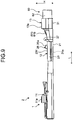
- FIG. 9 is a side view of a terminal-equipped electric wire according to the first modification of an embodiment.
- the terminal-equipped electric wire 2 illustrated in FIG. 9 has a recess 21a in the bottom wall portion 21.
- the recess 21a is formed by the lower mold 40 in the crimping process, for example.
- the lower mold 40 having a protrusion on the support surface 40a is used in the crimping process.
- the recess 21a extends in the first direction L.
- the recess 21a is formed in the center portion of the bottom wall portion 21 in the second direction W, for example.
- the first protrusion 25 and the second protrusion 26 are preferably arranged so as not to overlap the recess 21a.
- the first protrusion 25 and the second protrusion 26 are formed at a position on the covering crimp portion 13 side of the recess 21a.
- the first protrusion 25 and the second protrusion 26 may be formed at a position on the terminal connecting portion 11 side of the recess 21a. Since there is no overlapping between the position of the recess 21a and the position of the protrusions 25 and 26 in the first direction L, it is possible to suppress the reduction in strength of the core wire crimp portion 12.
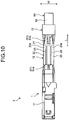
- FIG. 10 is a plan view of a terminal-equipped electric wire according to the second modification of an embodiment.
- FIG. 11 is a side view of the terminal-equipped electric wire according to the second modification of an embodiment.
- the second modification of an embodiment differs from the above embodiment in the shape of the protrusions 25 and 26, for example.
- the protrusions 25 and 26 according to the second modification of the embodiment extend in the first direction L.
- the first protrusion 25 and the second protrusion 26 are formed in the first direction L from one end to the other end of the core wire crimp portion 12 excluding the bell-mouth portion 27.
- the cross-sectional shape of the protrusions 25 and 26 in the cross section orthogonal to the first direction L is a rectangle, for example.
- the cross-sectional shape of the protrusions 25 and 26 may be trapezoidal or semicircular. Forming the first protrusion 25 and the second protrusion 26 in a wide range in the first direction L makes it possible to increase the volume of the first protrusion 25 and the second protrusion 26. Accordingly, with the terminal-equipped electric wire 2 according to the second modification of the embodiment, it is possible to suppress the lengthening of the crimp terminal 1.
- FIG. 12 is a cross-sectional view of a terminal-equipped electric wire according to the third modification of an embodiment.
- the third modification of an embodiment differs from the above embodiment in that the first crimping piece 22 and the second crimping piece 23 are crimped while overlapping each other.
- the first crimping piece 22 and the second crimping piece 23 are wound around the core wire 61 while overlapping each other.
- the first crimping piece 22 and the second crimping piece 23 integrally cover the core wire 61 from the tip 61a to the covering 62. That is, the core wire crimp portion 12 and the covering crimp portion 13 of the above embodiment are integrated.
- the crimp terminal 1 is crimped to the core wire 61 so that the second crimping piece 23 overlaps the outside of the first crimping piece 22.
- a protrusion 28 is formed on the second crimping piece 23 positioned on the outside.
- the protrusion 28 is formed at a top of the second crimping piece 23, for example.
- the protrusion 28 may be formed at a position farthest from the bottom wall portion 21 on the outer surface 23d of the second crimping piece 23.
- the protrusion 28 may be formed in plurality on the second crimping piece 23.
- An anticorrosion resin film may be formed on the terminal-equipped electric wire 2.
- the resin film is formed so as to cover the tip 61a of the core wire 61 and the intermediate exposed portion 61b, for example.
- the resin film may be further formed in the groove 24 of the core wire crimp portion 12.
- the shape, arrangement, number, or the like, of the protrusions are not limited to the shape, arrangement, number, or the like, of the protrusions 25, 26, or 28 exemplified in the above embodiment and the modification.
- the shape, arrangement, number, or the like, of the protrusions are appropriately determined in accordance with the crimped shape of the crimp terminal 1 with respect to the electric wire 60.
- a protrusion protruding stepwise with respect to surrounding portions is formed on a curved portion of a crimping piece. According to the terminal-equipped electric wire of the present embodiment, it is possible to achieve an effect of releasing the volume corresponding to the protrusion formed at the time of crimping, leading to suppression of the lengthening of the crimp terminal.
Landscapes
- Engineering & Computer Science (AREA)
- Manufacturing & Machinery (AREA)
- Connections Effected By Soldering, Adhesion, Or Permanent Deformation (AREA)
- Manufacturing Of Electrical Connectors (AREA)
Abstract
A terminal-equipped electric wire (2) includes: an electric wire; and a crimp terminal (1) including a core wire crimp portion (12) crimped to a core wire (61) of the electric wire, in which the core wire crimp portion (12) includes: a bottom wall portion (21); and crimping pieces (22 and 23) that extend in a direction intersecting the bottom wall portion (21) from an end of the bottom wall portion (21) in a width direction and that are wound around the core wire (61), a cross-sectional shape of the crimping piece (22 and 23) is a curved shape convex toward a side opposite to the bottom wall portion (21), and curved portions (22b and 23b) of the crimping piece (22 and 23) respectively include protrusions (25 and 26) formed to protrude stepwise with respect to surrounding portions.
Description
- The present invention relates to a terminal-equipped electric wire and a terminal crimping device.
- Conventionally, there have been techniques for crimping a terminal to an electric wire. Japanese Patent Application Laid-open No.
2010-80194 2010-80194 2010-80194 - Here, there is still room for improvement in suppressing the lengthening of the crimp terminal due to crimping.
- An object of the present invention is to provide a terminal-equipped electric wire and a terminal crimping device capable of suppressing lengthening of the crimp terminal due to crimping.
- In order to achieve the above mentioned object, a terminal-equipped electric wire according to one aspect of the present invention includes an electric wire; and a crimp terminal including a core wire crimp portion crimped to a core wire of the electric wire, wherein the core wire crimp portion includes a bottom wall portion, and a crimping piece that extends in a direction intersecting the bottom wall portion from an end of the bottom wall portion in a width direction and that is wound around the core wire, a cross-sectional shape of the crimping piece is a curved shape convex toward a side opposite to the bottom wall portion, and a curved portion of the crimping piece includes a protrusion formed to protrude stepwise with respect to surrounding portions.
- The above and other objects, features, advantages and technical and industrial significance of this invention will be better understood by reading the following detailed description of presently preferred embodiments of the invention, when considered in connection with the accompanying drawings.
-
-
FIG. 1 is a perspective view illustrating a crimp terminal and an electric wire according to an embodiment; -
FIG. 2 is a front view illustrating a terminal crimping device according to an embodiment; -
FIG. 3 is a perspective view of an upper mold according to an embodiment; -
FIG. 4 is a bottom view of an upper mold according to an embodiment; -
FIG. 5 is a cross-sectional view of an upper mold according to an embodiment; -
FIG. 6 is a plan view of a terminal-equipped electric wire according to an embodiment; -
FIG. 7 is a side view of the terminal-equipped electric wire according to an embodiment; -
FIG. 8 is a cross-sectional view of a terminal-equipped electric wire according to an embodiment; -
FIG. 9 is a side view of a terminal-equipped electric wire according to a first modification of an embodiment; -
FIG. 10 is a plan view of a terminal-equipped electric wire according to a second modification of an embodi-ment; -
FIG. 11 is a side view of a terminal-equipped electric wire according to the second modification of an embodiment; and -
FIG. 12 is a cross-sectional view of a terminal-equipped electric wire according to a third modification of an embodiment. - Hereinafter, a terminal-equipped electric wire and terminal crimping device according to an embodiment of the present invention will be described in detail with reference to the drawings. Note that the present invention is not limited by the present embodiment. Moreover, components in the following embodiment include those that can be easily assumed by those skilled in the art or substantially identical.
- An embodiment will be described with reference to
FIGS. 1 to 8 . The present embodiment relates to a terminal-equipped electric wire and a terminal crimping device.FIG. 1 is a perspective view illustrating a crimp terminal and an electric wire an embodiment.FIG. 2 is a front view illustrating a terminal crimping device according to an embodiment.FIG. 3 is a perspective view of an upper mold according to an embodiment.FIG. 4 is a bottom view of an upper mold according to an embodiment.FIG. 5 is a cross-sectional view of an upper mold according to an embodiment.FIG. 6 is a plan view of a terminal-equipped electric wire according to an embodiment.FIG. 7 is a side view of a terminal-equipped electric wire according to an embodiment.FIG. 8 is a cross-sectional view of a terminal-equipped electric wire according to an embodiment.FIG. 5 illustrates a cross section taken along line V-V inFIG. 4 .FIG. 8 illustrates a cross section taken along line VIII-VIII ofFIG. 6 . - As illustrated in
FIG. 1 , acrimp terminal 1 according to the present embodiment includes a terminal connectingportion 11, a corewire crimp portion 12, and a coveringcrimp portion 13. Theterminal connecting portion 11, the corewire crimp portion 12, and the coveringcrimp portion 13 are arranged in this order in a longitudinal direction of thecrimp terminal 1. Thecrimp terminal 1 is formed from a conductive metal plate (for example, a copper plate or a copper alloy plate) as a base material. Thecrimp terminal 1 is formed into a predetermined shape by punching or bending the base material. The surface of thecrimp terminal 1 may be plated with tin (Sn) or the like. - In the description of the
crimp terminal 1 in the present specification, a connection direction with the counterpart terminal, that is, an insertion direction with respect to the counterpart terminal is referred to as a first direction L. The first direction L is the longitudinal direction of thecrimp terminal 1. A width direction of thecrimp terminal 1 is referred to as a second direction W. The second direction W is orthogonal to the first direction L. In thecrimp terminal 1, a direction orthogonal to both the first direction L and the second direction W is referred to as a third direction H. The third direction H is a compression direction by anupper mold 50 when thecrimp terminal 1 is crimped. The third direction H is a height direction of thecrimp terminal 1. - The terminal connecting
portion 11 is a portion electrically connected to a counterpart terminal. The shape of theterminal connecting portion 11 of the present embodiment is a rectangular tube shape. The corewire crimp portion 12 is a portion that is crimped to acore wire 61 of anelectric wire 60. Theelectric wire 60 has thecore wire 61 and acovering 62. Examples of the material of thecore wire 61 include copper and aluminum. In theelectric wire 60 to be crimped by thecrimp terminal 1, the covering 62 at the end is removed to expose thecore wire 61 by a predetermined length. Thecore wire 61 of the present embodiment is a group of a plurality of strands. Alternatively, thecore wire 61 may be a single wire such as a coaxial cable. Thecrimp terminal 1 is crimped to the end of theelectric wire 60 and thereby electrically connected to the exposedcore wire 61. - The shape of the core
wire crimp portion 12 before being crimped to thecore wire 61 is a U-shape as illustrated inFIG. 1 . The corewire crimp portion 12 includes abottom wall portion 21, afirst crimping piece 22, and asecond crimping piece 23. Thebottom wall portion 21 is a portion to be a bottom wall of the corewire crimp portion 12, and is supported by alower mold 40 described below. The first crimpingpiece 22 and the second crimpingpiece 23 are a pair of conductor crimping pieces that are crimped to thecore wire 61. The first crimpingpiece 22 is a side wall portion extending from one end of thebottom wall portion 21 in the width direction. The second crimpingpiece 23 is a side wall portion extending from the other end in the width direction of thebottom wall portion 21. The first crimpingpiece 22 and the second crimpingpiece 23 extend in a direction intersecting the width direction of thebottom wall portion 21. The first crimpingpiece 22 and the second crimpingpiece 23 face each other in the second direction W. As illustrated inFIGS. 1 and2 , the distance between the first crimpingpiece 22 and the second crimpingpiece 23 increases from thebottom wall portion 21 side toward the tip side. - As illustrated in
FIG. 1 , thecovering crimp portion 13 includes abottom wall portion 31, a third crimpingpiece 32, and a fourth crimpingpiece 33. The shape of thecovering crimp portion 13 before being crimped to the covering 62 is a U-shape as illustrated inFIG. 1 . Thebottom wall portion 31 is a portion to be a bottom wall of thecovering crimp portion 13. The third crimpingpiece 32 is a side wall portion extending from one end of thebottom wall portion 31 in the width direction. The fourth crimpingpiece 33 is a side wall portion extending from the other end of thebottom wall portion 31 in the width direction. The third crimpingpiece 32 and the fourth crimpingpiece 33 face each other in the second direction W. The distance between the third crimpingpiece 32 and the fourth crimpingpiece 33 increases from thebottom wall portion 31 side toward the tip side. Thecovering crimp portion 13 is crimped to the covering 62 by thelower mold 40 and theupper mold 50. - The
terminal connecting portion 11 and the corewire crimp portion 12 are connected via an intermediate portion 14. The height of the intermediate portion 14 is lower than any of the height of theterminal connecting portion 11 and the height of the corewire crimp portion 12. The corewire crimp portion 12 and thecovering crimp portion 13 are connected via anintermediate portion 15. Theintermediate portion 15 includes abottom wall portion 15a and aside wall portion 15b. Thebottom wall portion 15a connects thebottom wall portion 21 of the corewire crimp portion 12 and thebottom wall portion 31 of thecovering crimp portion 13. Theside wall portion 15b extends from both sides of thebottom wall portion 15a. Oneside wall portion 15b connects the first crimpingpiece 22 and the third crimpingpiece 32. The otherside wall portion 15b connects the second crimpingpiece 23 and the fourth crimpingpiece 33. The height of theside wall portion 15b is lower than any of the heights of the crimpingpieces wire crimp portion 12 and the heights of the crimpingpieces covering crimp portion 13. - As illustrated in
FIG. 1 , theelectric wire 60 is mounted on thecrimp terminal 1 such that an axial direction of theelectric wire 60 is aligned with the longitudinal direction of thecrimp terminal 1. In a state mounted on thecrimp terminal 1, atip 61a of thecore wire 61 is directed to theterminal connecting portion 11. Thecore wire 61 exposed to the outside from the covering 62 is mounted on the corewire crimp portion 12. At this time, thetip 61a of thecore wire 61 may protrude from the corewire crimp portion 12 to theterminal connecting portion 11 side. The covering 62 of theelectric wire 60 is mounted on thecovering crimp portion 13. Theelectric wire 60 is installed such that atip 62a of the covering 62 is positioned between the corewire crimp portion 12 and thecovering crimp portion 13, for example. - The core
wire crimp portion 12 and thecovering crimp portion 13 are crimped to theelectric wire 60 by thelower mold 40 and theupper mold 50 as illustrated inFIG. 2 . Thelower mold 40 and theupper mold 50 are components of a terminal crimpingdevice 100. Thelower mold 40 is a support-side mold that supports the corewire crimp portion 12 and thecovering crimp portion 13 from below. Asupport surface 40a of thelower mold 40 supports an outer surface of thebottom wall portion 21 of the corewire crimp portion 12. Therefore, the first crimpingpiece 22 and the second crimpingpiece 23 are in a posture extending obliquely upward from thebottom wall portion 21 in a state where the corewire crimp portion 12 is supported by thelower mold 40. Thelower mold 40 supports thecovering crimp portion 13 from below in a similar manner. - The
upper mold 50 is a terminal crimping mold that sandwiches thecrimp terminal 1 and theelectric wire 60 between thelower mold 40 and oneself and thereby crimps thecrimp terminal 1 to theelectric wire 60. Theupper mold 50 sandwiches the corewire crimp portion 12 and thecore wire 61 between thelower mold 40 and oneself and thereby crimps the corewire crimp portion 12 to thecore wire 61. In addition, theupper mold 50 sandwiches thecovering crimp portion 13 and the covering 62 between thelower mold 40 and oneself and crimps thecovering crimp portion 13 to thecovering 62. As illustrated inFIG. 2 , theupper mold 50 is disposed above thelower mold 40. Theupper mold 50 moves relative to thelower mold 40 in the third direction H. Theterminal crimping device 100 includes adriving device 110 that moves theupper mold 50 up and down in the third direction H. - The
upper mold 50 of the present embodiment includes a firstupper mold 70 illustrated inFIGS. 2 to 5 . The firstupper mold 70 is a mold for crimping the corewire crimp portion 12 to thecore wire 61. Apart from the firstupper mold 70, theupper mold 50 has a second upper mold (not illustrated). The second upper mold crimps thecovering crimp portion 13 to thecovering 62. The second upper mold moves up and down together with the firstupper mold 70. The firstupper mold 70 and the second upper mold may be integrated. - As illustrated in
FIG. 2 , the firstupper mold 70 has a recessed first crimpingsurface 71. The first crimpingsurface 71 is a groove-like recessed surface provided on the lower surface of the firstupper mold 70. The firstupper mold 70 of the present embodiment crimps the corewire crimp portion 12 to thecore wire 61 by a B-type crimping method (refer toFIG. 8 ). As illustrated inFIG. 2 , the first crimpingsurface 71 has afirst wall surface 72 and asecond wall surface 73. Thefirst wall surface 72 and thesecond wall surface 73 face each other in the second direction W. - The
first wall surface 72 and thesecond wall surface 73 are positioned away from each other downward in the third direction H. The upper end portion of thefirst wall surface 72 includes a firstcurved surface 74. The upper end portion of thesecond wall surface 73 includes a secondcurved surface 75. The firstcurved surface 74 and the secondcurved surface 75 are surfaces facing thelower mold 40 in the third direction H, and are curved upward. The firstcurved surface 74 and the secondcurved surface 75 are located in an inner part of thefirst wall surface 72 and thesecond wall surface 73 farthest from thelower mold 40. The firstcurved surface 74 and the secondcurved surface 75 are adjacent in the second direction W. The boundary between the firstcurved surface 74 and the secondcurved surface 75 forms aridge 76 projecting downward. - As illustrated in
FIGS. 3 and4 , the firstcurved surface 74 and the secondcurved surface 75 haveboundary portions boundary portions curved surface 74 changes at theboundary portion 74a. That is, the magnitude of the radius of curvature of the firstcurved surface 74 differs between the portion on one side in the second direction W and the portion on the other side in the second direction W across theboundary portion 74a. In the firstcurved surface 74, the radius of curvature of the portion on theridge 76 side of theboundary portion 74a may be relatively small. - The magnitude of the radius of curvature of the second
curved surface 75 differs between the portion on one side in the second direction W and the portion on the other side in the second direction W across theboundary portion 75a. In the secondcurved surface 75, the radius of curvature of the portion on theridge 76 side of theboundary portion 75a may be relatively small. - The first
curved surface 74 bends the first crimpingpiece 22 toward the secondcurved surface 75 and winds the first crimpingpiece 22 around thecore wire 61. The secondcurved surface 75 bends the second crimpingpiece 23 toward the firstcurved surface 74 and winds the second crimpingpiece 23 around thecore wire 61. This procedure forms a terminal-equippedelectric wire 2 illustrated inFIGS. 6 to 8 . In a crimping process, the corewire crimp portion 12 is crimped to thecore wire 61 so as to be electrically connected to thecore wire 61. In the crimping process, thecovering crimp portion 13 is crimped to the covering 62 to hold thecovering 62. As illustrated inFIGS. 6 and7 , an intermediate exposedportion 61b of thecore wire 61 is exposed to the external space between the corewire crimp portion 12 and thecovering crimp portion 13. Thetip 61a of thecore wire 61 protrudes from the corewire crimp portion 12 toward theterminal connecting portion 11 side. - The first
upper mold 70 of the present embodiment has arecess 77 as illustrated inFIGS. 3 to 5 . Therecess 77 is provided on the first crimpingsurface 71 of the firstupper mold 70. Therecess 77 is recessed stepwise with respect to surrounding portions. In other words, therecess 77 is depressed with respect to the surrounding portions of therecess 77. Therecess 77 includes afirst recess 78 and asecond recess 79. Thefirst recess 78 is provided on the firstcurved surface 74 of thefirst wall surface 72. That is, thefirst recess 78 is disposed in a portion of thefirst wall surface 72, facing thelower mold 40 in the third direction H. Thesecond recess 79 is provided on the secondcurved surface 75 of thesecond wall surface 73. That is, thesecond recess 79 is disposed in a portion of thesecond wall surface 73 facing thelower mold 40 in the third direction H. Thefirst recess 78 and thesecond recess 79 extend in the third direction H. - The
first recess 78 and thesecond recess 79 according to the present embodiment have shapes each having a cylindrical space inside. That is, each of thefirst recess 78 and thesecond recess 79 has a circular cross-sectional shape of the section orthogonal to a depth direction. The cross-sectional shape of thefirst recess 78 and the cross-sectional shape of thesecond recess 79 are the same shape or substantially the same, for example. The depth of thefirst recess 78 is same as the depth of thesecond recess 79, for example. - The
first recess 78 and thesecond recess 79 are adjacent in the width direction, that is, the second direction W. The center position of thefirst recess 78 in the first direction L may be the same as the center position of thesecond recess 79 in the first direction L. In the present embodiment, as illustrated inFIGS. 4 and5 , a distance W1 from the tip of theridge 76 to the central axis of thefirst recess 78 is equal to a distance W2 from the tip of theridge 76 to the central axis of thesecond recess 79. Each of the distance W1 and the distance W2 is a distance in the second direction W. That is, thefirst recess 78 and thesecond recess 79 are arranged line-symmetrically with respect to the tip of theridge 76. For example, thefirst recess 78 is arranged such that the central axis of thefirst recess 78 is located at theboundary portion 74a. For example, thesecond recess 79 is arranged such that the central axis of thesecond recess 79 is located at theboundary portion 75a. - The first crimping
surface 71 includes aninclined end surface 80. Theinclined end surface 80 is provided at one end of the first crimpingsurface 71 in the first direction L. Theinclined end surface 80 is inclined with respect to the first direction L and spreads in the first direction L toward amain surface 70a. Themain surface 70a is one of a pair of main surfaces of the firstupper mold 70 and is orthogonal to the first direction L. Themain surface 70a is a surface facing the covering 62 side of theelectric wire 60 in the crimping process. In other words, themain surface 70a is a surface located on the base side of thecore wire 61 in the crimping process. Therecess 77 is provided at a position near themain surface 70a in the first direction L, for example. Therecess 77 is arranged so as not to overlap theinclined end surface 80. - As illustrated in
FIG. 8 , the corewire crimp portion 12 is crimped to thecore wire 61 in a substantially B shape. The cross-sectional shape of each of the first crimpingpiece 22 and the second crimpingpiece 23 after crimping is a curved shape convex toward the side opposite to thebottom wall portion 21 side. More specifically, the first crimpingpiece 22 has acurved portion 22b and abase portion 22c. Thebase portion 22c is a portion extending from thebottom wall portion 21 in the third direction H. The cross-sectional shape of thebase portion 22c is a substantially linear shape. Thecurved portion 22b is a portion on the tip side of thebase portion 22c in the first crimpingpiece 22. Thecurved portion 22b is curved such that atip 22a faces thebottom wall portion 21 in the third direction H. - The second crimping
piece 23 includes acurved portion 23b and abase portion 23c. Thebase portion 23c is a portion extending from thebottom wall portion 21 in the third direction H. The cross-sectional shape of thebase portion 23c is a substantially linear shape. Thecurved portion 23b is a portion on the tip side of thebase portion 23c in the second crimpingpiece 23. Thecurved portion 23b is curved such that atip 23a faces thebottom wall portion 21 in the third direction H. The first crimpingpiece 22 and the second crimpingpiece 23 are crimped to thecore wire 61 while bringing anouter surface 22d of the first crimpingpiece 22 and anouter surface 23d of the second crimpingpiece 23 into contact with each other. A portion where the first crimpingpiece 22 and the second crimpingpiece 23 come in contact is formed into agroove 24. Thegroove 24 is a groove-shaped portion formed between thecurved portions - As illustrated in
FIGS. 6 to 8 , in the terminal-equippedelectric wire 2 of the present embodiment includesprotrusions piece 22 and the second crimpingpiece 23. Thefirst protrusion 25 is a protrusion arranged on theouter surface 22d of the first crimpingpiece 22. Thefirst protrusion 25 protrudes stepwise with respect to surrounding portions on theouter surface 22d. Thefirst protrusion 25 is formed at a top of the curved shape of the first crimpingpiece 22, for example. Thesecond protrusion 26 is a protrusion arranged on theouter surface 23d of the second crimpingpiece 23. Thesecond protrusion 26 protrudes stepwise with respect to surrounding portions on theouter surface 23d. Thesecond protrusion 26 is formed at a top of the curved shape of the second crimpingpiece 23, for example. - The
first protrusion 25 and thesecond protrusion 26 protrude toward the side opposite to thebottom wall portion 21. The protruding direction of each of thefirst protrusion 25 and thesecond protrusion 26 is the third direction H, that is, a height direction of thecrimp terminal 1. Thefirst protrusion 25 and thesecond protrusion 26 may protrude in a direction slightly inclined with respect to the third direction H. - The
first protrusion 25 and thesecond protrusion 26 are formed in the crimping process. In the crimping process, the corewire crimp portion 12 is crimped to thecore wire 61 by theupper mold 50 and thelower mold 40. A part of the corewire crimp portion 12 enters therecess 77 when the corewire crimp portion 12 is crimped, whereby thefirst protrusion 25 and thesecond protrusion 26 are formed. A part of the first crimpingpiece 22 enters thefirst recess 78 in the crimping process, whereby thefirst protrusion 25 is formed. A part of the second crimpingpiece 23 enters thesecond recess 79 in the crimping process, whereby thesecond protrusion 26 is formed. Entrance of the part of the corewire crimp portion 12 into therecess 77 suppresses the lengthening of thecrimp terminal 1 in the crimping process. Accordingly, the terminal-equippedelectric wire 2 of the present embodiment can reduce the amount of lengthening of thecrimp terminal 1, and can suppress variation in the amount of lengthening. According to the terminal-equippedelectric wire 2 of the present embodiment, it is possible to suppress a situation in which thecrimp terminal 1 jumps out of a cavity such as an electric junction box. - As illustrated in
FIGS. 6 to 8 , thefirst protrusion 25 and thesecond protrusion 26 of the present embodiment have cylindrical shapes. Each of thefirst protrusion 25 and thesecond protrusion 26 has a circular cross-sectional shape in a cross section orthogonal to the protrusion direction. The cross-sectional shape of thefirst protrusion 25 and the cross-sectional shape of thesecond protrusion 26 may have a same shape or substantially the same, for example. The protruding height of thefirst protrusion 25 and the protruding height of thesecond protrusion 26 are the same, for example. - As illustrated in
FIG. 7 , atip 26a of thesecond protrusion 26 is located at a position lower than a top 13a of thecovering crimp portion 13. That is, a distance in the third direction H from thebottom wall portion 21 to thetip 26a is shorter than a distance in the third direction H from thebottom wall portion 31 to the top 13a. Thetip 26a is located at a position lower than a top 11a of theterminal connecting portion 11. The height position of atip 25a (refer toFIG. 8 ) of thefirst protrusion 25 is substantially the same as the height position of thetip 26a. That is, thetip 25a is at a position lower than any of the top 13a of thecovering crimp portion 13 and the top 11a of theterminal connecting portion 11. Accordingly, the twoprotrusions crimp terminal 1 is stored in the cavity. - The
first protrusion 25 and thesecond protrusion 26 face each other in the width direction, that is, the second direction W. The center position of thefirst protrusion 25 in the first direction L may be the same as the center position of thesecond protrusion 26 in the first direction L. In the present embodiment, as illustrated inFIG. 6 , a distance W3 from a center line C1 of the terminal-equippedelectric wire 2 to the center of thefirst protrusion 25 is equal to a distance W4 from the center line C1 to the center of thesecond protrusion 26. That is, in a plan view of the terminal-equippedelectric wire 2, thefirst protrusion 25 and thesecond protrusion 26 are arranged line-symmetrically with respect to the center line C1. - The positions of the
first protrusion 25 and thesecond protrusion 26 in the first direction L may be a position on thecovering crimp portion 13 side of the center of the corewire crimp portion 12, or may be a position on theterminal connecting portion 11 side of the center, for example. Thefirst protrusion 25 and thesecond protrusion 26 are preferably formed in a region excluding a bell-mouth portion 27 in the corewire crimp portion 12. The bell-mouth portion 27 is a portion formed corresponding to theinclined end surface 80 of the firstupper mold 70. The bell-mouth portion 27 is formed at the covering crimp portion 13-side end of the corewire crimp portion 12. The outer surface of the bell-mouth portion 27 is an inclined surface that is inclined with respect to the first direction L. The bell-mouth portion 27 is inclined so as to expand in the first direction L toward thecovering crimp portion 13. - The
first protrusion 25 of the present embodiment is formed in a region excluding the bell-mouth portion 27 in the first crimpingpiece 22. Thesecond protrusion 26 is formed in a region excluding the bell-mouth portion 27 in the second crimpingpiece 23. In order to arrange thefirst protrusion 25 and thesecond protrusion 26 in this manner, therecess 77 is separated from theinclined end surface 80 as illustrated inFIG. 4 or the like. That is, therecess 77 is formed in a region excluding theinclined end surface 80 on the firstcurved surface 74 and the secondcurved surface 75. - As described above, the terminal-equipped
electric wire 2 of the present embodiment includes theelectric wire 60 and thecrimp terminal 1. Thecrimp terminal 1 includes the corewire crimp portion 12 that is crimped to thecore wire 61 of theelectric wire 60. The corewire crimp portion 12 includes thebottom wall portion 21 and the crimpingpieces pieces bottom wall portion 21 from the end of thebottom wall portion 21 in the second direction W, and are wound around thecore wire 61. - The cross-sectional shape of each of the crimping
pieces bottom wall portion 21. Thecurved portions pieces protrusions crimp terminal 1 in which theprotrusions crimp terminal 1 is suppressed in the crimping process. Since the volume corresponding to theprotrusions crimp terminal 1 in the first direction L is suppressed. Accordingly, the terminal-equippedelectric wire 2 of the present embodiment achieves an effect that the lengthening of the crimp terminal due to crimping is suppressed. Furthermore, since the lengthening of thecrimp terminal 1 is suppressed, it is possible to reduce variation in the length of thecrimp terminal 1 in the first direction L. - In the terminal-equipped
electric wire 2 of the present embodiment, the bell-mouth portions 27 are formed at the end portions in the first direction L of the crimpingpieces protrusions mouth portion 27 in the crimpingpieces protrusions terminal connecting portion 11 side of the bell-mouth portion 27 in the first direction L. Forming theprotrusions mouth portion 27 would prevent interference between the formation of the bell-mouth portion 27 and the formation of theprotrusions - The crimping
pieces piece 22 and the second crimpingpiece 23. The first crimpingpiece 22 extends from one end of thebottom wall portion 21 in the width direction, while the second crimpingpiece 23 extends from the other end of thebottom wall portion 21 in the width direction. The corewire crimp portion 12 is crimped to thecore wire 61 while bringing theouter surface 22d of the first crimpingpiece 22 and theouter surface 23d of the second crimpingpiece 23 into contact with each other. Theprotrusions first protrusion 25 formed on theouter surface 22d of the first crimpingpiece 22 and thesecond protrusion 26 formed on theouter surface 23d of the second crimpingpiece 23. Thefirst protrusion 25 and thesecond protrusion 26 face each other in the width direction of thebottom wall portion 21. This ensures symmetry in thecrimp terminal 1, leading to reduction of variations in the performance of thecrimp terminal 1. For example, it is possible to reduce the variation between the amount of lengthening on the first crimpingpiece 22 side and the amount of lengthening on the second crimpingpiece 23 side. - The
crimp terminal 1 of the present embodiment has thecovering crimp portion 13 that is crimped to the covering 62 of theelectric wire 60. In the height direction of thecrimp terminal 1, thetips protrusions covering crimp portion 13. Therefore, theprotrusions crimp terminal 1 is stored in the cavity. - The
terminal crimping device 100 according to the present embodiment includes thelower mold 40 and theupper mold 50. Thelower mold 40 supports thecrimp terminal 1 having the corewire crimp portion 12 crimped to thecore wire 61 of theelectric wire 60, from below. Theupper mold 50 has the first crimpingsurface 71 for winding the corewire crimp portion 12 around thecore wire 61, and descending toward thelower mold 40 to crimp thecrimp terminal 1 to theelectric wire 60. In the first crimpingsurface 71, the portion facing thelower mold 40 has therecess 77 that is recessed stepwise with respect to the surrounding portion. In the embodiment, the firstcurved surface 74 and the secondcurved surface 75 have therecess 77. Theupper mold 50 including therecess 77 can release a part of the corewire crimp portion 12 to therecess 77 in the crimping process, making is possible to suppress the lengthening of thecrimp terminal 1. - A first modification of an embodiment will be described.
FIG. 9 is a side view of a terminal-equipped electric wire according to the first modification of an embodiment. The terminal-equippedelectric wire 2 illustrated inFIG. 9 has arecess 21a in thebottom wall portion 21. Therecess 21a is formed by thelower mold 40 in the crimping process, for example. In this case, thelower mold 40 having a protrusion on thesupport surface 40a is used in the crimping process. Therecess 21a extends in the first direction L. Therecess 21a is formed in the center portion of thebottom wall portion 21 in the second direction W, for example. - In a case where the
recess 21a is formed in thebottom wall portion 21, thefirst protrusion 25 and thesecond protrusion 26 are preferably arranged so as not to overlap therecess 21a. Thefirst protrusion 25 and thesecond protrusion 26 are formed at a position on thecovering crimp portion 13 side of therecess 21a. Thefirst protrusion 25 and thesecond protrusion 26 may be formed at a position on theterminal connecting portion 11 side of therecess 21a. Since there is no overlapping between the position of therecess 21a and the position of theprotrusions wire crimp portion 12. - A second modification of an embodiment will be described.
FIG. 10 is a plan view of a terminal-equipped electric wire according to the second modification of an embodiment.FIG. 11 is a side view of the terminal-equipped electric wire according to the second modification of an embodiment. The second modification of an embodiment differs from the above embodiment in the shape of theprotrusions - As illustrated in
FIGS. 10 and11 , theprotrusions first protrusion 25 and thesecond protrusion 26 are formed in the first direction L from one end to the other end of the corewire crimp portion 12 excluding the bell-mouth portion 27. The cross-sectional shape of theprotrusions protrusions first protrusion 25 and thesecond protrusion 26 in a wide range in the first direction L makes it possible to increase the volume of thefirst protrusion 25 and thesecond protrusion 26. Accordingly, with the terminal-equippedelectric wire 2 according to the second modification of the embodiment, it is possible to suppress the lengthening of thecrimp terminal 1. - A third modification of an embodiment will be described.
FIG. 12 is a cross-sectional view of a terminal-equipped electric wire according to the third modification of an embodiment. The third modification of an embodiment differs from the above embodiment in that the first crimpingpiece 22 and the second crimpingpiece 23 are crimped while overlapping each other. - As illustrated in
FIG. 12 , the first crimpingpiece 22 and the second crimpingpiece 23 are wound around thecore wire 61 while overlapping each other. In thecrimp terminal 1 of the present modification, the first crimpingpiece 22 and the second crimpingpiece 23 integrally cover thecore wire 61 from thetip 61a to thecovering 62. That is, the corewire crimp portion 12 and thecovering crimp portion 13 of the above embodiment are integrated. - For example, the
crimp terminal 1 is crimped to thecore wire 61 so that the second crimpingpiece 23 overlaps the outside of the first crimpingpiece 22. In this case, for example, aprotrusion 28 is formed on the second crimpingpiece 23 positioned on the outside. Theprotrusion 28 is formed at a top of the second crimpingpiece 23, for example. In other words, theprotrusion 28 may be formed at a position farthest from thebottom wall portion 21 on theouter surface 23d of the second crimpingpiece 23. Theprotrusion 28 may be formed in plurality on the second crimpingpiece 23. - A fourth modification of an embodiment will be described. An anticorrosion resin film may be formed on the terminal-equipped
electric wire 2. The resin film is formed so as to cover thetip 61a of thecore wire 61 and the intermediate exposedportion 61b, for example. The resin film may be further formed in thegroove 24 of the corewire crimp portion 12. - The shape, arrangement, number, or the like, of the protrusions are not limited to the shape, arrangement, number, or the like, of the
protrusions crimp terminal 1 with respect to theelectric wire 60. - The contents disclosed in the above embodiments and modifications can be executed in appropriate combination with each other.
- In the terminal-equipped electric wire according to the present embodiment, a protrusion protruding stepwise with respect to surrounding portions is formed on a curved portion of a crimping piece. According to the terminal-equipped electric wire of the present embodiment, it is possible to achieve an effect of releasing the volume corresponding to the protrusion formed at the time of crimping, leading to suppression of the lengthening of the crimp terminal.
- Although the invention has been described with respect to specific embodiments for a complete and clear disclosure, the appended claims are not to be thus limited but are to be construed as embodying all modifications and alternative constructions that may occur to one skilled in the art that fairly fall within the basic teaching herein set forth.
Claims (7)
- A terminal-equipped electric wire (2) comprising:an electric wire (60); anda crimp terminal (1) including a core wire crimp portion (12) crimped to a core wire (61) of the electric wire (60), whereinthe core wire crimp portion (12) includesa bottom wall portion (21), anda crimping piece (22 and 23) that extends in a direction intersecting the bottom wall portion (21) from an end of the bottom wall portion (21) in a width direction and that is wound around the core wire (61),a cross-sectional shape of the crimping piece (22 and 23) is a curved shape convex toward a side opposite to the bottom wall portion (21), anda curved portion (22b and 23b) of the crimping piece (22 and 23) includes a protrusion (25 and 26) formed to protrude stepwise with respect to surrounding portions.
- The terminal-equipped electric wire (2) according to claim 1, wherein
the protrusion (25 and 26) is formed at a top of the curved shape of the crimping piece (22 and 23). - The terminal-equipped electric wire (2) according to claim 1 or 2, wherein
a protruding direction of the protrusion (25 and 26) is a direction toward a side opposite to the bottom wall portion (21) in a height direction of the crimp terminal (1) . - The terminal-equipped electric wire (2) according to any one of claims 1 to 3, wherein
a bell-mouth portion (27) is formed at an end in an axial direction of the electric wire (60) on the crimping piece (22 and 23), and
the protrusion (25 and 26) is formed in a region excluding the bell-mouth portion (27) on the crimping piece (22 and 23). - The terminal-equipped electric wire (2) according to any one of claims 1 to 4, wherein
the crimping piece (22 and 23) includesa first crimping piece (22) extending from one end of the bottom wall portion (21) in the width direction, anda second crimping piece (23) extending from the other end of the bottom wall portion (21) in the width direction,the core wire crimp portion (12) is crimped to the core wire (61) while bringing an outer surface (22d) of the first crimping piece (22) and an outer surface (23d) of the second crimping piece (23) into contact with each other,
the protrusion (25 and 26) includesa first protrusion (25) formed on the outer surface (22d) of the first crimping piece (22), anda second protrusion (26) formed on the outer surface (23d) of the second crimping piece (23), andthe first protrusion (25) and the second protrusion (26) face each other in the width direction of the bottom wall portion (21). - The terminal-equipped electric wire (2) according to any one of claims 1 to 5, wherein
the crimp terminal (1) includes a covering crimp portion (13) crimped to a covering of the electric wire (60), and
a tip of the protrusion (25 and 26) is at a position lower than a top (13a) of the covering crimp portion (13) in the height direction of the crimp terminal (1). - A terminal crimping device (100) comprising:a lower mold (40) that supports a crimp terminal (1) from below, the crimp terminal (1) having a core wire crimp portion (12) that is crimped to a core wire (61) of an electric wire (60); andan upper mold (50) having a first crimping surface (71) for winding the core wire crimp portion (12) around the core wire (61) and configured to descend toward the lower mold (40) to crimp the crimp terminal to the electric wire (60), whereina portion facing the lower mold (40) in the first crimping surface (71) has a recess (77) that is recessed stepwise with respect to surrounding portions.
Applications Claiming Priority (1)
| Application Number | Priority Date | Filing Date | Title |
|---|---|---|---|
| JP2019071077A JP2020170626A (en) | 2019-04-03 | 2019-04-03 | Electric wire with terminal and terminal crimping device |
Publications (1)
| Publication Number | Publication Date |
|---|---|
| EP3719931A1 true EP3719931A1 (en) | 2020-10-07 |
Family
ID=69742919
Family Applications (1)
| Application Number | Title | Priority Date | Filing Date |
|---|---|---|---|
| EP20160046.7A Withdrawn EP3719931A1 (en) | 2019-04-03 | 2020-02-28 | Terminal-equipped electric wire and terminal crimping device |
Country Status (4)
| Country | Link |
|---|---|
| US (1) | US20200321715A1 (en) |
| EP (1) | EP3719931A1 (en) |
| JP (1) | JP2020170626A (en) |
| CN (1) | CN111799574A (en) |
Families Citing this family (2)
| Publication number | Priority date | Publication date | Assignee | Title |
|---|---|---|---|---|
| JP7496994B2 (en) * | 2021-01-29 | 2024-06-10 | 日本圧着端子製造株式会社 | Terminals and how to connect them to cables |
| JP7670659B2 (en) | 2022-11-29 | 2025-04-30 | 矢崎総業株式会社 | Crimp terminals and wires with terminals |
Citations (4)
| Publication number | Priority date | Publication date | Assignee | Title |
|---|---|---|---|---|
| JPH04115481A (en) * | 1990-09-04 | 1992-04-16 | Yazaki Corp | Crimp terminal, method for crimping terminal and electric wire and crimp structure |
| JP2010080194A (en) | 2008-09-25 | 2010-04-08 | Sumitomo Wiring Syst Ltd | Terminal crimping device |
| DE102012216780A1 (en) * | 2012-09-19 | 2014-03-20 | Lisa Dräxlmaier GmbH | Crimp connector for interfaces of electric lines in automotive industry, has crimp sleeve providing central region that is defined in longitudinal direction of crimp barrel of adjoining edge area |
| US20160248212A1 (en) * | 2015-02-25 | 2016-08-25 | Tyco Electronics Corporation | Electrical terminal and device for forming a terminal |
-
2019
- 2019-04-03 JP JP2019071077A patent/JP2020170626A/en not_active Abandoned
-
2020
- 2020-02-27 US US16/802,561 patent/US20200321715A1/en not_active Abandoned
- 2020-02-28 EP EP20160046.7A patent/EP3719931A1/en not_active Withdrawn
- 2020-04-01 CN CN202010250402.2A patent/CN111799574A/en not_active Withdrawn
Patent Citations (4)
| Publication number | Priority date | Publication date | Assignee | Title |
|---|---|---|---|---|
| JPH04115481A (en) * | 1990-09-04 | 1992-04-16 | Yazaki Corp | Crimp terminal, method for crimping terminal and electric wire and crimp structure |
| JP2010080194A (en) | 2008-09-25 | 2010-04-08 | Sumitomo Wiring Syst Ltd | Terminal crimping device |
| DE102012216780A1 (en) * | 2012-09-19 | 2014-03-20 | Lisa Dräxlmaier GmbH | Crimp connector for interfaces of electric lines in automotive industry, has crimp sleeve providing central region that is defined in longitudinal direction of crimp barrel of adjoining edge area |
| US20160248212A1 (en) * | 2015-02-25 | 2016-08-25 | Tyco Electronics Corporation | Electrical terminal and device for forming a terminal |
Also Published As
| Publication number | Publication date |
|---|---|
| JP2020170626A (en) | 2020-10-15 |
| US20200321715A1 (en) | 2020-10-08 |
| CN111799574A (en) | 2020-10-20 |
Similar Documents
| Publication | Publication Date | Title |
|---|---|---|
| US10483657B2 (en) | Manufacturing method for electric wire having terminal | |
| US11024983B2 (en) | Terminal-equipped electric wire | |
| US11575224B2 (en) | Terminal module | |
| US8992244B2 (en) | Terminal fitting | |
| US9601855B2 (en) | Female terminal | |
| EP2919324A1 (en) | Contact element and contact arrangement with front protection and method of producing the latter | |
| EP3706247A2 (en) | Connection terminal | |
| EP3719931A1 (en) | Terminal-equipped electric wire and terminal crimping device | |
| US10658784B2 (en) | Crimp terminal | |
| US10355375B2 (en) | Terminal-equipped electrical wire | |
| US11081812B2 (en) | Electric wire with terminal | |
| JP5403788B2 (en) | Crimping structure of crimping barrel, crimping terminal and crimping device | |
| JPWO2010026824A1 (en) | Terminal fitting, electric wire with terminal fitting, and manufacturing method of electric wire with terminal fitting | |
| US10727614B2 (en) | Wire connecting device | |
| JP2012155892A (en) | Crimp terminal and wire with terminal | |
| KR102338051B1 (en) | Coaxial Connectors and Coaxial Connectors with Coaxial Cables | |
| JP6786312B2 (en) | Crimping terminal | |
| JP5132397B2 (en) | Terminal fitting and wire harness | |
| US11239620B2 (en) | Terminal connecting method | |
| JP5402599B2 (en) | Flat cable with terminal bracket and terminal crimping die for flat cable | |
| JP6898175B2 (en) | Manufacturing method of electric wire with terminal, electric wire with terminal, and terminal crimping device | |
| JP2012155890A (en) | Wire with terminal and terminal crimping device | |
| JP2015026570A (en) | Crimp terminal | |
| JP7126936B2 (en) | Metal terminals and wires with terminals | |
| JP2018073584A (en) | Terminal crimping structure and terminal crimping die |
Legal Events
| Date | Code | Title | Description |
|---|---|---|---|
| PUAI | Public reference made under article 153(3) epc to a published international application that has entered the european phase |
Free format text: ORIGINAL CODE: 0009012 |
|
| STAA | Information on the status of an ep patent application or granted ep patent |
Free format text: STATUS: REQUEST FOR EXAMINATION WAS MADE |
|
| 17P | Request for examination filed |
Effective date: 20200228 |
|
| AK | Designated contracting states |
Kind code of ref document: A1 Designated state(s): AL AT BE BG CH CY CZ DE DK EE ES FI FR GB GR HR HU IE IS IT LI LT LU LV MC MK MT NL NO PL PT RO RS SE SI SK SM TR |
|
| AX | Request for extension of the european patent |
Extension state: BA ME |
|
| STAA | Information on the status of an ep patent application or granted ep patent |
Free format text: STATUS: THE APPLICATION IS DEEMED TO BE WITHDRAWN |
|
| 18D | Application deemed to be withdrawn |
Effective date: 20210408 |