EP3719915A1 - Method and apparatus for detecting damage of battery separator - Google Patents
Method and apparatus for detecting damage of battery separator Download PDFInfo
- Publication number
- EP3719915A1 EP3719915A1 EP19848734.0A EP19848734A EP3719915A1 EP 3719915 A1 EP3719915 A1 EP 3719915A1 EP 19848734 A EP19848734 A EP 19848734A EP 3719915 A1 EP3719915 A1 EP 3719915A1
- Authority
- EP
- European Patent Office
- Prior art keywords
- electrode assembly
- separator
- pressing
- roller
- edge
- Prior art date
- Legal status (The legal status is an assumption and is not a legal conclusion. Google has not performed a legal analysis and makes no representation as to the accuracy of the status listed.)
- Granted
Links
Images


Classifications
-
- G—PHYSICS
- G01—MEASURING; TESTING
- G01R—MEASURING ELECTRIC VARIABLES; MEASURING MAGNETIC VARIABLES
- G01R31/00—Arrangements for testing electric properties; Arrangements for locating electric faults; Arrangements for electrical testing characterised by what is being tested not provided for elsewhere
- G01R31/36—Arrangements for testing, measuring or monitoring the electrical condition of accumulators or electric batteries, e.g. capacity or state of charge [SoC]
-
- H—ELECTRICITY
- H01—ELECTRIC ELEMENTS
- H01M—PROCESSES OR MEANS, e.g. BATTERIES, FOR THE DIRECT CONVERSION OF CHEMICAL ENERGY INTO ELECTRICAL ENERGY
- H01M10/00—Secondary cells; Manufacture thereof
- H01M10/42—Methods or arrangements for servicing or maintenance of secondary cells or secondary half-cells
- H01M10/4285—Testing apparatus
-
- G—PHYSICS
- G01—MEASURING; TESTING
- G01R—MEASURING ELECTRIC VARIABLES; MEASURING MAGNETIC VARIABLES
- G01R1/00—Details of instruments or arrangements of the types included in groups G01R5/00 - G01R13/00 and G01R31/00
- G01R1/02—General constructional details
- G01R1/04—Housings; Supporting members; Arrangements of terminals
-
- G—PHYSICS
- G01—MEASURING; TESTING
- G01R—MEASURING ELECTRIC VARIABLES; MEASURING MAGNETIC VARIABLES
- G01R1/00—Details of instruments or arrangements of the types included in groups G01R5/00 - G01R13/00 and G01R31/00
- G01R1/02—General constructional details
- G01R1/04—Housings; Supporting members; Arrangements of terminals
- G01R1/0408—Test fixtures or contact fields; Connectors or connecting adaptors; Test clips; Test sockets
-
- H—ELECTRICITY
- H01—ELECTRIC ELEMENTS
- H01M—PROCESSES OR MEANS, e.g. BATTERIES, FOR THE DIRECT CONVERSION OF CHEMICAL ENERGY INTO ELECTRICAL ENERGY
- H01M10/00—Secondary cells; Manufacture thereof
- H01M10/04—Construction or manufacture in general
- H01M10/0413—Large-sized flat cells or batteries for motive or stationary systems with plate-like electrodes
-
- H—ELECTRICITY
- H01—ELECTRIC ELEMENTS
- H01M—PROCESSES OR MEANS, e.g. BATTERIES, FOR THE DIRECT CONVERSION OF CHEMICAL ENERGY INTO ELECTRICAL ENERGY
- H01M10/00—Secondary cells; Manufacture thereof
- H01M10/04—Construction or manufacture in general
- H01M10/0436—Small-sized flat cells or batteries for portable equipment
-
- H—ELECTRICITY
- H01—ELECTRIC ELEMENTS
- H01M—PROCESSES OR MEANS, e.g. BATTERIES, FOR THE DIRECT CONVERSION OF CHEMICAL ENERGY INTO ELECTRICAL ENERGY
- H01M10/00—Secondary cells; Manufacture thereof
- H01M10/42—Methods or arrangements for servicing or maintenance of secondary cells or secondary half-cells
- H01M10/48—Accumulators combined with arrangements for measuring, testing or indicating the condition of cells, e.g. the level or density of the electrolyte
-
- Y—GENERAL TAGGING OF NEW TECHNOLOGICAL DEVELOPMENTS; GENERAL TAGGING OF CROSS-SECTIONAL TECHNOLOGIES SPANNING OVER SEVERAL SECTIONS OF THE IPC; TECHNICAL SUBJECTS COVERED BY FORMER USPC CROSS-REFERENCE ART COLLECTIONS [XRACs] AND DIGESTS
- Y02—TECHNOLOGIES OR APPLICATIONS FOR MITIGATION OR ADAPTATION AGAINST CLIMATE CHANGE
- Y02E—REDUCTION OF GREENHOUSE GAS [GHG] EMISSIONS, RELATED TO ENERGY GENERATION, TRANSMISSION OR DISTRIBUTION
- Y02E60/00—Enabling technologies; Technologies with a potential or indirect contribution to GHG emissions mitigation
- Y02E60/10—Energy storage using batteries
-
- Y—GENERAL TAGGING OF NEW TECHNOLOGICAL DEVELOPMENTS; GENERAL TAGGING OF CROSS-SECTIONAL TECHNOLOGIES SPANNING OVER SEVERAL SECTIONS OF THE IPC; TECHNICAL SUBJECTS COVERED BY FORMER USPC CROSS-REFERENCE ART COLLECTIONS [XRACs] AND DIGESTS
- Y02—TECHNOLOGIES OR APPLICATIONS FOR MITIGATION OR ADAPTATION AGAINST CLIMATE CHANGE
- Y02P—CLIMATE CHANGE MITIGATION TECHNOLOGIES IN THE PRODUCTION OR PROCESSING OF GOODS
- Y02P70/00—Climate change mitigation technologies in the production process for final industrial or consumer products
- Y02P70/50—Manufacturing or production processes characterised by the final manufactured product
Definitions
- the present disclosure relates to a battery separator damage detecting apparatus and method, and more particularly, to a separator damage detecting apparatus capable of detecting a separator damage and a damage position by temporarily inducing a short circuit between electrodes in a pressing manner and applying a voltage, and a separator damage detecting method using the apparatus.
- lithium secondary batteries exhibiting high energy density and operating potential, long cycle life and low self-discharge rate are being widely commercially used.
- the lithium secondary battery includes an electrode assembly in which a positive electrode plate and a negative electrode plate respectively coated with a positive electrode active material and a negative electrode active material are disposed with a separator being interposed therebetween, and an exterior, namely a battery case, for sealing and accommodating the electrode assembly together with an electrolyte.
- the electrode assembly having a structure including a positive electrode, a separator and a negative electrode structure, which is employed at the lithium secondary battery, may be briefly classified into a jelly-roll type (a rolled type), a stack type (a stacked type), and a stack/fold type that is a combination thereof, depending on the structure.
- the jelly-roll type electrode assembly is prepared by coating a metal foil used as a current collector with an electrode active material or the like, drying and pressing the metal foil, then cutting the metal foil into a band form of a desired width and length, separating a negative electrode and a positive electrode using a separator, and then rolling them into a spiral shape.
- the jelly-roll type electrode assembly is suitable for cylindrical cells.
- the stack type electrode assembly has a structure in which a plurality of positive electrode units and negative electrode units are stacked in order, and it is easy to obtain a rectangular shape.
- the stack/fold type electrode assembly is prepared by folding a full cell having a structure of a positive electrode, a separator and a negative electrode of a unit size or a bi-cell having a structure of a positive electrode, a separator, a negative electrode, a separator and a positive electrode by using a continuous separator film of a long length.
- the electrode assembly prepared as above is sealed and accommodated in the exterior together with the electrolyte after undergoing a defect inspection process.
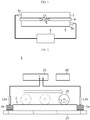
- a conventional electrode assembly defect determining method there is a method of measuring a leakage current amount flowing through an electrode assembly by applying a high voltage to a positive electrode and a negative electrode using a Hi-pot test device 6.
- a separator 4 between a positive electrode plate 3 and a negative electrode plate 5 when a voltage is applied, if a separator 4 between a positive electrode plate 3 and a negative electrode plate 5 is damaged (torn or folded), an arc may be generated at the damage portion (an air layer) and a leakage current may be detected. At this time, if the leakage current exceeds a normal range, the separator is determined as being damaged and thus defective. If abnormality of the separator is detected before the process of packaging the electrode assembly in the battery case or the process of activating after the electrode assembly is packaged, the loss caused by an additional process may be reduced.
- the detection reliability may be deteriorated even though a proper voltage is applied because the pressure applied to cell unit areas varies depending on the flatness of the pressure plate or the like.
- the separator damage detecting device or method merely determines whether the separator is damaged or not.
- the present disclosure is designed to solve the problems of the related art, and therefore the present disclosure is directed to providing a separator damage detecting apparatus, which may enhance separator defect detecting ability with a low voltage in comparison to the conventional art and identify a damage position along with the presence of a separator damage, and a separator damage detecting method using the apparatus.
- a separator damage detecting apparatus which detects a separator damage of a secondary battery by applying a voltage while pressing an electrode assembly having a structure in which a positive electrode plate, a separator and a negative electrode plate are stacked, to induce a temporary short circuit of a positive electrode plate and a negative electrode plate
- the separator damage detecting apparatus comprising: a short circuit measuring unit configured to apply a voltage to the electrode assembly and detect a leakage current; and a pressing jig configured to roll-press at least one surface of the electrode assembly or consecutively press predetermined regions of the at least one surface of the electrode assembly.
- the pressing jig may include a first roller configured to roll-press the at least one surface of the electrode assembly with a uniform pressure from one edge of the electrode assembly to another edge opposite thereto in a horizontal direction.
- the pressing jig may further include a second roller configured to roll-press the at least one surface of the electrode assembly in a direction intersecting with the rolling direction of the first roller.
- the separator damage detecting apparatus may further comprise a defect position calculating unit configured to calculate a separator damage position based on moving speeds of the first roller and the second roller when the first roller and the second roller perform roll-pressing and a leakage current detection time detected by the short circuit measuring unit.
- a defect position calculating unit configured to calculate a separator damage position based on moving speeds of the first roller and the second roller when the first roller and the second roller perform roll-pressing and a leakage current detection time detected by the short circuit measuring unit.
- the pressing jig may include a plurality of partial pressing plates configured to independently press different regions of the at least one surface of the electrode assembly in a direction orthogonal to the one surface of the electrode assembly, and the plurality of partial pressing plates may consecutively or selectively press both edge regions and a central region of the electrode assembly.
- the plurality of partial pressing plates may include edge pressing plates corresponding to both edge regions of the electrode assembly and a center pressing plate corresponding to the central region of the electrode assembly.
- the edge pressing plates may include a first edge pressing plate corresponding to a central portion in the edge region of the electrode assembly; and a second edge pressing plate corresponding to a corner portion in the edge region of the electrode assembly.
- a method for detecting a separator damage of a secondary battery comprising: (a) preparing an electrode assembly having a structure in which a positive electrode plate, a separator and a negative electrode plate are stacked; (b) connecting a short circuit measuring unit to the electrode assembly; and (c) applying a preset voltage to the electrode assembly and detecting a leakage current while pressing at least one surface of the electrode assembly, wherein in the step (c), the at least one surface of the electrode assembly is roll-pressed using a roll, or predesignated regions of the at least one surface of the electrode assembly are consecutively or selectively pressed.
- the electrode assembly may be roll-pressed two times, one in each of horizontal and vertical directions, with a uniform pressure from one edge of the electrode assembly to another edge opposite thereto.
- the method for detecting a separator damage of a secondary battery may further comprise (d) calculating a separator damage position based on a moving speed of the roller and a leakage current detection time detected by the short circuit measuring unit, when the electrode assembly is roll-pressed two times.
- the pressure applied per unit cell area is uniformly increased by roll-pressing or partial pressing instead of the conventional surface pressing, it is possible to improve separator defect detection ability even with a low voltage.
- a separator damage detecting apparatus 1 may be used for detecting a damage of a separator in a full cell having a structure of a positive electrode, a separator and a negative electrode of a unit size, a bi-cell having a structure of a positive electrode, a separator, a negative electrode, a separator and a positive electrode, or an electrode assembly 2 configured by repeatedly stacking full cells or bi-cells.
- the separator damage detecting apparatus 1 according to the present disclosure is directed to detecting a defect of the electrode assembly 2 during a process of assembling a pouch-type secondary battery.
- the separator damage detecting apparatus 1 may be utilized to inspect a separator damage of a secondary battery after the assembling process, for example before/after a formation process or before/after an aging process.
- FIG. 2 is a diagram showing a separator damage detecting apparatus 1 according to an embodiment of the present disclosure.
- the separator damage detecting apparatus 1 includes a short circuit measuring unit 10 for applying a preset voltage to the electrode assembly 2 and detecting a leakage current, a pressing jig 20 for roll-pressing the electrode assembly 2, and a defect position calculating unit 30.
- the short circuit measuring unit 10 is a component for applying a constant voltage to an insulating material and measuring a leakage current or an insulation resistance to determine whether the insulating material is insulated.
- an insulation resistance meter or a Hi-Pot test device may be employed as the short circuit measuring unit 10.
- the short circuit measuring unit 10 is connected to the electrode assembly 2 by contacting a +pin 12a with a positive electrode tab 3a of a positive electrode plate and contacting a -pin 12b with a negative electrode tab 5a of a negative electrode plate before the pressing jig 20 is used.
- the insulating material maintains its insulation up to a certain voltage, but when the voltage increases further, the insulating material loses its insulation and causes dielectric breakdown. At this time, the voltage of the insulating material is called a dielectric breakdown voltage.
- gas has a lower dielectric breakdown voltage than solid.
- a separator damage portion (an air layer) at which the positive electrode plate and the negative electrode plate directly face each other with the air layer being interposed therebetween due to tearing or perforation of the separator has a lower dielectric breakdown voltage than normal portions. In other words, particularly, the risk of short circuit of the positive electrode plate and the negative electrode plate is high at the separator damage portion.
- the separator damage detecting apparatus 1 is configured to increase the detecting ability for a defect separator while reducing the risk during the separator inspection process. Namely, the separator damage detecting apparatus 1 presses the electrode assembly 2 in a roll-pressing manner to induce a temporary short circuit between the positive electrode plate and the negative electrode plate at the separator damage portion D so that the separator damage D may be detected even though a low voltage is applied.
- the electrode assembly 2 is roll-pressed using the pressing jig 20 to make the distances among the positive electrode plate, the separator and the negative electrode plate as small as possible sequentially along the rolling direction, and in this state, a low voltage is applied to determine a defect separator based on whether there is a short circuit between the positive electrode plate and the negative electrode plate.
- a cylindrical roller may be employed as the pressing jig 20.
- the roller-type pressing jig 20 may press a site in contact with an upper surface and/or a lower surface of the electrode assembly 2 while rolling.
- the pressure applied to a unit cell area may be increased with the same force compared to the conventional jig using a surface pressing method, which is more advantageous in causing a temporary short circuit of the separator damage portion.
- FIGS. 3 and 4 are diagrams for illustrating a roll-pressing method using a roller according to an embodiment of the present disclosure.
- the pressing jig 20 includes a first roller 21 and a second roller 22.
- the first roller 21 has a length corresponding to the width of the electrode assembly 2, and the second roller 22 has a length corresponding to the length of the electrode assembly 2.
- the first roller 21 and the second roller 22 may be provided to roll-press the entire area of one surface of the electrode assembly 2 in the horizontal or vertical direction.
- the first roller 21 is provided to roll-press the upper surface of the electrode assembly 2 with a preset pressure from one edge of the electrode assembly 2 to another edge opposite thereto in the horizontal direction.
- the lower surface of the electrode assembly 2 is placed on a worktable 23 of a surface plate, and the electrode assembly 2 is roll-pressed using one first roller 21.
- the upper surface and the lower surface of the electrode assembly 2 may also be roll-pressed using two first rollers 21 simultaneously.
- the first roller 21 performs roll-pressing as above, the positive electrode plate, the separator and the negative electrode plate of the electrode assembly 2 are compressed so that the distances among are consecutively decreased along the rolling direction of the first roller 21.
- the first roller 21 rolls on the damaged position D of the separator in a state where the preset voltage is applied, a short circuit between the positive electrode plate and the negative electrode plate is easily induced at the corresponding position to detect the leakage current.
- the insulation of the separator is maintained as it is since a low voltage is applied, and thus a leakage current is not detected.
- the separator damage detecting apparatus 1 may further include a second roller 22 to increase the reliability of the separator inspection and more accurately identify the separator damage position D.
- the second roller 22 is provided to roll-press the upper surface of the electrode assembly 2 with a preset pressure from one edge of the electrode assembly 2 to another edge opposite thereto in a direction intersecting with the rolling direction of the first roller 21, namely in a vertical direction (+Y-axis direction).
- the detection power may be increased by applying a voltage and roll-pressing the electrode assembly 2 two times by using the first and second rollers 21, 22 to identify a separator damage again. That is, even if a leakage current is not detected during the roll-pressing process by the first roller 21, a leakage current may be detected during the roll-pressing process by the second roller 22. At this time, for the effective inspection, the pressing force of the second roller 22 may be higher than the pressing force of the first roller 21.
- a coordinate of the separator damage position D may be derived by rolling-pressing the electrode assembly 2 with the second roller 22 in a direction intersecting with the first roller 21.
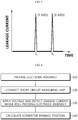
- the moving speeds of the first roller 21 and the second roller 22 may be set in advance, and the time at which the leakage current is detected during the roll-pressing process may also be measured as shown in FIG. 5 .
- the separator damage position may be derived using the following equation based on the moving speeds of the first roller 21 and the second roller 22 and the leakage current detection times.
- the separator damage detecting apparatus 1 may further include a defect position calculating unit 30 for calculating the separator damage position D of at least one site.
- the defect position calculating unit 30 may play a role of receiving the moving speeds of the first and second rollers 21, 22 and the leakage current detection times from the first and second rollers 21, 22 and the short circuit measuring unit 10, calculating the separator damage position D using the above equation, and displaying on a display to be observed by a user.
- the damage position calculating unit 30 may be visually identified quickly and quickly by calculating and displaying the damage position accurately and quickly.
- an electrode assembly 2 serving as an inspection target is loaded on the worktable 23 located in an inspection chamber (S10).
- the +pin 12a and the -pin 12b of the short circuit measuring unit 10 are connected to the positive electrode tab 3a of the positive electrode plate and the negative electrode tab 5a of the negative electrode plate, respectively (S20).
- the +pin 12a and the -pin 12b may electrically contact all of the positive electrode tabs 3a and the negative electrode tabs 5a by integrally pressing the plurality of positive electrode tab 3a and the plurality of negative electrode tab 5a stacked in a rod shape in a vertical direction.
- the separator of the corresponding electrode assembly 2 is determined as a good separator, and if a leakage current over a certain value is detected, the separator of the electrode assembly 2 is determined as a defective separator that is damaged (S30).
- the moving speed of the first roller 21 and the leakage current detection time may be stored in the defect position calculating unit 30.
- the separator damage may be further inspected using the second roller 22 in a case where the separator is determined as being defective in the first inspection and it is intended to correctly determine a damage position of the separator, where there is an error in the inspection due to an insufficient roll-pressing force of the first roller 21 even if the separator is determined as being good in the first inspection, or where additional inspection is required due to any reason.
- the second inspection using the second roller 22 may be omitted.
- the second roller 22 is used to roll-press the upper surface of the electrode assembly 2 in the vertical direction. At this time, the moving speed of the second roller 22 and the leakage current detection time according to the roll-pressing of the second roller 22 are stored in the defect position calculating unit 30.
- the number and positions of damaged separator sites may be calculated based on the moving speeds of the first roller 21 and the second roller 22 and the leakage current detection time by the defect position calculating unit 30 and displayed on the display (not shown) (S40).
- the separator damage position may be calculated accurately using the moving speed of the roller and the leakage current detection time in detecting a separator defect.
- the damage frequency of the separator is observed high in an edge or corner region, it is possible to estimate that there is a problem at a gripper (not shown) used to fold the bi-cell and repair or replace the gripper.
- the gripper holes the edge of the bi-cell and folds the bi-cell, and the stress of the gripper or foreign matters separated from the gripper is likely to cause separator tearing or damage.
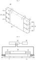
- FIG. 7 is a perspective view schematically showing a pressing jig 20 according to another embodiment of the present disclosure
- FIGS. 8 and 9 are diagrams for illustrating a separator damage detecting process using the pressing jig 20 of FIG. 7 .
- separator damage detecting apparatus 1 according to another embodiment of the present disclosure will be described with reference to these figures.
- the same member number as in the former embodiment denotes the same component, and the same component will not be described in detail, while features different from the former embodiment will be described in detail.
- the pressing jig 20 is provided to consecutively press predesignated regions of at least one surface of the electrode assembly 2. That is, the pressing jig 20 of the former embodiment includes a roller for roll-pressing the electrode assembly 2, whereas the pressing jig 20 of this embodiment may include a plurality of partial pressing plates 25, 26, which are separated per region and independently driven, as shown in FIG. 7 .
- the +pin 13a and the -pin 13b of the short circuit measuring unit 10 may be replaced into a pincers type for stable contact with the plurality of electrode tabs.
- the plurality of partial pressing plates 25, 26 operate to consecutively or selectively press different regions of at least one surface of electrode assembly 2, for example both edge regions and a central region of the electrode assembly 2, in a direction orthogonal to one surface of electrode assembly 2.
- the plurality of partial pressing plates 25, 26 may include edge pressing plates 25 corresponding to both edge regions of the electrode assembly 2 and a center pressing plate 26 corresponding to the central region of the electrode assembly 2.
- the edge pressing plates 25 may include a first edge pressing plate 25a corresponding to a center portion of the separator edge, and second edge pressing plates 25b, 25c corresponding to corner portions of the separator edge.
- the edge pressing plates 25 may partially press the edges and the corner areas of the electrode assembly 2 when inspecting for a separator damage, and the center pressing plate 26 may partially press the broad center region of the electrode assembly 2 independently from the edge pressing plates 25.
- the pressing jig 20 of this embodiment for example, as shown in FIG. 8 , if a leakage current is detected in a state where a voltage is applied and the edge pressing plates 25 are operated, it is possible to determine the occurrence of a separator damage and its damage position at the same time.
- the first inspection may be performed by pressing the edge regions of the electrode assembly 2 by the edge pressing plates 25 and applying a voltage. If there is no problem after the first inspection, as in FIG. 9 , the second inspection may be performed by releasing the pressure to the electrode assembly 2 by the edge pressing plates 25 and operating the center pressing plate 26 to press the center region of the electrode assembly 2 and applying a voltage.
- the edge pressing plate 25 may also be configured such that the first edge pressing plate 25a and the second edge pressing plate 25b, 25c are driven separately, which allows the separator damage position to be identified more accurately at the edge portions of the separator.
- the pressure applied to each unit cell area may be increased with the same driving force as compared to the conventional technique using one pressing plate corresponding to the entire area of the cell. Thus, it may be easier to induce a temporary short circuit of the separator damage portion.
- the defect position calculating unit 30 may be configured to receive the selective operation information of the plurality of partial pressing plates 25, 26 and the leakage current occurrence information from the short circuit measuring unit 10 and the pressing jig 20 and display the separator damage position corresponding to the partial pressing plates 25, 26 used for detecting the leakage current on the display.
Landscapes
- Engineering & Computer Science (AREA)
- Manufacturing & Machinery (AREA)
- Chemical & Material Sciences (AREA)
- Chemical Kinetics & Catalysis (AREA)
- Electrochemistry (AREA)
- General Chemical & Material Sciences (AREA)
- Physics & Mathematics (AREA)
- General Physics & Mathematics (AREA)
- Secondary Cells (AREA)
- Cell Separators (AREA)
Abstract
Description
- The present disclosure relates to a battery separator damage detecting apparatus and method, and more particularly, to a separator damage detecting apparatus capable of detecting a separator damage and a damage position by temporarily inducing a short circuit between electrodes in a pressing manner and applying a voltage, and a separator damage detecting method using the apparatus.
- The present application claims priority to Korean Patent Application No.
10-2018-0093225 filed on August 9, 2018 - Recently, the demand for secondary batteries is rapidly increasing as an environmentally friendly energy source. Among the secondary batteries, lithium secondary batteries exhibiting high energy density and operating potential, long cycle life and low self-discharge rate are being widely commercially used.
- The lithium secondary battery includes an electrode assembly in which a positive electrode plate and a negative electrode plate respectively coated with a positive electrode active material and a negative electrode active material are disposed with a separator being interposed therebetween, and an exterior, namely a battery case, for sealing and accommodating the electrode assembly together with an electrolyte.
- The electrode assembly having a structure including a positive electrode, a separator and a negative electrode structure, which is employed at the lithium secondary battery, may be briefly classified into a jelly-roll type (a rolled type), a stack type (a stacked type), and a stack/fold type that is a combination thereof, depending on the structure.
- The jelly-roll type electrode assembly is prepared by coating a metal foil used as a current collector with an electrode active material or the like, drying and pressing the metal foil, then cutting the metal foil into a band form of a desired width and length, separating a negative electrode and a positive electrode using a separator, and then rolling them into a spiral shape. The jelly-roll type electrode assembly is suitable for cylindrical cells. The stack type electrode assembly has a structure in which a plurality of positive electrode units and negative electrode units are stacked in order, and it is easy to obtain a rectangular shape. The stack/fold type electrode assembly is prepared by folding a full cell having a structure of a positive electrode, a separator and a negative electrode of a unit size or a bi-cell having a structure of a positive electrode, a separator, a negative electrode, a separator and a positive electrode by using a continuous separator film of a long length.
- The electrode assembly prepared as above is sealed and accommodated in the exterior together with the electrolyte after undergoing a defect inspection process. As an example of a conventional electrode assembly defect determining method, there is a method of measuring a leakage current amount flowing through an electrode assembly by applying a high voltage to a positive electrode and a negative electrode using a Hi-
pot test device 6. - For example, as shown in
FIG. 1 , when a voltage is applied, if aseparator 4 between apositive electrode plate 3 and anegative electrode plate 5 is damaged (torn or folded), an arc may be generated at the damage portion (an air layer) and a leakage current may be detected. At this time, if the leakage current exceeds a normal range, the separator is determined as being damaged and thus defective. If abnormality of the separator is detected before the process of packaging the electrode assembly in the battery case or the process of activating after the electrode assembly is packaged, the loss caused by an additional process may be reduced. - Meanwhile, when checking a separator damage, since a dielectric breakdown voltage is theoretically higher than a gas dielectric breakdown voltage, a voltage lower than the dielectric breakdown voltage of the separator is applied. However, if too low voltage is applied, the separator defect detection ability is deteriorated. Also, if a voltage higher than a proper level is applied, a normal separator portion suffers from dielectric breakdown, which may determine a good product as being defective. As a countermeasure, it is possible to induce a temporary short circuit of the positive electrode plate and the negative electrode plate by lowering the voltage and pressing the electrode assembly using a plate-shaped pressing plate so that the distance between the positive electrode plate and the negative electrode plate becomes as small as possible.
- However, in the conventional method of applying the electrode assembly and simultaneously applying a surface pressure to the electrode assembly, the detection reliability may be deteriorated even though a proper voltage is applied because the pressure applied to cell unit areas varies depending on the flatness of the pressure plate or the like.
- In addition, when detecting the separator defect, if the position of the separator damage portion is known, the position of the separator may be utilized as useful data for identifying the cause of the defect and improving the defect later. However, the separator damage detecting device or method merely determines whether the separator is damaged or not.
- The present disclosure is designed to solve the problems of the related art, and therefore the present disclosure is directed to providing a separator damage detecting apparatus, which may enhance separator defect detecting ability with a low voltage in comparison to the conventional art and identify a damage position along with the presence of a separator damage, and a separator damage detecting method using the apparatus.
- However, the technical problem to be solved by the present disclosure is not limited to the above-described problem, and other problems not mentioned herein will be clearly understood by those skilled in the art from the following description.
- In one aspect of the present disclosure, there is provided a separator damage detecting apparatus, which detects a separator damage of a secondary battery by applying a voltage while pressing an electrode assembly having a structure in which a positive electrode plate, a separator and a negative electrode plate are stacked, to induce a temporary short circuit of a positive electrode plate and a negative electrode plate, the separator damage detecting apparatus comprising: a short circuit measuring unit configured to apply a voltage to the electrode assembly and detect a leakage current; and a pressing jig configured to roll-press at least one surface of the electrode assembly or consecutively press predetermined regions of the at least one surface of the electrode assembly.
- The pressing jig may include a first roller configured to roll-press the at least one surface of the electrode assembly with a uniform pressure from one edge of the electrode assembly to another edge opposite thereto in a horizontal direction.
- The pressing jig may further include a second roller configured to roll-press the at least one surface of the electrode assembly in a direction intersecting with the rolling direction of the first roller.
- The separator damage detecting apparatus may further comprise a defect position calculating unit configured to calculate a separator damage position based on moving speeds of the first roller and the second roller when the first roller and the second roller perform roll-pressing and a leakage current detection time detected by the short circuit measuring unit.
- The pressing jig may include a plurality of partial pressing plates configured to independently press different regions of the at least one surface of the electrode assembly in a direction orthogonal to the one surface of the electrode assembly, and the plurality of partial pressing plates may consecutively or selectively press both edge regions and a central region of the electrode assembly.
- The plurality of partial pressing plates may include edge pressing plates corresponding to both edge regions of the electrode assembly and a center pressing plate corresponding to the central region of the electrode assembly.
- The edge pressing plates may include a first edge pressing plate corresponding to a central portion in the edge region of the electrode assembly; and a second edge pressing plate corresponding to a corner portion in the edge region of the electrode assembly.
- In another aspect of the present disclosure, there is also provided a method for detecting a separator damage of a secondary battery, comprising: (a) preparing an electrode assembly having a structure in which a positive electrode plate, a separator and a negative electrode plate are stacked; (b) connecting a short circuit measuring unit to the electrode assembly; and (c) applying a preset voltage to the electrode assembly and detecting a leakage current while pressing at least one surface of the electrode assembly, wherein in the step (c), the at least one surface of the electrode assembly is roll-pressed using a roll, or predesignated regions of the at least one surface of the electrode assembly are consecutively or selectively pressed.
- In the step (c), the electrode assembly may be roll-pressed two times, one in each of horizontal and vertical directions, with a uniform pressure from one edge of the electrode assembly to another edge opposite thereto.
- The method for detecting a separator damage of a secondary battery may further comprise (d) calculating a separator damage position based on a moving speed of the roller and a leakage current detection time detected by the short circuit measuring unit, when the electrode assembly is roll-pressed two times.
- According to an embodiment of the present disclosure, the pressure applied per unit cell area is uniformly increased by roll-pressing or partial pressing instead of the conventional surface pressing, it is possible to improve separator defect detection ability even with a low voltage.
- In addition, since a separator damage position is detected using the moving speed of the roller and the separator defect detection time, it is possible to contribute to eliminating the separator defect cause later.
- The accompanying drawings illustrate a preferred embodiment of the present disclosure and together with the foregoing disclosure, serve to provide further understanding of the technical features of the present disclosure, and thus, the present disclosure is not construed as being limited to the drawing.
-
FIG. 1 is a diagram for illustrating a conventional separator defect detecting method. -
FIG. 2 is a diagram showing a separator damage detecting apparatus according to an embodiment of the present disclosure. -
FIGS. 3 and 4 are diagrams for illustrating a roll-pressing method using a roller according to an embodiment of the present disclosure. -
FIG. 5 is a graph exemplarily showing a leakage current according to moving time of a first roller and a second roller ofFIGS. 3 and 4 . -
FIG. 6 is a flowchart for illustrating processes for performing a separator damage detecting method according to an embodiment of the present disclosure. -
FIG. 7 is a perspective view schematically showing a pressing jig according to another embodiment of the present disclosure. -
FIGS. 8 and9 are diagrams for illustrating a separator damage detecting process using the pressing jig ofFIG. 7 . - Hereinafter, preferred embodiments of the present disclosure will be described in detail with reference to the accompanying drawings. Prior to the description, it should be understood that the terms used in the specification and the appended claims should not be construed as limited to general and dictionary meanings, but interpreted based on the meanings and concepts corresponding to technical aspects of the present disclosure on the basis of the principle that the inventor is allowed to define terms appropriately for the best explanation.
- Therefore, the description proposed herein is just a preferable example for the purpose of illustrations only, not intended to limit the scope of the disclosure, so it should be understood that other equivalents and modifications could be made thereto without departing from the scope of the disclosure.
- A separator
damage detecting apparatus 1 according to the present disclosure described later may be used for detecting a damage of a separator in a full cell having a structure of a positive electrode, a separator and a negative electrode of a unit size, a bi-cell having a structure of a positive electrode, a separator, a negative electrode, a separator and a positive electrode, or anelectrode assembly 2 configured by repeatedly stacking full cells or bi-cells. Namely, the separator damage detectingapparatus 1 according to the present disclosure is directed to detecting a defect of theelectrode assembly 2 during a process of assembling a pouch-type secondary battery. - However, the scope of the present disclosure is not necessarily limited thereto. The separator
damage detecting apparatus 1 may be utilized to inspect a separator damage of a secondary battery after the assembling process, for example before/after a formation process or before/after an aging process. -
FIG. 2 is a diagram showing a separatordamage detecting apparatus 1 according to an embodiment of the present disclosure. - Referring to
FIG. 2 , the separator damage detectingapparatus 1 includes a shortcircuit measuring unit 10 for applying a preset voltage to theelectrode assembly 2 and detecting a leakage current, apressing jig 20 for roll-pressing theelectrode assembly 2, and a defectposition calculating unit 30. - The short
circuit measuring unit 10 is a component for applying a constant voltage to an insulating material and measuring a leakage current or an insulation resistance to determine whether the insulating material is insulated. As the shortcircuit measuring unit 10, an insulation resistance meter or a Hi-Pot test device may be employed. - The short
circuit measuring unit 10 is connected to theelectrode assembly 2 by contacting a +pin 12a with apositive electrode tab 3a of a positive electrode plate and contacting a -pin 12b with anegative electrode tab 5a of a negative electrode plate before thepressing jig 20 is used. - The insulating material maintains its insulation up to a certain voltage, but when the voltage increases further, the insulating material loses its insulation and causes dielectric breakdown. At this time, the voltage of the insulating material is called a dielectric breakdown voltage. In general, gas has a lower dielectric breakdown voltage than solid.
- Thus, a separator damage portion (an air layer) at which the positive electrode plate and the negative electrode plate directly face each other with the air layer being interposed therebetween due to tearing or perforation of the separator has a lower dielectric breakdown voltage than normal portions. In other words, particularly, the risk of short circuit of the positive electrode plate and the negative electrode plate is high at the separator damage portion.
- In consideration of this, the separator
damage detecting apparatus 1 according to an embodiment of the present disclosure is configured to increase the detecting ability for a defect separator while reducing the risk during the separator inspection process. Namely, the separatordamage detecting apparatus 1 presses theelectrode assembly 2 in a roll-pressing manner to induce a temporary short circuit between the positive electrode plate and the negative electrode plate at the separator damage portion D so that the separator damage D may be detected even though a low voltage is applied. - For example, as shown in
FIG. 2 , theelectrode assembly 2 is roll-pressed using thepressing jig 20 to make the distances among the positive electrode plate, the separator and the negative electrode plate as small as possible sequentially along the rolling direction, and in this state, a low voltage is applied to determine a defect separator based on whether there is a short circuit between the positive electrode plate and the negative electrode plate. - As the
pressing jig 20, a cylindrical roller may be employed. The roller-type pressing jig 20 may press a site in contact with an upper surface and/or a lower surface of theelectrode assembly 2 while rolling. Thus, the pressure applied to a unit cell area may be increased with the same force compared to the conventional jig using a surface pressing method, which is more advantageous in causing a temporary short circuit of the separator damage portion. -
FIGS. 3 and 4 are diagrams for illustrating a roll-pressing method using a roller according to an embodiment of the present disclosure. - More specifically, referring to
FIGS. 3 and 4 , the pressingjig 20 according to an embodiment of the present disclosure includes afirst roller 21 and asecond roller 22. - The
first roller 21 has a length corresponding to the width of theelectrode assembly 2, and thesecond roller 22 has a length corresponding to the length of theelectrode assembly 2. Thus, thefirst roller 21 and thesecond roller 22 may be provided to roll-press the entire area of one surface of theelectrode assembly 2 in the horizontal or vertical direction. - For example, as shown in
FIG. 3 , thefirst roller 21 is provided to roll-press the upper surface of theelectrode assembly 2 with a preset pressure from one edge of theelectrode assembly 2 to another edge opposite thereto in the horizontal direction. In this embodiment, the lower surface of theelectrode assembly 2 is placed on aworktable 23 of a surface plate, and theelectrode assembly 2 is roll-pressed using onefirst roller 21. However, in a modified embodiment, the upper surface and the lower surface of theelectrode assembly 2 may also be roll-pressed using twofirst rollers 21 simultaneously. - Since the
first roller 21 performs roll-pressing as above, the positive electrode plate, the separator and the negative electrode plate of theelectrode assembly 2 are compressed so that the distances among are consecutively decreased along the rolling direction of thefirst roller 21. Thus, when thefirst roller 21 rolls on the damaged position D of the separator in a state where the preset voltage is applied, a short circuit between the positive electrode plate and the negative electrode plate is easily induced at the corresponding position to detect the leakage current. Here, when thefirst roller 21 rolls on a portion without a separator damage, the insulation of the separator is maintained as it is since a low voltage is applied, and thus a leakage current is not detected. - Meanwhile, the separator
damage detecting apparatus 1 according to the present disclosure may further include asecond roller 22 to increase the reliability of the separator inspection and more accurately identify the separator damage position D. - As shown in
FIG. 4 , thesecond roller 22 is provided to roll-press the upper surface of theelectrode assembly 2 with a preset pressure from one edge of theelectrode assembly 2 to another edge opposite thereto in a direction intersecting with the rolling direction of thefirst roller 21, namely in a vertical direction (+Y-axis direction). - In this way, the detection power may be increased by applying a voltage and roll-pressing the
electrode assembly 2 two times by using the first andsecond rollers first roller 21, a leakage current may be detected during the roll-pressing process by thesecond roller 22. At this time, for the effective inspection, the pressing force of thesecond roller 22 may be higher than the pressing force of thefirst roller 21. - In particular, according to an embodiment of the present disclosure, a coordinate of the separator damage position D may be derived by rolling-pressing the
electrode assembly 2 with thesecond roller 22 in a direction intersecting with thefirst roller 21. - In other words, the moving speeds of the
first roller 21 and thesecond roller 22 may be set in advance, and the time at which the leakage current is detected during the roll-pressing process may also be measured as shown inFIG. 5 . Thus, the separator damage position may be derived using the following equation based on the moving speeds of thefirst roller 21 and thesecond roller 22 and the leakage current detection times. - 1: X-axis coordinate of the separator damage: Xn = V1×T2
- 2: Y-axis coordinate of the separator damage: Yn = V2×T1
- In addition, the separator
damage detecting apparatus 1 according to the present disclosure may further include a defectposition calculating unit 30 for calculating the separator damage position D of at least one site. - The defect
position calculating unit 30 may play a role of receiving the moving speeds of the first andsecond rollers second rollers circuit measuring unit 10, calculating the separator damage position D using the above equation, and displaying on a display to be observed by a user. - If the defect
position calculating unit 30 is used, even though the information value is increased due to a lot of separator damages, the damage position may be visually identified quickly and quickly by calculating and displaying the damage position accurately and quickly. - Hereinafter, a separator damage detecting method will be described in brief with reference to
FIG. 6 along withFIGS. 2 to 5 . - First, an
electrode assembly 2 serving as an inspection target is loaded on theworktable 23 located in an inspection chamber (S10). - After that, the +
pin 12a and the -pin 12b of the shortcircuit measuring unit 10 are connected to thepositive electrode tab 3a of the positive electrode plate and thenegative electrode tab 5a of the negative electrode plate, respectively (S20). At this time, as shown inFIG. 2 , the +pin 12a and the -pin 12b may electrically contact all of thepositive electrode tabs 3a and thenegative electrode tabs 5a by integrally pressing the plurality ofpositive electrode tab 3a and the plurality ofnegative electrode tab 5a stacked in a rod shape in a vertical direction. - After that, a preset voltage is applied, and the upper surface of the
electrode assembly 2 is roll-pressed in a horizontal direction by using thefirst roller 21. If no leakage current over a certain value is detected during the roll-pressing process by thefirst roller 21, the separator of the correspondingelectrode assembly 2 is determined as a good separator, and if a leakage current over a certain value is detected, the separator of theelectrode assembly 2 is determined as a defective separator that is damaged (S30). In addition, when determining a separator defect, the moving speed of thefirst roller 21 and the leakage current detection time may be stored in the defectposition calculating unit 30. - After that, the separator damage may be further inspected using the
second roller 22 in a case where the separator is determined as being defective in the first inspection and it is intended to correctly determine a damage position of the separator, where there is an error in the inspection due to an insufficient roll-pressing force of thefirst roller 21 even if the separator is determined as being good in the first inspection, or where additional inspection is required due to any reason. Thus, if the separator is determined as being good in the first inspection and there is no special reason for additional inspection, the second inspection using thesecond roller 22 may be omitted. - However, if it is necessary to accurately identify the separator damage position as described above, the
second roller 22 is used to roll-press the upper surface of theelectrode assembly 2 in the vertical direction. At this time, the moving speed of thesecond roller 22 and the leakage current detection time according to the roll-pressing of thesecond roller 22 are stored in the defectposition calculating unit 30. - After that, the number and positions of damaged separator sites may be calculated based on the moving speeds of the
first roller 21 and thesecond roller 22 and the leakage current detection time by the defectposition calculating unit 30 and displayed on the display (not shown) (S40). - According to this embodiment having the configuration and operation as described above, it is possible to induce a temporary short circuit of the separator damage portion just at a low voltage and effectively detect a separator damage by uniformly increasing the pressure applied to each unit cell area with the same pressing force compared to the conventional jig using a surface pressing method Further, the separator damage position may be calculated accurately using the moving speed of the roller and the leakage current detection time in detecting a separator defect.
- If the frequency of separator damage positions is identified as above, it is possible to estimate a process and a cause by which the separator is damaged, and the cause of the defect may be eliminated by effectively improving the process and cause.
- For example, if the damage frequency of the separator is observed high in an edge or corner region, it is possible to estimate that there is a problem at a gripper (not shown) used to fold the bi-cell and repair or replace the gripper. For a folding work, the gripper holes the edge of the bi-cell and folds the bi-cell, and the stress of the gripper or foreign matters separated from the gripper is likely to cause separator tearing or damage.
-
FIG. 7 is a perspective view schematically showing apressing jig 20 according to another embodiment of the present disclosure, andFIGS. 8 and9 are diagrams for illustrating a separator damage detecting process using thepressing jig 20 ofFIG. 7 . - Hereinafter, a separator
damage detecting apparatus 1 according to another embodiment of the present disclosure will be described with reference to these figures. The same member number as in the former embodiment denotes the same component, and the same component will not be described in detail, while features different from the former embodiment will be described in detail. - The
pressing jig 20 according to this embodiment is provided to consecutively press predesignated regions of at least one surface of theelectrode assembly 2. That is, the pressingjig 20 of the former embodiment includes a roller for roll-pressing theelectrode assembly 2, whereas thepressing jig 20 of this embodiment may include a plurality of partialpressing plates FIG. 7 . In addition, as in this embodiment, the +pin 13a and the -pin 13b of the shortcircuit measuring unit 10 may be replaced into a pincers type for stable contact with the plurality of electrode tabs. - The plurality of partial
pressing plates electrode assembly 2, for example both edge regions and a central region of theelectrode assembly 2, in a direction orthogonal to one surface ofelectrode assembly 2. - More specifically, the plurality of partial
pressing plates edge pressing plates 25 corresponding to both edge regions of theelectrode assembly 2 and acenter pressing plate 26 corresponding to the central region of theelectrode assembly 2. In addition, theedge pressing plates 25 may include a firstedge pressing plate 25a corresponding to a center portion of the separator edge, and secondedge pressing plates - The
edge pressing plates 25 may partially press the edges and the corner areas of theelectrode assembly 2 when inspecting for a separator damage, and thecenter pressing plate 26 may partially press the broad center region of theelectrode assembly 2 independently from theedge pressing plates 25. - According to the configuration and operation of the
pressing jig 20 of this embodiment, for example, as shown inFIG. 8 , if a leakage current is detected in a state where a voltage is applied and theedge pressing plates 25 are operated, it is possible to determine the occurrence of a separator damage and its damage position at the same time. - Considering that the possibility of separator damage is generally higher at the edge than the center, the first inspection may be performed by pressing the edge regions of the
electrode assembly 2 by theedge pressing plates 25 and applying a voltage. If there is no problem after the first inspection, as inFIG. 9 , the second inspection may be performed by releasing the pressure to theelectrode assembly 2 by theedge pressing plates 25 and operating thecenter pressing plate 26 to press the center region of theelectrode assembly 2 and applying a voltage. - In this embodiment, the
edge pressing plate 25 may also be configured such that the firstedge pressing plate 25a and the secondedge pressing plate - In addition, in this embodiment, since the pressing plates are separated into several pieces, the pressure applied to each unit cell area may be increased with the same driving force as compared to the conventional technique using one pressing plate corresponding to the entire area of the cell. Thus, it may be easier to induce a temporary short circuit of the separator damage portion.
- Meanwhile, in this embodiment, the defect
position calculating unit 30 may be configured to receive the selective operation information of the plurality of partialpressing plates circuit measuring unit 10 and thepressing jig 20 and display the separator damage position corresponding to the partialpressing plates - The present disclosure has been described in detail. However, it should be understood that the detailed description and specific examples, while indicating preferred embodiments of the disclosure, are given by way of illustration only, since various changes and modifications within the scope of the disclosure will become apparent to those skilled in the art from this detailed description.
- Meanwhile, when the terms indicating up, down, left and right directions are used in the specification, it is obvious to those skilled in the art that these merely represent relative locations for convenience in explanation and may vary based on a location of an observer or an object to be observed.
Claims (10)
- A separator damage detecting apparatus, which detects a separator damage of a secondary battery by applying a voltage while pressing an electrode assembly having a structure in which a positive electrode plate, a separator and a negative electrode plate are stacked, to induce a temporary short circuit of a positive electrode plate and a negative electrode plate, the separator damage detecting apparatus comprising:a short circuit measuring unit configured to apply a voltage to the electrode assembly and detect a leakage current; anda pressing jig configured to roll-press at least one surface of the electrode assembly or consecutively press predetermined regions of the at least one surface of the electrode assembly.
- The separator damage detecting apparatus according to claim 1,
wherein the pressing jig includes a first roller configured to roll-press the at least one surface of the electrode assembly with a uniform pressure from one edge of the electrode assembly to another edge opposite thereto in a horizontal direction. - The separator damage detecting apparatus according to claim 2,
wherein the pressing jig further includes a second roller configured to roll-press the at least one surface of the electrode assembly in a direction intersecting with the rolling direction of the first roller. - The separator damage detecting apparatus according to claim 3, further comprising:
a defect position calculating unit configured to calculate a separator damage position based on moving speeds of the first roller and the second roller when the first roller and the second roller perform roll-pressing and a leakage current detection time detected by the short circuit measuring unit. - The separator damage detecting apparatus according to claim 1,
wherein the pressing jig includes a plurality of partial pressing plates configured to independently press different regions of the at least one surface of the electrode assembly in a direction orthogonal to the one surface of the electrode assembly, and the plurality of partial pressing plates consecutively or selectively press both edge regions and a central region of the electrode assembly. - The separator damage detecting apparatus according to claim 5,
wherein the plurality of partial pressing plates include edge pressing plates corresponding to both edge regions of the electrode assembly and a center pressing plate corresponding to the central region of the electrode assembly. - The separator damage detecting apparatus according to claim 6,
wherein the edge pressing plates include:a first edge pressing plate corresponding to a central portion in the edge region of the electrode assembly; anda second edge pressing plate corresponding to a corner portion in the edge region of the electrode assembly. - A method for detecting a separator damage of a secondary battery, comprising:(a) preparing an electrode assembly having a structure in which a positive electrode plate, a separator and a negative electrode plate are stacked;(b) connecting a short circuit measuring unit to the electrode assembly; and(c) applying a preset voltage to the electrode assembly and detecting a leakage current while pressing at least one surface of the electrode assembly,wherein in the step (c), the at least one surface of the electrode assembly is roll-pressed using a roll, or predesignated regions of the at least one surface of the electrode assembly are consecutively or selectively pressed.
- The method for detecting a separator damage of a secondary battery according to claim 8,
wherein in the step (c), the electrode assembly is roll-pressed two times, one in each of horizontal and vertical directions, with a uniform pressure from one edge of the electrode assembly to another edge opposite thereto. - The method for detecting a separator damage of a secondary battery according to claim 9, further comprising:
(d) calculating a separator damage position based on a moving speed of the roller and a leakage current detection time detected by the short circuit measuring unit, when the electrode assembly is roll-pressed two times.
Applications Claiming Priority (2)
| Application Number | Priority Date | Filing Date | Title |
|---|---|---|---|
| KR1020180093225A KR102395248B1 (en) | 2018-08-09 | 2018-08-09 | Apparatus for detecting a defect of battery separator and Detecting method using the same |
| PCT/KR2019/004380 WO2020032343A1 (en) | 2018-08-09 | 2019-04-11 | Method and apparatus for detecting damage of battery separator |
Publications (3)
| Publication Number | Publication Date |
|---|---|
| EP3719915A1 true EP3719915A1 (en) | 2020-10-07 |
| EP3719915A4 EP3719915A4 (en) | 2021-05-05 |
| EP3719915B1 EP3719915B1 (en) | 2026-01-28 |
Family
ID=69414970
Family Applications (1)
| Application Number | Title | Priority Date | Filing Date |
|---|---|---|---|
| EP19848734.0A Active EP3719915B1 (en) | 2018-08-09 | 2019-04-11 | Method and apparatus for detecting damage of battery separator |
Country Status (6)
| Country | Link |
|---|---|
| US (1) | US11287478B2 (en) |
| EP (1) | EP3719915B1 (en) |
| KR (1) | KR102395248B1 (en) |
| CN (1) | CN111357145B (en) |
| ES (1) | ES3064211T3 (en) |
| WO (1) | WO2020032343A1 (en) |
Cited By (1)
| Publication number | Priority date | Publication date | Assignee | Title |
|---|---|---|---|---|
| EP4513616A3 (en) * | 2023-08-21 | 2025-07-09 | SK On Co., Ltd. | Apparatus for checking for short circuits |
Families Citing this family (19)
| Publication number | Priority date | Publication date | Assignee | Title |
|---|---|---|---|---|
| JP7067846B2 (en) * | 2020-03-31 | 2022-05-16 | パナソニックホールディングス株式会社 | Insulation inspection equipment |
| CN111947866A (en) * | 2020-07-22 | 2020-11-17 | 苏州华智诚精工科技有限公司 | Novel battery leakage detection method |
| CN112462218B (en) * | 2020-11-10 | 2023-06-02 | 珠海冠宇电池股份有限公司 | A cell pressurization tool, a cell withstand voltage test device, and a withstand voltage test method |
| CN112881941B (en) * | 2021-01-08 | 2024-09-13 | 东莞市嘉仕新能电子仪器设备有限公司 | Insulation test method capable of detecting cell capillary short circuit and corresponding battery conduction insulation tester |
| CN113093051B (en) * | 2021-03-31 | 2022-09-16 | 蜂巢能源科技股份有限公司 | A method for short-circuit detection of laminated lithium ion batteries and a method for removing battery cells |
| KR102929656B1 (en) | 2021-07-14 | 2026-02-20 | 현대자동차주식회사 | Electrode tab fold judging apparatus and judging method |
| CN113900022A (en) * | 2021-09-13 | 2022-01-07 | 东莞市创明电池技术有限公司 | Method for determining position of short-circuit point of winding core |
| KR102661396B1 (en) * | 2021-11-08 | 2024-04-29 | 주식회사 엘지에너지솔루션 | Roll map producing device for merged electrode |
| CN114217239B (en) * | 2021-11-30 | 2024-11-19 | 风帆有限责任公司 | AGM battery separator damage detection method and detection terminal |
| EP4443596A4 (en) * | 2021-12-03 | 2025-05-07 | LG Energy Solution, Ltd. | TEMPLATE FOR EVALUATING THE SAFETY OF A SECONDARY BATTERY |
| KR20230095312A (en) * | 2021-12-22 | 2023-06-29 | 주식회사 엘지에너지솔루션 | Apparatus for detecting the location of foreign substances in low-voltage battery cells and detecting method using the same |
| CN116699456A (en) * | 2022-02-28 | 2023-09-05 | 宁德时代新能源科技股份有限公司 | Leakage detection method and leakage detection equipment |
| KR20230142917A (en) * | 2022-04-04 | 2023-10-11 | 주식회사 엘지에너지솔루션 | Manufacturing method for electrode assembly and electrode assembly manufacturing equipment |
| KR102868286B1 (en) * | 2022-04-27 | 2025-10-02 | 주식회사 엘지에너지솔루션 | Fault test device and fault test method of secondary battery |
| CN116068024B (en) * | 2022-11-24 | 2023-07-07 | 中国石油大学(华东) | A Membrane Electrode Online Detection System Applied to Roll-to-Roll Production Line |
| KR20240084394A (en) | 2022-12-06 | 2024-06-13 | 주식회사 엘지에너지솔루션 | Method for Detecting Defect of Separator |
| KR20240138261A (en) * | 2023-03-10 | 2024-09-20 | 에스케이온 주식회사 | secondary battery cell insulation test apparatus and method using the same |
| CN220231945U (en) * | 2023-03-30 | 2023-12-22 | 蜂巢能源科技(无锡)有限公司 | Pole piece short circuit test fixture and pole piece production system |
| CN116660787A (en) * | 2023-06-09 | 2023-08-29 | 上海韵量新能源科技有限公司 | Detection method, device, electronic equipment and medium of proton exchange membrane |
Family Cites Families (15)
| Publication number | Priority date | Publication date | Assignee | Title |
|---|---|---|---|---|
| JP3677993B2 (en) | 1998-04-06 | 2005-08-03 | 松下電器産業株式会社 | Battery electrode group short circuit inspection method and short circuit inspection apparatus therefor |
| JP4666712B2 (en) * | 2000-02-22 | 2011-04-06 | パナソニック株式会社 | Battery short-circuit inspection method |
| JP4666897B2 (en) * | 2003-08-25 | 2011-04-06 | パナソニック株式会社 | Battery manufacturing method |
| JP4993196B2 (en) * | 2007-08-23 | 2012-08-08 | トヨタ自動車株式会社 | Method for inspecting wound electrode body and inspection apparatus for wound electrode body |
| JP2009093797A (en) | 2007-10-03 | 2009-04-30 | Dic Corp | Crack detection method for fuel cell separator and crack detection device for fuel cell separator |
| KR100965540B1 (en) | 2008-05-22 | 2010-06-23 | 주식회사 태진정공 | Heat Roller Leakage Current Test Device |
| JP2010032346A (en) | 2008-07-29 | 2010-02-12 | Panasonic Corp | Method of inspecting electrode group for secondary battery |
| JP5137730B2 (en) | 2008-07-31 | 2013-02-06 | 三洋電機株式会社 | Battery separator inspection method and battery inspection method |
| CN102388483B (en) * | 2009-01-12 | 2016-04-06 | A123系统有限责任公司 | Laminate battery and its preparation method |
| KR101179347B1 (en) | 2009-01-19 | 2012-09-04 | 파나소닉 주식회사 | Internal Short Circuit Evaluation Apparatus for Battery |
| CN201611375U (en) * | 2009-12-04 | 2010-10-20 | 天空能源(洛阳)有限公司 | Detection device for lithium-ion power battery dissepiment |
| KR101558250B1 (en) * | 2013-05-23 | 2015-10-07 | 주식회사 엘지화학 | Fixation Device for Checking Defect of Electrode Assembly and Method of Checking the Same |
| KR101800051B1 (en) | 2013-10-31 | 2017-11-21 | 주식회사 엘지화학 | Short measuring apparatus of unit cell |
| KR101790118B1 (en) | 2014-12-05 | 2017-10-25 | 주식회사 엘지화학 | Pressing Device for Checking Defect of Electrode Assembly and Method of Checking the Same |
| KR20180093225A (en) | 2017-02-11 | 2018-08-21 | 권명순 | Brightness-adjustable LED light with vision protection |
-
2018
- 2018-08-09 KR KR1020180093225A patent/KR102395248B1/en active Active
-
2019
- 2019-04-11 US US16/959,198 patent/US11287478B2/en active Active
- 2019-04-11 EP EP19848734.0A patent/EP3719915B1/en active Active
- 2019-04-11 ES ES19848734T patent/ES3064211T3/en active Active
- 2019-04-11 WO PCT/KR2019/004380 patent/WO2020032343A1/en not_active Ceased
- 2019-04-11 CN CN201980005688.3A patent/CN111357145B/en active Active
Cited By (1)
| Publication number | Priority date | Publication date | Assignee | Title |
|---|---|---|---|---|
| EP4513616A3 (en) * | 2023-08-21 | 2025-07-09 | SK On Co., Ltd. | Apparatus for checking for short circuits |
Also Published As
| Publication number | Publication date |
|---|---|
| ES3064211T3 (en) | 2026-04-23 |
| EP3719915A4 (en) | 2021-05-05 |
| KR102395248B1 (en) | 2022-05-04 |
| US20200400747A1 (en) | 2020-12-24 |
| WO2020032343A1 (en) | 2020-02-13 |
| CN111357145A (en) | 2020-06-30 |
| CN111357145B (en) | 2023-08-29 |
| KR20200017824A (en) | 2020-02-19 |
| US11287478B2 (en) | 2022-03-29 |
| EP3719915B1 (en) | 2026-01-28 |
Similar Documents
| Publication | Publication Date | Title |
|---|---|---|
| EP3719915B1 (en) | Method and apparatus for detecting damage of battery separator | |
| KR102509603B1 (en) | Apparatus for detecting a low voltage pouch type secondary battery cell | |
| KR102619196B1 (en) | Apparatus for detecting a low voltage pouch type secondary battery cell | |
| KR102602205B1 (en) | Degas system for secondary cell | |
| KR20200059563A (en) | Method for testing pressure short defect by jig pressing | |
| KR102795945B1 (en) | Defective Inspection Device of Pouch-type Battery Cell | |
| JP2008243439A (en) | Battery abnormality detection device and battery abnormality detection method | |
| US7239147B2 (en) | Method and device for inspecting secondary battery precursor and method for manufacturing secondary battery using the inspection method | |
| CN116710766B (en) | Equipment for detecting foreign object locations in low-voltage battery cells and analytical methods using the equipment | |
| KR20200059483A (en) | Pressure short testing device for detecting a low voltage battery cell | |
| KR20200035594A (en) | Non-destructive method for detecting disconnection of battery cell using pressing force | |
| KR102675556B1 (en) | Rolling module for secondary battery cell | |
| US20240302425A1 (en) | Secondary Battery Cell Insulation Test Apparatus and Method Using the Same | |
| KR102221782B1 (en) | Apparatus for detecting defects | |
| KR102772444B1 (en) | A detecting method of welding defect | |
| JP7733737B2 (en) | Apparatus and method for detecting internal defects in battery cells using TDR | |
| KR20210150106A (en) | Thickness measuring device for sealing portion of secondaty battery and method for measuring thickness using the same | |
| KR102872285B1 (en) | Detectign appratus and method of welding defect | |
| KR102940138B1 (en) | Apparatus for detecting a defect of battery separator including a plurality of pressing rollers and method for detecting a defect of battery separator using same | |
| US20250309384A1 (en) | Battery inspection apparatus and inspection method of the same | |
| KR20260015420A (en) | Inspection apparatus | |
| US20240302437A1 (en) | Secondary Battery Cell Insulation Test Apparatus and Method Using the Same | |
| KR20250162339A (en) | System for inspecting battery and inspecting method of battery | |
| KR20260071581A (en) | Apparatus for checking battery and checking method of battery | |
| KR102307296B1 (en) | Apparatus for detecting defects |
Legal Events
| Date | Code | Title | Description |
|---|---|---|---|
| STAA | Information on the status of an ep patent application or granted ep patent |
Free format text: STATUS: THE INTERNATIONAL PUBLICATION HAS BEEN MADE |
|
| PUAI | Public reference made under article 153(3) epc to a published international application that has entered the european phase |
Free format text: ORIGINAL CODE: 0009012 |
|
| STAA | Information on the status of an ep patent application or granted ep patent |
Free format text: STATUS: REQUEST FOR EXAMINATION WAS MADE |
|
| 17P | Request for examination filed |
Effective date: 20200702 |
|
| AK | Designated contracting states |
Kind code of ref document: A1 Designated state(s): AL AT BE BG CH CY CZ DE DK EE ES FI FR GB GR HR HU IE IS IT LI LT LU LV MC MK MT NL NO PL PT RO RS SE SI SK SM TR |
|
| AX | Request for extension of the european patent |
Extension state: BA ME |
|
| A4 | Supplementary search report drawn up and despatched |
Effective date: 20210401 |
|
| RIC1 | Information provided on ipc code assigned before grant |
Ipc: H01M 10/42 20060101AFI20210326BHEP Ipc: H01M 10/04 20060101ALI20210326BHEP Ipc: G01R 1/04 20060101ALI20210326BHEP Ipc: H01M 10/48 20060101ALI20210326BHEP |
|
| DAV | Request for validation of the european patent (deleted) | ||
| DAX | Request for extension of the european patent (deleted) | ||
| RAP1 | Party data changed (applicant data changed or rights of an application transferred) |
Owner name: LG ENERGY SOLUTION LTD. |
|
| RAP3 | Party data changed (applicant data changed or rights of an application transferred) |
Owner name: LG ENERGY SOLUTION, LTD. |
|
| GRAP | Despatch of communication of intention to grant a patent |
Free format text: ORIGINAL CODE: EPIDOSNIGR1 |
|
| STAA | Information on the status of an ep patent application or granted ep patent |
Free format text: STATUS: GRANT OF PATENT IS INTENDED |
|
| INTG | Intention to grant announced |
Effective date: 20251021 |
|
| GRAS | Grant fee paid |
Free format text: ORIGINAL CODE: EPIDOSNIGR3 |
|
| P01 | Opt-out of the competence of the unified patent court (upc) registered |
Free format text: CASE NUMBER: UPC_APP_0013195_3719915/2025 Effective date: 20251113 |
|
| GRAA | (expected) grant |
Free format text: ORIGINAL CODE: 0009210 |
|
| STAA | Information on the status of an ep patent application or granted ep patent |
Free format text: STATUS: THE PATENT HAS BEEN GRANTED |
|
| AK | Designated contracting states |
Kind code of ref document: B1 Designated state(s): AL AT BE BG CH CY CZ DE DK EE ES FI FR GB GR HR HU IE IS IT LI LT LU LV MC MK MT NL NO PL PT RO RS SE SI SK SM TR |
|
| REG | Reference to a national code |
Ref country code: CH Ref legal event code: F10 Free format text: ST27 STATUS EVENT CODE: U-0-0-F10-F00 (AS PROVIDED BY THE NATIONAL OFFICE) Effective date: 20260128 Ref country code: GB Ref legal event code: FG4D |
|
| REG | Reference to a national code |
Ref country code: DE Ref legal event code: R096 Ref document number: 602019080871 Country of ref document: DE |
|
| REG | Reference to a national code |
Ref country code: IE Ref legal event code: FG4D |
|
| PGFP | Annual fee paid to national office [announced via postgrant information from national office to epo] |
Ref country code: GB Payment date: 20260324 Year of fee payment: 8 |
|
| PGFP | Annual fee paid to national office [announced via postgrant information from national office to epo] |
Ref country code: BE Payment date: 20260323 Year of fee payment: 8 |
|
| PGFP | Annual fee paid to national office [announced via postgrant information from national office to epo] |
Ref country code: FR Payment date: 20260323 Year of fee payment: 8 |
|
| REG | Reference to a national code |
Ref country code: ES Ref legal event code: FG2A Ref document number: 3064211 Country of ref document: ES Kind code of ref document: T3 Effective date: 20260423 |