EP3719635A1 - Methods and apparatus for in-field mitigation of firmware failures - Google Patents
Methods and apparatus for in-field mitigation of firmware failures Download PDFInfo
- Publication number
- EP3719635A1 EP3719635A1 EP20161582.0A EP20161582A EP3719635A1 EP 3719635 A1 EP3719635 A1 EP 3719635A1 EP 20161582 A EP20161582 A EP 20161582A EP 3719635 A1 EP3719635 A1 EP 3719635A1
- Authority
- EP
- European Patent Office
- Prior art keywords
- firmware
- processor
- feature
- mask
- feature mask
- Prior art date
- Legal status (The legal status is an assumption and is not a legal conclusion. Google has not performed a legal analysis and makes no representation as to the accuracy of the status listed.)
- Withdrawn
Links
Images




Classifications
-
- G—PHYSICS
- G06—COMPUTING OR CALCULATING; COUNTING
- G06F—ELECTRIC DIGITAL DATA PROCESSING
- G06F8/00—Arrangements for software engineering
- G06F8/60—Software deployment
- G06F8/65—Updates
-
- G—PHYSICS
- G06—COMPUTING OR CALCULATING; COUNTING
- G06F—ELECTRIC DIGITAL DATA PROCESSING
- G06F11/00—Error detection; Error correction; Monitoring
- G06F11/07—Responding to the occurrence of a fault, e.g. fault tolerance
- G06F11/14—Error detection or correction of the data by redundancy in operations
- G06F11/1402—Saving, restoring, recovering or retrying
- G06F11/1415—Saving, restoring, recovering or retrying at system level
- G06F11/1433—Saving, restoring, recovering or retrying at system level during software upgrading
-
- G—PHYSICS
- G06—COMPUTING OR CALCULATING; COUNTING
- G06F—ELECTRIC DIGITAL DATA PROCESSING
- G06F8/00—Arrangements for software engineering
- G06F8/70—Software maintenance or management
- G06F8/71—Version control; Configuration management
-
- G—PHYSICS
- G06—COMPUTING OR CALCULATING; COUNTING
- G06F—ELECTRIC DIGITAL DATA PROCESSING
- G06F9/00—Arrangements for program control, e.g. control units
- G06F9/06—Arrangements for program control, e.g. control units using stored programs, i.e. using an internal store of processing equipment to receive or retain programs
- G06F9/44—Arrangements for executing specific programs
- G06F9/4401—Bootstrapping
Definitions
- This disclosure relates generally to firmware updates, and, more particularly, to methods and apparatus for in-field mitigation of firmware failures.
- Firmware is a type of computer software that enables control of device hardware. Firmware plays an ever-increasing role in the functionality, performance, and security of a system While firmware is typically developed and deployed (e.g., sold and/or provided) with hardware, in some cases, firmware may be updated to fix issues and/or provide new features. Firmware updates present a challenge to a computing device ecosystem.
- Descriptors "first,” “second,” “third,” etc. are used herein when identifying multiple elements or components which may be referred to separately. Unless otherwise specified or understood based on their context of use, such descriptors are not intended to impute any meaning of priority, physical order or arrangement in a list, or ordering in time but are merely used as labels for referring to multiple elements or components separately for ease of understanding the disclosed examples.
- the descriptor "first” may be used to refer to an element in the detailed description, while the same element may be referred to in a claim with a different descriptor such as "second” or “third.” In such instances, it should be understood that such descriptors are used merely for ease of referencing multiple elements or components.
- firmware vendor an original equipment manufacturer (OEM), and/or other firmware-providing entity provides firmware for use on computing devices.
- firmware is installed on such computing devices at a time of manufacture.
- firmware is provided and/or installed while a device is operating in the field.
- Firmware updates can be provided to, for example, patch security vulnerabilities, provide new features, fix bugs, etc.
- firmware-providing entity it is impractical for a firmware-providing entity to validate all scenarios for their products in the field (e.g., to account for various auxiliary devices that may be connected to the computing device). As a result, firmware deployment failures can occur. Such failures can result in an updated device being inoperable and/or unrecoverable. As a result, a great deal of testing is performed prior to distribution of a firmware update to attempt to ensure that devices do not become inoperable. In some examples, a firmware update and/or distribution thereof is dependent upon other entities (e.g., an OEM for integration and/or distribution). Such dependencies on OEM partners make it difficult to provide firmware updates (which may include critical security fixes) in a timely fashion.
- Examples disclosed herein reduce firmware deployment failures, as well as allow for particular features of a computing device to be enabled and/or disabled to allow for mitigation of security vulnerabilities.
- Example approaches disclosed herein utilize a secure de-feature mechanism that is exposed to firmware-providing entities. This allows mitigation of zero-day exploits with no firmware or software modification by remotely instructing pre-existing firmware provisioned on the computing device to de-feature (e.g., disable) the exploited feature.
- examples disclosed herein utilize automated remediation in the field to perform secure firmware upgrades and/or secure firmware downgrades.
- firmware update does not necessarily need to be a newer version of the firmware than has been previously distributed. That is, the firmware update may represent a roll-back to a prior firmware version (e.g., to mitigate effects of an intermediate firmware update that may present vulnerabilities).
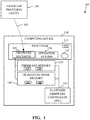
- FIG. 1 is a block diagram of an example environment of use 100 including an example computing device 110 implemented in accordance with the teachings of this disclosure.
- the example environment of use 100 includes a firmware-providing entity 101 that provides 102 a firmware update and/or a de-feature mask to a firmware manager 105 of the computing device 110.
- the example computing device 110 includes a processor 112 that implements the firmware manager 105 and executes firmware 115 provided by a platform firmware controller (PFC) 130.
- the example firmware manager 105 provides the firmware and/or de-feature mask (e.g., the firmware and/or de-feature mask received from the firmware-providing entity 101) to the platform firmware controller 130 via a firmware memory 135 and/or a de-feature mask memory 140.
- the example processor 112 implements an operating system 150 and/or other applications.
- the example firmware-providing entity 101 of the illustrated example of FIG. 1 is implemented by a server that provides firmware updates to the example computing device 110.
- the firmware-providing entity 101 operates at the direction of a computer administrator (e.g., a remote administrator, an information technology personnel, etc.).
- the firmware-providing entity 101 is operated by an operating system vendor and/or an original equipment manufacturer (OEM).
- OEM original equipment manufacturer
- any other party may operate the firmware-providing entity 101.
- the firmware-providing entity 101 provides firmware (e.g., a firmware update) and/or a de-feature mask to the computing device 110 via a network (e.g., the network 626 of FIG. 6 ) such as, for example, the Internet.
- firmware-providing entity 101 may implement a web server.
- firmware and/or de-feature masks may be provided 102 to the computing device 110 in any fashion such as, for example, via a physical computer-readable storage disk or storage device that is physically transported to the computing device (e.g., via postal mail).
- the example computing device 110 of the illustrated example of FIG. 1 may be implemented by any type of computing device.
- the computing device is a desktop computer.
- any other computing device form factor may additionally or alternatively be used such as, for example, a mobile device, a server computer, an embedded computing device, an Internet of Things (IoT) computing device, etc.
- IoT Internet of Things
- the example computing device includes the example processor 112.
- the example processor 112 of the illustrated example of FIG. 1 is implemented by a hardware processor.
- any other circuitry may additionally or alternatively be used such as, for example, analog or digital circuit(s), logic circuits, programmable processor(s), programmable controller(s), graphics processing unit(s) (GPU(s)), digital signal processor(s) (DSP(s)), application specific integrated circuit(s) (ASIC(s)), programmable logic device(s) (PLD(s)), field programmable logic device(s) (FPLD(s)), etc.
- the firmware manager 105 determines that the new de-feature mask is available in response to an indication from the firmware-providing entity 101 that a new de-feature mask is available. In some examples, the firmware manager 105 may periodically and/or a-periodically contact the example firmware-providing entity 101 to determine if a new de-feature mask is available. In some other examples, the firmware-providing entity 101 transmits an unsolicited notification (e.g., a push message) to the firmware manager 105 to alert the firmware manager 105 to the presence of an updated (e.g., new) de-feature mask.
- an unsolicited notification e.g., a push message
- the firmware-providing entity 101 can provide instructions (e.g., a de-feature mask) that disable a feature in the firmware.
- the example firmware manager 105 determines that a new de-feature mask is available, the example firmware manager 105 stores the de-feature mask in the de-feature mask memory 140.
- the de-feature mask is stored in the de-feature mask memory 140 in an authenticated fashion. That is, additional security primitives may be applied to the de-feature mask including confidentiality, integrity, replay protection, etc. to ensure the mask is not visible, modifiable, and/or open to replay attack from other system components.
- the firmware manager 105 stores the de-feature mask in a first location 141 of the de-feature mask memory 140, and a prior de-feature mask in a second location 142 of the de-feature mask memory 140.
- the example firmware manager 105 determines that a new firmware update is available, the example firmware manager 105 stores the firmware update in the firmware memory 135.
- the firmware update is stored in the firmware memory 135 in an authenticated fashion, thereby ensuring that the firmware update is not visible, modifiable, and/or open to replay attack from other system components.
- the firmware manager 105 stores the firmware update a first location 137 of the firmware memory 135, and stores a prior version of the firmware (e.g., a rollback version of the firmware, a recovery version of the firmware) in a second location 138 of the firmware memory 135.
- a prior version of the firmware e.g., a rollback version of the firmware, a recovery version of the firmware
- the secure communication of the firmware update and/or de-feature mask is implemented between the firmware manager 105 (and/or the operating system 150) and the PFC 130 using a Unified Extensible Firmware Interface (UEFI) Authenticated Variable mechanism as defined in the UEFI specification and implemented in the open source Extensible Firmware Interface (EFI) Development Kit II (EDKII).
- UEFI Unified Extensible Firmware Interface
- EFI Extensible Firmware Interface
- EDKII open source Extensible Firmware Interface
- any UEFI Runtime Service caller can read an authenticated UEFI variable, however, only the holder of a private key (public key is pre-enrolled in the firmware) (e.g., the firmware manager 105) can update the variable.
- the authentication and storage of the firmware update is performed from within an isolated execution environment (e.g., an SMM) which is used to ensure secure management of the UEFI Secure Boot variables at OS runtime.
- the example firmware 115 of the illustrated example of FIG. 1 represents instructions and/or information that enables control of device hardware. While firmware is typically developed and deployed (e.g., sold and/or provided) with such hardware, in some cases, firmware may be updated to fix issues and/or provide new features. Firmware updates present a challenge to a computing device ecosystem. As firmware plays an ever-increasing role in the functionality, performance, and security of a system, examples disclosed herein improve firmware deployment to update firmware in the field. In examples disclosed herein, the firmware 115 enables the processor 112 to perform hardware initialization and/or tests of primary system components (e.g., components required for system functionality).
- primary system components e.g., components required for system functionality
- the firmware is stored in a non-volatile memory of and/or accessible to the processor 112 (e.g., the firmware memory 135).
- the example firmware 115 is loaded into the non-volatile memory by the PFC 130.
- the firmware 115 enables the processor 112 to provide runtime services to a host operating system.
- the example platform firmware controller (PFC) 130 of the illustrated example of FIG. 1 is implemented by a system-on-chip (SOC).
- SOC system-on-chip
- any other type of circuitry may additionally or alternatively be used such as, for example, analog or digital circuit(s), logic circuits, programmable processor(s), programmable controller(s), graphics processing unit(s) (GPU(s)), digital signal processor(s) (DSP(s)), application specific integrated circuit(s) (ASIC(s)), programmable logic device(s) (PLD(s)), field programmable logic device(s) (FPLD(s)), etc.
- the PFC 130 upon boot of the computing device 110 (e.g., prior to initialization of the firmware 115 at the processor 112), determines whether there is a firmware update to be applied.
- the presence of a firmware update to be applied is determined based on, for example, the presence of a firmware update in the firmware memory 135, the presence of a firmware update instruction (e.g., a flag indicating that an update is to be applied) in the firmware memory 135 (or any other memory), etc.
- the example PFC 130 stores the current version of the firmware as a rollback version.
- a current version of firmware is a firmware package or installation (e.g., firmware file(s)) that is installed/stored in a memory of the processor 112 (e.g., the local memory 613 of FIG. 6 ).
- the current firmware is moved to a location in the firmware memory 135 that is reserved for rollback and/or recovery firmware (e.g., the second firmware memory location 138).
- the example PFC 130 then applies a firmware update (e.g., the firmware update stored in the first location 137 of the firmware memory 135) by copying the firmware stored in the example firmware memory 135 to a memory of the processor 112.
- the PFC 130 may determine that the firmware is not correctly applied if a threshold amount of time has elapsed (e.g., if the copying of the firmware takes longer than five minutes), as such a condition may indicate a failure to write the firmware to the processor 112.
- a threshold amount of time e.g., if the copying of the firmware takes longer than five minutes
- the example PFC 130 determines that the update was successful, the example PFC 130 performs hardware initialization of the processor 112 using the feature update mask stored in the example de-feature mask memory 140. If the example PFC 130 determines that the update was not successful (or if any other error is detected during booting of the computing device 110 after application of the firmware update), the example PFC 130 performs a firmware rollback to re-apply the rollback version of the firmware. During the rollback, the PFC 130 performs a logical-OR of the existing de-feature mask and the feature update mask. The result of the logical-OR operation is stored as the de-feature mask in the de-feature mask memory 140. In this manner, the PFC 130 disables features that may have been enabled in the most recent firmware update.
- the example firmware memory 135 of the illustrated example of FIG. 1 is implemented by any memory, storage device and/or storage disc for storing data such as, for example, flash memory, magnetic media, optical media, etc.
- the data stored in the firmware memory 135 may be in any data format such as, for example, binary data, comma delimited data, tab delimited data, structured query language (SQL) structures, etc.
- the firmware memory 135 is illustrated as a single device, the example firmware memory 135 and/or any other data storage elements described herein may be implemented by any number and/or type(s) of memories. In the illustrated example of FIG.
- the firmware memory 135 stores firmware including, for example, a firmware update provided to the firmware manager 105 by the firmware-providing entity 101.
- the firmware memory 135 stores multiple versions of firmware including, for example, a recovery firmware version, a rollback firmware version, etc.
- the example de-feature mask memory 140 of the illustrated example of FIG. 1 is implemented by any memory, storage device and/or storage disc for storing data such as, for example, flash memory, magnetic media, optical media, etc.
- the de-feature mask memory 140 is implemented using non-volatile storage to enable the de-feature mask to be stored across system resets and/or power loss.
- the data stored in the de-feature mask memory 140 may be in any data format such as, for example, binary data, comma delimited data, tab delimited data, structured query language (SQL) structures, etc. While in the illustrated example of FIG. 1 , the de-feature mask memory 140 is illustrated as a single device, the example de-feature mask memory 140 and/or any other data storage elements described herein may be implemented by any number and/or type(s) of memories.
- the de-feature mask memory 140 stores the de-feature mask and/or the feature update mask.
- the de-feature mask is a bit-mask with bits corresponding to an indication of whether a particular feature is to be enabled or disabled.
- the feature update mask is also a bit mask with bits corresponding to an indication of whether a particular feature is to be enabled or disabled.
- a logical value of one (1) indicates that the corresponding feature is to be disabled
- a logical value of zero (0) indicates that the corresponding feature is to be enabled.
- any other mask format may additionally or alternatively be used.
- the de-feature mask (or the feature update mask) is used to determine which features are to be initialized.
- the de-feature mask and/or the feature update mask includes an industry standard section (corresponding to generic features) and, in some examples, includes one or more vendor-specific sections (corresponding to features specific to that vendor).
- the de-feature mask and the feature update mask are backwards compatible for a given system.
- the PFC 130 applies a firmware update to the processor 112 of the computing device 110
- the PFC 130 may apply the firmware update to any other firmware-executing circuitry of the computing device 110 separate from the processor 112 such as, for example, a baseboard management controller (BMC).
- BMC baseboard management controller
- the PFC 130 may apply the firmware update to firmware-executing circuitry of a device separate from the computing device 110.
- the firmware manager 105 accesses and stores the updated firmware and/or de-feature mask for later access by the PFC 130
- the PFC 130 may be implemented by a baseband management controller (BMC) and/or any other computing circuitry (e.g., an Active Management Technology (AMT) circuit) that may communicate directly with the firmware-providing entity 101.
- BMC baseband management controller
- AMT Active Management Technology
- FIG. 2 is an example de-feature mask 200 that may be used by the example PFC 130 of FIG. 1 to enable/disable firmware features.
- the example de-feature mask 200 is represented as an array of bits, with each bit corresponding to a respective feature to be enabled (or disabled).
- the example de-feature mask 200 of FIG. 2 includes a row of bit identifiers 210, a row of values 220, and a row of corresponding features 230. In practice, the de-feature mask 200 may be represented using only the values (e.g., without labels describing the values).
- an example first column 240 representing bit N having a value of zero, represents that the multi-processor feature is not to be disabled (e.g., the feature is to be enabled).
- An example second column 242, representing bit two having a value of zero, represents that the network interface feature is not to be disabled.
- SMM system management mode
- DRM digital rights management
- the row of values 220 includes single bit representations of whether a feature is to be enabled or disabled. However, in some examples, multiple bits of information may be used to specify whether a feature is to be enabled/disabled, and/or limits on feature parameters (e.g., clock speeds, voltage levels, etc.). Moreover, while in the illustrated example of FIG. 2 , the de-feature mask 200 is represented as an array of bits, any other data structure and/or data format may additionally or alternatively be used to represent the de-feature mask.
- any number of features to be enabled/disabled may be represented by the de-feature mask 200.
- Such features will vary by platform.
- Such features may include, for example, a limit on core usage, a limit on hyperthreading, a limit on execution speed, limits on network connectivity, limits on peripheral usage (e.g., device exposure and/or operation), limits on system power state exposure, limits on hardware feature availability and/or functionality, limits on software feature availability and/or functionality, limits on system management mode (SMM) functionality, limits on system up time, etc.
- the presence of a feature in the de-feature mask 200 indicates that the computing device is capable of operating with or without the feature enabled. That is, while the implementation of features exposed by the de-feature mask 200 may vary by platform, in order to maintain a working system, critical system resources are not allowed to be fully disabled. Such an approach ensures and/or increases the likelihood that the device is able to exit the de-featured state (e.g., at a later time when a new firmware update is provided).
- Example resources that might be considered critical system resources are, for example, at least a single core to execute instructions, main memory that firmware and/or an operating system can access, a graphical user interface, a power connection, a display driver, a user input device, etc.
- FIG. 1 While an example manner of implementing the computing device 110 is illustrated in FIG. 1 , one or more of the elements, processes and/or devices illustrated in FIG. 1 may be combined, divided, re-arranged, omitted, eliminated and/or implemented in any other way.
- the example firmware manager 105, the example platform firmware controller 130, and/or, more generally, the example computing device 110 of FIG. 1 may be implemented by hardware, software, firmware and/or any combination of hardware, software and/or firmware.
- FIG. 1 could be implemented by one or more analog or digital circuit(s), logic circuits, programmable processor(s), programmable controller(s), graphics processing unit(s) (GPU(s)), digital signal processor(s) (DSP(s)), application specific integrated circuit(s) (ASIC(s)), programmable logic device(s) (PLD(s)) and/or field programmable logic device(s) (FPLD(s)).
- GPU graphics processing unit
- DSP digital signal processor
- ASIC application specific integrated circuit
- PLD programmable logic device
- FPLD field programmable logic device
- the example computing device 110 may include one or more elements, processes and/or devices in addition to, or instead of, those illustrated in FIG. 1 , and/or may include more than one of any or all of the illustrated elements, processes and devices.
- the phrase "in communication,” including variations thereof, encompasses direct communication and/or indirect communication through one or more intermediary components, and does not require direct physical (e.g., wired) communication and/or constant communication, but rather additionally includes selective communication at periodic intervals, scheduled intervals, aperiodic intervals, and/or one-time events.
- FIGS. 3 , 4 , and/or 5 Flowcharts representative of example hardware logic, machine readable instructions, hardware implemented state machines, and/or any combination thereof for implementing the computing device 110 of FIG. 1 are shown in FIGS. 3 , 4 , and/or 5.
- the machine readable instructions may be one or more executable programs or portion(s) of an executable program for execution by a computer processor such as the processor 612 shown in the example processor platform 600 discussed below in connection with FIG. 6 .
- the program may be embodied in software stored on a non-transitory computer readable storage medium such as a CD-ROM, a floppy disk, a hard drive, a DVD, a Blu-ray disk, or a memory associated with the processor 612, but the entire program and/or parts thereof could alternatively be executed by a device other than the processor 612 and/or embodied in firmware or dedicated hardware.
- a non-transitory computer readable storage medium such as a CD-ROM, a floppy disk, a hard drive, a DVD, a Blu-ray disk, or a memory associated with the processor 612
- the entire program and/or parts thereof could alternatively be executed by a device other than the processor 612 and/or embodied in firmware or dedicated hardware.
- the example program is described with reference to the flowcharts illustrated in FIGS. 3 , 4 , and/or 5, many other methods of implementing the example computing device 110 may alternatively be used. For example, the order of execution of the blocks may be changed,
- any or all of the blocks may be implemented by one or more hardware circuits (e.g., discrete and/or integrated analog and/or digital circuitry, an FPGA, an ASIC, a comparator, an operational-amplifier (op-amp), a logic circuit, etc.) structured to perform the corresponding operation without executing software or firmware.
- hardware circuits e.g., discrete and/or integrated analog and/or digital circuitry, an FPGA, an ASIC, a comparator, an operational-amplifier (op-amp), a logic circuit, etc.
- the machine readable instructions described herein may be stored in one or more of a compressed format, an encrypted format, a fragmented format, a packaged format, etc.
- Machine readable instructions as described herein may be stored as data (e.g., portions of instructions, code, representations of code, etc.) that may be utilized to create, manufacture, and/or produce machine executable instructions.
- the machine readable instructions may be fragmented and stored on one or more storage devices and/or computing devices (e.g., servers).
- the machine readable instructions may require one or more of installation, modification, adaptation, updating, combining, supplementing, configuring, decryption, decompression, unpacking, distribution, reassignment, etc.
- the machine readable instructions may be stored in multiple parts, which are individually compressed, encrypted, and stored on separate computing devices, wherein the parts when decrypted, decompressed, and combined form a set of executable instructions that implement a program such as that described herein.
- the machine readable instructions may be stored in a state in which they may be read by a computer, but require addition of a library (e.g., a dynamic link library (DLL)), a software development kit (SDK), an application programming interface (API), etc. in order to execute the instructions on a particular computing device or other device.
- a library e.g., a dynamic link library (DLL)
- SDK software development kit
- API application programming interface
- the machine readable instructions may need to be configured (e.g., settings stored, data input, network addresses recorded, etc.) before the machine readable instructions and/or the corresponding program(s) can be executed in whole or in part.
- the disclosed machine readable instructions and/or corresponding program(s) are intended to encompass such machine readable instructions and/or program(s) regardless of the particular format or state of the machine readable instructions and/or program(s) when stored or otherwise at rest or in transit.
- FIGS. 3 , 4 , and/or 5 may be implemented using executable instructions (e.g., computer and/or machine readable instructions) stored on a non-transitory computer and/or machine readable medium such as a hard disk drive, a flash memory, a read-only memory, a compact disk, a digital versatile disk, a cache, a random-access memory and/or any other storage device or storage disk in which information is stored for any duration (e.g., for extended time periods, permanently, for brief instances, for temporarily buffering, and/or for caching of the information).
- a non-transitory computer readable medium is expressly defined to include any type of computer readable storage device and/or storage disk and to exclude propagating signals and to exclude transmission media.
- A, B, and/or C refers to any combination or subset of A, B, C such as (1) A alone, (2) B alone, (3) C alone, (4) A with B, (5) A with C, (6) B with C, and (7) A with B and with C.
- the phrase "at least one of A and B" is intended to refer to implementations including any of (1) at least one A, (2) at least one B, and (3) at least one A and at least one B.
- the phrase "at least one of A or B" is intended to refer to implementations including any of (1) at least one A, (2) at least one B, and (3) at least one A and at least one B.
- the phrase "at least one of A and B" is intended to refer to implementations including any of (1) at least one A, (2) at least one B, and (3) at least one A and at least one B.
- the phrase "at least one of A or B" is intended to refer to implementations including any of (1) at least one A, (2) at least one B, and (3) at least one A and at least one B.
- FIG. 3 is a flowchart representative of machine readable instructions which may be executed to boot the computing device 110 of FIG. 1 .
- the example process 300 of the illustrated example of FIG. 3 begins when the example PFC 130 determines whether there is a firmware update to be applied. (Block 310).
- the presence of a firmware update to be applied is determined based on, for example, the presence of a firmware update in the firmware memory 135, the presence of a firmware update instruction (e.g., a flag indicating that an update is to be applied) in the firmware memory 135 (or any other memory), etc.
- the PFC 130 performs hardware initialization using the de-feature mask stored in the de-feature mask memory 140. (Block 311).
- the de-feature mask may be updated independently of the firmware.
- the example PFC 130 stores the current version of the firmware as a rollback version. (Block 315).
- the current firmware is moved to a location in the firmware memory 135 that is reserved for rollback and/or recovery firmware (e.g., the second firmware memory location 138).
- the example PFC 130 then applies a firmware update (e.g., the firmware update stored in the firmware memory) by copying the firmware stored in the example firmware memory 135 to a memory of the processor 112. (Block 320).
- the example PFC 130 determines whether the update was successful. (Block 325).
- the example PFC 130 may determine whether the update was successful by reading the firmware back from the processor 112 to determine whether the firmware is a match for the firmware stored in the firmware memory 135.
- other checks and/or validations may be used to determine whether the update was properly applied.
- the PFC 130 may monitor an amount of time that has elapsed since the copying of the firmware was initiated.
- the PFC 130 may determine that the firmware is not correctly applied if a threshold amount of time has elapsed (e.g., if the copying of the firmware takes longer than five minutes), as such a condition may indicate a failure to write the firmware to the processor 112.
- a threshold amount of time e.g., if the copying of the firmware takes longer than five minutes
- the example PFC 130 determines that the update was successful (e.g., block 325 returns result of YES)
- the example PFC 130 performs hardware initialization using the feature update mask stored in the example de-feature mask memory 140. (Block 331). If the example PFC 130 determines that the update was not successful (e.g., block 325 returns a result of NO) the example PFC 130 performs a firmware rollback. (Block 390). An example process for performing the rollback is described below in connection with FIG. 4 .
- the processor 112 After initializing the hardware (block 311 or block 331), the processor 112, using the firmware 115, determines whether the firmware is executing. (Block 335). If the firmware is not executing (e.g., block 335 returns a result of NO) the example PFC 130 performs the firmware rollback. (Block 390). In some examples, the PFC 130 additionally monitors to determine whether the firmware is executing at block 335. Such an approach ensures that if the processor 112 does not begin executing the firmware, the rollback procedure of block 390 can be initiated.
- the example processor 112 and/or the PFC 130 determines that the firmware is executing (e.g. block 335 returns a result of YES)
- the example processor 112 using the firmware 115 tests one or more primary system components.
- Primary system components may include, for example, power supplies, processing units, memory, etc.
- the example processor 112, using the firmware 115 determines whether the one or more primary system component(s) are functional. (Block 345). If the example processor 112 determines that one of the one or more primary system components is not functional (e.g., block 345 returns a result of NO in connection with any of the primary system components), the example PFC 130 performs the firmware rollback. (Block 390).
- the example processor 112 uses the firmware 115, boots the operating system 150. (Block 350).
- the example processor 112 determines whether the operating system 150 is booted within a threshold amount of time. (Block 335). In some examples, the threshold amount of time is five minutes. However, any other threshold may additionally or alternatively be used.
- the firmware manager 105 operated by the processor 112, determines whether the operating system 150 has been booted within the threshold amount of time at block 355. If the operating system 150 has booted (e.g., block 355 returns result of YES), the firmware update is considered successful and operation of the computing device 110 proceeds. However, if the operating system 150 is not booted within the threshold period of time (e.g. block 355 returns result of NO) control is passed to the PFC 130 where the firmware update is rolled back. (Block 390).
- the determinations performed at blocks 325, 335, 345, and/or 355 represent checkpoints that are used to, for example, identify a problem with deploying and/or updating firmware.
- numerous checkpoints and/or validations are used to implement a secure and automated rollback of firmware if a severe impact to stability is encountered (e.g. a Windows BSOD, a failure to boot, a failure to apply firmware, etc.).
- a severe impact to stability e.g. a Windows BSOD, a failure to boot, a failure to apply firmware, etc.
- a vulnerable feature can be disabled using the de-feature mask 200 described in FIG. 2 .
- such features can remain disabled to prevent any vulnerabilities that may be associated with those features.
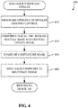
- FIG. 4 is a flowchart representative of machine readable instructions which may be executed to rollback a firmware update previously applied to the computing device of FIG. 1 .
- the example process 390 of the illustrated example of FIG. 4 begins when at least one of the PFC 130, the processor 112, or the firmware manager 105 determine that a firmware rollback is to be performed.
- the example PFC 130 assumes control of the computing device 110.
- the example PFC 130 performs a logical-OR with the existing de-feature mask and a feature update mask. (Block 420). In this manner, features that may have been enabled in the most recent firmware update are disabled. However, any other approach to disabling features that were enabled in a prior update may additionally or alternatively be used.
- the example PFC 130 then stores the OR'ed de-feature mask in the de-feature mask memory 140 as the existing de-feature mask 142. (Block 430).
- the example PFC 130 then rolls back the firmware to the recovery image (e.g., stored in the first location 137 of the firmware memory 135). (Block 440).
- the rollback to the recovery version is not performed (e.g., the updated firmware is left as-is at the processor 112).
- the new and/or updated firmware remains at the processor 112 but, on a subsequent boot of the computing device 110, has any features identified as enabled in that firmware update disabled. Control then proceeds to block 331 of FIG. 3 , where the example PFC 130 performs hardware initialization using the recently stored de-feature mask the from block 430.
- FIG. 5 is a flowchart representative of machine readable instructions 500 which may be executed to trigger an update of the firmware of the computing device 110 of FIG. 1 .
- the example process 500 of the illustrated example FIG. 5 begins when the example firmware manager 105 determines whether a new de-feature mask is available. (Block 505).
- the firmware manager 105 determines that the new de-feature mask is available in response to an indication from the firmware-providing entity 101 that a new de-feature mask is available.
- the firmware manager 105 may contact the example firmware-providing entity 101 to determine if a new de-feature mask is available.
- the firmware-providing entity 101 transmits an unsolicited notification (e.g., a push message) to the firmware manager 105 to alert the firmware manager 105 to the presence of an updated (e.g., new) de-feature mask. Alerting or otherwise informing the firmware manager 105 that a new de-feature mask is available enables the firmware-providing entity 101 to disable features in firmware that may cause vulnerabilities (e.g., to mitigate zero-day vulnerabilities). Moreover, the firmware-providing entity 101 can provide instructions (e.g., a de-feature mask) that disable a feature in the firmware.
- the example firmware manager 105 stores the de-feature mask in the de-feature mask memory. (Block 510).
- the de-feature mask represents a firmware update mask, and is associated with a firmware update.
- the firmware update mask represents features that are to be enabled after a firmware update is applied.
- the de-feature mask may be provided separately from a firmware update and may be used to indicate features that are to be disabled (e.g., features that have been identified to introduce a security vulnerability).
- the de-feature mask is stored in the de-feature mask memory 140 in an authenticated fashion.
- additional security primitives may be applied to the de-feature mask including confidentiality, integrity, replay protection, etc. to ensure the mask is not visible, modifiable, and/or open to replay attack from other system components.
- such secure communication of the firmware update and/or de-feature mask is implemented between the firmware manager 105 (and/or the operating system 150) and the PFC 130 using a Unified Extensible Firmware Interface (UEFI) Authenticated Variable mechanism as defined in the UEFI specification and implemented in the open source Extensible Firmware Interface (EFI) Development Kit II (EDKII).
- UEFI Unified Extensible Firmware Interface
- any UEFI Runtime Service caller can read an authenticated UEFI variable, however, only the holder of a private key (public key is pre-enrolled in the firmware) (e.g., the firmware manager 105) can update the variable.
- the authentication and storage of the firmware update is performed from within an isolated execution environment (e.g., an SMM) which is used to ensure secure management of the UEFI Secure Boot variables at OS runtime.
- authenticated communication between the host operating system and UEFI firmware may be utilized. While this mechanism is most often used to update firmware images, such an approach can be used to pass data from the operating system 150 to the UEFI firmware for consumption on the following boot in a similar manner to the Authenticated UEFI variable mechanism. In some examples, other approaches for providing firmware updates and/or instructions to a computing device may additionally or alternatively be used.
- firmware-providing entities e.g., an Operating System vendor, an OEM, a system administrator, etc.
- the firmware manager 105 authenticates the entity providing the update to the de-feature mask and/or firmware. On the next boot, such changes take effect.
- the firmware-providing entity 101 may provide an instruction to cause the computing device to restart (e.g., to ensure that the change take effect in a timely fashion).
- the example firmware manager 105 then sets a flag 113 indicating that a restart is required. (Block 515). Upon setting the flag 113 and/or in the event that there is no new de-feature mask (e.g., block 505 returns a result of NO), the firmware manager 105 determines whether a new firmware update is available. (Block 520). In some examples, the firmware manager 105 contacts the example firmware-providing entity 101 to determine whether a firmware update is available. In some other examples, the firmware-providing entity 101 transmits an unsolicited notification (e.g., a push message) to the firmware manager 105 to alert the firmware manager 105 to the presence of the firmware update. Alerting and/or otherwise informing the firmware manager 105 that the firmware update is available enables the firmware-providing entity 101 to provide a firmware update to the computing device 110.
- an unsolicited notification e.g., a push message
- the example firmware manager 105 stores the firmware update in the firmware memory 135. (Block 525). The example firmware manager 105 then sets the flag 113 indicating that a restart is required. (Block 530).
- the example firmware manager 105 determines whether a restart is required. (Block 535). In the illustrated example of FIG. 5 , the determination of whether a restart is required is based on whether the flag 113 has been set to indicate that a restart is required. If a restart is required (e.g., block 535 returns a result of YES), the example firmware manager 105 determines whether a restart should be performed. (Block 540). In some examples, the firmware manager 105 interacts with the processor 112 to wait for another processes to terminate, to wait until a user has agreed to the restart, etc.
- the example firmware manager 105 Upon determining that the restart should be executed (e.g., block 540 returns a result of YES), the example firmware manager 105 clears the flag 113 that indicates that a restart is required. (Block 545). The example firmware manager 105 then initiates a restart of the computing device 110. (Block 547). The restart enables the PFC 130, upon a subsequent boot, to apply a firmware update and/or disable features in an existing firmware, as described in connection with FIG. 3 . Returning to block 535, if no restart is required, the example computing device 110 continues normal operation. (Block 550). The example process of FIG.
- the receipt of the de-feature mask and the receipt of the firmware update package are represented as being performed in a serial fashion, receipt of such information may be performed in any order and/or may be performed in parallel.
- updates to the firmware and updates to the de-feature mask may be provided independently of each other. Such an approach enables firmware providers (e.g., an OEM, an OS vendor, etc.) to mitigate zero-day exploits in a timely fashion.
- FIG. 6 is a block diagram of an example processor platform 600 structured to execute the instructions of FIGS. 3 , 4 , and/or 5 to implement the computing device 110 of FIG. 1 .
- the processor platform 600 can be, for example, a server, a personal computer, a workstation, a self-learning machine (e.g., a neural network), a mobile device (e.g., a cell phone, a smart phone, a tablet such as an iPadTM), a personal digital assistant (PDA), an Internet appliance, a DVD player, a CD player, a digital video recorder, a Blu-ray player, a gaming console, a personal video recorder, a set top box, a headset or other wearable device, or any other type of computing device.
- a self-learning machine e.g., a neural network
- a mobile device e.g., a cell phone, a smart phone, a tablet such as an iPadTM
- PDA personal digital assistant
- an Internet appliance e.g.
- the processor platform 600 of the illustrated example includes a processor 612.
- the processor 612 of the illustrated example is hardware.
- the processor 612 can be implemented by one or more integrated circuits, logic circuits, microprocessors, GPUs, DSPs, or controllers from any desired family or manufacturer.
- the hardware processor may be a semiconductor based (e.g., silicon based) device.
- the processor implements the example firmware manager 105 and/or the example operating system 150.
- the processor 612 of the illustrated example includes a local memory 613 (e.g., a cache).
- the processor 612 of the illustrated example is in communication with a main memory including a volatile memory 614 and a non-volatile memory 616 via a bus 618.
- the volatile memory 614 may be implemented by Synchronous Dynamic Random Access Memory (SDRAM), Dynamic Random Access Memory (DRAM), RAMBUS® Dynamic Random Access Memory (RDRAM®) and/or any other type of random access memory device.
- the non-volatile memory 616 may be implemented by flash memory and/or any other desired type of memory device. Access to the main memory 614, 616 is controlled by a memory controller.
- the example processor platform 600 includes the platform firmware controller (PFC) 130.
- the PFC 130 of the illustrated example of FIG. 6 is implemented by a system-on-chip (SOC).
- SOC system-on-chip
- any other type of circuitry may additionally or alternatively be used such as, for example, analog or digital circuit(s), logic circuits, programmable processor(s), programmable controller(s), graphics processing unit(s) (GPU(s)), digital signal processor(s) (DSP(s)), application specific integrated circuit(s) (ASIC(s)), programmable logic device(s) (PLD(s)), field programmable logic device(s) (FPLD(s)), etc.
- the PFC communicates with the firmware manager 105 via the non-volatile memory 616 and/or the bus 618 to apply firmware to the processor 612.
- the processor platform 600 of the illustrated example also includes an interface circuit 620.
- the interface circuit 620 may be implemented by any type of interface standard, such as an Ethernet interface, a universal serial bus (USB), a Bluetooth® interface, a near field communication (NFC) interface, and/or a PCI express interface.
- one or more input devices 622 are connected to the interface circuit 620.
- the input device(s) 622 permit(s) a user to enter data and/or commands into the processor 612.
- the input device(s) can be implemented by, for example, an audio sensor, a microphone, a camera (still or video), a keyboard, a button, a mouse, a touchscreen, a track-pad, a trackball, isopoint and/or a voice recognition system.
- One or more output devices 624 are also connected to the interface circuit 620 of the illustrated example.
- the output devices 624 can be implemented, for example, by display devices (e.g., a light emitting diode (LED), an organic light emitting diode (OLED), a liquid crystal display (LCD), a cathode ray tube display (CRT), an in-place switching (IPS) display, a touchscreen, etc.), a tactile output device, a printer and/or speaker.
- display devices e.g., a light emitting diode (LED), an organic light emitting diode (OLED), a liquid crystal display (LCD), a cathode ray tube display (CRT), an in-place switching (IPS) display, a touchscreen, etc.
- the interface circuit 620 of the illustrated example thus, typically includes a graphics driver card, a graphics driver chip and/or a graphics driver processor.
- the interface circuit 620 of the illustrated example also includes a communication device such as a transmitter, a receiver, a transceiver, a modem, a residential gateway, a wireless access point, and/or a network interface to facilitate exchange of data with external machines (e.g., computing devices of any kind) via a network 626.
- the communication can be via, for example, an Ethernet connection, a digital subscriber line (DSL) connection, a telephone line connection, a coaxial cable system, a satellite system, a line-of-site wireless system, a cellular telephone system, etc.
- DSL digital subscriber line
- the processor platform 600 of the illustrated example also includes one or more mass storage devices 628 for storing software and/or data.
- mass storage devices 628 include floppy disk drives, hard drive disks, compact disk drives, Blu-ray disk drives, redundant array of independent disks (RAID) systems, and digital versatile disk (DVD) drives.
- the machine executable instructions 632 of FIGS. 3 , 4 , and/or 5 may be stored in the mass storage device 628, in the volatile memory 614, in the non-volatile memory 616, and/or on a removable non-transitory computer readable storage medium such as a CD or DVD
- example methods, apparatus and articles of manufacture have been disclosed that enable rapid response to mitigate security vulnerabilities without the need for a software and/or firmware update, as well as reduces risk of a system becoming inoperable in the field due to an unstable and/or failed firmware update.
- system components e.g., de-feature
- features may be disabled that are related to a discovered security vulnerability at the direction of a firmware-providing entity without the need to apply a new firmware to the computing device.
- the disclosed methods, apparatus and articles of manufacture improve the efficiency of using a computing device by not requiring lengthy firmware testing and/or validation cycles to be performed by a firmware-providing entity (or other entity associated with distribution of firmware). As a result, system vulnerabilities can be mitigated in a more efficient manner.
- the disclosed methods, apparatus and articles of manufacture are accordingly directed to one or more improvement(s) in the functioning of a computer.
- Example methods, apparatus, systems, and articles of manufacture for mitigating a firmware failure are disclosed herein. Further examples and combinations thereof include the following:
Landscapes
- Engineering & Computer Science (AREA)
- Theoretical Computer Science (AREA)
- Software Systems (AREA)
- General Engineering & Computer Science (AREA)
- Physics & Mathematics (AREA)
- General Physics & Mathematics (AREA)
- Computer Security & Cryptography (AREA)
- Quality & Reliability (AREA)
- Stored Programmes (AREA)
Abstract
Description
- This disclosure relates generally to firmware updates, and, more particularly, to methods and apparatus for in-field mitigation of firmware failures.
- Firmware is a type of computer software that enables control of device hardware. Firmware plays an ever-increasing role in the functionality, performance, and security of a system While firmware is typically developed and deployed (e.g., sold and/or provided) with hardware, in some cases, firmware may be updated to fix issues and/or provide new features. Firmware updates present a challenge to a computing device ecosystem.
-
-
FIG. 1 is a block diagram of an example environment of use including a computing device implemented in accordance with the teachings of this disclosure. -
FIG. 2 is an example de-feature mask that may be used by the example platform firmware controller ofFIG. 1 to enable/disable firmware features. -
FIG. 3 is a flowchart representative of machine readable instructions which may be executed to boot the computing device ofFIG. 1 . -
FIG. 4 is a flowchart representative of machine readable instructions which may be executed to rollback a firmware update previously applied to the computing device ofFIG. 1 . -
FIG. 5 is a flowchart representative of machine readable instructions which may be executed to trigger an update of the firmware of the computing device ofFIG. 1 . -
FIG. 6 is a block diagram of an example processing platform structured to execute the instructions ofFIGS. 3 ,4 , and/or 5 to implement the example computing device ofFIG. 1 . - The figures are not to scale. In general, the same reference numbers will be used throughout the drawing(s) and accompanying written description to refer to the same or like parts.
- Descriptors "first," "second," "third," etc. are used herein when identifying multiple elements or components which may be referred to separately. Unless otherwise specified or understood based on their context of use, such descriptors are not intended to impute any meaning of priority, physical order or arrangement in a list, or ordering in time but are merely used as labels for referring to multiple elements or components separately for ease of understanding the disclosed examples. In some examples, the descriptor "first" may be used to refer to an element in the detailed description, while the same element may be referred to in a claim with a different descriptor such as "second" or "third." In such instances, it should be understood that such descriptors are used merely for ease of referencing multiple elements or components.
- A firmware vendor, an original equipment manufacturer (OEM), and/or other firmware-providing entity provides firmware for use on computing devices. Generally, firmware is installed on such computing devices at a time of manufacture. However, in some scenarios, firmware is provided and/or installed while a device is operating in the field. Firmware updates can be provided to, for example, patch security vulnerabilities, provide new features, fix bugs, etc.
- Unfortunately, it is impractical for a firmware-providing entity to validate all scenarios for their products in the field (e.g., to account for various auxiliary devices that may be connected to the computing device). As a result, firmware deployment failures can occur. Such failures can result in an updated device being inoperable and/or unrecoverable. As a result, a great deal of testing is performed prior to distribution of a firmware update to attempt to ensure that devices do not become inoperable. In some examples, a firmware update and/or distribution thereof is dependent upon other entities (e.g., an OEM for integration and/or distribution). Such dependencies on OEM partners make it difficult to provide firmware updates (which may include critical security fixes) in a timely fashion.
- Examples disclosed herein reduce firmware deployment failures, as well as allow for particular features of a computing device to be enabled and/or disabled to allow for mitigation of security vulnerabilities. Example approaches disclosed herein utilize a secure de-feature mechanism that is exposed to firmware-providing entities. This allows mitigation of zero-day exploits with no firmware or software modification by remotely instructing pre-existing firmware provisioned on the computing device to de-feature (e.g., disable) the exploited feature. Moreover, examples disclosed herein utilize automated remediation in the field to perform secure firmware upgrades and/or secure firmware downgrades.
- While examples disclosed herein are described in the context of a firmware-providing entity providing a firmware update to a computing device, such firmware update does not necessarily need to be a newer version of the firmware than has been previously distributed. That is, the firmware update may represent a roll-back to a prior firmware version (e.g., to mitigate effects of an intermediate firmware update that may present vulnerabilities).
-
FIG. 1 is a block diagram of an example environment ofuse 100 including anexample computing device 110 implemented in accordance with the teachings of this disclosure. The example environment ofuse 100 includes a firmware-providingentity 101 that provides 102 a firmware update and/or a de-feature mask to afirmware manager 105 of thecomputing device 110. Theexample computing device 110 includes aprocessor 112 that implements thefirmware manager 105 and executesfirmware 115 provided by a platform firmware controller (PFC) 130. Theexample firmware manager 105 provides the firmware and/or de-feature mask (e.g., the firmware and/or de-feature mask received from the firmware-providing entity 101) to theplatform firmware controller 130 via afirmware memory 135 and/or ade-feature mask memory 140. In some examples, theexample processor 112 implements anoperating system 150 and/or other applications. - The example firmware-providing
entity 101 of the illustrated example ofFIG. 1 is implemented by a server that provides firmware updates to theexample computing device 110. In some examples, the firmware-providingentity 101 operates at the direction of a computer administrator (e.g., a remote administrator, an information technology personnel, etc.). In some examples, the firmware-providingentity 101 is operated by an operating system vendor and/or an original equipment manufacturer (OEM). However, any other party may operate the firmware-providingentity 101. In examples disclosed herein, the firmware-providingentity 101 provides firmware (e.g., a firmware update) and/or a de-feature mask to thecomputing device 110 via a network (e.g., thenetwork 626 ofFIG. 6 ) such as, for example, the Internet. In such an example, the firmware-providingentity 101 may implement a web server. However, firmware and/or de-feature masks may be provided 102 to thecomputing device 110 in any fashion such as, for example, via a physical computer-readable storage disk or storage device that is physically transported to the computing device (e.g., via postal mail). - The
example computing device 110 of the illustrated example ofFIG. 1 may be implemented by any type of computing device. In examples disclosed herein, the computing device is a desktop computer. However, any other computing device form factor may additionally or alternatively be used such as, for example, a mobile device, a server computer, an embedded computing device, an Internet of Things (IoT) computing device, etc. - In the illustrated example of
FIG. 1 , the example computing device includes theexample processor 112. Theexample processor 112 of the illustrated example ofFIG. 1 is implemented by a hardware processor. However, any other circuitry may additionally or alternatively be used such as, for example, analog or digital circuit(s), logic circuits, programmable processor(s), programmable controller(s), graphics processing unit(s) (GPU(s)), digital signal processor(s) (DSP(s)), application specific integrated circuit(s) (ASIC(s)), programmable logic device(s) (PLD(s)), field programmable logic device(s) (FPLD(s)), etc. - The
example firmware manager 105 of the illustrated example ofFIG. 1 is implemented by theprocessor 112 ofFIG. 1 . However, any other type of circuitry may additionally or alternatively be used such as, for example, analog or digital circuit(s), logic circuits, programmable processor(s), programmable controller(s), graphics processing unit(s) (GPU(s)), digital signal processor(s) (DSP(s)), application specific integrated circuit(s) (ASIC(s)), programmable logic device(s) (PLD(s)), field programmable logic device(s) (FPLD(s)), etc. Theexample firmware manager 105 communicates with the firmware-providingentity 101 to determine whether a new de-feature mask and/or a new firmware update is available. In examples disclosed herein, thefirmware manager 105 determines that the new de-feature mask is available in response to an indication from the firmware-providingentity 101 that a new de-feature mask is available. In some examples, thefirmware manager 105 may periodically and/or a-periodically contact the example firmware-providingentity 101 to determine if a new de-feature mask is available. In some other examples, the firmware-providingentity 101 transmits an unsolicited notification (e.g., a push message) to thefirmware manager 105 to alert thefirmware manager 105 to the presence of an updated (e.g., new) de-feature mask. Alerting or otherwise informing thefirmware manager 105 that a new de-feature mask is available enables the firmware-providingentity 101 to disable features in firmware that may cause vulnerabilities (e.g., to mitigate zero-day vulnerabilities). Moreover, the firmware-providingentity 101 can provide instructions (e.g., a de-feature mask) that disable a feature in the firmware. - If the
example firmware manager 105 determines that a new de-feature mask is available, theexample firmware manager 105 stores the de-feature mask in the de-featuremask memory 140. In examples disclosed herein, the de-feature mask is stored in the de-featuremask memory 140 in an authenticated fashion. That is, additional security primitives may be applied to the de-feature mask including confidentiality, integrity, replay protection, etc. to ensure the mask is not visible, modifiable, and/or open to replay attack from other system components. In examples disclosed herein, thefirmware manager 105 stores the de-feature mask in afirst location 141 of thede-feature mask memory 140, and a prior de-feature mask in asecond location 142 of thede-feature mask memory 140. Thus, in the event of a failure, the de-feature mask (e.g., which, may have been updated to enable a particular feature) may be logically combined (e.g., OR'ed) with a prior de-feature mask to again disable a recently enabled feature. - Likewise, if the
example firmware manager 105 determines that a new firmware update is available, theexample firmware manager 105 stores the firmware update in thefirmware memory 135. In examples disclosed herein, the firmware update is stored in thefirmware memory 135 in an authenticated fashion, thereby ensuring that the firmware update is not visible, modifiable, and/or open to replay attack from other system components. In examples disclosed herein, thefirmware manager 105 stores the firmware update afirst location 137 of thefirmware memory 135, and stores a prior version of the firmware (e.g., a rollback version of the firmware, a recovery version of the firmware) in asecond location 138 of thefirmware memory 135. Thus, in the event of a failure, the firmware update can be rolled back to a prior version of the firmware. - In some examples, the secure communication of the firmware update and/or de-feature mask is implemented between the firmware manager 105 (and/or the operating system 150) and the
PFC 130 using a Unified Extensible Firmware Interface (UEFI) Authenticated Variable mechanism as defined in the UEFI specification and implemented in the open source Extensible Firmware Interface (EFI) Development Kit II (EDKII). For example, using authenticated UEFI variables, any UEFI Runtime Service caller can read an authenticated UEFI variable, however, only the holder of a private key (public key is pre-enrolled in the firmware) (e.g., the firmware manager 105) can update the variable. In some examples, the authentication and storage of the firmware update is performed from within an isolated execution environment (e.g., an SMM) which is used to ensure secure management of the UEFI Secure Boot variables at OS runtime. - The
example firmware 115 of the illustrated example ofFIG. 1 represents instructions and/or information that enables control of device hardware. While firmware is typically developed and deployed (e.g., sold and/or provided) with such hardware, in some cases, firmware may be updated to fix issues and/or provide new features. Firmware updates present a challenge to a computing device ecosystem. As firmware plays an ever-increasing role in the functionality, performance, and security of a system, examples disclosed herein improve firmware deployment to update firmware in the field. In examples disclosed herein, thefirmware 115 enables theprocessor 112 to perform hardware initialization and/or tests of primary system components (e.g., components required for system functionality). In examples disclosed herein, the firmware is stored in a non-volatile memory of and/or accessible to the processor 112 (e.g., the firmware memory 135). Theexample firmware 115 is loaded into the non-volatile memory by thePFC 130. In some examples, thefirmware 115 enables theprocessor 112 to provide runtime services to a host operating system. - The example platform firmware controller (PFC) 130 of the illustrated example of
FIG. 1 is implemented by a system-on-chip (SOC). However, any other type of circuitry may additionally or alternatively be used such as, for example, analog or digital circuit(s), logic circuits, programmable processor(s), programmable controller(s), graphics processing unit(s) (GPU(s)), digital signal processor(s) (DSP(s)), application specific integrated circuit(s) (ASIC(s)), programmable logic device(s) (PLD(s)), field programmable logic device(s) (FPLD(s)), etc. In examples disclosed herein, thePFC 130, upon boot of the computing device 110 (e.g., prior to initialization of thefirmware 115 at the processor 112), determines whether there is a firmware update to be applied. In examples disclosed herein, the presence of a firmware update to be applied is determined based on, for example, the presence of a firmware update in thefirmware memory 135, the presence of a firmware update instruction (e.g., a flag indicating that an update is to be applied) in the firmware memory 135 (or any other memory), etc. - The
example PFC 130 stores the current version of the firmware as a rollback version. As used herein, a current version of firmware is a firmware package or installation (e.g., firmware file(s)) that is installed/stored in a memory of the processor 112 (e.g., thelocal memory 613 ofFIG. 6 ). In examples disclosed herein, the current firmware is moved to a location in thefirmware memory 135 that is reserved for rollback and/or recovery firmware (e.g., the second firmware memory location 138). Theexample PFC 130 then applies a firmware update (e.g., the firmware update stored in thefirst location 137 of the firmware memory 135) by copying the firmware stored in theexample firmware memory 135 to a memory of theprocessor 112. - The
example PFC 130 then determines whether the update was successful. In examples disclosed herein, theexample PFC 130 may determine whether the update was successful by reading thefirmware 115 back from the processor 112 (e.g., from thelocal memory 613 ofFIG. 6 ) to determine whether the firmware is a match for the firmware stored in thefirmware memory 135. In some examples, other checks and/or validations may be used to determine whether the update was properly applied. For example, thePFC 130 may monitor an amount of time that has elapsed since the copying of the firmware was initiated. In such an example, thePFC 130 may determine that the firmware is not correctly applied if a threshold amount of time has elapsed (e.g., if the copying of the firmware takes longer than five minutes), as such a condition may indicate a failure to write the firmware to theprocessor 112. - If the
example PFC 130 determines that the update was successful, theexample PFC 130 performs hardware initialization of theprocessor 112 using the feature update mask stored in the examplede-feature mask memory 140. If theexample PFC 130 determines that the update was not successful (or if any other error is detected during booting of thecomputing device 110 after application of the firmware update), theexample PFC 130 performs a firmware rollback to re-apply the rollback version of the firmware. During the rollback, thePFC 130 performs a logical-OR of the existing de-feature mask and the feature update mask. The result of the logical-OR operation is stored as the de-feature mask in thede-feature mask memory 140. In this manner, thePFC 130 disables features that may have been enabled in the most recent firmware update. - The
example firmware memory 135 of the illustrated example ofFIG. 1 is implemented by any memory, storage device and/or storage disc for storing data such as, for example, flash memory, magnetic media, optical media, etc. Furthermore, the data stored in thefirmware memory 135 may be in any data format such as, for example, binary data, comma delimited data, tab delimited data, structured query language (SQL) structures, etc. While in the illustrated example thefirmware memory 135 is illustrated as a single device, theexample firmware memory 135 and/or any other data storage elements described herein may be implemented by any number and/or type(s) of memories. In the illustrated example ofFIG. 1 , thefirmware memory 135 stores firmware including, for example, a firmware update provided to thefirmware manager 105 by the firmware-providingentity 101. In some examples, thefirmware memory 135 stores multiple versions of firmware including, for example, a recovery firmware version, a rollback firmware version, etc. - The example
de-feature mask memory 140 of the illustrated example ofFIG. 1 is implemented by any memory, storage device and/or storage disc for storing data such as, for example, flash memory, magnetic media, optical media, etc. In examples disclosed herein, thede-feature mask memory 140 is implemented using non-volatile storage to enable the de-feature mask to be stored across system resets and/or power loss. Furthermore, the data stored in thede-feature mask memory 140 may be in any data format such as, for example, binary data, comma delimited data, tab delimited data, structured query language (SQL) structures, etc. While in the illustrated example ofFIG. 1 , thede-feature mask memory 140 is illustrated as a single device, the examplede-feature mask memory 140 and/or any other data storage elements described herein may be implemented by any number and/or type(s) of memories. - In the illustrated example of
FIG. 1 , thede-feature mask memory 140 stores the de-feature mask and/or the feature update mask. As defined herein the de-feature mask is a bit-mask with bits corresponding to an indication of whether a particular feature is to be enabled or disabled. Likewise, the feature update mask is also a bit mask with bits corresponding to an indication of whether a particular feature is to be enabled or disabled. In examples disclosed herein, a logical value of one (1) indicates that the corresponding feature is to be disabled, and a logical value of zero (0) indicates that the corresponding feature is to be enabled. Moreover, any other mask format may additionally or alternatively be used. - In examples disclosed herein, during system initialization, the de-feature mask (or the feature update mask) is used to determine which features are to be initialized. In examples disclosed herein, the de-feature mask and/or the feature update mask includes an industry standard section (corresponding to generic features) and, in some examples, includes one or more vendor-specific sections (corresponding to features specific to that vendor). In examples disclosed herein, the de-feature mask and the feature update mask are backwards compatible for a given system.
- While in examples disclosed herein, the
PFC 130 applies a firmware update to theprocessor 112 of thecomputing device 110, thePFC 130 may apply the firmware update to any other firmware-executing circuitry of thecomputing device 110 separate from theprocessor 112 such as, for example, a baseboard management controller (BMC). In some examples, thePFC 130 may apply the firmware update to firmware-executing circuitry of a device separate from thecomputing device 110. - While in the illustrated example of
FIG. 2 , thefirmware manager 105 accesses and stores the updated firmware and/or de-feature mask for later access by thePFC 130, in some examples, thePFC 130 may be implemented by a baseband management controller (BMC) and/or any other computing circuitry (e.g., an Active Management Technology (AMT) circuit) that may communicate directly with the firmware-providingentity 101. In this manner, out-of-band remote management to enable/disable features of the computing device 110 (and/or provide firmware updates) may be achieved. -
FIG. 2 is an examplede-feature mask 200 that may be used by theexample PFC 130 ofFIG. 1 to enable/disable firmware features. The examplede-feature mask 200 is represented as an array of bits, with each bit corresponding to a respective feature to be enabled (or disabled). The examplede-feature mask 200 ofFIG. 2 includes a row ofbit identifiers 210, a row ofvalues 220, and a row of corresponding features 230. In practice, thede-feature mask 200 may be represented using only the values (e.g., without labels describing the values). In the illustrated example ofFIG. 2 , an examplefirst column 240, representing bit N having a value of zero, represents that the multi-processor feature is not to be disabled (e.g., the feature is to be enabled). An examplesecond column 242, representing bit two having a value of zero, represents that the network interface feature is not to be disabled. An examplethird column 244 representing bit one having a value of one, indicates that the system management mode (SMM) feature is to be disabled. An examplefourth column 246, representing bit zero having a value of zero, indicates that the digital rights management (DRM) feature is not to be disabled. - In the illustrated example of
FIG. 2 , the row ofvalues 220 includes single bit representations of whether a feature is to be enabled or disabled. However, in some examples, multiple bits of information may be used to specify whether a feature is to be enabled/disabled, and/or limits on feature parameters (e.g., clock speeds, voltage levels, etc.). Moreover, while in the illustrated example ofFIG. 2 , thede-feature mask 200 is represented as an array of bits, any other data structure and/or data format may additionally or alternatively be used to represent the de-feature mask. - While in the illustrated example of
FIG. 2 , four features are represented by thede-feature mask 200, any number of features to be enabled/disabled may be represented by thede-feature mask 200. Such features will vary by platform. Such features may include, for example, a limit on core usage, a limit on hyperthreading, a limit on execution speed, limits on network connectivity, limits on peripheral usage (e.g., device exposure and/or operation), limits on system power state exposure, limits on hardware feature availability and/or functionality, limits on software feature availability and/or functionality, limits on system management mode (SMM) functionality, limits on system up time, etc. - In examples disclosed herein, the presence of a feature in the
de-feature mask 200 indicates that the computing device is capable of operating with or without the feature enabled. That is, while the implementation of features exposed by thede-feature mask 200 may vary by platform, in order to maintain a working system, critical system resources are not allowed to be fully disabled. Such an approach ensures and/or increases the likelihood that the device is able to exit the de-featured state (e.g., at a later time when a new firmware update is provided). Example resources that might be considered critical system resources are, for example, at least a single core to execute instructions, main memory that firmware and/or an operating system can access, a graphical user interface, a power connection, a display driver, a user input device, etc. - While an example manner of implementing the
computing device 110 is illustrated inFIG. 1 , one or more of the elements, processes and/or devices illustrated inFIG. 1 may be combined, divided, re-arranged, omitted, eliminated and/or implemented in any other way. Further, theexample firmware manager 105, the exampleplatform firmware controller 130, and/or, more generally, theexample computing device 110 ofFIG. 1 may be implemented by hardware, software, firmware and/or any combination of hardware, software and/or firmware. Thus, for example, any of theexample firmware manager 105, the exampleplatform firmware controller 130, and/or, more generally, theexample computing device 110 ofFIG. 1 could be implemented by one or more analog or digital circuit(s), logic circuits, programmable processor(s), programmable controller(s), graphics processing unit(s) (GPU(s)), digital signal processor(s) (DSP(s)), application specific integrated circuit(s) (ASIC(s)), programmable logic device(s) (PLD(s)) and/or field programmable logic device(s) (FPLD(s)). When reading any of the apparatus or system claims of this patent to cover a purely software and/or firmware implementation, at least one of theexample firmware manager 105, the exampleplatform firmware controller 130, and/or, more generally, theexample computing device 110 ofFIG. 1 is/are hereby expressly defined to include a non-transitory computer readable storage device or storage disk such as a memory, a digital versatile disk (DVD), a compact disk (CD), a Blu-ray disk, etc. including the software and/or firmware. Further still, theexample computing device 110 may include one or more elements, processes and/or devices in addition to, or instead of, those illustrated inFIG. 1 , and/or may include more than one of any or all of the illustrated elements, processes and devices. As used herein, the phrase "in communication," including variations thereof, encompasses direct communication and/or indirect communication through one or more intermediary components, and does not require direct physical (e.g., wired) communication and/or constant communication, but rather additionally includes selective communication at periodic intervals, scheduled intervals, aperiodic intervals, and/or one-time events. - Flowcharts representative of example hardware logic, machine readable instructions, hardware implemented state machines, and/or any combination thereof for implementing the
computing device 110 ofFIG. 1 are shown inFIGS. 3 ,4 , and/or 5. The machine readable instructions may be one or more executable programs or portion(s) of an executable program for execution by a computer processor such as theprocessor 612 shown in theexample processor platform 600 discussed below in connection withFIG. 6 . The program may be embodied in software stored on a non-transitory computer readable storage medium such as a CD-ROM, a floppy disk, a hard drive, a DVD, a Blu-ray disk, or a memory associated with theprocessor 612, but the entire program and/or parts thereof could alternatively be executed by a device other than theprocessor 612 and/or embodied in firmware or dedicated hardware. Further, although the example program is described with reference to the flowcharts illustrated inFIGS. 3 ,4 , and/or 5, many other methods of implementing theexample computing device 110 may alternatively be used. For example, the order of execution of the blocks may be changed, and/or some of the blocks described may be changed, eliminated, or combined. Additionally or alternatively, any or all of the blocks may be implemented by one or more hardware circuits (e.g., discrete and/or integrated analog and/or digital circuitry, an FPGA, an ASIC, a comparator, an operational-amplifier (op-amp), a logic circuit, etc.) structured to perform the corresponding operation without executing software or firmware. - The machine readable instructions described herein may be stored in one or more of a compressed format, an encrypted format, a fragmented format, a packaged format, etc. Machine readable instructions as described herein may be stored as data (e.g., portions of instructions, code, representations of code, etc.) that may be utilized to create, manufacture, and/or produce machine executable instructions. For example, the machine readable instructions may be fragmented and stored on one or more storage devices and/or computing devices (e.g., servers). The machine readable instructions may require one or more of installation, modification, adaptation, updating, combining, supplementing, configuring, decryption, decompression, unpacking, distribution, reassignment, etc. in order to make them directly readable and/or executable by a computing device and/or other machine. For example, the machine readable instructions may be stored in multiple parts, which are individually compressed, encrypted, and stored on separate computing devices, wherein the parts when decrypted, decompressed, and combined form a set of executable instructions that implement a program such as that described herein. In another example, the machine readable instructions may be stored in a state in which they may be read by a computer, but require addition of a library (e.g., a dynamic link library (DLL)), a software development kit (SDK), an application programming interface (API), etc. in order to execute the instructions on a particular computing device or other device. In another example, the machine readable instructions may need to be configured (e.g., settings stored, data input, network addresses recorded, etc.) before the machine readable instructions and/or the corresponding program(s) can be executed in whole or in part. Thus, the disclosed machine readable instructions and/or corresponding program(s) are intended to encompass such machine readable instructions and/or program(s) regardless of the particular format or state of the machine readable instructions and/or program(s) when stored or otherwise at rest or in transit.
- As mentioned above, the example processes of
FIGS. 3 ,4 , and/or 5 may be implemented using executable instructions (e.g., computer and/or machine readable instructions) stored on a non-transitory computer and/or machine readable medium such as a hard disk drive, a flash memory, a read-only memory, a compact disk, a digital versatile disk, a cache, a random-access memory and/or any other storage device or storage disk in which information is stored for any duration (e.g., for extended time periods, permanently, for brief instances, for temporarily buffering, and/or for caching of the information). As used herein, the term non-transitory computer readable medium is expressly defined to include any type of computer readable storage device and/or storage disk and to exclude propagating signals and to exclude transmission media. - "Including" and "comprising" (and all forms and tenses thereof) are used herein to be open ended terms. Thus, whenever a claim employs any form of "include" or "comprise" (e.g., comprises, includes, comprising, including, having, etc.) as a preamble or within a claim recitation of any kind, it is to be understood that additional elements, terms, etc. may be present without falling outside the scope of the corresponding claim or recitation. As used herein, when the phrase "at least" is used as the transition term in, for example, a preamble of a claim, it is open-ended in the same manner as the term "comprising" and "including" are open ended. The term "and/or" when used, for example, in a form such as A, B, and/or C refers to any combination or subset of A, B, C such as (1) A alone, (2) B alone, (3) C alone, (4) A with B, (5) A with C, (6) B with C, and (7) A with B and with C. As used herein in the context of describing structures, components, items, objects and/or things, the phrase "at least one of A and B" is intended to refer to implementations including any of (1) at least one A, (2) at least one B, and (3) at least one A and at least one B. Similarly, as used herein in the context of describing structures, components, items, objects and/or things, the phrase "at least one of A or B" is intended to refer to implementations including any of (1) at least one A, (2) at least one B, and (3) at least one A and at least one B. As used herein in the context of describing the performance or execution of processes, instructions, actions, activities and/or steps, the phrase "at least one of A and B" is intended to refer to implementations including any of (1) at least one A, (2) at least one B, and (3) at least one A and at least one B. Similarly, as used herein in the context of describing the performance or execution of processes, instructions, actions, activities and/or steps, the phrase "at least one of A or B" is intended to refer to implementations including any of (1) at least one A, (2) at least one B, and (3) at least one A and at least one B.
-
FIG. 3 is a flowchart representative of machine readable instructions which may be executed to boot thecomputing device 110 ofFIG. 1 . Theexample process 300 of the illustrated example ofFIG. 3 begins when theexample PFC 130 determines whether there is a firmware update to be applied. (Block 310). In examples disclosed herein, the presence of a firmware update to be applied is determined based on, for example, the presence of a firmware update in thefirmware memory 135, the presence of a firmware update instruction (e.g., a flag indicating that an update is to be applied) in the firmware memory 135 (or any other memory), etc. If there is no firmware update to be applied (e.g., block 310 returns a result of NO), thePFC 130 performs hardware initialization using the de-feature mask stored in thede-feature mask memory 140. (Block 311). In some examples, the de-feature mask may be updated independently of the firmware. - If there is a firmware update to be applied (e.g., block 310 returns a result of YES), the
example PFC 130 stores the current version of the firmware as a rollback version. (Block 315). In the illustrated example ofFIG. 3 , the current firmware is moved to a location in thefirmware memory 135 that is reserved for rollback and/or recovery firmware (e.g., the second firmware memory location 138). - The
example PFC 130 then applies a firmware update (e.g., the firmware update stored in the firmware memory) by copying the firmware stored in theexample firmware memory 135 to a memory of theprocessor 112. (Block 320). Theexample PFC 130 then determines whether the update was successful. (Block 325). In examples disclosed herein, theexample PFC 130 may determine whether the update was successful by reading the firmware back from theprocessor 112 to determine whether the firmware is a match for the firmware stored in thefirmware memory 135. In some examples, other checks and/or validations may be used to determine whether the update was properly applied. For example, thePFC 130 may monitor an amount of time that has elapsed since the copying of the firmware was initiated. In such an example, thePFC 130 may determine that the firmware is not correctly applied if a threshold amount of time has elapsed (e.g., if the copying of the firmware takes longer than five minutes), as such a condition may indicate a failure to write the firmware to theprocessor 112. - If the
example PFC 130 determines that the update was successful (e.g., block 325 returns result of YES), theexample PFC 130 performs hardware initialization using the feature update mask stored in the examplede-feature mask memory 140. (Block 331). If theexample PFC 130 determines that the update was not successful (e.g., block 325 returns a result of NO) theexample PFC 130 performs a firmware rollback. (Block 390). An example process for performing the rollback is described below in connection withFIG. 4 . - After initializing the hardware (block 311 or block 331), the
processor 112, using thefirmware 115, determines whether the firmware is executing. (Block 335). If the firmware is not executing (e.g., block 335 returns a result of NO) theexample PFC 130 performs the firmware rollback. (Block 390). In some examples, thePFC 130 additionally monitors to determine whether the firmware is executing atblock 335. Such an approach ensures that if theprocessor 112 does not begin executing the firmware, the rollback procedure ofblock 390 can be initiated. - If the
example processor 112 and/or thePFC 130 determines that the firmware is executing (e.g. block 335 returns a result of YES), theexample processor 112 using thefirmware 115 tests one or more primary system components. (Block 340). Primary system components may include, for example, power supplies, processing units, memory, etc. Theexample processor 112, using thefirmware 115, determines whether the one or more primary system component(s) are functional. (Block 345). If theexample processor 112 determines that one of the one or more primary system components is not functional (e.g., block 345 returns a result of NO in connection with any of the primary system components), theexample PFC 130 performs the firmware rollback. (Block 390). - If all of the one or more primary system components are functional (e.g., block 345 returns result of YES), the
example processor 112, using thefirmware 115, boots theoperating system 150. (Block 350). Theexample processor 112 determines whether theoperating system 150 is booted within a threshold amount of time. (Block 335). In some examples, the threshold amount of time is five minutes. However, any other threshold may additionally or alternatively be used. In some examples, thefirmware manager 105, operated by theprocessor 112, determines whether theoperating system 150 has been booted within the threshold amount of time atblock 355. If theoperating system 150 has booted (e.g., block 355 returns result of YES), the firmware update is considered successful and operation of thecomputing device 110 proceeds. However, if theoperating system 150 is not booted within the threshold period of time (e.g. block 355 returns result of NO) control is passed to thePFC 130 where the firmware update is rolled back. (Block 390). - In the illustrated example of
FIG. 3 , the determinations performed atblocks FIG. 3 , numerous checkpoints and/or validations are used to implement a secure and automated rollback of firmware if a severe impact to stability is encountered (e.g. a Windows BSOD, a failure to boot, a failure to apply firmware, etc.). In the event of a rollback, a vulnerable feature can be disabled using thede-feature mask 200 described inFIG. 2 . Thus, until a new firmware update is deployed, such features can remain disabled to prevent any vulnerabilities that may be associated with those features. -
FIG. 4 is a flowchart representative of machine readable instructions which may be executed to rollback a firmware update previously applied to the computing device ofFIG. 1 . Theexample process 390 of the illustrated example ofFIG. 4 begins when at least one of thePFC 130, theprocessor 112, or thefirmware manager 105 determine that a firmware rollback is to be performed. To initiate the rollback, theexample PFC 130 assumes control of thecomputing device 110. (Block 410). Theexample PFC 130 performs a logical-OR with the existing de-feature mask and a feature update mask. (Block 420). In this manner, features that may have been enabled in the most recent firmware update are disabled. However, any other approach to disabling features that were enabled in a prior update may additionally or alternatively be used. Theexample PFC 130 then stores the OR'ed de-feature mask in thede-feature mask memory 140 as the existingde-feature mask 142. (Block 430). Theexample PFC 130 then rolls back the firmware to the recovery image (e.g., stored in thefirst location 137 of the firmware memory 135). (Block 440). In some examples, the rollback to the recovery version is not performed (e.g., the updated firmware is left as-is at the processor 112). In this manner, the new and/or updated firmware remains at theprocessor 112 but, on a subsequent boot of thecomputing device 110, has any features identified as enabled in that firmware update disabled. Control then proceeds to block 331 ofFIG. 3 , where theexample PFC 130 performs hardware initialization using the recently stored de-feature mask the fromblock 430. -
FIG. 5 is a flowchart representative of machinereadable instructions 500 which may be executed to trigger an update of the firmware of thecomputing device 110 ofFIG. 1 . Theexample process 500 of the illustrated exampleFIG. 5 begins when theexample firmware manager 105 determines whether a new de-feature mask is available. (Block 505). In examples disclosed herein, thefirmware manager 105 determines that the new de-feature mask is available in response to an indication from the firmware-providingentity 101 that a new de-feature mask is available. In some examples, thefirmware manager 105 may contact the example firmware-providingentity 101 to determine if a new de-feature mask is available. In some other examples, the firmware-providingentity 101 transmits an unsolicited notification (e.g., a push message) to thefirmware manager 105 to alert thefirmware manager 105 to the presence of an updated (e.g., new) de-feature mask. Alerting or otherwise informing thefirmware manager 105 that a new de-feature mask is available enables the firmware-providingentity 101 to disable features in firmware that may cause vulnerabilities (e.g., to mitigate zero-day vulnerabilities). Moreover, the firmware-providingentity 101 can provide instructions (e.g., a de-feature mask) that disable a feature in the firmware. - If a new de-feature mask is available (e.g., block 505 returns a result of YES), the
example firmware manager 105 stores the de-feature mask in the de-feature mask memory. (Block 510). In some examples the de-feature mask represents a firmware update mask, and is associated with a firmware update. In such an example, the firmware update mask represents features that are to be enabled after a firmware update is applied. Conversely, in some examples, the de-feature mask may be provided separately from a firmware update and may be used to indicate features that are to be disabled (e.g., features that have been identified to introduce a security vulnerability). - In examples disclosed herein, the de-feature mask is stored in the
de-feature mask memory 140 in an authenticated fashion. In some examples, additional security primitives may be applied to the de-feature mask including confidentiality, integrity, replay protection, etc. to ensure the mask is not visible, modifiable, and/or open to replay attack from other system components. In some examples, such secure communication of the firmware update and/or de-feature mask is implemented between the firmware manager 105 (and/or the operating system 150) and thePFC 130 using a Unified Extensible Firmware Interface (UEFI) Authenticated Variable mechanism as defined in the UEFI specification and implemented in the open source Extensible Firmware Interface (EFI) Development Kit II (EDKII). For example, using authenticated UEFI variables, any UEFI Runtime Service caller can read an authenticated UEFI variable, however, only the holder of a private key (public key is pre-enrolled in the firmware) (e.g., the firmware manager 105) can update the variable. In some examples, the authentication and storage of the firmware update is performed from within an isolated execution environment (e.g., an SMM) which is used to ensure secure management of the UEFI Secure Boot variables at OS runtime. - In some examples, authenticated communication between the host operating system and UEFI firmware may be utilized. While this mechanism is most often used to update firmware images, such an approach can be used to pass data from the
operating system 150 to the UEFI firmware for consumption on the following boot in a similar manner to the Authenticated UEFI variable mechanism. In some examples, other approaches for providing firmware updates and/or instructions to a computing device may additionally or alternatively be used. - In some examples, only particular firmware-providing entities (e.g., an Operating System vendor, an OEM, a system administrator, etc.) are allowed to make updates to the de-feature mask and/or the firmware. In such an example, the
firmware manager 105 authenticates the entity providing the update to the de-feature mask and/or firmware. On the next boot, such changes take effect. In such examples, the firmware-providingentity 101 may provide an instruction to cause the computing device to restart (e.g., to ensure that the change take effect in a timely fashion). - The
example firmware manager 105 then sets aflag 113 indicating that a restart is required. (Block 515). Upon setting theflag 113 and/or in the event that there is no new de-feature mask (e.g., block 505 returns a result of NO), thefirmware manager 105 determines whether a new firmware update is available. (Block 520). In some examples, thefirmware manager 105 contacts the example firmware-providingentity 101 to determine whether a firmware update is available. In some other examples, the firmware-providingentity 101 transmits an unsolicited notification (e.g., a push message) to thefirmware manager 105 to alert thefirmware manager 105 to the presence of the firmware update. Alerting and/or otherwise informing thefirmware manager 105 that the firmware update is available enables the firmware-providingentity 101 to provide a firmware update to thecomputing device 110. - If a firmware update is available (e.g., block 520 returns a result of YES), the
example firmware manager 105 stores the firmware update in thefirmware memory 135. (Block 525). Theexample firmware manager 105 then sets theflag 113 indicating that a restart is required. (Block 530). - Upon setting the
flag 113 atblock 530, and/or in response to determining that no firmware update is available (e.g., block 520 returns a result of NO), theexample firmware manager 105 determines whether a restart is required. (Block 535). In the illustrated example ofFIG. 5 , the determination of whether a restart is required is based on whether theflag 113 has been set to indicate that a restart is required. If a restart is required (e.g., block 535 returns a result of YES), theexample firmware manager 105 determines whether a restart should be performed. (Block 540). In some examples, thefirmware manager 105 interacts with theprocessor 112 to wait for another processes to terminate, to wait until a user has agreed to the restart, etc. - Upon determining that the restart should be executed (e.g., block 540 returns a result of YES), the
example firmware manager 105 clears theflag 113 that indicates that a restart is required. (Block 545). Theexample firmware manager 105 then initiates a restart of thecomputing device 110. (Block 547). The restart enables thePFC 130, upon a subsequent boot, to apply a firmware update and/or disable features in an existing firmware, as described in connection withFIG. 3 . Returning to block 535, if no restart is required, theexample computing device 110 continues normal operation. (Block 550). The example process ofFIG. 5 then terminates, but may be re-executed periodically (e.g., every hour, every day, etc.) and/or a-periodically (e.g., upon a subsequent initialization of theoperating system 150, in response to a message from the firmware-providingentity 101, in response to a user request, etc.) - While in the illustrated example of
FIG. 5 , the receipt of the de-feature mask and the receipt of the firmware update package are represented as being performed in a serial fashion, receipt of such information may be performed in any order and/or may be performed in parallel. Importantly, updates to the firmware and updates to the de-feature mask may be provided independently of each other. Such an approach enables firmware providers (e.g., an OEM, an OS vendor, etc.) to mitigate zero-day exploits in a timely fashion. -
FIG. 6 is a block diagram of anexample processor platform 600 structured to execute the instructions ofFIGS. 3 ,4 , and/or 5 to implement thecomputing device 110 ofFIG. 1 . Theprocessor platform 600 can be, for example, a server, a personal computer, a workstation, a self-learning machine (e.g., a neural network), a mobile device (e.g., a cell phone, a smart phone, a tablet such as an iPad™), a personal digital assistant (PDA), an Internet appliance, a DVD player, a CD player, a digital video recorder, a Blu-ray player, a gaming console, a personal video recorder, a set top box, a headset or other wearable device, or any other type of computing device. - The
processor platform 600 of the illustrated example includes aprocessor 612. Theprocessor 612 of the illustrated example is hardware. For example, theprocessor 612 can be implemented by one or more integrated circuits, logic circuits, microprocessors, GPUs, DSPs, or controllers from any desired family or manufacturer. The hardware processor may be a semiconductor based (e.g., silicon based) device. In this example, the processor implements theexample firmware manager 105 and/or theexample operating system 150. - The
processor 612 of the illustrated example includes a local memory 613 (e.g., a cache). Theprocessor 612 of the illustrated example is in communication with a main memory including avolatile memory 614 and anon-volatile memory 616 via abus 618. Thevolatile memory 614 may be implemented by Synchronous Dynamic Random Access Memory (SDRAM), Dynamic Random Access Memory (DRAM), RAMBUS® Dynamic Random Access Memory (RDRAM®) and/or any other type of random access memory device. Thenon-volatile memory 616 may be implemented by flash memory and/or any other desired type of memory device. Access to themain memory - The
example processor platform 600 includes the platform firmware controller (PFC) 130. ThePFC 130 of the illustrated example ofFIG. 6 is implemented by a system-on-chip (SOC). However, any other type of circuitry may additionally or alternatively be used such as, for example, analog or digital circuit(s), logic circuits, programmable processor(s), programmable controller(s), graphics processing unit(s) (GPU(s)), digital signal processor(s) (DSP(s)), application specific integrated circuit(s) (ASIC(s)), programmable logic device(s) (PLD(s)), field programmable logic device(s) (FPLD(s)), etc. The PFC communicates with thefirmware manager 105 via thenon-volatile memory 616 and/or thebus 618 to apply firmware to theprocessor 612. - The
processor platform 600 of the illustrated example also includes aninterface circuit 620. Theinterface circuit 620 may be implemented by any type of interface standard, such as an Ethernet interface, a universal serial bus (USB), a Bluetooth® interface, a near field communication (NFC) interface, and/or a PCI express interface. - In the illustrated example, one or
more input devices 622 are connected to theinterface circuit 620. The input device(s) 622 permit(s) a user to enter data and/or commands into theprocessor 612. The input device(s) can be implemented by, for example, an audio sensor, a microphone, a camera (still or video), a keyboard, a button, a mouse, a touchscreen, a track-pad, a trackball, isopoint and/or a voice recognition system. - One or
more output devices 624 are also connected to theinterface circuit 620 of the illustrated example. Theoutput devices 624 can be implemented, for example, by display devices (e.g., a light emitting diode (LED), an organic light emitting diode (OLED), a liquid crystal display (LCD), a cathode ray tube display (CRT), an in-place switching (IPS) display, a touchscreen, etc.), a tactile output device, a printer and/or speaker. Theinterface circuit 620 of the illustrated example, thus, typically includes a graphics driver card, a graphics driver chip and/or a graphics driver processor. - The
interface circuit 620 of the illustrated example also includes a communication device such as a transmitter, a receiver, a transceiver, a modem, a residential gateway, a wireless access point, and/or a network interface to facilitate exchange of data with external machines (e.g., computing devices of any kind) via anetwork 626. The communication can be via, for example, an Ethernet connection, a digital subscriber line (DSL) connection, a telephone line connection, a coaxial cable system, a satellite system, a line-of-site wireless system, a cellular telephone system, etc. - The
processor platform 600 of the illustrated example also includes one or moremass storage devices 628 for storing software and/or data. Examples of suchmass storage devices 628 include floppy disk drives, hard drive disks, compact disk drives, Blu-ray disk drives, redundant array of independent disks (RAID) systems, and digital versatile disk (DVD) drives. - The machine
executable instructions 632 ofFIGS. 3 ,4 , and/or 5 may be stored in themass storage device 628, in thevolatile memory 614, in thenon-volatile memory 616, and/or on a removable non-transitory computer readable storage medium such as a CD or DVD - From the foregoing, it will be appreciated that example methods, apparatus and articles of manufacture have been disclosed that enable rapid response to mitigate security vulnerabilities without the need for a software and/or firmware update, as well as reduces risk of a system becoming inoperable in the field due to an unstable and/or failed firmware update. For example, by allowing system components to disable (e.g., de-feature) features of the computing system, features may be disabled that are related to a discovered security vulnerability at the direction of a firmware-providing entity without the need to apply a new firmware to the computing device. The disclosed methods, apparatus and articles of manufacture improve the efficiency of using a computing device by not requiring lengthy firmware testing and/or validation cycles to be performed by a firmware-providing entity (or other entity associated with distribution of firmware). As a result, system vulnerabilities can be mitigated in a more efficient manner. The disclosed methods, apparatus and articles of manufacture are accordingly directed to one or more improvement(s) in the functioning of a computer.
- Example methods, apparatus, systems, and articles of manufacture for mitigating a firmware failure are disclosed herein. Further examples and combinations thereof include the following:
- Example 1 includes an apparatus to mitigate firmware failure, the apparatus comprising at least one hardware processor, first memory including instructions to be executed by the at least one hardware processor, mask memory including a feature mask associated with a first firmware version, the feature mask identifying features of the first firmware version to be disabled, and a platform firmware controller to apply the first firmware version to the first memory for execution by the at least one processor, initialize the at least one processor using the feature mask, in response to a detection of a failure determine a first de-feature mask based on a second de-feature mask previously used by the at least one processor and the feature update mask, and initialize the at least one processor using the first de-feature mask.
- Example 2 includes the apparatus of example 1, wherein the platform firmware controller is further to determine the first de-feature mask by performing a logical-OR of the second de-feature mask and the feature update mask.
- Example 3 includes the apparatus of example 2, wherein the first de-feature mask is to disable a feature of the at least one processor that was enabled via the feature mask.
- Example 4 includes the apparatus of example 1, wherein the platform firmware controller is to apply a rollback version of the firmware to the at least one processor prior to the initialization of the at least one processor using the first de-feature mask.
- Example 5 includes the apparatus of any one of examples 1-4, wherein the platform firmware controller is to further to access the first firmware version provided by a firmware-providing entity, the firmware-providing entity separate from the at least one processor.
- Example 6 includes the apparatus of any one of examples 1-5, wherein the platform firmware controller is to detect the failure by determining whether the application of the first firmware version to the at least one processor was successful.
- Example 7 includes the apparatus of any one of examples 1-5, wherein platform firmware controller is to detect the failure by determining if a primary system component is functional after the initialization of the at least one processor using the feature mask.
- Example 8 includes the apparatus of any one of examples 1-5, wherein platform firmware controller is to detect the failure by determining if an operating system is booted within a threshold amount of time of the initialization of the at least one processor using the first feature mask.
- Example 9 includes At least one non-transitory computer readable storage medium comprising instructions that, when executed by a platform firmware controller, cause the platform firmware controller to at least apply a first firmware version to a processor separate from the platform firmware controller, initialize the processor using a feature mask associated with the first firmware version, the feature mask identifying features of the first firmware version to be disabled, and in response to a detection of a failure determine a first de-feature mask based on a second de-feature mask previously used by the processor and the feature update mask, and initialize the processor using the first de-feature mask.
- Example 10 includes the computer readable storage medium of example 9, wherein the instructions, when executed, cause the platform firmware controller to determine the first de-feature mask by performing a logical-OR of the second de-feature mask and the feature update mask.
- Example 11 includes the computer readable storage medium of example 10, wherein the first de-feature mask is to disable a feature of the processor that was enabled via the feature mask.
- Example 12 includes the computer readable storage medium of example 9, wherein the instructions, when executed, cause the platform firmware controller to initialize the processor using the first de-feature mask while executing the first firmware version.
- Example 13 includes the computer readable storage medium of any one of examples 9-12, wherein the instructions, when executed, cause the platform firmware controller apply a rollback version of the firmware to the processor prior to initializing the processor using the first de-feature mask.
- Example 14 includes the computer readable storage medium of any one of examples 9-13, wherein the instructions, when executed, cause the platform firmware controller to access the first firmware version provided by a firmware-providing entity, the firmware-providing entity separate from the processor.
- Example 15 includes the computer readable storage medium of any one of examples 9-14, wherein the instructions, when executed, cause the platform firmware controller detect the failure by determining if the application of the first firmware version to the processor was successful.
- Example 16 includes the computer readable storage medium of any one of examples 9-14, wherein the instructions, when executed, cause the platform firmware controller to detect the failure by determining if primary system components are functional after initializing the processor using the feature mask.
- Example 17 includes the computer readable storage medium of any one of examples 9-14, wherein the instructions, when executed, cause the platform firmware controller to detect the failure by determining if an operating system is booted within a threshold amount of time of the initialization of the processor using the first feature mask.
- Example 18 includes a method of mitigating a firmware failure, the method comprising applying a first firmware version to a processor, initializing the processor using a feature mask associated with the first firmware version, the feature mask identifying features of the first firmware version to be disabled, in response to a detection of a failure determining a first de-feature mask based on a second de-feature mask previously used by the processor and the feature update mask, and initializing the processor using the first de-feature mask.
- Example 19 includes the method of example 18, wherein the determining of the first de-feature mask includes performing a logical-OR of the second de-feature mask and the feature update mask.
- Example 20 includes the method of example 19, wherein the first de-feature mask is to disable a feature of the processor that was enabled via the feature mask.
- Example 21 includes the method of any one of examples 18-20, wherein the initializing of the processor using the first de-feature mask is further performed using the first firmware version.
- Example 22 includes the method of any one of examples 18-21, further including applying a rollback version of the firmware to the processor prior to initializing the processor using the first de-feature mask.
- Example 23 includes the method of any one of examples 18-22, further including accessing the first firmware version provided by a firmware-providing entity, the firmware-providing entity separate from the processor.
- Example 24 includes the method of any one of examples 18-23, further including detecting the failure by determining if the application of the first firmware version to the processor was successful.
- Example 25 includes the method of any one of examples 18-23, further including detecting the failure by determining if primary system components are functional after initializing the processor using the feature mask.
- Example 26 includes the method of any one of examples 18-23, further including detecting the failure by determining if an operating system is booted within a threshold amount of time of the initialization of the processor using the first feature mask.
- Although certain example methods, apparatus and articles of manufacture have been disclosed herein, the scope of coverage of this patent is not limited thereto. On the contrary, this patent covers all methods, apparatus and articles of manufacture fairly falling within the scope of the claims of this patent.
Claims (15)
- An apparatus to mitigate firmware failure, the apparatus comprising:at least one hardware processor 112;first memory 135 including instructions to be executed by the at least one hardware processor 112;mask memory 140 including a feature mask associated with a first firmware version 137, the feature mask identifying features of the first firmware version 137 to be disabled; anda platform firmware controller 130 to:apply the first firmware version 137 to the first memory 135 for execution by the at least one processor 112;initialize the at least one processor 112 using the feature mask;in response to a detection of a failure:determine a first de-feature mask 141 based on a second de-feature mask 142 previously used by the at least one processor 112 and the feature update mask; andinitialize the at least one processor 112 using the first de-feature mask 141.
- The apparatus of claim 1, wherein the platform firmware controller 130 is further to determine the first de-feature mask 141 by performing a logical-OR of the second de-feature mask 142 and the feature update mask.
- The apparatus of claim 2, wherein the first de-feature mask 141 is to disable a feature that was enabled via the feature mask.
- The apparatus of claim 1, wherein the platform firmware controller 130 is to apply a rollback version of the firmware for execution by the at least one processor 112 prior to the initialization of the at least one processor 112 using the first de-feature mask 141.
- The apparatus of any one of claims 1-4, wherein the platform firmware controller 130 is to access the first firmware version 137 provided by a firmware-providing entity, the firmware-providing entity separate from the at least one processor 112.
- The apparatus of any one of claims 1-4, wherein the platform firmware controller 130 is to detect the failure by determining whether the execution of the first firmware version 137 by at least one processor 112 was successful.
- The apparatus of any one of claims 1-4, wherein the platform firmware controller 130 is to detect the failure by determining if a primary system component is functional after the initialization of the at least one processor 112 using the feature mask.
- The apparatus of any one of claims 1-4, wherein platform firmware controller 130 is to detect the failure by determining if an operating system is booted within a threshold amount of time of the initialization of the at least one processor 112 using the first feature mask.
- A method of mitigating a firmware failure, the method comprising:applying a first firmware version 137 for execution by a processor 112;initializing the processor 112 using a feature mask associated with the first firmware version 137, the feature mask identifying features of the first firmware version 137 to be disabled;in response to a detection of a failure:determining a first de-feature mask 141 based on a second de-feature mask 142 previously used by the processor 112 and the feature update mask; andinitializing the processor 112 using the first de-feature mask 141.
- The method of claim 9 wherein the determining of the first de-feature mask 141 includes performing a logical-OR of the second de-feature mask 142 and the feature update mask.
- The method of claim 10, wherein the first de-feature mask 141 is to disable a feature that was enabled via the feature mask.
- The method of any one of claims 9-11, wherein the initializing of the processor 112 using the first de-feature mask 141 is further performed using the first firmware version 137.
- The method of any one of claims 9-11, further including applying a rollback version of the firmware prior to initializing the processor 112 using the first de-feature mask 141.
- The method of any one of claims 9-11, further including accessing the first firmware version 137 provided by a firmware-providing entity, the firmware-providing entity separate from the processor 112.
- At least one computer readable storage medium having instructions stored thereon that, when executed, cause a machine to perform the method of any one of claims 9-14.
Applications Claiming Priority (1)
| Application Number | Priority Date | Filing Date | Title |
|---|---|---|---|
| US16/370,962 US11288124B2 (en) | 2019-03-30 | 2019-03-30 | Methods and apparatus for in-field mitigation of firmware failures |
Publications (1)
| Publication Number | Publication Date |
|---|---|
| EP3719635A1 true EP3719635A1 (en) | 2020-10-07 |
Family
ID=67299346
Family Applications (1)
| Application Number | Title | Priority Date | Filing Date |
|---|---|---|---|
| EP20161582.0A Withdrawn EP3719635A1 (en) | 2019-03-30 | 2020-03-06 | Methods and apparatus for in-field mitigation of firmware failures |
Country Status (3)
| Country | Link |
|---|---|
| US (1) | US11288124B2 (en) |
| EP (1) | EP3719635A1 (en) |
| CN (1) | CN111767066A (en) |
Cited By (1)
| Publication number | Priority date | Publication date | Assignee | Title |
|---|---|---|---|---|
| WO2023277881A1 (en) * | 2021-06-29 | 2023-01-05 | Hewlett-Packard Development Company, L.P. | Instruction updates to hardware devices |
Families Citing this family (10)
| Publication number | Priority date | Publication date | Assignee | Title |
|---|---|---|---|---|
| US11461163B1 (en) * | 2019-06-28 | 2022-10-04 | Amazon Technologies, Inc. | Remote device error correction |
| US20190325139A1 (en) * | 2019-06-28 | 2019-10-24 | Intel Corporation | Secure updating of computing system firmware |
| US12001827B2 (en) * | 2020-07-27 | 2024-06-04 | Dell Products L.P | System and method for system-wide firmware downgrade control |
| US11416615B2 (en) * | 2020-09-02 | 2022-08-16 | Dell Products, L.P. | Configuring trusted remote management communications using UEFI |
| US11467912B2 (en) * | 2020-10-22 | 2022-10-11 | Dell Products L.P. | Feature toggle management with application behavior point-in-time restoration using event sourcing |
| US11599436B2 (en) * | 2021-03-02 | 2023-03-07 | Dell Products L.P. | Systems and methods for repairing corruption to BIOS boot critical memory variables |
| EP4109237A1 (en) * | 2021-06-22 | 2022-12-28 | ABB Schweiz AG | Computer-implemented method for updating a process control system |
| US12181974B2 (en) * | 2021-09-22 | 2024-12-31 | Texas Instruments Incorporated | Techniques for peripheral utilization metrics collection and reporting |
| CN117980881A (en) * | 2021-10-17 | 2024-05-03 | 利盟国际有限公司 | Method for updating electronic equipment |
| US20220100495A1 (en) * | 2021-12-09 | 2022-03-31 | Intel Corporation | Apparatuses, Devices, Methods and Computer Programs for a Computer System |
Citations (2)
| Publication number | Priority date | Publication date | Assignee | Title |
|---|---|---|---|---|
| WO2006127949A1 (en) * | 2005-05-23 | 2006-11-30 | Intel Corporation | In-system reconfiguring of hardware resources |
| WO2009073969A1 (en) * | 2007-12-13 | 2009-06-18 | Certicom Corp. | System and method for controlling features on a device |
Family Cites Families (11)
| Publication number | Priority date | Publication date | Assignee | Title |
|---|---|---|---|---|
| US7827154B1 (en) * | 2004-10-05 | 2010-11-02 | Symantec Operating Corporation | Application failure diagnosis |
| US7716464B2 (en) * | 2005-06-23 | 2010-05-11 | Intel Corporation | Method to have fault resilient booting |
| US9235427B2 (en) * | 2012-02-29 | 2016-01-12 | Red Hat Israel, Ltd. | Operating system load device resource selection |
| KR101332815B1 (en) * | 2012-02-29 | 2013-11-27 | 주식회사 팬택 | Apparatus and method for handling the rebooting of mobile terminal |
| US9400678B2 (en) * | 2013-03-12 | 2016-07-26 | International Business Machines Corporation | Systems for selectively enabling and disabling hardware features |
| US9952850B2 (en) * | 2015-07-28 | 2018-04-24 | Datadirect Networks, Inc. | Automated firmware update with rollback in a data storage system |
| US9910679B2 (en) * | 2015-10-15 | 2018-03-06 | Lenovo Enterprise Solutions (Singapore) Pte. Ltd. | Selective loading of components within a node to speed up maintenance actions |
| US9715423B1 (en) * | 2016-01-08 | 2017-07-25 | Dell Products, L.P. | Automatic mapping out of the faulty device/drivers during system boot-up |
| US10185553B2 (en) * | 2016-06-30 | 2019-01-22 | Microsoft Technology Licensing, Llc | Fault-tolerant variable region repaving during firmware over the air update |
| US10324830B2 (en) * | 2017-11-03 | 2019-06-18 | Terrance HOLBROOK | Conditional upgrade and installation of software based on risk-based validation |
| US10691448B2 (en) * | 2018-08-18 | 2020-06-23 | Dell Products, L.P. | Method and apparatus to execute BIOS firmware before committing to flash memory |
-
2019
- 2019-03-30 US US16/370,962 patent/US11288124B2/en active Active
-
2020
- 2020-03-06 EP EP20161582.0A patent/EP3719635A1/en not_active Withdrawn
- 2020-03-06 CN CN202010150607.3A patent/CN111767066A/en active Pending
Patent Citations (2)
| Publication number | Priority date | Publication date | Assignee | Title |
|---|---|---|---|---|
| WO2006127949A1 (en) * | 2005-05-23 | 2006-11-30 | Intel Corporation | In-system reconfiguring of hardware resources |
| WO2009073969A1 (en) * | 2007-12-13 | 2009-06-18 | Certicom Corp. | System and method for controlling features on a device |
Non-Patent Citations (1)
| Title |
|---|
| MITCH LICHTENBERG: "Common Firmware Environment (CFE) Functional Specification", 30 July 2004 (2004-07-30), XP055721352, Retrieved from the Internet <URL:https://melbourne.wireless.org.au/files/wrt54/cfe.pdf> [retrieved on 20200810] * |
Cited By (1)
| Publication number | Priority date | Publication date | Assignee | Title |
|---|---|---|---|---|
| WO2023277881A1 (en) * | 2021-06-29 | 2023-01-05 | Hewlett-Packard Development Company, L.P. | Instruction updates to hardware devices |
Also Published As
| Publication number | Publication date |
|---|---|
| US11288124B2 (en) | 2022-03-29 |
| CN111767066A (en) | 2020-10-13 |
| US20190227876A1 (en) | 2019-07-25 |
Similar Documents
| Publication | Publication Date | Title |
|---|---|---|
| US11288124B2 (en) | Methods and apparatus for in-field mitigation of firmware failures | |
| US10922413B2 (en) | Methods and apparatus to apply a firmware update to a host processor | |
| US11347856B2 (en) | Bios method to block compromised preboot features | |
| CN105637479B (en) | Method for modifying computer program, computer system and computer readable medium | |
| US7845006B2 (en) | Mitigating malicious exploitation of a vulnerability in a software application by selectively trapping execution along a code path | |
| US10754955B2 (en) | Authenticating a boot path update | |
| US9825908B2 (en) | System and method to monitor and manage imperfect or compromised software | |
| US10599419B2 (en) | Secure firmware updates using virtual machines to validate firmware packages | |
| US9245095B2 (en) | System and method for license management of virtual machines at a virtual machine manager | |
| US11126725B2 (en) | Secure firmware capsule update using NVMe storage and method therefor | |
| US20060179476A1 (en) | Data security regulatory rule compliance | |
| US10133637B2 (en) | Systems and methods for secure recovery of host system code | |
| US11989298B2 (en) | Methods and apparatus to validate and restore machine configurations | |
| CN107567629B (en) | Dynamic firmware module loader in trusted execution environment container | |
| US8838952B2 (en) | Information processing apparatus with secure boot capability capable of verification of configuration change | |
| US10025587B2 (en) | Method of bootup and installation, and computer system thereof | |
| US20160253501A1 (en) | Method for Detecting a Unified Extensible Firmware Interface Protocol Reload Attack and System Therefor | |
| TWI779515B (en) | Method and system for determining tampering with unified extensible firmware interface (uefi), and related non-transitory computer-readable medium | |
| EP3029564B1 (en) | System and method for providing access to original routines of boot drivers | |
| US9448888B2 (en) | Preventing a rollback attack in a computing system that includes a primary memory bank and a backup memory bank | |
| US10019577B2 (en) | Hardware hardened advanced threat protection | |
| US20260119669A1 (en) | Firmware execution method, device and system, storage medium, and electronic device | |
| US11797682B2 (en) | Pre-OS resiliency | |
| WO2022036670A1 (en) | Methods and apparatus to perform an enhanced s3 protocol to update firmware with a boot script update | |
| US12406064B2 (en) | Pre-boot context-based security mitigation |
Legal Events
| Date | Code | Title | Description |
|---|---|---|---|
| PUAI | Public reference made under article 153(3) epc to a published international application that has entered the european phase |
Free format text: ORIGINAL CODE: 0009012 |
|
| STAA | Information on the status of an ep patent application or granted ep patent |
Free format text: STATUS: THE APPLICATION HAS BEEN PUBLISHED |
|
| AK | Designated contracting states |
Kind code of ref document: A1 Designated state(s): AL AT BE BG CH CY CZ DE DK EE ES FI FR GB GR HR HU IE IS IT LI LT LU LV MC MK MT NL NO PL PT RO RS SE SI SK SM TR |
|
| AX | Request for extension of the european patent |
Extension state: BA ME |
|
| STAA | Information on the status of an ep patent application or granted ep patent |
Free format text: STATUS: REQUEST FOR EXAMINATION WAS MADE |
|
| 17P | Request for examination filed |
Effective date: 20210401 |
|
| RBV | Designated contracting states (corrected) |
Designated state(s): AL AT BE BG CH CY CZ DE DK EE ES FI FR GB GR HR HU IE IS IT LI LT LU LV MC MK MT NL NO PL PT RO RS SE SI SK SM TR |
|
| STAA | Information on the status of an ep patent application or granted ep patent |
Free format text: STATUS: EXAMINATION IS IN PROGRESS |
|
| 17Q | First examination report despatched |
Effective date: 20211222 |
|
| STAA | Information on the status of an ep patent application or granted ep patent |
Free format text: STATUS: THE APPLICATION IS DEEMED TO BE WITHDRAWN |
|
| 18D | Application deemed to be withdrawn |
Effective date: 20230627 |