EP3719464A1 - Reduced error sensor fault detection - Google Patents
Reduced error sensor fault detection Download PDFInfo
- Publication number
- EP3719464A1 EP3719464A1 EP19212843.7A EP19212843A EP3719464A1 EP 3719464 A1 EP3719464 A1 EP 3719464A1 EP 19212843 A EP19212843 A EP 19212843A EP 3719464 A1 EP3719464 A1 EP 3719464A1
- Authority
- EP
- European Patent Office
- Prior art keywords
- alternating current
- fault detection
- error
- sensor
- aircraft
- Prior art date
- Legal status (The legal status is an assumption and is not a legal conclusion. Google has not performed a legal analysis and makes no representation as to the accuracy of the status listed.)
- Granted
Links
Images

Classifications
-
- G—PHYSICS
- G01—MEASURING; TESTING
- G01K—MEASURING TEMPERATURE; MEASURING QUANTITY OF HEAT; THERMALLY-SENSITIVE ELEMENTS NOT OTHERWISE PROVIDED FOR
- G01K7/00—Measuring temperature based on the use of electric or magnetic elements directly sensitive to heat ; Power supply therefor, e.g. using thermoelectric elements
- G01K7/02—Measuring temperature based on the use of electric or magnetic elements directly sensitive to heat ; Power supply therefor, e.g. using thermoelectric elements using thermoelectric elements, e.g. thermocouples
- G01K7/026—Arrangements for signalling failure or disconnection of thermocouples
-
- G—PHYSICS
- G01—MEASURING; TESTING
- G01R—MEASURING ELECTRIC VARIABLES; MEASURING MAGNETIC VARIABLES
- G01R31/00—Arrangements for testing electric properties; Arrangements for locating electric faults; Arrangements for electrical testing characterised by what is being tested not provided for elsewhere
- G01R31/005—Testing of electric installations on transport means
- G01R31/008—Testing of electric installations on transport means on air- or spacecraft, railway rolling stock or sea-going vessels
-
- B—PERFORMING OPERATIONS; TRANSPORTING
- B64—AIRCRAFT; AVIATION; COSMONAUTICS
- B64F—GROUND OR AIRCRAFT-CARRIER-DECK INSTALLATIONS SPECIALLY ADAPTED FOR USE IN CONNECTION WITH AIRCRAFT; DESIGNING, MANUFACTURING, ASSEMBLING, CLEANING, MAINTAINING OR REPAIRING AIRCRAFT, NOT OTHERWISE PROVIDED FOR; HANDLING, TRANSPORTING, TESTING OR INSPECTING AIRCRAFT COMPONENTS, NOT OTHERWISE PROVIDED FOR
- B64F5/00—Designing, manufacturing, assembling, cleaning, maintaining or repairing aircraft, not otherwise provided for; Handling, transporting, testing or inspecting aircraft components, not otherwise provided for
- B64F5/60—Testing or inspecting aircraft components or systems
-
- G—PHYSICS
- G01—MEASURING; TESTING
- G01D—MEASURING NOT SPECIALLY ADAPTED FOR A SPECIFIC VARIABLE; ARRANGEMENTS FOR MEASURING TWO OR MORE VARIABLES NOT COVERED IN A SINGLE OTHER SUBCLASS; TARIFF METERING APPARATUS; MEASURING OR TESTING NOT OTHERWISE PROVIDED FOR
- G01D3/00—Indicating or recording apparatus with provision for the special purposes referred to in the subgroups
- G01D3/08—Indicating or recording apparatus with provision for the special purposes referred to in the subgroups with provision for safeguarding the apparatus, e.g. against abnormal operation, against breakdown
-
- G—PHYSICS
- G01—MEASURING; TESTING
- G01K—MEASURING TEMPERATURE; MEASURING QUANTITY OF HEAT; THERMALLY-SENSITIVE ELEMENTS NOT OTHERWISE PROVIDED FOR
- G01K15/00—Testing or calibrating of thermometers
- G01K15/007—Testing
-
- G—PHYSICS
- G01—MEASURING; TESTING
- G01R—MEASURING ELECTRIC VARIABLES; MEASURING MAGNETIC VARIABLES
- G01R31/00—Arrangements for testing electric properties; Arrangements for locating electric faults; Arrangements for electrical testing characterised by what is being tested not provided for elsewhere
- G01R31/40—Testing power supplies
- G01R31/42—AC power supplies
-
- B—PERFORMING OPERATIONS; TRANSPORTING
- B64—AIRCRAFT; AVIATION; COSMONAUTICS
- B64D—EQUIPMENT FOR FITTING IN OR TO AIRCRAFT; FLIGHT SUITS; PARACHUTES; ARRANGEMENT OR MOUNTING OF POWER PLANTS OR PROPULSION TRANSMISSIONS IN AIRCRAFT
- B64D45/00—Aircraft indicators or protectors not otherwise provided for
Definitions
- Exemplary embodiments pertain to the art of error reduction for aircraft sensors having fault detection.
- Sensors are prone to measurement failure or measurement accuracy reduction. Such fault conditions may not always be conspicuous.
- sensors may be subjected to non-destructive testing. Current testing may, however, increase sensor measurement error and uncertainty.
- the system includes a sensor system having a sensing apparatus to measure a parameter of an environment and a measurement circuit coupled to the sensing apparatus.
- the system includes a source of alternating current connected to the sensor system.
- the system further includes an alternating current measurement system that measures alternating current passing through the sensor system and indicates an error when a threshold based on a change in impedance of the sensing apparatus is exceeded.
- further embodiments may include that the source of alternating current is reduced by a capacitor before passing through the sensor system.
- thermocouple In addition to one or more of the features described above, or as an alternative, further embodiments may include that the sensing apparatus is a thermocouple.
- alternating current measurement system includes a high pass frequency filter having a cutoff frequency that is less than a frequency of alternating current from the source.
- further embodiments may include that the cutoff frequency is 1 Hz.
- further embodiments may include that the threshold is based on a predetermined magnitude of alternating current from the source passing through the sensor system.
- alternating current measurement system further includes a rectifier disposed to rectify alternating current from the source.
- further embodiments may include that the error is indicated when a maximum magnitude of the rectified alternating current is greater than the predetermined magnitude.
- further embodiments may include that the error is indicated when a maximum magnitude of the rectified alternating current is less than the predetermined magnitude.
- the system includes a sensor system having a thermocouple to measure a temperature of an environment and a measurement circuit coupled to the thermocouple to measure a direct voltage generated by the thermocouple.
- the system includes a source of alternating current connected to the sensor system.
- the system includes an alternating current measurement system that measures alternating current passing through the sensor system as a rectified and smoothed direct current isolated from the direct voltage generated by the thermocouple.
- the alternating current measurement system also indicates an error when a threshold based on a change in impedance of the sensor system is exceeded.
- further embodiments may include that the alternating current from the source is reduced by a capacitor before passing through the sensor system.
- alternating current measurement system includes a high pass frequency filter having a cutoff frequency that is less than a frequency of alternating current from the source.
- further embodiments may include that the cutoff frequency is 1 Hz.
- further embodiments may include that the threshold is based on a predetermined maximum magnitude of alternating current passing through the sensor system.
- further embodiments may include that the error is indicated when a maximum magnitude of the rectified alternating current is greater than the predetermined maximum magnitude.
- further embodiments may include that the error is indicated when a maximum magnitude of the rectified alternating current is less than the predetermined maximum magnitude.
- the method includes driving an alternating current through a sensing system including a sensing apparatus to measure a parameter of an environment and a measurement circuit coupled to the sensing apparatus.
- the method further includes separating a direct current associated with the sensing system from the alternating current.
- the method also includes rectifying the alternating current.
- the method includes comparing a feature of the rectified alternating current with a predetermined threshold based on the alternating current.
- the method includes outputting an error based on the comparison.
- the method includes operating an aircraft according to the error.
- further embodiments may include that the feature is a maximum magnitude of the rectified alternating current.
- further embodiments may include reducing the alternating current by a capacitor before entering the sensing system.
- further embodiments may include smoothing the rectified alternating current.
- Sensor apparatuses may be used to determine various environmental parameters.
- thermocouples and resistance temperature devices RTD
- Differential pressure devices may be used to measure pressure, fluid flow, or fluid levels.
- Linear variable differential transformers may be used to measure position.
- a known non-destructive error detection for such devices may include application of a direct current across a sensor apparatus.
- the added direct current may, however, increase the error or uncertainty of the sensor apparatus for devices that measure parameter changes in the environment through direct current or that have a direct current component.
- the direct current may be reduced, though not eliminated, to a trickle by resistors or other implements to limit the error caused.
- alternating current through the measurement circuit may provide error identification with less impact on measurement error or uncertainty.
- alternating current through portions of the measurement circuit may indicate corrosion, contamination, breakage, oxidation, and other error-causing operating conditions.
- a filter may be used to separate the direct current components from alternating current components such that parameter measurement and error measurement can be performed.
- a high-pass or band pass frequency filter may be used to isolate the alternating current. After isolation, the alternating current may be converted to direct current through rectification and smoothing. As such, deviation from a direct current or voltage threshold could provide detection of error-causing conditions without imposing substantial measurement errors.
- the aircraft 100 includes a sensor system 101.
- the sensor system 101 includes a sensing apparatus 102.
- the sensing apparatus 102 may be a thermocouple 104 or any other type of sensor, or portion thereof, discussed or not discussed.
- the thermocouple 104 has disparate conductors 106, 108 defining a portion of a measurement circuit 103 connected to measurement instrumentation 110, 112 such that a voltage generated by the disparate conductors 106, 108 is measured by the measurement instrumentation 110, 112.
- the measurement circuit may include at least the sensing apparatus 102, and the measurement instrumentation 110, 112.
- the disparate conductors 106, 108 generate a voltage based on a temperature of the environment of the aircraft 100.
- the environment may be any enclosed or open area having parameters that can be sensed.
- the parameter may be any property that can be determined based on the sensor apparatus 102.
- the parameter may be temperature, pressure, mass, weight, position, or velocity.
- sources of alternating current 120 are connected to the sensor system 101.
- the source of alternating current 120 may be configured to flow through the sensing apparatus 102 and the rest of measurement circuit 103, or a portion thereof.
- the sources 120 may be phase offset to produce minimal direct current across the sensor 102.
- the sources 120 may be 180° out of phase.
- the alternating current sources 120 may form a circuit through either the measurement apparatus 103, the alternating current measurement apparatus 105, or both. Additionally, the measurement apparatus 103 and the alternating current measurement apparatus 105 may be have a common ground with the alternating current sources 120.
- the alternating current may be connected in parallel-type configuration such that alternating current flows through the sensor to the alternating current measurement system.
- error conditions within the sensing apparatus 102 or portions of the measurement circuit 103 will change the alternating current that flows through such portions.
- Any type of series or parallel configuration may be used such that the alternating current 120 flows through portions of the sensing apparatus 102 and portion of the measurement circuit 103. It should be appreciated that the precise position of where the measurement circuit 103 and the sensing apparatus 102 circuits begin and end are fluid in that they may overlap, comingle, or occupy the same or similar wiring.
- the distinction between the measurement circuit 103 and the sensor apparatus 102 are immaterial in that portions of the measurement circuit 103, the sensor apparatus 102 and the alternating current measurement circuit 105 overlap, comingle, and join to allow for measurement of the alternating current through a portion of the measurement apparatus 103 and the sensor 102.
- the alternating current 120 may be reduced by a capacitor 122 such that a trickle alternating current is formed.
- the trickle alternating current may impose less measurement error than the full alternating current 120.
- the trickle AC current can be applied through the outputs of the sensor 102. In the embodiment shown in FIG. 1 , this can mean that the AC current is applied through the disparate conductors 106, 108. If the impedance of the disparate conductors 106, 108 changes or the measurement circuit 103 changes, the alternating current through the measurement circuit 103 and the sensor apparatus 102 will deviate from the source alternating current 120 in magnitude, phase, frequency, or any other electrical characteristic.
- the alternating current measurement system 105 may measure these changes to detect that a fault has occurred or that the sensing apparatus 102 or measurement circuit 103 has deteriorated.
- a frequency filter 110 For example, a low-pass filter 110 may be implemented.
- the low-pass filter 110 ensures that only direct current or pseudo direct current reaches the measurement instrumentation 112.
- the low pass filter may be, for example, a choke. That is, only direct current provided by the thermocouple or amplification thereof is measured by the measurement instrumentation 112.
- the alternating current measurement circuit 105 isolates the potentially transformed alternating current after traversing a portion of the measurement circuit 103.
- the alternating current measurement system 105 includes a high-pass filter 114 for isolating the alternating current from the measurement circuit 103.
- the high-pass filter may have a cutoff or corner frequency that is less than a frequency of the alternating current 120.
- the cutoff frequency may be 1 Hz.
- the filter may also be a pass band filter configured to pass only frequencies associated with the alternating current 120 to remove any extraneous noise in the signal.
- the alternating current measurement system may be configured to rectify and smooth the alternating current by a rectification and smoothing circuit 116.
- a full-wave rectifier may be implemented with a capacitor to convert the alternating current to direct current.
- Other types of rectifiers may be used (e.g., half-wave) and adjustments to the indication thresholds of the comparator 118 may be adjusted commensurately.
- the thresholds may be set based on a maximum magnitude of the rectified and smoothed alternating current 102.
- the threshold may be based on a peak value, root mean squared value, or saddle value if the smoothing does not remove all of the oscillations from the source of alternating current 102.
- the comparator 118 may include a threshold or predetermined threshold that is defined based on expected faults and errors.
- the measurement circuit 103 may have a static predetermined magnitude of change to the alternating current 102, and corrosion may impart known impedance to the alternating current. Using these known values, a threshold may be set to determine when corrosion or a known quantity of corrosion is occurring on the sensor apparatus 102. As such, any fault condition may be detected through observation of the affects to the alternating current signal.
- One or more thresholds may be used to identify the specific fault condition occurring. The thresholds may be set to identify different fault conditions that are above or below the steady state signal.
- the detection of a fault may cause vehicle controllers to adjust the control of the vehicle 100. For example, if temperatures are unreliable, an aircraft controller may operate an air conditioning system or the aircraft controller may operate the aircraft in a cautious mode.
- Bode plots 200, 250 showing frequency response for respective low pass and high pass frequency filters are shown.
- Bode plot 200 includes a contour 202 of allowed frequencies in Hz along the horizontal axis.
- the Bode plot 200 shows power reduction of -3 dB at the corner or cutoff frequency 204 along the vertical axis.
- the cutoff frequency 204 is the division between the pass frequencies and the stop frequencies.
- the cutoff frequency for the low pass frequency filter as shown in Bode plot 200 could be 1 Hz.
- Bode plot 250 includes a contour 252 of allowed frequencies in Hz along the horizontal axis.
- the Bode plot 200 shows power reduction of -3 dB at the corner or cutoff frequency 254 along the vertical axis.
- the cutoff frequency for the high pass frequency filter as shown in Bode plot 250 could similarly be 1 Hz.
- the pass frequency may also be a band (not shown) as a concave combination of the high pass and low pass frequency filters.
- a method 300 is shown.
- the method 300 starts in step 302.
- step 304 current is driven through the sensing system 101 including the sensing apparatus 102.
- step 306 the direct current is separated from the alternating current by a filter 114.
- step 308 the alternating current is rectified by a rectifier 116.
- step 310 a controller, operational amplifier, comparator, or other implement of the alternating current measurement system 105 determines whether the rectified alternating current is above the predetermined threshold.
- step 312 if true, an output condition is presented to an operator or control system to indicate an error.
- step 314 the aircraft is operated according to error.
Landscapes
- Physics & Mathematics (AREA)
- General Physics & Mathematics (AREA)
- Engineering & Computer Science (AREA)
- Power Engineering (AREA)
- Manufacturing & Machinery (AREA)
- Transportation (AREA)
- Aviation & Aerospace Engineering (AREA)
- Testing Of Short-Circuits, Discontinuities, Leakage, Or Incorrect Line Connections (AREA)
- Measurement Of Current Or Voltage (AREA)
Abstract
Description
- Exemplary embodiments pertain to the art of error reduction for aircraft sensors having fault detection.
- Sensors are prone to measurement failure or measurement accuracy reduction. Such fault conditions may not always be conspicuous. To detect error conditions, sensors may be subjected to non-destructive testing. Current testing may, however, increase sensor measurement error and uncertainty.
- Disclosed is an aircraft sensor fault detection system. The system includes a sensor system having a sensing apparatus to measure a parameter of an environment and a measurement circuit coupled to the sensing apparatus. The system includes a source of alternating current connected to the sensor system. The system further includes an alternating current measurement system that measures alternating current passing through the sensor system and indicates an error when a threshold based on a change in impedance of the sensing apparatus is exceeded.
- In addition to one or more of the features described above, or as an alternative, further embodiments may include that the source of alternating current is reduced by a capacitor before passing through the sensor system.
- In addition to one or more of the features described above, or as an alternative, further embodiments may include that the sensing apparatus is a thermocouple.
- In addition to one or more of the features described above, or as an alternative, further embodiments may include that the alternating current measurement system includes a high pass frequency filter having a cutoff frequency that is less than a frequency of alternating current from the source.
- In addition to one or more of the features described above, or as an alternative, further embodiments may include that the cutoff frequency is 1 Hz.
- In addition to one or more of the features described above, or as an alternative, further embodiments may include that the threshold is based on a predetermined magnitude of alternating current from the source passing through the sensor system.
- In addition to one or more of the features described above, or as an alternative, further embodiments may include that the alternating current measurement system further includes a rectifier disposed to rectify alternating current from the source.
- In addition to one or more of the features described above, or as an alternative, further embodiments may include that the error is indicated when a maximum magnitude of the rectified alternating current is greater than the predetermined magnitude.
- In addition to one or more of the features described above, or as an alternative, further embodiments may include that the error is indicated when a maximum magnitude of the rectified alternating current is less than the predetermined magnitude.
- Also disclosed is an aircraft sensor fault detection system. The system includes a sensor system having a thermocouple to measure a temperature of an environment and a measurement circuit coupled to the thermocouple to measure a direct voltage generated by the thermocouple. The system includes a source of alternating current connected to the sensor system. The system includes an alternating current measurement system that measures alternating current passing through the sensor system as a rectified and smoothed direct current isolated from the direct voltage generated by the thermocouple. The alternating current measurement system also indicates an error when a threshold based on a change in impedance of the sensor system is exceeded.
- In addition to one or more of the features described above, or as an alternative, further embodiments may include that the alternating current from the source is reduced by a capacitor before passing through the sensor system.
- In addition to one or more of the features described above, or as an alternative, further embodiments may include that the alternating current measurement system includes a high pass frequency filter having a cutoff frequency that is less than a frequency of alternating current from the source.
- In addition to one or more of the features described above, or as an alternative, further embodiments may include that the cutoff frequency is 1 Hz.
- In addition to one or more of the features described above, or as an alternative, further embodiments may include that the threshold is based on a predetermined maximum magnitude of alternating current passing through the sensor system.
- In addition to one or more of the features described above, or as an alternative, further embodiments may include that the error is indicated when a maximum magnitude of the rectified alternating current is greater than the predetermined maximum magnitude.
- In addition to one or more of the features described above, or as an alternative, further embodiments may include that the error is indicated when a maximum magnitude of the rectified alternating current is less than the predetermined maximum magnitude.
- Also disclosed is a method of detecting a fault in an aircraft sensor system. The method includes driving an alternating current through a sensing system including a sensing apparatus to measure a parameter of an environment and a measurement circuit coupled to the sensing apparatus. The method further includes separating a direct current associated with the sensing system from the alternating current. The method also includes rectifying the alternating current. The method includes comparing a feature of the rectified alternating current with a predetermined threshold based on the alternating current. The method includes outputting an error based on the comparison. The method includes operating an aircraft according to the error.
- In addition to one or more of the features described above, or as an alternative, further embodiments may include that the feature is a maximum magnitude of the rectified alternating current.
- In addition to one or more of the features described above, or as an alternative, further embodiments may include reducing the alternating current by a capacitor before entering the sensing system.
- In addition to one or more of the features described above, or as an alternative, further embodiments may include smoothing the rectified alternating current.
- The foregoing features and elements may be combined in various combinations without exclusivity, unless expressly indicated otherwise. These features and elements as well as the operation thereof will become more apparent in light of the following description and the accompanying drawings. It should be understood, however, that the following description and drawings are intended to be illustrative and explanatory in nature and non-limiting.
- The following descriptions should not be considered limiting in any way. With reference to the accompanying drawings, like elements are numbered alike:
-
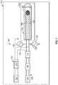
FIG. 1 is an aircraft sensor fault detection system having an alternating current source; -
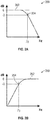
FIG. 2A is a Bode plot of frequency response for a low pass frequency filter; -
FIG. 2B is a Bode plot of frequency response for a high pass frequency filter; and -
FIG. 3 is a method for performing portions of this disclosure. - A detailed description of one or more embodiments of the disclosed apparatus and method are presented herein by way of exemplification and not limitation with reference to the Figures.
- Sensor apparatuses may be used to determine various environmental parameters. As a brief example, thermocouples and resistance temperature devices (RTD) may be used to measure a temperature of the environment. Differential pressure devices may be used to measure pressure, fluid flow, or fluid levels. Linear variable differential transformers may be used to measure position.
- A known non-destructive error detection for such devices may include application of a direct current across a sensor apparatus. The added direct current may, however, increase the error or uncertainty of the sensor apparatus for devices that measure parameter changes in the environment through direct current or that have a direct current component. As such, the direct current may be reduced, though not eliminated, to a trickle by resistors or other implements to limit the error caused.
- Additionally or alternatively, application of an alternating current through the measurement circuit may provide error identification with less impact on measurement error or uncertainty. For example, alternating current through portions of the measurement circuit may indicate corrosion, contamination, breakage, oxidation, and other error-causing operating conditions. A filter may be used to separate the direct current components from alternating current components such that parameter measurement and error measurement can be performed. For example, a high-pass or band pass frequency filter may be used to isolate the alternating current. After isolation, the alternating current may be converted to direct current through rectification and smoothing. As such, deviation from a direct current or voltage threshold could provide detection of error-causing conditions without imposing substantial measurement errors.
- Referring to
FIG. 1 , anaircraft 100, is generally shown. Theaircraft 100 includes asensor system 101. Thesensor system 101 includes asensing apparatus 102. Thesensing apparatus 102 may be athermocouple 104 or any other type of sensor, or portion thereof, discussed or not discussed. As shown, thethermocouple 104 hasdisparate conductors measurement circuit 103 connected tomeasurement instrumentation disparate conductors measurement instrumentation sensing apparatus 102, and themeasurement instrumentation disparate conductors aircraft 100. The environment may be any enclosed or open area having parameters that can be sensed. The parameter may be any property that can be determined based on thesensor apparatus 102. As a brief example, the parameter may be temperature, pressure, mass, weight, position, or velocity. - In the embodiment shown in
FIG. 1 , sources of alternating current 120 are connected to thesensor system 101. The source of alternating current 120 may be configured to flow through thesensing apparatus 102 and the rest ofmeasurement circuit 103, or a portion thereof. Thesources 120 may be phase offset to produce minimal direct current across thesensor 102. Thesources 120 may be 180° out of phase. The alternatingcurrent sources 120 may form a circuit through either themeasurement apparatus 103, the alternatingcurrent measurement apparatus 105, or both. Additionally, themeasurement apparatus 103 and the alternatingcurrent measurement apparatus 105 may be have a common ground with the alternatingcurrent sources 120. - As one connective example, the alternating current may be connected in parallel-type configuration such that alternating current flows through the sensor to the alternating current measurement system. As such, error conditions within the
sensing apparatus 102 or portions of themeasurement circuit 103 will change the alternating current that flows through such portions. Any type of series or parallel configuration may be used such that the alternating current 120 flows through portions of thesensing apparatus 102 and portion of themeasurement circuit 103. It should be appreciated that the precise position of where themeasurement circuit 103 and thesensing apparatus 102 circuits begin and end are fluid in that they may overlap, comingle, or occupy the same or similar wiring. That is, the distinction between themeasurement circuit 103 and thesensor apparatus 102 are immaterial in that portions of themeasurement circuit 103, thesensor apparatus 102 and the alternatingcurrent measurement circuit 105 overlap, comingle, and join to allow for measurement of the alternating current through a portion of themeasurement apparatus 103 and thesensor 102. - The alternating current 120 may be reduced by a
capacitor 122 such that a trickle alternating current is formed. The trickle alternating current may impose less measurement error than the full alternating current 120. In one embodiment, the trickle AC current can be applied through the outputs of thesensor 102. In the embodiment shown inFIG. 1 , this can mean that the AC current is applied through thedisparate conductors disparate conductors measurement circuit 103 changes, the alternating current through themeasurement circuit 103 and thesensor apparatus 102 will deviate from the source alternating current 120 in magnitude, phase, frequency, or any other electrical characteristic. The alternatingcurrent measurement system 105 may measure these changes to detect that a fault has occurred or that thesensing apparatus 102 ormeasurement circuit 103 has deteriorated. - To maintain accurate parameter readings of the environment the alternating current 120 is prevented from reaching the
measurement circuit 103, with afrequency filter 110. For example, a low-pass filter 110 may be implemented. The low-pass filter 110 ensures that only direct current or pseudo direct current reaches themeasurement instrumentation 112. The low pass filter may be, for example, a choke. That is, only direct current provided by the thermocouple or amplification thereof is measured by themeasurement instrumentation 112. - Similarly, the alternating
current measurement circuit 105 isolates the potentially transformed alternating current after traversing a portion of themeasurement circuit 103. The alternatingcurrent measurement system 105 includes a high-pass filter 114 for isolating the alternating current from themeasurement circuit 103. The high-pass filter may have a cutoff or corner frequency that is less than a frequency of the alternating current 120. For example, the cutoff frequency may be 1 Hz. The filter may also be a pass band filter configured to pass only frequencies associated with the alternating current 120 to remove any extraneous noise in the signal. After isolation by the high-pass filter 114, the alternating current measurement system may be configured to rectify and smooth the alternating current by a rectification and smoothingcircuit 116. For example, a full-wave rectifier may be implemented with a capacitor to convert the alternating current to direct current. Other types of rectifiers may be used (e.g., half-wave) and adjustments to the indication thresholds of thecomparator 118 may be adjusted commensurately. The thresholds may be set based on a maximum magnitude of the rectified and smoothed alternating current 102. For example, the threshold may be based on a peak value, root mean squared value, or saddle value if the smoothing does not remove all of the oscillations from the source of alternating current 102. - The
comparator 118 may include a threshold or predetermined threshold that is defined based on expected faults and errors. For example, themeasurement circuit 103 may have a static predetermined magnitude of change to the alternating current 102, and corrosion may impart known impedance to the alternating current. Using these known values, a threshold may be set to determine when corrosion or a known quantity of corrosion is occurring on thesensor apparatus 102. As such, any fault condition may be detected through observation of the affects to the alternating current signal. One or more thresholds may be used to identify the specific fault condition occurring. The thresholds may be set to identify different fault conditions that are above or below the steady state signal. - The detection of a fault may cause vehicle controllers to adjust the control of the
vehicle 100. For example, if temperatures are unreliable, an aircraft controller may operate an air conditioning system or the aircraft controller may operate the aircraft in a cautious mode. - Referring to
FIGs. 2A-2B , Bode plots 200, 250 showing frequency response for respective low pass and high pass frequency filters are shown.Bode plot 200 includes acontour 202 of allowed frequencies in Hz along the horizontal axis. TheBode plot 200 shows power reduction of -3 dB at the corner orcutoff frequency 204 along the vertical axis. Thecutoff frequency 204 is the division between the pass frequencies and the stop frequencies. The cutoff frequency for the low pass frequency filter as shown inBode plot 200 could be 1 Hz.Bode plot 250 includes acontour 252 of allowed frequencies in Hz along the horizontal axis. TheBode plot 200 shows power reduction of -3 dB at the corner orcutoff frequency 254 along the vertical axis. The cutoff frequency for the high pass frequency filter as shown inBode plot 250 could similarly be 1 Hz. The pass frequency may also be a band (not shown) as a concave combination of the high pass and low pass frequency filters. - Referring to
FIG. 3 , amethod 300 is shown. Themethod 300 starts instep 302. Instep 304, current is driven through thesensing system 101 including thesensing apparatus 102. Instep 306, the direct current is separated from the alternating current by afilter 114. Instep 308, the alternating current is rectified by arectifier 116. Instep 310, a controller, operational amplifier, comparator, or other implement of the alternatingcurrent measurement system 105 determines whether the rectified alternating current is above the predetermined threshold. Instep 312, if true, an output condition is presented to an operator or control system to indicate an error. Instep 314, the aircraft is operated according to error. - The term "about" is intended to include the degree of error associated with measurement of the particular quantity based upon the equipment available at the time of filing the application.
- The terminology used herein is for the purpose of describing particular embodiments only and is not intended to be limiting of the present disclosure. As used herein, the singular forms "a", "an" and "the" are intended to include the plural forms as well, unless the context clearly indicates otherwise. It will be further understood that the terms "comprises" and/or "comprising," when used in this specification, specify the presence of stated features, integers, steps, operations, elements, and/or components, but do not preclude the presence or addition of one or more other features, integers, steps, operations, element components, and/or groups thereof.
- While the present disclosure has been described with reference to an exemplary embodiment or embodiments, it will be understood by those skilled in the art that various changes may be made and equivalents may be substituted for elements thereof without departing from the scope of the present disclosure. In addition, many modifications may be made to adapt a particular situation or material to the teachings of the present disclosure without departing from the essential scope thereof. Therefore, it is intended that the present disclosure not be limited to the particular embodiment disclosed as the best mode contemplated for carrying out this present disclosure, but that the present disclosure will include all embodiments falling within the scope of the claims.
Claims (15)
- An aircraft sensor fault detection system, the system comprising:a sensor system (101) including a sensing apparatus (102) to measure a parameter of an environment and a measurement circuit coupled to the sensing apparatus;a source of alternating current (120) connected to the sensor system; andan alternating current measurement system (105) thatmeasures alternating current from the source passing through the sensor system, andindicates an error when a threshold based on a change in impedance of the sensing apparatus is exceeded.
- The aircraft sensor fault detection system of claim 1, wherein the source of alternating current is reduced by a capacitor (122) before passing through the sensor system.
- The aircraft sensor fault detection system of any preceding claim, wherein the alternating current measurement system includes a high pass frequency filter (114) having a cutoff frequency that is less than a frequency of alternating current from the source; optionally wherein the cutoff frequency is 1 Hz.
- The aircraft sensor fault detection system of any preceding claim, wherein the alternating current measurement system further includes a rectifier disposed to rectify alternating current from the source.
- The aircraft sensor fault detection system of any preceding claim, wherein the error is indicated when a maximum magnitude of the rectified alternating current is greater than the predetermined magnitude; or wherein the error is indicated when a maximum magnitude of the rectified alternating current is less than the predetermined magnitude.
- The aircraft sensor fault detection system of any preceding claim, wherein the sensing apparatus is a thermocouple.
- The aircraft sensor fault detection system of any preceding claim, wherein the threshold is based on a predetermined magnitude of alternating current from the source passing through the sensor system.
- The aircraft sensor fault detection system, according to any of claims 1 to 4; wherein
the sensor system (101) includes a thermocouple (104) to measure a temperature of the environment and the measurement circuit is coupled to the thermocouple to measure a direct voltage generated by the thermocouple;
wherein the alternating current measurement system
measures alternating current from the source passing through the sensor system as a rectified and smoothed direct current isolated from the direct voltage generated by the thermocouple. - The aircraft sensor fault detection system of claim 8, wherein the threshold is based on a predetermined maximum magnitude of alternating current passing through the sensor system.
- The aircraft sensor fault detection system of claim 9, wherein the error is indicated when a maximum magnitude of the rectified alternating current is greater than the predetermined maximum magnitude.
- The aircraft sensor fault detection system of claim 9, wherein the error is indicated when a maximum magnitude of the rectified alternating current is less than the predetermined maximum magnitude.
- A method of detecting a fault in an aircraft sensor system, the method comprising:driving (304) an alternating current through a sensing system (101) including a sensing apparatus (102) measuring a parameter of an environment and a measurement circuit coupled to the sensing apparatus;separating (306) a direct current associated with the sensing system from the alternating current;rectifying (308) the alternating current;comparing (310) a feature of the rectified alternating current with a predetermined threshold based on the alternating current;outputting (312) an error based on the comparison; andoperating (314) an aircraft according to the error.
- The method of claim 12, wherein the feature is a maximum magnitude of the rectified alternating current.
- The method of claim 12 or 13 further comprising, reducing the alternating current by a capacitor (122) before entering the sensing system.
- The method of claim 12, 13 or 14 further comprising smoothing the rectified alternating current.
Applications Claiming Priority (1)
| Application Number | Priority Date | Filing Date | Title |
|---|---|---|---|
| US16/373,180 US11112444B2 (en) | 2019-04-02 | 2019-04-02 | Reduced error sensor fault detection |
Publications (2)
| Publication Number | Publication Date |
|---|---|
| EP3719464A1 true EP3719464A1 (en) | 2020-10-07 |
| EP3719464B1 EP3719464B1 (en) | 2023-04-05 |
Family
ID=68762583
Family Applications (1)
| Application Number | Title | Priority Date | Filing Date |
|---|---|---|---|
| EP19212843.7A Active EP3719464B1 (en) | 2019-04-02 | 2019-12-02 | Reduced error sensor fault detection |
Country Status (2)
| Country | Link |
|---|---|
| US (1) | US11112444B2 (en) |
| EP (1) | EP3719464B1 (en) |
Cited By (1)
| Publication number | Priority date | Publication date | Assignee | Title |
|---|---|---|---|---|
| US20220334002A1 (en) * | 2019-06-03 | 2022-10-20 | Daily Thermetrics Corporation | Temperature sensor and methods of use |
Families Citing this family (3)
| Publication number | Priority date | Publication date | Assignee | Title |
|---|---|---|---|---|
| CN114296018B (en) * | 2020-12-16 | 2025-04-22 | 华为数字能源技术有限公司 | Sensor fault detection circuit, fault detection method and electric vehicle |
| DE102023107326A1 (en) * | 2023-03-23 | 2024-09-26 | Deutsches Zentrum für Luft- und Raumfahrt e.V. | Identifying a failure of a sensor-based air data system |
| CN117890715A (en) * | 2024-03-14 | 2024-04-16 | 大连海事大学 | Filter electrical performance test system based on big data information analysis |
Citations (3)
| Publication number | Priority date | Publication date | Assignee | Title |
|---|---|---|---|---|
| JPH0548153A (en) * | 1991-08-09 | 1993-02-26 | Hioki Ee Corp | Burnout detection circuit for thermocouple thermometer |
| GB2498370A (en) * | 2012-01-12 | 2013-07-17 | Rolls Royce Engine Control Systems Ltd | Thermocouple fault detection |
| EP3385681A1 (en) * | 2017-04-07 | 2018-10-10 | Hamilton Sundstrand Corporation | Alternating current coupled open circuit detection for low level direct current analog interfaces |
Family Cites Families (7)
| Publication number | Priority date | Publication date | Assignee | Title |
|---|---|---|---|---|
| JP4749132B2 (en) | 2005-11-21 | 2011-08-17 | 富士通セミコンダクター株式会社 | Sensor detection device and sensor |
| EP2710388B1 (en) * | 2011-05-20 | 2021-05-19 | SMA Solar Technology AG | Method and system for detecting an arc fault in a power circuit |
| US8599523B1 (en) * | 2011-07-29 | 2013-12-03 | Leviton Manufacturing Company, Inc. | Arc fault circuit interrupter |
| GB201120295D0 (en) * | 2011-11-24 | 2012-01-04 | Metroic Ltd | Current measurement apparatus |
| US10075065B2 (en) * | 2016-04-15 | 2018-09-11 | Emerson Climate Technologies, Inc. | Choke and EMI filter circuits for power factor correction circuits |
| US10132846B2 (en) * | 2016-06-14 | 2018-11-20 | Analog Devices Global | Method of and apparatus for learning the phase error or timing delays within a current transducer and power measurement apparatus including current transducer error correction |
| GB2571551B (en) * | 2018-03-01 | 2021-03-03 | Ge Aviat Systems Ltd | System and method for detecting arc faults |
-
2019
- 2019-04-02 US US16/373,180 patent/US11112444B2/en active Active
- 2019-12-02 EP EP19212843.7A patent/EP3719464B1/en active Active
Patent Citations (3)
| Publication number | Priority date | Publication date | Assignee | Title |
|---|---|---|---|---|
| JPH0548153A (en) * | 1991-08-09 | 1993-02-26 | Hioki Ee Corp | Burnout detection circuit for thermocouple thermometer |
| GB2498370A (en) * | 2012-01-12 | 2013-07-17 | Rolls Royce Engine Control Systems Ltd | Thermocouple fault detection |
| EP3385681A1 (en) * | 2017-04-07 | 2018-10-10 | Hamilton Sundstrand Corporation | Alternating current coupled open circuit detection for low level direct current analog interfaces |
Cited By (2)
| Publication number | Priority date | Publication date | Assignee | Title |
|---|---|---|---|---|
| US20220334002A1 (en) * | 2019-06-03 | 2022-10-20 | Daily Thermetrics Corporation | Temperature sensor and methods of use |
| US11747214B2 (en) * | 2019-06-03 | 2023-09-05 | Daily Thermetrics Corporation | Temperature sensor and methods of use |
Also Published As
| Publication number | Publication date |
|---|---|
| US11112444B2 (en) | 2021-09-07 |
| EP3719464B1 (en) | 2023-04-05 |
| US20200319238A1 (en) | 2020-10-08 |
Similar Documents
| Publication | Publication Date | Title |
|---|---|---|
| EP3719464B1 (en) | Reduced error sensor fault detection | |
| CN101881791B (en) | Voltage detection device | |
| US10353004B2 (en) | Method and system for detecting rotor fault using triaxial magnetic field sensor | |
| CN101479562B (en) | Vibration and condition monitoring system and the parts thereof | |
| EP2902793B1 (en) | Method and device for off-line testing of electric motors | |
| EP3143418B1 (en) | Method and system for detecting rotor fault | |
| EP1423715B1 (en) | Diagnostics for piezoelectric sensor | |
| EP3385681A1 (en) | Alternating current coupled open circuit detection for low level direct current analog interfaces | |
| JP6476111B2 (en) | Process control loop current verification | |
| CN216160806U (en) | A neutral wire disconnection detection module and an electrical fire early warning system | |
| US7233464B2 (en) | Apparatus for and method of ground fault detection | |
| US11047920B2 (en) | Sensor to sensor short detection | |
| CN212409611U (en) | Steel wire surface zinc layer thickness detection sensor based on eddy current detection | |
| CN113625193A (en) | An electrical fire warning system that can identify a variety of electrical hidden dangers | |
| US20200036321A1 (en) | Motor controller and motor control method | |
| US2605304A (en) | Electric motor load indicator | |
| RU2654996C1 (en) | Device for equipment diagnostics (measuring channel) | |
| KR101679520B1 (en) | The defect's the width of a pipe measurement system using multi channel RFECT and measurement method using the same | |
| CN104237620B (en) | voltage detection device | |
| CN212988621U (en) | Motor temperature detection device | |
| JPS61137081A (en) | Failed point positioning apparatus of dc transmitting system | |
| US10288648B2 (en) | Remote sensing system | |
| JPH04181125A (en) | Vibration monitoring device | |
| JPH03128692A (en) | Protective device for motor | |
| JPH0652205B2 (en) | Load fluctuation detection method and device |
Legal Events
| Date | Code | Title | Description |
|---|---|---|---|
| PUAI | Public reference made under article 153(3) epc to a published international application that has entered the european phase |
Free format text: ORIGINAL CODE: 0009012 |
|
| STAA | Information on the status of an ep patent application or granted ep patent |
Free format text: STATUS: THE APPLICATION HAS BEEN PUBLISHED |
|
| AK | Designated contracting states |
Kind code of ref document: A1 Designated state(s): AL AT BE BG CH CY CZ DE DK EE ES FI FR GB GR HR HU IE IS IT LI LT LU LV MC MK MT NL NO PL PT RO RS SE SI SK SM TR |
|
| AX | Request for extension of the european patent |
Extension state: BA ME |
|
| STAA | Information on the status of an ep patent application or granted ep patent |
Free format text: STATUS: REQUEST FOR EXAMINATION WAS MADE |
|
| 17P | Request for examination filed |
Effective date: 20210407 |
|
| RBV | Designated contracting states (corrected) |
Designated state(s): AL AT BE BG CH CY CZ DE DK EE ES FI FR GB GR HR HU IE IS IT LI LT LU LV MC MK MT NL NO PL PT RO RS SE SI SK SM TR |
|
| REG | Reference to a national code |
Ref country code: DE Ref legal event code: R079 Ref document number: 602019027139 Country of ref document: DE Free format text: PREVIOUS MAIN CLASS: G01K0007020000 Ipc: G01K0007026000 |
|
| RIC1 | Information provided on ipc code assigned before grant |
Ipc: G01D 3/08 20060101ALI20220927BHEP Ipc: G01K 15/00 20060101ALI20220927BHEP Ipc: G01K 7/026 20210101AFI20220927BHEP |
|
| GRAP | Despatch of communication of intention to grant a patent |
Free format text: ORIGINAL CODE: EPIDOSNIGR1 |
|
| STAA | Information on the status of an ep patent application or granted ep patent |
Free format text: STATUS: GRANT OF PATENT IS INTENDED |
|
| INTG | Intention to grant announced |
Effective date: 20221115 |
|
| GRAS | Grant fee paid |
Free format text: ORIGINAL CODE: EPIDOSNIGR3 |
|
| GRAA | (expected) grant |
Free format text: ORIGINAL CODE: 0009210 |
|
| STAA | Information on the status of an ep patent application or granted ep patent |
Free format text: STATUS: THE PATENT HAS BEEN GRANTED |
|
| AK | Designated contracting states |
Kind code of ref document: B1 Designated state(s): AL AT BE BG CH CY CZ DE DK EE ES FI FR GB GR HR HU IE IS IT LI LT LU LV MC MK MT NL NO PL PT RO RS SE SI SK SM TR |
|
| REG | Reference to a national code |
Ref country code: GB Ref legal event code: FG4D |
|
| REG | Reference to a national code |
Ref country code: CH Ref legal event code: EP |
|
| REG | Reference to a national code |
Ref country code: AT Ref legal event code: REF Ref document number: 1558560 Country of ref document: AT Kind code of ref document: T Effective date: 20230415 |
|
| REG | Reference to a national code |
Ref country code: DE Ref legal event code: R096 Ref document number: 602019027139 Country of ref document: DE |
|
| REG | Reference to a national code |
Ref country code: IE Ref legal event code: FG4D |
|
| P01 | Opt-out of the competence of the unified patent court (upc) registered |
Effective date: 20230603 |
|
| REG | Reference to a national code |
Ref country code: LT Ref legal event code: MG9D |
|
| REG | Reference to a national code |
Ref country code: NL Ref legal event code: MP Effective date: 20230405 |
|
| REG | Reference to a national code |
Ref country code: AT Ref legal event code: MK05 Ref document number: 1558560 Country of ref document: AT Kind code of ref document: T Effective date: 20230405 |
|
| PG25 | Lapsed in a contracting state [announced via postgrant information from national office to epo] |
Ref country code: NL Free format text: LAPSE BECAUSE OF FAILURE TO SUBMIT A TRANSLATION OF THE DESCRIPTION OR TO PAY THE FEE WITHIN THE PRESCRIBED TIME-LIMIT Effective date: 20230405 |
|
| PG25 | Lapsed in a contracting state [announced via postgrant information from national office to epo] |
Ref country code: SE Free format text: LAPSE BECAUSE OF FAILURE TO SUBMIT A TRANSLATION OF THE DESCRIPTION OR TO PAY THE FEE WITHIN THE PRESCRIBED TIME-LIMIT Effective date: 20230405 Ref country code: PT Free format text: LAPSE BECAUSE OF FAILURE TO SUBMIT A TRANSLATION OF THE DESCRIPTION OR TO PAY THE FEE WITHIN THE PRESCRIBED TIME-LIMIT Effective date: 20230807 Ref country code: NO Free format text: LAPSE BECAUSE OF FAILURE TO SUBMIT A TRANSLATION OF THE DESCRIPTION OR TO PAY THE FEE WITHIN THE PRESCRIBED TIME-LIMIT Effective date: 20230705 Ref country code: ES Free format text: LAPSE BECAUSE OF FAILURE TO SUBMIT A TRANSLATION OF THE DESCRIPTION OR TO PAY THE FEE WITHIN THE PRESCRIBED TIME-LIMIT Effective date: 20230405 Ref country code: AT Free format text: LAPSE BECAUSE OF FAILURE TO SUBMIT A TRANSLATION OF THE DESCRIPTION OR TO PAY THE FEE WITHIN THE PRESCRIBED TIME-LIMIT Effective date: 20230405 |
|
| PG25 | Lapsed in a contracting state [announced via postgrant information from national office to epo] |
Ref country code: RS Free format text: LAPSE BECAUSE OF FAILURE TO SUBMIT A TRANSLATION OF THE DESCRIPTION OR TO PAY THE FEE WITHIN THE PRESCRIBED TIME-LIMIT Effective date: 20230405 Ref country code: PL Free format text: LAPSE BECAUSE OF FAILURE TO SUBMIT A TRANSLATION OF THE DESCRIPTION OR TO PAY THE FEE WITHIN THE PRESCRIBED TIME-LIMIT Effective date: 20230405 Ref country code: LV Free format text: LAPSE BECAUSE OF FAILURE TO SUBMIT A TRANSLATION OF THE DESCRIPTION OR TO PAY THE FEE WITHIN THE PRESCRIBED TIME-LIMIT Effective date: 20230405 Ref country code: LT Free format text: LAPSE BECAUSE OF FAILURE TO SUBMIT A TRANSLATION OF THE DESCRIPTION OR TO PAY THE FEE WITHIN THE PRESCRIBED TIME-LIMIT Effective date: 20230405 Ref country code: IS Free format text: LAPSE BECAUSE OF FAILURE TO SUBMIT A TRANSLATION OF THE DESCRIPTION OR TO PAY THE FEE WITHIN THE PRESCRIBED TIME-LIMIT Effective date: 20230805 Ref country code: HR Free format text: LAPSE BECAUSE OF FAILURE TO SUBMIT A TRANSLATION OF THE DESCRIPTION OR TO PAY THE FEE WITHIN THE PRESCRIBED TIME-LIMIT Effective date: 20230405 Ref country code: GR Free format text: LAPSE BECAUSE OF FAILURE TO SUBMIT A TRANSLATION OF THE DESCRIPTION OR TO PAY THE FEE WITHIN THE PRESCRIBED TIME-LIMIT Effective date: 20230706 Ref country code: AL Free format text: LAPSE BECAUSE OF FAILURE TO SUBMIT A TRANSLATION OF THE DESCRIPTION OR TO PAY THE FEE WITHIN THE PRESCRIBED TIME-LIMIT Effective date: 20230405 |
|
| PG25 | Lapsed in a contracting state [announced via postgrant information from national office to epo] |
Ref country code: FI Free format text: LAPSE BECAUSE OF FAILURE TO SUBMIT A TRANSLATION OF THE DESCRIPTION OR TO PAY THE FEE WITHIN THE PRESCRIBED TIME-LIMIT Effective date: 20230405 |
|
| REG | Reference to a national code |
Ref country code: DE Ref legal event code: R097 Ref document number: 602019027139 Country of ref document: DE |
|
| PG25 | Lapsed in a contracting state [announced via postgrant information from national office to epo] |
Ref country code: SK Free format text: LAPSE BECAUSE OF FAILURE TO SUBMIT A TRANSLATION OF THE DESCRIPTION OR TO PAY THE FEE WITHIN THE PRESCRIBED TIME-LIMIT Effective date: 20230405 |
|
| PG25 | Lapsed in a contracting state [announced via postgrant information from national office to epo] |
Ref country code: SM Free format text: LAPSE BECAUSE OF FAILURE TO SUBMIT A TRANSLATION OF THE DESCRIPTION OR TO PAY THE FEE WITHIN THE PRESCRIBED TIME-LIMIT Effective date: 20230405 Ref country code: SK Free format text: LAPSE BECAUSE OF FAILURE TO SUBMIT A TRANSLATION OF THE DESCRIPTION OR TO PAY THE FEE WITHIN THE PRESCRIBED TIME-LIMIT Effective date: 20230405 Ref country code: RO Free format text: LAPSE BECAUSE OF FAILURE TO SUBMIT A TRANSLATION OF THE DESCRIPTION OR TO PAY THE FEE WITHIN THE PRESCRIBED TIME-LIMIT Effective date: 20230405 Ref country code: EE Free format text: LAPSE BECAUSE OF FAILURE TO SUBMIT A TRANSLATION OF THE DESCRIPTION OR TO PAY THE FEE WITHIN THE PRESCRIBED TIME-LIMIT Effective date: 20230405 Ref country code: DK Free format text: LAPSE BECAUSE OF FAILURE TO SUBMIT A TRANSLATION OF THE DESCRIPTION OR TO PAY THE FEE WITHIN THE PRESCRIBED TIME-LIMIT Effective date: 20230405 Ref country code: CZ Free format text: LAPSE BECAUSE OF FAILURE TO SUBMIT A TRANSLATION OF THE DESCRIPTION OR TO PAY THE FEE WITHIN THE PRESCRIBED TIME-LIMIT Effective date: 20230405 |
|
| PLBE | No opposition filed within time limit |
Free format text: ORIGINAL CODE: 0009261 |
|
| STAA | Information on the status of an ep patent application or granted ep patent |
Free format text: STATUS: NO OPPOSITION FILED WITHIN TIME LIMIT |
|
| 26N | No opposition filed |
Effective date: 20240108 |
|
| PG25 | Lapsed in a contracting state [announced via postgrant information from national office to epo] |
Ref country code: SI Free format text: LAPSE BECAUSE OF FAILURE TO SUBMIT A TRANSLATION OF THE DESCRIPTION OR TO PAY THE FEE WITHIN THE PRESCRIBED TIME-LIMIT Effective date: 20230405 |
|
| PG25 | Lapsed in a contracting state [announced via postgrant information from national office to epo] |
Ref country code: SI Free format text: LAPSE BECAUSE OF FAILURE TO SUBMIT A TRANSLATION OF THE DESCRIPTION OR TO PAY THE FEE WITHIN THE PRESCRIBED TIME-LIMIT Effective date: 20230405 Ref country code: IT Free format text: LAPSE BECAUSE OF FAILURE TO SUBMIT A TRANSLATION OF THE DESCRIPTION OR TO PAY THE FEE WITHIN THE PRESCRIBED TIME-LIMIT Effective date: 20230405 |
|
| REG | Reference to a national code |
Ref country code: CH Ref legal event code: PL |
|
| PG25 | Lapsed in a contracting state [announced via postgrant information from national office to epo] |
Ref country code: LU Free format text: LAPSE BECAUSE OF NON-PAYMENT OF DUE FEES Effective date: 20231202 |
|
| PG25 | Lapsed in a contracting state [announced via postgrant information from national office to epo] |
Ref country code: MC Free format text: LAPSE BECAUSE OF FAILURE TO SUBMIT A TRANSLATION OF THE DESCRIPTION OR TO PAY THE FEE WITHIN THE PRESCRIBED TIME-LIMIT Effective date: 20230405 |
|
| REG | Reference to a national code |
Ref country code: BE Ref legal event code: MM Effective date: 20231231 |
|
| PG25 | Lapsed in a contracting state [announced via postgrant information from national office to epo] |
Ref country code: MC Free format text: LAPSE BECAUSE OF FAILURE TO SUBMIT A TRANSLATION OF THE DESCRIPTION OR TO PAY THE FEE WITHIN THE PRESCRIBED TIME-LIMIT Effective date: 20230405 Ref country code: LU Free format text: LAPSE BECAUSE OF NON-PAYMENT OF DUE FEES Effective date: 20231202 |
|
| REG | Reference to a national code |
Ref country code: IE Ref legal event code: MM4A |
|
| PG25 | Lapsed in a contracting state [announced via postgrant information from national office to epo] |
Ref country code: IE Free format text: LAPSE BECAUSE OF NON-PAYMENT OF DUE FEES Effective date: 20231202 |
|
| PG25 | Lapsed in a contracting state [announced via postgrant information from national office to epo] |
Ref country code: BE Free format text: LAPSE BECAUSE OF NON-PAYMENT OF DUE FEES Effective date: 20231231 |
|
| PG25 | Lapsed in a contracting state [announced via postgrant information from national office to epo] |
Ref country code: CH Free format text: LAPSE BECAUSE OF NON-PAYMENT OF DUE FEES Effective date: 20231231 |
|
| PG25 | Lapsed in a contracting state [announced via postgrant information from national office to epo] |
Ref country code: IE Free format text: LAPSE BECAUSE OF NON-PAYMENT OF DUE FEES Effective date: 20231202 Ref country code: CH Free format text: LAPSE BECAUSE OF NON-PAYMENT OF DUE FEES Effective date: 20231231 Ref country code: BE Free format text: LAPSE BECAUSE OF NON-PAYMENT OF DUE FEES Effective date: 20231231 |
|
| PG25 | Lapsed in a contracting state [announced via postgrant information from national office to epo] |
Ref country code: BG Free format text: LAPSE BECAUSE OF FAILURE TO SUBMIT A TRANSLATION OF THE DESCRIPTION OR TO PAY THE FEE WITHIN THE PRESCRIBED TIME-LIMIT Effective date: 20230405 |
|
| PG25 | Lapsed in a contracting state [announced via postgrant information from national office to epo] |
Ref country code: BG Free format text: LAPSE BECAUSE OF FAILURE TO SUBMIT A TRANSLATION OF THE DESCRIPTION OR TO PAY THE FEE WITHIN THE PRESCRIBED TIME-LIMIT Effective date: 20230405 |
|
| PG25 | Lapsed in a contracting state [announced via postgrant information from national office to epo] |
Ref country code: CY Free format text: LAPSE BECAUSE OF FAILURE TO SUBMIT A TRANSLATION OF THE DESCRIPTION OR TO PAY THE FEE WITHIN THE PRESCRIBED TIME-LIMIT; INVALID AB INITIO Effective date: 20191202 |
|
| PG25 | Lapsed in a contracting state [announced via postgrant information from national office to epo] |
Ref country code: HU Free format text: LAPSE BECAUSE OF FAILURE TO SUBMIT A TRANSLATION OF THE DESCRIPTION OR TO PAY THE FEE WITHIN THE PRESCRIBED TIME-LIMIT; INVALID AB INITIO Effective date: 20191202 |
|
| PG25 | Lapsed in a contracting state [announced via postgrant information from national office to epo] |
Ref country code: TR Free format text: LAPSE BECAUSE OF FAILURE TO SUBMIT A TRANSLATION OF THE DESCRIPTION OR TO PAY THE FEE WITHIN THE PRESCRIBED TIME-LIMIT Effective date: 20230405 |
|
| PGFP | Annual fee paid to national office [announced via postgrant information from national office to epo] |
Ref country code: DE Payment date: 20251126 Year of fee payment: 7 |
|
| PGFP | Annual fee paid to national office [announced via postgrant information from national office to epo] |
Ref country code: GB Payment date: 20251120 Year of fee payment: 7 |
|
| PGFP | Annual fee paid to national office [announced via postgrant information from national office to epo] |
Ref country code: FR Payment date: 20251120 Year of fee payment: 7 |