EP3719420A1 - Air conditioning system and control method thereof - Google Patents
Air conditioning system and control method thereof Download PDFInfo
- Publication number
- EP3719420A1 EP3719420A1 EP20165873.9A EP20165873A EP3719420A1 EP 3719420 A1 EP3719420 A1 EP 3719420A1 EP 20165873 A EP20165873 A EP 20165873A EP 3719420 A1 EP3719420 A1 EP 3719420A1
- Authority
- EP
- European Patent Office
- Prior art keywords
- thermal
- temperature sensing
- sensing bulb
- air conditioning
- conditioning system
- Prior art date
- Legal status (The legal status is an assumption and is not a legal conclusion. Google has not performed a legal analysis and makes no representation as to the accuracy of the status listed.)
- Ceased
Links
Images
Classifications
-
- F—MECHANICAL ENGINEERING; LIGHTING; HEATING; WEAPONS; BLASTING
- F24—HEATING; RANGES; VENTILATING
- F24F—AIR-CONDITIONING; AIR-HUMIDIFICATION; VENTILATION; USE OF AIR CURRENTS FOR SCREENING
- F24F11/00—Control or safety arrangements
- F24F11/70—Control systems characterised by their outputs; Constructional details thereof
- F24F11/80—Control systems characterised by their outputs; Constructional details thereof for controlling the temperature of the supplied air
- F24F11/83—Control systems characterised by their outputs; Constructional details thereof for controlling the temperature of the supplied air by controlling the supply of heat-exchange fluids to heat-exchangers
- F24F11/84—Control systems characterised by their outputs; Constructional details thereof for controlling the temperature of the supplied air by controlling the supply of heat-exchange fluids to heat-exchangers using valves
-
- F—MECHANICAL ENGINEERING; LIGHTING; HEATING; WEAPONS; BLASTING
- F25—REFRIGERATION OR COOLING; COMBINED HEATING AND REFRIGERATION SYSTEMS; HEAT PUMP SYSTEMS; MANUFACTURE OR STORAGE OF ICE; LIQUEFACTION SOLIDIFICATION OF GASES
- F25B—REFRIGERATION MACHINES, PLANTS OR SYSTEMS; COMBINED HEATING AND REFRIGERATION SYSTEMS; HEAT PUMP SYSTEMS
- F25B49/00—Arrangement or mounting of control or safety devices
- F25B49/02—Arrangement or mounting of control or safety devices for compression type machines, plants or systems
-
- F—MECHANICAL ENGINEERING; LIGHTING; HEATING; WEAPONS; BLASTING
- F24—HEATING; RANGES; VENTILATING
- F24F—AIR-CONDITIONING; AIR-HUMIDIFICATION; VENTILATION; USE OF AIR CURRENTS FOR SCREENING
- F24F2140/00—Control inputs relating to system states
- F24F2140/20—Heat-exchange fluid temperature
-
- F—MECHANICAL ENGINEERING; LIGHTING; HEATING; WEAPONS; BLASTING
- F25—REFRIGERATION OR COOLING; COMBINED HEATING AND REFRIGERATION SYSTEMS; HEAT PUMP SYSTEMS; MANUFACTURE OR STORAGE OF ICE; LIQUEFACTION SOLIDIFICATION OF GASES
- F25B—REFRIGERATION MACHINES, PLANTS OR SYSTEMS; COMBINED HEATING AND REFRIGERATION SYSTEMS; HEAT PUMP SYSTEMS
- F25B2341/00—Details of ejectors not being used as compression device; Details of flow restrictors or expansion valves
- F25B2341/06—Details of flow restrictors or expansion valves
-
- F—MECHANICAL ENGINEERING; LIGHTING; HEATING; WEAPONS; BLASTING
- F25—REFRIGERATION OR COOLING; COMBINED HEATING AND REFRIGERATION SYSTEMS; HEAT PUMP SYSTEMS; MANUFACTURE OR STORAGE OF ICE; LIQUEFACTION SOLIDIFICATION OF GASES
- F25B—REFRIGERATION MACHINES, PLANTS OR SYSTEMS; COMBINED HEATING AND REFRIGERATION SYSTEMS; HEAT PUMP SYSTEMS
- F25B2341/00—Details of ejectors not being used as compression device; Details of flow restrictors or expansion valves
- F25B2341/06—Details of flow restrictors or expansion valves
- F25B2341/064—Superheater expansion valves
-
- F—MECHANICAL ENGINEERING; LIGHTING; HEATING; WEAPONS; BLASTING
- F25—REFRIGERATION OR COOLING; COMBINED HEATING AND REFRIGERATION SYSTEMS; HEAT PUMP SYSTEMS; MANUFACTURE OR STORAGE OF ICE; LIQUEFACTION SOLIDIFICATION OF GASES
- F25B—REFRIGERATION MACHINES, PLANTS OR SYSTEMS; COMBINED HEATING AND REFRIGERATION SYSTEMS; HEAT PUMP SYSTEMS
- F25B2341/00—Details of ejectors not being used as compression device; Details of flow restrictors or expansion valves
- F25B2341/06—Details of flow restrictors or expansion valves
- F25B2341/068—Expansion valves combined with a sensor
- F25B2341/0681—Expansion valves combined with a sensor the sensor is heated
-
- F—MECHANICAL ENGINEERING; LIGHTING; HEATING; WEAPONS; BLASTING
- F25—REFRIGERATION OR COOLING; COMBINED HEATING AND REFRIGERATION SYSTEMS; HEAT PUMP SYSTEMS; MANUFACTURE OR STORAGE OF ICE; LIQUEFACTION SOLIDIFICATION OF GASES
- F25B—REFRIGERATION MACHINES, PLANTS OR SYSTEMS; COMBINED HEATING AND REFRIGERATION SYSTEMS; HEAT PUMP SYSTEMS
- F25B2400/00—Component parts or details not otherwise provided for in this subclass
- F25B2400/07—Details of compressors or related parts
- F25B2400/077—Compressor control units, e.g. terminal boxes, mounted on the compressor casing wall containing for example starter, protection switches or connector contacts
-
- F—MECHANICAL ENGINEERING; LIGHTING; HEATING; WEAPONS; BLASTING
- F25—REFRIGERATION OR COOLING; COMBINED HEATING AND REFRIGERATION SYSTEMS; HEAT PUMP SYSTEMS; MANUFACTURE OR STORAGE OF ICE; LIQUEFACTION SOLIDIFICATION OF GASES
- F25B—REFRIGERATION MACHINES, PLANTS OR SYSTEMS; COMBINED HEATING AND REFRIGERATION SYSTEMS; HEAT PUMP SYSTEMS
- F25B2500/00—Problems to be solved
- F25B2500/15—Hunting, i.e. oscillation of controlled refrigeration variables reaching undesirable values
-
- F—MECHANICAL ENGINEERING; LIGHTING; HEATING; WEAPONS; BLASTING
- F25—REFRIGERATION OR COOLING; COMBINED HEATING AND REFRIGERATION SYSTEMS; HEAT PUMP SYSTEMS; MANUFACTURE OR STORAGE OF ICE; LIQUEFACTION SOLIDIFICATION OF GASES
- F25B—REFRIGERATION MACHINES, PLANTS OR SYSTEMS; COMBINED HEATING AND REFRIGERATION SYSTEMS; HEAT PUMP SYSTEMS
- F25B2500/00—Problems to be solved
- F25B2500/26—Problems to be solved characterised by the startup of the refrigeration cycle
-
- F—MECHANICAL ENGINEERING; LIGHTING; HEATING; WEAPONS; BLASTING
- F25—REFRIGERATION OR COOLING; COMBINED HEATING AND REFRIGERATION SYSTEMS; HEAT PUMP SYSTEMS; MANUFACTURE OR STORAGE OF ICE; LIQUEFACTION SOLIDIFICATION OF GASES
- F25B—REFRIGERATION MACHINES, PLANTS OR SYSTEMS; COMBINED HEATING AND REFRIGERATION SYSTEMS; HEAT PUMP SYSTEMS
- F25B2600/00—Control issues
- F25B2600/01—Timing
-
- F—MECHANICAL ENGINEERING; LIGHTING; HEATING; WEAPONS; BLASTING
- F25—REFRIGERATION OR COOLING; COMBINED HEATING AND REFRIGERATION SYSTEMS; HEAT PUMP SYSTEMS; MANUFACTURE OR STORAGE OF ICE; LIQUEFACTION SOLIDIFICATION OF GASES
- F25B—REFRIGERATION MACHINES, PLANTS OR SYSTEMS; COMBINED HEATING AND REFRIGERATION SYSTEMS; HEAT PUMP SYSTEMS
- F25B2600/00—Control issues
- F25B2600/25—Control of valves
- F25B2600/2513—Expansion valves
-
- F—MECHANICAL ENGINEERING; LIGHTING; HEATING; WEAPONS; BLASTING
- F25—REFRIGERATION OR COOLING; COMBINED HEATING AND REFRIGERATION SYSTEMS; HEAT PUMP SYSTEMS; MANUFACTURE OR STORAGE OF ICE; LIQUEFACTION SOLIDIFICATION OF GASES
- F25B—REFRIGERATION MACHINES, PLANTS OR SYSTEMS; COMBINED HEATING AND REFRIGERATION SYSTEMS; HEAT PUMP SYSTEMS
- F25B2700/00—Sensing or detecting of parameters; Sensors therefor
- F25B2700/21—Temperatures
- F25B2700/2117—Temperatures of an evaporator
- F25B2700/21175—Temperatures of an evaporator of the refrigerant at the outlet of the evaporator
-
- F—MECHANICAL ENGINEERING; LIGHTING; HEATING; WEAPONS; BLASTING
- F25—REFRIGERATION OR COOLING; COMBINED HEATING AND REFRIGERATION SYSTEMS; HEAT PUMP SYSTEMS; MANUFACTURE OR STORAGE OF ICE; LIQUEFACTION SOLIDIFICATION OF GASES
- F25B—REFRIGERATION MACHINES, PLANTS OR SYSTEMS; COMBINED HEATING AND REFRIGERATION SYSTEMS; HEAT PUMP SYSTEMS
- F25B41/00—Fluid-circulation arrangements
- F25B41/30—Expansion means; Dispositions thereof
- F25B41/31—Expansion valves
- F25B41/33—Expansion valves with the valve member being actuated by the fluid pressure, e.g. by the pressure of the refrigerant
Definitions
- the present invention relates to an air conditioning system and a control method of an air conditioning system, and in particular to a startup control of an air conditioning system.
- a cyclic degradation coefficient is often used as one of the indicators for evaluating system performance. That is, it is a parameter indicating a comparison between the dynamic performance (such as cooling capacity and power consumption) provided by the refrigeration system and the steady-state performance of the same system during the cycle of starting and stopping a compressor. When the coefficient is smaller, it indicates that the performance of the corresponding system is better, and when it is larger, the performance is not as good.
- a non-variable frequency refrigeration system in which a thermal expansion valve is used as a throttling element may have a cyclic degradation coefficient of 0.2 or higher.
- a thermal expansion valve will suddenly rise and fall during the re-starting phase after the compressor is stopped, which will be reflected as a violent oscillation of the cooling capacity, that is, an excessive power consumption of the compressor will be caused.
- the opening degree of the thermal expansion valve is determined by a resultant force of three forces.
- the resultant force of a spring preload force P3 in the thermal expansion valve and an evaporator outlet pressure P2 is canceled out with a pressure P1 caused by temperature change of a thermal temperature sensing bulb.
- the thermal expansion valve remains closed due to the force balance.
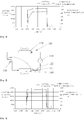
- the compressor is directly started, referring to FIG. 1 , under the suction of the compressor, the evaporator outlet pressure P2 drops rapidly, and the force balance of the three forces disappears.
- the thermal expansion valve Since the pressure P1 is much larger than the spring preload force P3, the thermal expansion valve is quickly opened to a very large opening degree. As the thermal expansion valve opens, the refrigerant compressed by the compressor quickly flows through the evaporator and back to the compressor via the thermal expansion valve. On one hand, this will lead to excessive refrigerant flow and liquid slugging on the compressor; on the other hand, the evaporator outlet pressure P2 is quickly restored at this point, and the opening degree of the thermal expansion valve is greatly reduced in cooperation with the spring preload force P3, resulting in a rapid decrease in the cooling capacity. As a result, the aforementioned problems of the opening degree of thermal expansion valve and corresponding sudden increase and sudden drop of the cooling capacity are caused, which will further affect the system cyclic degradation coefficient and system performance.
- the thermal expansion valve can only be passively adjusted based on system operating conditions. This leads to reaction lag of such systems in responding to the need to adjust the operating conditions, and the lack of adjustment ability to actively respond.
- the present invention provides an air conditioning system, which includes: a compressor, a condenser, a thermal expansion valve and an evaporator connected via a pipeline; and a thermal temperature sensing bulb disposed on an outlet pipeline of the evaporator and associated with the thermal expansion valve; the air conditioning system further including a thermal power source which is thermally coupled to the thermal temperature sensing bulb and controlledly cools or heats the thermal temperature sensing bulb.
- the thermal power source controlledly cools the thermal temperature sensing bulb before the compressor is started.
- the thermal power source controlledly cools or heats the thermal temperature sensing bulb to adjust the degree of superheat of the evaporator outlet.
- the thermal power source is thermally coupled to the thermal temperature sensing bulb by means of thermal radiation, thermal convection or thermal conduction.
- the thermal power source includes a thermoelectric sheet disposed on the thermal temperature sensing bulb.
- the thermal power source includes an energy storage device disposed on the thermal temperature sensing bulb, and the energy storage device draws and stores heat from the evaporator or the condenser during operation of the air conditioning system.
- the air conditioning system is a refrigeration system or a heat pump system.
- a startup control method of an air conditioning system includes: a compressor, a condenser, a thermal expansion valve and an evaporator connected via a pipeline; and a thermal temperature sensing bulb disposed on an outlet pipeline of the evaporator and associated with the thermal expansion valve; and the air conditioning system further includes a thermal power source which is thermally coupled to the thermal temperature sensing bulb; wherein the startup control method includes: the thermal power source controlledly pre-cooling the thermal temperature sensing bulb before the compressor is started, so that a range of valve opening degree oscillation of the thermal expansion valve caused by a temperature change of the thermal temperature sensing bulb is reduced.
- the thermal power source pre-cools the thermal temperature sensing bulb for a target time of 1-60 seconds.
- the thermal power source pre-cools the thermal temperature sensing bulb for a target time of 10-25 seconds.
- the thermal power source pre-cools the thermal temperature sensing bulb to a target temperature in a range of +/-10°C from a final stable temperature of the thermal temperature sensing bulb.
- the thermal power source pre-cools the thermal temperature sensing bulb to a target temperature which corresponds to a final stable temperature of the thermal temperature sensing bulb.
- the thermal power source pre-cools the thermal temperature sensing bulb by means of thermal radiation, thermal convection, or thermal conduction.
- the thermal power source includes a thermoelectric sheet disposed on the thermal temperature sensing bulb.
- the thermal power source includes an energy storage device disposed on the thermal temperature sensing bulb, and the energy storage device draws and stores cooling capacity from the evaporator during operation of the air conditioning system.
- the air conditioning system is a refrigeration system or a heat pump system.
- a control method of an air conditioning system is further provided, wherein the air conditioning system includes: a compressor, a condenser, a thermal expansion valve and an evaporator connected via a pipeline; and a thermal temperature sensing bulb disposed on an outlet pipeline of the evaporator and associated with the thermal expansion valve; and the air conditioning system further includes a thermal power source which is thermally coupled to the thermal temperature sensing bulb; the control method including: the thermal power source controlledly cooling or heating the thermal temperature sensing bulb to adjust the degree of superheat of the evaporator outlet, during steady state operation of the air conditioning system.
- the thermal temperature sensing bulb is cooled or heated, as needed, by a thermal power source thermally coupled to the thermal temperature sensing bulb, thereby enabling the thermal expansion valve associated with the thermal temperature sensing bulb to be opened and closed more smoothly, greatly reducing the opening degree oscillation caused by sudden pressure change, or providing a certain degree of adjustment in the steady state operation of the system, and effectively improving the performance of the air conditioning system.
- the refrigeration system 100 includes a compressor 110, a condenser 120, a thermal expansion valve 130, and an evaporator 140 that are connected via a pipeline.
- the refrigeration system 100 also includes a thermal temperature sensing bulb 131 which is disposed on an outlet pipeline of the evaporator 140 and associated with the thermal expansion valve 130. More critically, the refrigeration system 100 further includes a thermoelectric sheet 132 disposed on the thermal temperature sensing bulb 131, and the thermoelectric sheet 132 controlledly cools or heats the thermal temperature sensing bulb 131.
- FIG. 3 for performance change during system startup, wherein the system is started at the time of 1800s, the oscillation is eliminated by the compressor power consumption within about 40s after the startup, and the steady-state operation is realized at about 1100W; as compared to the oscillation elimination time of about 150s in FIG. 1 , the embodiment in FIG. 3 can achieve a steady-state operation extremely quickly without the need for excess power consumption of the compressor.
- the oscillation of the cooling capacity corresponding to the starting state of the compressor is correspondingly reduced, and the oscillation is eliminated within 40s to achieve a steady-state output of the cooling capacity of about 18000Btu/hr; as compared to the oscillation elimination time of about 150s in FIG. 1 , the embodiment in FIG. 3 can achieve a steady-state output extremely quickly, thus effectively improving the cyclic degradation coefficient and system performance.
- the present concept is described with a set of refrigeration systems as an embodiment, it should be understood that the present concept aims to improve the phenomenon that the oscillation of cooling capacity of a system in which the thermal expansion valve is used as a throttling element is too large, thereby improving the cyclic degradation coefficient and system performance.
- the concept is equally applicable to a heat pump system, or even various types of more general air conditioning systems, which should therefore be included within the scope of the present concept.
- the technical effects of pre-cooling the thermal temperature sensing bulb are described in an application scenario of the refrigeration system after the compressor is shut down and before it is restarted, it should be understood that the concept is applicable to any scenario in which the thermal expansion valve needs to be controlled suddenly.
- the pre-cooling element is intended to make the opening and closing of the thermal expansion valve associated with the thermal temperature sensing bulb smoother, greatly alleviating the oscillation of opening degree caused by sudden pressure change, and thereby improving the performance of the air conditioning system.
- a certain degree of active adjustment function of the thermal expansion valve can also be achieved by the heating or cooling effect of the heating source on the thermal temperature sensing bulb, thereby improving system performance or improving system reliability.
- the thermal power source can controlledly cool the thermal temperature sensing bulb to increase the degree of superheat of the evaporator outlet, thereby preventing liquid-phase refrigerant from entering the compressor and causing liquid slugging damage, and improving compressor reliability.
- thermoelectric sheet is described as an element for cooling or heating the thermal temperature sensing bulb.
- a corresponding purpose can be achieved by disposing a thermal power source at the thermal temperature sensing bulb.
- an energy storage device can be disposed on the thermal temperature sensing bulb, wherein the energy storage device draws and stores a cooling capacity from the evaporator during operation of the air conditioning system, or draws and stores heat from the condenser, and when it is required to cool or heat the thermal expansion valve, the energy storage device releases the heat.
- thermal power sources which are not exhaustively listed herein, but they should all be included within the present concept.
- the thermal power source can be thermally coupled to the thermal temperature sensing bulb by means of thermal radiation, thermal convection or thermal conduction to achieve the purpose of heat transferring.
- a startup control method of an air conditioning system is also provided herein according to the present concept, wherein the air conditioning system includes: a compressor, a condenser, a thermal expansion valve and an evaporator connected via a pipeline; and a thermal temperature sensing bulb disposed on an outlet pipeline of the evaporator and associated with the thermal expansion valve; and the air conditioning system further includes a thermal power source which is thermally coupled to the thermal temperature sensing bulb; wherein the startup control method includes: the thermal power source controlledly pre-cooling the thermal temperature sensing bulb before the compressor is started, so that a range of valve opening degree oscillation of the thermal expansion valve caused by a temperature change of the thermal temperature sensing bulb is reduced.
- the thermal temperature sensing bulb is pre-cooled by the thermal power source thermally coupled to the thermal temperature sensing bulb before the compressor is started, thereby enabling the thermal expansion valve associated with the thermal temperature sensing bulb to be opened and closed more smoothly, greatly reducing the opening degree oscillation caused by sudden pressure change and improving the performance of the air conditioning system.
- the method is also applicable to air conditioning systems in any of the foregoing embodiments or combinations thereof, including but not limited to refrigeration systems or heat pump systems.
- the structural form and arrangement of the thermal power source can be modified accordingly.
- the thermal power source pre-cools the thermal temperature sensing bulb by means of thermal radiation, thermal convection or thermal conduction.
- the thermal power source may include a thermoelectric sheet disposed on the thermal temperature sensing bulb; or it may include an energy storage device disposed on the thermal temperature sensing bulb, and the energy storage device draws and stores a cooling capacity from the evaporator during operation of the air conditioning system. The description will not be expanded herein.
- control target may be set by a pre-cooling duration, for example, 1-60 seconds; for another example, 10-25 seconds; or it may be set according to a pre-cooled temperature, for example, the final stable temperature of the thermal temperature sensing bulb is +/-10°C, and the like. Therefore, a set of closed-loop control is formed, which works only when needed and is closed after the purpose is achieved.
- a control method of an air conditioning system is further provided herein according to the present concept, wherein the air conditioning system includes: a compressor, a condenser, a thermal expansion valve and an evaporator connected via a pipeline; and a thermal temperature sensing bulb disposed on an outlet pipeline of the evaporator and associated with the thermal expansion valve; and the air conditioning system further includes a thermal power source which is thermally coupled to the thermal temperature sensing bulb.
- the control method includes: the thermal power source controlledly cooling or heating the thermal temperature sensing bulb to adjust the degree of superheat of the evaporator outlet, during steady state operation of the air conditioning system.
- This control method can impart a certain degree of active adjustment to the air conditioning system to which the thermal expansion valve is applied, thereby improving system performance or improving system reliability.
- the thermal power source can controlledly cool the thermal temperature sensing bulb to increase the degree of superheat of the evaporator outlet, thereby preventing liquid-phase refrigerant from entering the compressor and causing liquid slugging damage, and improving compressor reliability.
Landscapes
- Engineering & Computer Science (AREA)
- Mechanical Engineering (AREA)
- General Engineering & Computer Science (AREA)
- Physics & Mathematics (AREA)
- Thermal Sciences (AREA)
- Chemical & Material Sciences (AREA)
- Combustion & Propulsion (AREA)
- Air Conditioning Control Device (AREA)
Abstract
Description
- The present invention relates to an air conditioning system and a control method of an air conditioning system, and in particular to a startup control of an air conditioning system.
- For refrigeration systems that do not have a variable frequency device, they typically control the cooling load in the form of frequent switching between on and off modes. For such systems, a cyclic degradation coefficient is often used as one of the indicators for evaluating system performance. That is, it is a parameter indicating a comparison between the dynamic performance (such as cooling capacity and power consumption) provided by the refrigeration system and the steady-state performance of the same system during the cycle of starting and stopping a compressor. When the coefficient is smaller, it indicates that the performance of the corresponding system is better, and when it is larger, the performance is not as good.
- In practical applications, a non-variable frequency refrigeration system in which a thermal expansion valve is used as a throttling element may have a cyclic degradation coefficient of 0.2 or higher. One of the reasons is that an opening degree of the thermal expansion valve will suddenly rise and fall during the re-starting phase after the compressor is stopped, which will be reflected as a violent oscillation of the cooling capacity, that is, an excessive power consumption of the compressor will be caused.
- Specifically, as a mature component in the field of refrigeration, the opening degree of the thermal expansion valve is determined by a resultant force of three forces. In an equilibrium state, the resultant force of a spring preload force P3 in the thermal expansion valve and an evaporator outlet pressure P2 is canceled out with a pressure P1 caused by temperature change of a thermal temperature sensing bulb. After the compressor has been shut down for a period of time, the thermal expansion valve remains closed due to the force balance. At this point, if the compressor is directly started, referring to
FIG. 1 , under the suction of the compressor, the evaporator outlet pressure P2 drops rapidly, and the force balance of the three forces disappears. Since the pressure P1 is much larger than the spring preload force P3, the thermal expansion valve is quickly opened to a very large opening degree. As the thermal expansion valve opens, the refrigerant compressed by the compressor quickly flows through the evaporator and back to the compressor via the thermal expansion valve. On one hand, this will lead to excessive refrigerant flow and liquid slugging on the compressor; on the other hand, the evaporator outlet pressure P2 is quickly restored at this point, and the opening degree of the thermal expansion valve is greatly reduced in cooperation with the spring preload force P3, resulting in a rapid decrease in the cooling capacity. As a result, the aforementioned problems of the opening degree of thermal expansion valve and corresponding sudden increase and sudden drop of the cooling capacity are caused, which will further affect the system cyclic degradation coefficient and system performance. - In addition, when the air conditioning system is in steady-state operation, generally, the thermal expansion valve can only be passively adjusted based on system operating conditions. This leads to reaction lag of such systems in responding to the need to adjust the operating conditions, and the lack of adjustment ability to actively respond.
- Viewed from a first aspect, the present invention provides an air conditioning system, which includes: a compressor, a condenser, a thermal expansion valve and an evaporator connected via a pipeline; and a thermal temperature sensing bulb disposed on an outlet pipeline of the evaporator and associated with the thermal expansion valve; the air conditioning system further including a thermal power source which is thermally coupled to the thermal temperature sensing bulb and controlledly cools or heats the thermal temperature sensing bulb.
- Optionally, the thermal power source controlledly cools the thermal temperature sensing bulb before the compressor is started.
- Optionally, during steady state operation of the air conditioning system, the thermal power source controlledly cools or heats the thermal temperature sensing bulb to adjust the degree of superheat of the evaporator outlet.
- Optionally, the thermal power source is thermally coupled to the thermal temperature sensing bulb by means of thermal radiation, thermal convection or thermal conduction.
- Optionally, the thermal power source includes a thermoelectric sheet disposed on the thermal temperature sensing bulb.
- Optionally, the thermal power source includes an energy storage device disposed on the thermal temperature sensing bulb, and the energy storage device draws and stores heat from the evaporator or the condenser during operation of the air conditioning system.
- Optionally, the air conditioning system is a refrigeration system or a heat pump system.
- According to another aspect of the invention, a startup control method of an air conditioning system is also provided, wherein the air conditioning system includes: a compressor, a condenser, a thermal expansion valve and an evaporator connected via a pipeline; and a thermal temperature sensing bulb disposed on an outlet pipeline of the evaporator and associated with the thermal expansion valve; and the air conditioning system further includes a thermal power source which is thermally coupled to the thermal temperature sensing bulb; wherein the startup control method includes: the thermal power source controlledly pre-cooling the thermal temperature sensing bulb before the compressor is started, so that a range of valve opening degree oscillation of the thermal expansion valve caused by a temperature change of the thermal temperature sensing bulb is reduced.
- Optionally, the thermal power source pre-cools the thermal temperature sensing bulb for a target time of 1-60 seconds.
- Optionally, the thermal power source pre-cools the thermal temperature sensing bulb for a target time of 10-25 seconds.
- Optionally, the thermal power source pre-cools the thermal temperature sensing bulb to a target temperature in a range of +/-10°C from a final stable temperature of the thermal temperature sensing bulb.
- Optionally, the thermal power source pre-cools the thermal temperature sensing bulb to a target temperature which corresponds to a final stable temperature of the thermal temperature sensing bulb.
- Optionally, the thermal power source pre-cools the thermal temperature sensing bulb by means of thermal radiation, thermal convection, or thermal conduction.
- Optionally, the thermal power source includes a thermoelectric sheet disposed on the thermal temperature sensing bulb.
- Optionally, the thermal power source includes an energy storage device disposed on the thermal temperature sensing bulb, and the energy storage device draws and stores cooling capacity from the evaporator during operation of the air conditioning system.
- Optionally, the air conditioning system is a refrigeration system or a heat pump system.
- According to still another aspect of the invention, a control method of an air conditioning system is further provided, wherein the air conditioning system includes: a compressor, a condenser, a thermal expansion valve and an evaporator connected via a pipeline; and a thermal temperature sensing bulb disposed on an outlet pipeline of the evaporator and associated with the thermal expansion valve; and the air conditioning system further includes a thermal power source which is thermally coupled to the thermal temperature sensing bulb; the control method including: the thermal power source controlledly cooling or heating the thermal temperature sensing bulb to adjust the degree of superheat of the evaporator outlet, during steady state operation of the air conditioning system.
- In accordance with the above, the thermal temperature sensing bulb is cooled or heated, as needed, by a thermal power source thermally coupled to the thermal temperature sensing bulb, thereby enabling the thermal expansion valve associated with the thermal temperature sensing bulb to be opened and closed more smoothly, greatly reducing the opening degree oscillation caused by sudden pressure change, or providing a certain degree of adjustment in the steady state operation of the system, and effectively improving the performance of the air conditioning system.
- The technical solutions of the present invention will be further described in detail below with reference to the accompanying drawings and embodiments, but it should be understood that the drawings are only provided for the purpose of explanation, and should not be considered as limiting the scope of the present invention, as defined by the claims. In addition, unless otherwise specified, the drawings are only intended to conceptually illustrate the structures and constructions described herein, and are not necessarily drawn to scale.
-
FIG. 1 is a schematic diagram showing oscillation of a cooling capacity of a refrigeration system in the prior art when it is restarted; -
FIG. 2 is a schematic diagram of an embodiment of a proposed refrigeration system; and -
FIG. 3 is a schematic diagram showing oscillation of a cooling capacity of the proposed refrigeration system when it is restarted. - Although the features of the present invention are disclosed in connection with one or more of the embodiments, such features can be combined with one or more other features of other implementations/embodiments, as may be desired and/or advantageous for any given or identifiable function.
- Referring to
FIG. 2 , a refrigeration system is provided herein. Therefrigeration system 100 includes acompressor 110, acondenser 120, athermal expansion valve 130, and anevaporator 140 that are connected via a pipeline. Therefrigeration system 100 also includes a thermaltemperature sensing bulb 131 which is disposed on an outlet pipeline of theevaporator 140 and associated with thethermal expansion valve 130. More critically, therefrigeration system 100 further includes athermoelectric sheet 132 disposed on the thermaltemperature sensing bulb 131, and thethermoelectric sheet 132 controlledly cools or heats the thermaltemperature sensing bulb 131. - Under this arrangement, before the compressor is started, due to the pre-cooling action of the
thermoelectric sheet 132 on the thermaltemperature sensing bulb 131, a pressure P1 associated with the temperature change of the thermal temperature sensing bulb is relatively decreased by a certain amount as the temperature is lowered. At this point, if the compressor is restarted, a resultant force of the pressure P1 and a spring preload force P3 is correspondingly reduced, and the amplification of the opening degree of the thermal expansion valve is correspondingly small, whereby the oscillation of opening degree subsequently caused by rebalanced pressure is also reduced. - Specifically, reference may be made to
FIG. 3 for performance change during system startup, wherein the system is started at the time of 1800s, the oscillation is eliminated by the compressor power consumption within about 40s after the startup, and the steady-state operation is realized at about 1100W; as compared to the oscillation elimination time of about 150s inFIG. 1 , the embodiment inFIG. 3 can achieve a steady-state operation extremely quickly without the need for excess power consumption of the compressor. With continued reference toFIG. 3 , the oscillation of the cooling capacity corresponding to the starting state of the compressor is correspondingly reduced, and the oscillation is eliminated within 40s to achieve a steady-state output of the cooling capacity of about 18000Btu/hr; as compared to the oscillation elimination time of about 150s inFIG. 1 , the embodiment inFIG. 3 can achieve a steady-state output extremely quickly, thus effectively improving the cyclic degradation coefficient and system performance. - Although the present concept is described with a set of refrigeration systems as an embodiment, it should be understood that the present concept aims to improve the phenomenon that the oscillation of cooling capacity of a system in which the thermal expansion valve is used as a throttling element is too large, thereby improving the cyclic degradation coefficient and system performance. Thus, it will be apparent to those skilled in the art, in the light the teachings of the present concept, that the concept is equally applicable to a heat pump system, or even various types of more general air conditioning systems, which should therefore be included within the scope of the present concept.
- Similarly, although in the foregoing embodiment, the technical effects of pre-cooling the thermal temperature sensing bulb are described in an application scenario of the refrigeration system after the compressor is shut down and before it is restarted, it should be understood that the concept is applicable to any scenario in which the thermal expansion valve needs to be controlled suddenly. The pre-cooling element is intended to make the opening and closing of the thermal expansion valve associated with the thermal temperature sensing bulb smoother, greatly alleviating the oscillation of opening degree caused by sudden pressure change, and thereby improving the performance of the air conditioning system. In addition, a certain degree of active adjustment function of the thermal expansion valve can also be achieved by the heating or cooling effect of the heating source on the thermal temperature sensing bulb, thereby improving system performance or improving system reliability. For example, during a steady state operation of the air conditioning system, the thermal power source can controlledly heat the thermal temperature sensing bulb to reduce the degree of superheat of the evaporator outlet, thereby improving the cooling efficiency of the system from a thermodynamic point of view (e.g., COP=cooling capacity/power consumption). For another example, during the steady state operation of the air conditioning system, the thermal power source can controlledly cool the thermal temperature sensing bulb to increase the degree of superheat of the evaporator outlet, thereby preventing liquid-phase refrigerant from entering the compressor and causing liquid slugging damage, and improving compressor reliability.
- Further, in the foregoing embodiments, the thermoelectric sheet is described as an element for cooling or heating the thermal temperature sensing bulb. In fact, it is not intended to limit the present concept. In the light of the teachings of present concept, a corresponding purpose can be achieved by disposing a thermal power source at the thermal temperature sensing bulb. For example, an energy storage device can be disposed on the thermal temperature sensing bulb, wherein the energy storage device draws and stores a cooling capacity from the evaporator during operation of the air conditioning system, or draws and stores heat from the condenser, and when it is required to cool or heat the thermal expansion valve, the energy storage device releases the heat. It is of course also possible to use other thermal power sources, which are not exhaustively listed herein, but they should all be included within the present concept. Similarly, for the arrangement between the thermal source and the thermal expansion valve, a contact arrangement not necessarily required. According to the conduction mode of heat, the thermal power source can be thermally coupled to the thermal temperature sensing bulb by means of thermal radiation, thermal convection or thermal conduction to achieve the purpose of heat transferring.
- Accordingly, a startup control method of an air conditioning system is also provided herein according to the present concept, wherein the air conditioning system includes: a compressor, a condenser, a thermal expansion valve and an evaporator connected via a pipeline; and a thermal temperature sensing bulb disposed on an outlet pipeline of the evaporator and associated with the thermal expansion valve; and the air conditioning system further includes a thermal power source which is thermally coupled to the thermal temperature sensing bulb; wherein the startup control method includes: the thermal power source controlledly pre-cooling the thermal temperature sensing bulb before the compressor is started, so that a range of valve opening degree oscillation of the thermal expansion valve caused by a temperature change of the thermal temperature sensing bulb is reduced. According to the method, the thermal temperature sensing bulb is pre-cooled by the thermal power source thermally coupled to the thermal temperature sensing bulb before the compressor is started, thereby enabling the thermal expansion valve associated with the thermal temperature sensing bulb to be opened and closed more smoothly, greatly reducing the opening degree oscillation caused by sudden pressure change and improving the performance of the air conditioning system.
- Similarly, the method is also applicable to air conditioning systems in any of the foregoing embodiments or combinations thereof, including but not limited to refrigeration systems or heat pump systems. Of course, when the method is applied to the air conditioning system in the foregoing embodiment, the structural form and arrangement of the thermal power source can be modified accordingly. For example, the thermal power source pre-cools the thermal temperature sensing bulb by means of thermal radiation, thermal convection or thermal conduction. For another example, the thermal power source may include a thermoelectric sheet disposed on the thermal temperature sensing bulb; or it may include an energy storage device disposed on the thermal temperature sensing bulb, and the energy storage device draws and stores a cooling capacity from the evaporator during operation of the air conditioning system. The description will not be expanded herein.
- It should be understood that there should be a control target of pre-cooling when implementing the method of the foregoing embodiment. The control target may be set by a pre-cooling duration, for example, 1-60 seconds; for another example, 10-25 seconds; or it may be set according to a pre-cooled temperature, for example, the final stable temperature of the thermal temperature sensing bulb is +/-10°C, and the like. Therefore, a set of closed-loop control is formed, which works only when needed and is closed after the purpose is achieved.
- Accordingly, a control method of an air conditioning system is further provided herein according to the present concept, wherein the air conditioning system includes: a compressor, a condenser, a thermal expansion valve and an evaporator connected via a pipeline; and a thermal temperature sensing bulb disposed on an outlet pipeline of the evaporator and associated with the thermal expansion valve; and the air conditioning system further includes a thermal power source which is thermally coupled to the thermal temperature sensing bulb. The control method includes: the thermal power source controlledly cooling or heating the thermal temperature sensing bulb to adjust the degree of superheat of the evaporator outlet, during steady state operation of the air conditioning system. This control method can impart a certain degree of active adjustment to the air conditioning system to which the thermal expansion valve is applied, thereby improving system performance or improving system reliability. For example, during steady state operation of the air conditioning system, the thermal power source can controlledly heat the thermal temperature sensing bulb to reduce the degree of superheat of the evaporator outlet, thereby improving the cooling efficiency of the system from a thermodynamic point of view (e.g., COP=cooling capacity/power consumption). For another example, during the steady state operation of the air conditioning system, the thermal power source can controlledly cool the thermal temperature sensing bulb to increase the degree of superheat of the evaporator outlet, thereby preventing liquid-phase refrigerant from entering the compressor and causing liquid slugging damage, and improving compressor reliability.
- While specific order of steps may have been shown, disclosed, and claimed in particular embodiments of the present disclosure, it is understood that the steps can be carried out, separated or combined in any order unless otherwise indicated, which will still benefit from the disclosure.
- In the description, examples are used to disclose the present invention, including the best mode, with the purpose of enabling any person skilled in the art to practice the application, including making and using any device or system and performing any of the methods covered. The scope of protection of the present invention is defined by the claims, and may include other examples that can be conceived by those skilled in the art. If such other examples have structural elements that do not differ from the literal language of the claims, or if they include equivalent structural elements that do not substantively differ from the literal language of the claims, these examples are also intended to be included in the scope of the claims.
Claims (10)
- An air conditioning system, comprising: a compressor, a condenser, a thermal expansion valve and an evaporator connected via a pipeline; and a thermal temperature sensing bulb disposed on an outlet pipeline of the evaporator and associated with the thermal expansion valve; the air conditioning system further comprising a thermal power source which is thermally coupled to the thermal temperature sensing bulb and controlledly cools or heats the thermal temperature sensing bulb.
- The air conditioning system according to claim 1, wherein the thermal power source controlledly cools the thermal temperature sensing bulb before the compressor is started.
- The air conditioning system according to claim 1 or 2, wherein during steady state operation of the air conditioning system, the thermal power source controlledly cools or heats the thermal temperature sensing bulb to adjust the degree of superheat of the evaporator outlet.
- The air conditioning system according to claim 1, 2 or 3, wherein the thermal power source comprises a thermoelectric sheet disposed on the thermal temperature sensing bulb, or an energy storage device disposed on the thermal temperature sensing bulb, and the energy storage device draws and stores heat from the evaporator or the condenser during operation of the air conditioning system.
- A control method of an air conditioning system, the air conditioning system comprising: a compressor, a condenser, a thermal expansion valve and an evaporator connected via a pipeline; and a thermal temperature sensing bulb disposed on an outlet pipeline of the evaporator and associated with the thermal expansion valve; and the air conditioning system further comprising a thermal power source which is thermally coupled to the thermal temperature sensing bulb;
the control method comprising: the thermal power source controlledly pre-cooling the thermal temperature sensing bulb before the compressor is started, so that a range of valve opening degree oscillation of the thermal expansion valve caused by a temperature change of the thermal temperature sensing bulb is reduced. - The startup control method according to claim 5, wherein the thermal power source pre-cools the thermal temperature sensing bulb for a target time of 1-60 seconds.
- The startup control method according to claim 6, wherein the thermal power source pre-cools the thermal temperature sensing bulb for a target time of 10-25 seconds.
- The startup control method according to claim 5, 6 or 7, wherein the thermal power source pre-cools the thermal temperature sensing bulb to a target temperature in a range of +/-10°C from a final stable temperature of the thermal temperature sensing bulb.
- The startup control method according to any of claims 5 to 8, wherein the thermal power source pre-cools the thermal temperature sensing bulb to a target temperature which corresponds to a final stable temperature of the thermal temperature sensing bulb.
- A control method of an air conditioning system, the air conditioning system comprising: a compressor, a condenser, a thermal expansion valve and an evaporator connected via a pipeline; and a thermal temperature sensing bulb disposed on an outlet pipeline of the evaporator and associated with the thermal expansion valve; and the air conditioning system further comprising a thermal power source which is thermally coupled to the thermal temperature sensing bulb;
the control method comprising: the thermal power source controlledly cooling or heating the thermal temperature sensing bulb to adjust the degree of superheat of the evaporator outlet, during steady state operation of the air conditioning system.
Applications Claiming Priority (1)
| Application Number | Priority Date | Filing Date | Title |
|---|---|---|---|
| CN201910261297.XA CN111765614A (en) | 2019-04-02 | 2019-04-02 | Air conditioning system and control method thereof |
Publications (1)
| Publication Number | Publication Date |
|---|---|
| EP3719420A1 true EP3719420A1 (en) | 2020-10-07 |
Family
ID=70049864
Family Applications (1)
| Application Number | Title | Priority Date | Filing Date |
|---|---|---|---|
| EP20165873.9A Ceased EP3719420A1 (en) | 2019-04-02 | 2020-03-26 | Air conditioning system and control method thereof |
Country Status (3)
| Country | Link |
|---|---|
| US (1) | US20200318881A1 (en) |
| EP (1) | EP3719420A1 (en) |
| CN (1) | CN111765614A (en) |
Families Citing this family (2)
| Publication number | Priority date | Publication date | Assignee | Title |
|---|---|---|---|---|
| CN112944706A (en) * | 2021-02-20 | 2021-06-11 | 冷王(上海)实业有限公司 | Transport refrigeration unit and control method thereof |
| CN113983726A (en) * | 2021-11-29 | 2022-01-28 | 张琛 | Variable-flow thermostatic expansion valve air conditioning system |
Citations (5)
| Publication number | Priority date | Publication date | Assignee | Title |
|---|---|---|---|---|
| JPS5494150A (en) * | 1978-01-06 | 1979-07-25 | Hitachi Ltd | Freezer |
| WO1990004224A1 (en) * | 1988-10-05 | 1990-04-19 | Joseph Marsala | Apparatus for controlling a thermostatic expansion valve |
| EP0450703A1 (en) * | 1990-03-29 | 1991-10-09 | Cooltronic B.V. | Cooling machine and an optimalized thermostatic expansion valve therefor |
| DE19647718C2 (en) * | 1996-11-19 | 1998-09-24 | Danfoss As | Process for regulating a refrigeration system as well as refrigeration system and expansion valve |
| US5966950A (en) * | 1997-11-17 | 1999-10-19 | Danfoss A/S | Method of regulating a refrigeration circuit |
Family Cites Families (2)
| Publication number | Priority date | Publication date | Assignee | Title |
|---|---|---|---|---|
| CN106016602B (en) * | 2016-05-25 | 2019-09-17 | 青岛海尔空调电子有限公司 | A kind of embedded type air conditioner control method |
| CN108088041B (en) * | 2017-12-06 | 2021-06-22 | 广东美的制冷设备有限公司 | Control method of electronic expansion valve, radiation air conditioner and storage medium |
-
2019
- 2019-04-02 CN CN201910261297.XA patent/CN111765614A/en active Pending
-
2020
- 2020-03-26 EP EP20165873.9A patent/EP3719420A1/en not_active Ceased
- 2020-04-01 US US16/837,593 patent/US20200318881A1/en not_active Abandoned
Patent Citations (6)
| Publication number | Priority date | Publication date | Assignee | Title |
|---|---|---|---|---|
| JPS5494150A (en) * | 1978-01-06 | 1979-07-25 | Hitachi Ltd | Freezer |
| WO1990004224A1 (en) * | 1988-10-05 | 1990-04-19 | Joseph Marsala | Apparatus for controlling a thermostatic expansion valve |
| EP0450703A1 (en) * | 1990-03-29 | 1991-10-09 | Cooltronic B.V. | Cooling machine and an optimalized thermostatic expansion valve therefor |
| EP0450703B1 (en) * | 1990-03-29 | 1994-10-12 | Cooltronic B.V. | Cooling machine and an optimalized thermostatic expansion valve therefor |
| DE19647718C2 (en) * | 1996-11-19 | 1998-09-24 | Danfoss As | Process for regulating a refrigeration system as well as refrigeration system and expansion valve |
| US5966950A (en) * | 1997-11-17 | 1999-10-19 | Danfoss A/S | Method of regulating a refrigeration circuit |
Also Published As
| Publication number | Publication date |
|---|---|
| US20200318881A1 (en) | 2020-10-08 |
| CN111765614A (en) | 2020-10-13 |
Similar Documents
| Publication | Publication Date | Title |
|---|---|---|
| US20150059367A1 (en) | Active charge control methods for vapor cycle refrigeration or heat pump systems | |
| US20130180272A1 (en) | Expansion-valve control device, heat-source unit, and expansion-valve control method | |
| JP5581300B2 (en) | Thermal control method and system | |
| JP7454918B2 (en) | Fluid preparation method and test chamber | |
| CN105371545A (en) | An air conditioner and a refrigerant circulation quantity adjusting method for a refrigeration system thereof | |
| JP5984456B2 (en) | Heat source system control device, heat source system control method, heat source system, power adjustment network system, and heat source machine control device | |
| US20140196489A1 (en) | Energy-optimized cycle control of time-variant loads for thermal management of vapor compression systems | |
| WO2012032699A1 (en) | Refrigeration cycle device | |
| US20200318881A1 (en) | Air conditioning system and control method thereof | |
| US9341401B2 (en) | Heat source system and control method therefor | |
| CN110234944B (en) | Cooling System | |
| CN114811892B (en) | Variable frequency air conditioner and control method and control device thereof | |
| KR20230066017A (en) | Temperature control device using multi-stage refrigeration cycle and temperature control method using the same | |
| WO2019111771A1 (en) | Expansion valve control sensor, and refrigeration system employing same | |
| JP5119513B2 (en) | Dual refrigerator | |
| WO2021223530A1 (en) | Control method for inverter air conditioner | |
| JP7448443B2 (en) | Cooling device and cooling device control method | |
| JPH09133435A (en) | Expansion valve | |
| JP2009168258A (en) | Dual refrigerator | |
| WO2018108117A1 (en) | Refrigerator for improving stability of linear compressor, and control method therefor | |
| JP5412073B2 (en) | Heat source system and control method thereof | |
| CN219797562U (en) | Refrigerating system and refrigerator | |
| JP4859203B2 (en) | Refrigeration apparatus and operation control method thereof | |
| WO2012043229A1 (en) | Control device for cooling installation device | |
| JP2024178902A (en) | Cooling system |
Legal Events
| Date | Code | Title | Description |
|---|---|---|---|
| PUAI | Public reference made under article 153(3) epc to a published international application that has entered the european phase |
Free format text: ORIGINAL CODE: 0009012 |
|
| STAA | Information on the status of an ep patent application or granted ep patent |
Free format text: STATUS: THE APPLICATION HAS BEEN PUBLISHED |
|
| AK | Designated contracting states |
Kind code of ref document: A1 Designated state(s): AL AT BE BG CH CY CZ DE DK EE ES FI FR GB GR HR HU IE IS IT LI LT LU LV MC MK MT NL NO PL PT RO RS SE SI SK SM TR |
|
| AX | Request for extension of the european patent |
Extension state: BA ME |
|
| STAA | Information on the status of an ep patent application or granted ep patent |
Free format text: STATUS: REQUEST FOR EXAMINATION WAS MADE |
|
| 17P | Request for examination filed |
Effective date: 20210407 |
|
| RBV | Designated contracting states (corrected) |
Designated state(s): AL AT BE BG CH CY CZ DE DK EE ES FI FR GB GR HR HU IE IS IT LI LT LU LV MC MK MT NL NO PL PT RO RS SE SI SK SM TR |
|
| STAA | Information on the status of an ep patent application or granted ep patent |
Free format text: STATUS: EXAMINATION IS IN PROGRESS |
|
| 17Q | First examination report despatched |
Effective date: 20230516 |
|
| STAA | Information on the status of an ep patent application or granted ep patent |
Free format text: STATUS: THE APPLICATION HAS BEEN REFUSED |
|
| 18R | Application refused |
Effective date: 20240723 |